

ZILOG Z86227 Datasheet
GENERAL DESCRIPTION
CPS DC-4074-01
Z86227
CUSTOMER PROCUREMENT SPECIFICATION
Z86227
40-PIN LOW-COST DIGITAL
TELEVISION CONTROLLER (4LDTC)
The Z86227 40-pin Low-Cost Digital Television Controller
(4LDTC) introduces a new level of sophistication to single-chip
architecture. The Z86227 is a member of the Z8® single-chip
microcontroller family with 6 Kbytes of ROM and 236 bytes of
RAM. The device is offered in a 40-pin package and is CMOS
compatible. The 4LDTC offers mask programmed ROM which
enables the Z8 microcontroller to be used in a high volume
production application device embedded with a custom program
(customer supplied program) and combines together with the
Z86C27 (DTC) and Z86127 (LDTC) to provide support for high
end, mid range and low end TV applications.
Zilog’s 4LDTC offers fast execution, efficient use of memory,
sophisticated interrupts, input/output bit manipulation capabilities,
and easy hardware/software system expansion along with low
cost and low power consumption. The device provides an ideal
performance and reliability solution for consumer and industrial
television applications.
The Z86227 architecture is characterized by utilizing Zilog’s
advanced Superintegration™ design methodology. The device
has an 8-bit internal data path controlled by a Z8 microcontroller
and On Screen Display (OSD) logic circuits and Pulse Width
Modulators (PWM). On-chip peripherals include two register
mapped I/O ports (Ports 2 and Port 3), interrupt control logic (one
software, two external and three internal interrupts) and a standby
mode recovery input port (Port 3, pin P30).
used for controlling audio signal levels. Three
8-bit PWM ports used to vary picture levels.
The 4LDTC applications demand powerful I/O capabilities. The
Z86227 fulfills this with 24 pins dedicated to input or output.
These lines are grouped into three ports, and are configurable
under software control to provide timing, status signals, parallel
I/O and an address/data bus for interfacing to external memory.
There are three basic address spaces available to support this
wide range of configurations: Program Memory, Video RAM,
and Register File. The Register File is composed of 236 bytes of
general purpose registers, two I/O Port registers, 15 control and
status registers and three reserved registers.
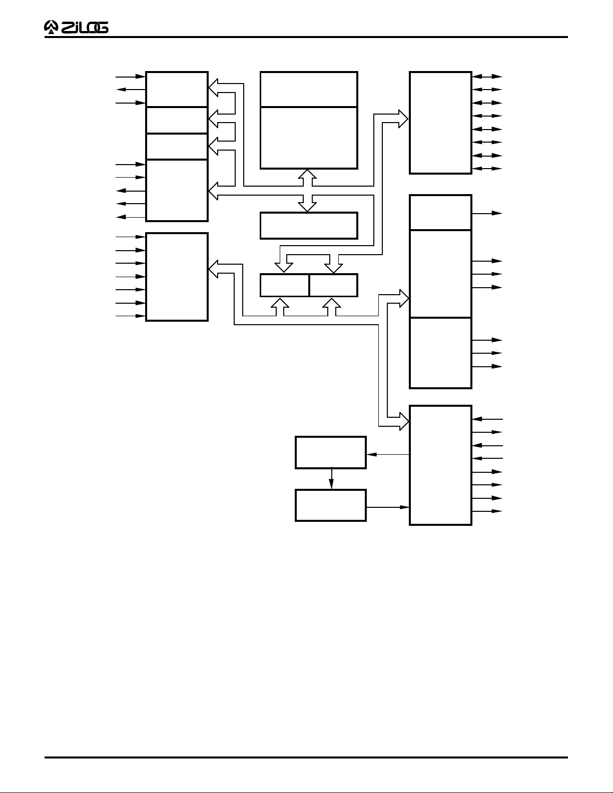
To unburden the program from coping with the real-time problems
such as counting/timing and data communication, the 4LDTC
offers two on-chip counter/timers with a large number of user
selectable modes (Figure 1).
Notes:
All Signals with a preceding front slash, "/", are active Low, e.g.: B//W
(WORD is active Low); /B/W (BYTE is active Low, only).
Power connections follow conventional descriptions below:
Connection Circuit Device
The OSD control circuits support 6 rows by 20 columns of
characters. The character color is specified by row. One of the
eight rows is assigned to show two kinds of colors for bar type
displays such as volume control. The OSD is capable of displaying
either low resolution (5x7 dot pattern) or high resolution (11x15
dot pattern) characters.
A 14-bit PWM port provides enough voltage resolution for a
voltage synthesizer tuning system. Three 6-bit PWM ports are
DC 4074-01 (8-25-93)
Power V
Ground GND V
CC
V
DD
SS
1
GENERAL DESCRIPTION (Continued)
T
CPS DC-4074-01
Z86227
XTAL1
XTAL2
/RESET
P30
P31
P34
P35
P36
P60
P61
P62
P63
P64
P65
AFCIN
RESET
Oscillator
WDT
Counter
Timer
Counter
Timer
Port 3/
Interrupt
Port 6
(Control)
6 KByte
Program ROM
Z8 CPU
Core
256 Byte
Register File
Port 0
Port 1
A8-15 AD0-7
Port 2
PWM 1
14 -bit
PWM 6
to
PWM 8
6-bit
PWM 9
to
PWM11
P27
P26
P25
P24
P23
P22
P21
P20
PWM 1
PWM 6
PWM 7
PWM 8
PWM 9
PWM 10
PWM 11
120 Byte
Character RAM
3 KByte
Character ROM
Functional Block Diagram
On Screen
Display
OSCIN
OSCOU
HSYNC
VSYNC
VRED
VGREEN
VBLUE
VBLANK
2

PIN CONFIGURATION
(
)
CPS DC-4074-01
Z86227
PWM1
P35
P36
P34
P31
P30
XTAL1
XTAL2
/RESET
P60
GND
P61
P62
VCC
P63
P64
P65
AFCIN
OSCIN
OSCOUT
1
2
3
4
5
6
7
8
9
10
11
12
13
14
15
16
17
18
19
20
Z86227
LDTC
40
39
38
37
36
35
34
33
32
31
30
29
28
27
26
25
24
23
22
21
PWM6
PWM7
PWM8
PWM9
PWM10
PWM11
P27
P26
P25
P24
P23
P22
P21
P20
VBLANK
VBLUE
VGREEN
VRED
VSYNC
HSYNC
40-Pin Mask-ROM Plastic DIP
3
 Loading...