

Page 1

IMACS-200 System Reference Guide
October 2007
Document Part Number: 830-01760 -01 Revi si on A2
Release 2.0.0
Page 2

Zhone Technologies
@Zhone Way
7001 Oakport Street
Oakland, CA 94621
USA
510.777.7000
www.zhone.com
info@zhone.com
COPYRIGHT ©2000-2007 Zhone Technologies, Inc. and its licensors. All rights reserved.
This publication is protected by copyright law. No part of this publication may be copied or distributed, transmitted, transcribed,
stored in a retrieval system, or translated into any human or computer language in any form or by any means, electronic,
mechanical, magnetic, manual or otherwise, or disclosed to third parties without the express written permission from Zhone
Technologies, Inc.
AccessNode, BAN, GigaMux, IMACS, MALC, Raptor, SLMS, Z-Edge, Zhone, ZMS, and t he Z hone logo are trademarks of
Zhone Technologies, Inc.
Zhone Technologies makes no representation or warranties with respect to the contents hereof and specifically disclaims any
implied warranties of merchantability, non infringement, or fitness for a particular purpose. Further, Zhone Technologies reserves
the right to revise this publication and to make changes from time to time in the contents hereof without obligation of Zhone
Technologies to notify any person of such revision or changes.
Page 3

Product Description
1Product Description
Release 2.0.2 is the fifth software release for the IMACS-200 platform. The IMACS-200
offers a sub-set of the traditional IMACS interfaces optimized for use in smaller locations. It
also is designed to oper ate ov er an e xtende d t emperature r ange suc h that it c an be i nstal led i n
locations that do not provide a controlled environment. The same "look and feel" of the
IMACS has been maintained for this n ew product offering so that those familiar with the
IMACS product line will quickly be able to configure and successfully deploy the
IMACS-200. Highlights of this new product offering are outlined below.
2 Features Delive red in Pr eviou s Releases
1.0.0
• Data capability: Four LD-SRU ports.
• Voice ports: Four 2-wire E&M transmit only (TO) and four FXS ports.
• Ethernet and RS-232 craft ports
• WAN capability for Four T1 interfaces.
• Two V.35 interfaces.
• Four alarm outputs and four external telemetry inputs.
• Two Optical HSU ports capability is offered as an option conforming to IEEE 37.94
Standard.
• Redundant power supplies of -48VDC, 120VAC or 220VAC are offered as an option.
1.0.1
• Support for E&M Type I and Type II signaling.
• E&M test screen.
• IP Daisy-chaining.
• HSU loop-back capability.
• WAN to WAN trunk signaling to support two IMACS-200’s worth of DS0’s.
1.0.2
• Security enhancement with the introduction of a login log event.
• Fast Circuit Restore
• Allow spaces in the Nod e ID field
• Main screen notification of individual port states.
• Selection of DXS and CSU WAN functions.
Product Description i
Page 4

Features introduced in this Release (2.0.0)
Running Head
• Allow FXS gain to be as high as +6.5 dB.
1.0.3
• E&M signalling support for Type IV and Type V.
• SNMP support for Online (must use version 2.0.0 of Online Software).
• Support for E1 signaling on the WAN facilities
• Introduction of the SA4 management channel bit for E1 customers.
• IPR (IP Routing) capabil ities.
• Remote upgrade from EMS (requires use of 2.0.0 Onlin e Softwar e)
3 Features introduced in this Release (2.0.0)
• Optical WAN daughter card as an option.
• 125 VDC version of the product.
Model No.
4 Notable System Improvements
In addition to the feature content described above, some other system improvements have
been introduced. They include, but are not limited to, the following:
• None.
5 IMACS-200 Initialization and Control
The IMACS-200 initializes and controls the system on power up. It performs the following
functions:
• Initializes the system upon power-up, and runs a self-test on all ports.
• Polls all por ts in the system to determine their operating status.
• Processes all incoming operator commands and displays the responses in a series of
operator interface screens for each port in the system. The operator interface system
(local VT-100 terminal, remote computer, or network management system) connects to
the Serial Interface port, which sends these commands for processing.
• Includes circuitry that allows you to cross-connect DS0 time slots between T1 lines
connected to system WAN ports. Refer to the DS0 time slot assignment operations.
• Includes a test pattern generator for T1 line test purposes.
ii Product Description
Page 5

• Enables Ethernet connec tion for remote management, config uration and downl oading of
host code via a 10baseT Etherne t port. T o setup the Ethernet port, see “Se tting Up Remote
Connectivity” on page 21 of Chapter 4, General Featur es. To download and activa te new
software, see “Loading the Software Image Using the Ethernet Port” on page 40 of
Chapter 4, General Features.
6 System Reference Guide
This System Reference Guide assists technicians in unpacking, assembling, installing,
configuring, and operating the integrated access device.
Chapter 1. System Overview
Chapter 2. System Installation
Chapter 3. System Configuration and Operation
System Reference Guide
Chapter 4. General Features
Chapter 5. WAN Ports
Chapter 6. FXS Ports
Chapter 7. E&M Ports
Chapter 8. Sub Rate Data Ports (SRU)
Chapter 9. High Speed Data Ports (HSU)
Chapter 10. Optical High Speed Data Ports (OHSU)
Chapter 11. Alarms
Chapter 12. IP Routing
Chapter 13. Optical WAN board (OWAN).
Chapter 14. System Testing and Diagnostics
Appendix A. System Specifications
Appendix B. Error Messages
Glossary
Product Description iii
Page 6

Technical support
Running Head
7 Technical support
If you require assistance with the installation or operation of your product, or if you
want to return a product for repair under warranty, contact Zhone customer service.
The contact informatio n is as follows:
E-mail support@zhone.com
Telephone (North America) 877-ZHONE20
Telephone (International) 510-777-7133
Internet www.zhone.com/support
If you purchased the product from an authorized dealer, distributor, Value Added
Reseller (VAR), or third party, contact that supplier for technical assistance and
warranty support.
8 Service Requirements
Model No.
If the product malfunctions, all repairs must be performed by the manufacturer or a
Zhone-authorized agent. It is the responsibility of users requiring service to report the
need for service to Zhone customer service.
9 Safety Information and Precautions
The equipment is designed and manufactured in compliance with the European Safety
Standard EN60950 and the Unites S tate s UL60950 Saf ety S tandard s. However, the following
precautions should be observed to ensure personal safety during installation or service, and
prevent damage to the equipment or equipment to be connected.
Read and follow all warning notices and instructi ons marked on the product or included in this
Reference Guide.
Only qualified technicians should perform these tasks.
1. Never install telephone wiring during a lightning storm.
2. Never install telephone jacks in wet locations unless the jack is specifically designed
for wet locations.
3. Never touch uninsulated telephone wires or terminals unless the telephone line has
been disconnected at the network interface.
4. Use caution when installing or modifying telephone lines.
5. See the UL Statement for Voice ports.
iv Product Description
Page 7

Safety Information and Precautions
6. Never attempt to open the case.
7. The AC versions of this product is intended to be us ed with a three-wire groun ding type
plug - a plug which has a grounding pin . This is a safety feat ure. Equipment gr ounding
is vital to ensure safe opera ti on. Do no t def ea t the purpo se of t h e grou ndi ng typ e plug
by modifying the plug or using an adapter.
Prior to installation, use an outlet tester or a voltmeter to check the AC receptacle for
the presence of earth g round. If the receptacl e is not properly gro unded, the install ation
must not continue until a qualified electric ian has corrected the pro blem. If a three-wire
grounding type power source is not available, consult a qualified electrician to
determine another method of grounding the equipment.
The DC versions of this product must be connected properly with the -VDC and return
(RTN) leads. The grounding screw provided on the right rear of the chassis should be
connected to frame ground.
8. Slots and openings in the cabinet are provided for ventilation. To ensure reliable
operation of the product and to protect it from overheating, these slots and openings
must not be blocked or covered.
9. DO NOT allow a nything to r est on the power cord and do not locat e the produc t where
persons could step on or walk on the power cord.
10. DO NOT attempt to service this product yourself. Refer all servicing to qualified
service personnel.
11. Special cable s, which may b e required by the regulatory inspect ion authority for the
installation site, are the responsibility of the customer.
12. When installed in the final c onfiguration, the product must comp ly with the appli cable
Safety Standards and regulatory requirements of the country in which it is installed.
If necessary, consult with the appropriate regulatory agencies and inspection
authoritie s to ensure compliance.
13. A rare phenomenon can create a voltage potential between the earth grounds of two
or more buildings. If pr oducts inst alle d in s eparat e b uildi ngs ar e interconnected, the
voltage potential may cause a hazardous condition. Consult a qualified electrical
consultant to determine whether or not this phenomenon exists and, if necessary,
implement corrective action prior to interconnecting the products.
Product Description v
Page 8

Disclaimer for Shielded Cables
Running Head
This equipment has been tested and found to compl y with the limits for a Class
"A" Digital Device, pursuant to Part 15 of the FCC Rules. These limits are
designed to provide reasonable protection against harmful interference when
the equipment is operated in a commercial environment. This equipment
generates, uses, and can radiate radio frequency energy, and, if not installed
and used in accordance with this Reference Guide, may cause harmful
interference to radio communications. Operation of this equipment in a
residential area is likely to cause harmful interference, in which case the user
will be required to correct the interference at their own expense.
The authority to operate this equipment is conditioned by the requirement
that no mod ifications will be m ade to the equipmen t unless the change s or
modifications are expressly approved by the manufacturer.
Model No.
WARNING!
10 Disclaimer for Shielded Cables
This equipment was tested with sh ielded input/out put and interface cable s. It is recommended
that shielded cables be used to reduce interference whenever interference is suspected.
11 Panel and Cover Removal
Only qualified Zhone service technicians should attempt the removal of the cover.
12 Power Source
Please refer to Appendix A, System Specifications in the later in this guide regarding System
Requirements.
13 Ordering Guide
Model Numbe r Description
IMACS-200-48VDC IMACS 200 System with single -48 VDC Power Supply
IMACS-200-RDNT-48VDC IMACS 200 System with two -48 VDC Power Supplies
IMACS-200-48VDC-OHSU
vi Product Description
IMACS 200 System with single -48 VDC Power Supply and a 2-port
OHSU daughter card.
Page 9

Model Number Description
Ordering Guide
IMACS-200-RDNT-48VDC-OHSU
IMACS-200-48VDC-OW
IMACS-200-RDNT-48VDC-OW
IMACS-200-48VDC-OHSU-OW
IMACS-200-RDNT-48VDC-OHSU-OW
IMACS-200-AC IMACS 200 System with single 120/220 VAC Power Supply
IMACS-200-RDNT-AC IMACS 200 System with two 120/220 VAC Power Supplies
IMACS-200-AC-OHSU
IMACS-200-RDNT-AC-OHSU
IMACS-200-AC-OW IMACS 200 System with single 120/220 VAC Power Supply
IMACS-200-RDNT-AC-OW
IMACS 200 System with two -48 VDC Power Supplies and a 2-port
OHSU daughter card
IMACS 200 System with single -48 VDC Power Supply and an Optical
WAN daughter board.
IMACS 200 System with two -48 VDC Power Supplies and an Optical
WAN daughter board.
IMACS 200 System with single -4 8 VDC Power Suppl y, a 2-port OHSU
daughter card and an Optical WAN daughter board.
IMACS 200 System with two -48 VDC Power Supplies, a 2-port OHSU
daughter card and an Optical WAN daughter board.
IMACS 200 System with single 120/220 VAC Powe r Supply and a 2-po rt
OHSU daughter card
IMACS 200 System with two 120/220 VAC Power Supplies and a 2-por t
OHSU daughter card
IMACS 200 System with two 120/220 VAC Power Supplies and an
Optical WAN daughter board.
IMACS-200-AC-OHSU-OW
IMACS-200-RDNT-AC-OHSU-OW
IMACS-200-125VDC IMACS 200 System with single 125 VDC Power Supply
IMACS-200-RDNT-125VDC IMACS 200 System with two 125 VDC Power Supplies
IMACS-200-125VDC-OHSU
IMACS-200-RDNT-125VDC-OHSU
IMACS-200-125VDC-OW
IMACS-200-RDNT-125VDC-OW
IMACS-200-125VDC-OHSU-OW
IMACS-200-RDNT-125VDC-OHSU-OW
Table 1. IMACS-200 Ordering Guide.
IMACS 200 System with single 120/220 VAC Power Supply, a 2-port
OHSU daughter card and an Optical WAN daughter board.
IMACS 200 System with two 120/220 VAC Power Supplies, a 2-port
OHSU daughter card and an Optical WAN daughter board.
IMACS 200 System with single 125 VDC Power Supply and a 2-port
OHSU daughter card
IMACS 200 System with two 125 VDC Power Supplies and a 2-port
OHSU daughter card
IMACS 200 System with single 125 VDC Power Supply and an Optical
WAN daughter board.
IMACS 200 System with two 125 VDC Power Supplies and an Optical
WAN daughter board.
IMACS 200 System with single 125 VDC Power Supply, a 2-port OHSU
daughter card and an Optical WAN daughter board.
IMACS 200 System with two 125 VDC Power Supplie s, a 2 -por t OHSU
daughter card and an Optical WAN daughter board.
Product Description vii
Page 10

Available Cabling
Running Head
14 Available Cabling
Table 2 describes the cables recommended for use with the IMACS-200 unit.
Note: Zhone recommends that shielded cables be used to reduce interference that can be
caused by lightning surge interference.
Table 2. Recommended cables
Model No.
Cable Used for Manufacturer
Part Number
Voice FXS ports
E&M ports
Alarm contacts
Data Sub Rate Data
Port
RS-530
Data Async/sync High
Speed Data
V.35 port
Data Serial (craft) port 1219F RJ48M to DB9F
AC Power AC Power Input 150-00041-01 AC Power Cable (6')
Ethernet Ethernet port Standard RJ45
1210 50-pin Amphenol
1216F or
1216M
1261F or 1261M DB25M to V.35F or
Description
(M) to 50 pin
Amphenol (M) (5')
DB25F to R J4 8M or
DB25M to RJ48M
(Straight through)
(5')
DB25M to V.35M
(5’)
(25’)
viii Product Description
Page 11

Table of Contents
1 Product Description ......................................................................................... I-i
2 Features Delivered in Previous Releases ........................................................ I-i
3 Features introduced in this Release (2.0.0) ....................................................I -ii
4 Notable System Improvements ......................................................................I -ii
5 IMACS-200 Initialization and Control ..........................................................I-ii
6 System Reference Guide ...............................................................................I-iii
7 Technical support .......................................................................................... I-iv
8 Service Requirements ....................................................................................I-iv
9 Safety Information and Precautions .............................................................. I-iv
10 Disclaimer for Shielded Cables ..................................................................... I-vi
11 Panel and Cover Removal ............................................................................. I-vi
12 Power Source .................................................................................................I-vi
13 Ordering Guide ..............................................................................................I-vi
14 Available Cabling ........................................................................................I-viii
Table of Contents
Chapter 1 System Overview
1.1 Introduction ....................................................................................................1-1
1.1.1 IMACS-200 Chassis...................................................................................1-1
Chapter 2 System Installation
2.1 Introduction ....................................................................................................2-1
2.2 Chassis Installation .........................................................................................2-1
2.2.1 Unpacking the Chassis ...............................................................................2-1
2.2.2 Pre-Installation Tips...................................................................................2-2
2.2.2.1 Installation Checklist..............................................................................2-2
2.2.3 Choosing a Location for Your System.......................................................2-2
2.2.3.1 Rack Installation Tips.............................................................................2-3
2.2.3.2 Tabletop Installation Tips.......................................................................2-3
2.2.4 Installing the Chassis..................................................................................2-3
2.3 Connector Types ............................................................................................2-5
2.4 Connector Pin-outs .........................................................................................2-7
2.4.1 High Speed Data port connector pinouts....................................................2-7
2.4.2 E&M, FXS and Alarm input connector......................................................2-8
2.4.3 T1 interface RJ45 connector.......................................................................2-9
2.4.4 Ethernet connections ................................................................................2-10
2.4.5 Sub Rate Data Ports.................................................................................. 2-10
2.4.6 Alarm Output Connector..........................................................................2-11
2.4.7 Serial port - Craft Interface.......................................................................2-11
2.4.8 Connecting Cables to the ports.................................................................2-12
Table of Contents 1
Page 12

Running Head
Table of Contents
2.5 Power and Grounding on the IMACS-200 .................................................. 2-13
2.5.1 Power Supply and Ringing Generator ..................................................... 2-13
2.5.1.1 Ringing Generator...............................................................................2-13
2.5.2 System Power (Redundancy)...................................................................2-14
2.5.3 AC Power Supply and DC Power Supply Fuses ..................................... 2-14
2.5.4 System Power and Ground Connections ................................................. 2-14
2.5.5 Grounding requirements.......................................................................... 2-14
2.5.6 Chassis with Power Supplies ..................................................................2-14
2.5.7 DC power installation.............................................................................. 2-15
2.5.8 AC power installation.............................................................................. 2-16
2.5.9 Powering Up the System..........................................................................2-16
Chapter 3 System Configuration and Operation
3.1 Basic Operations ............................................................................................ 3-1
3.2 Basic Screen Map and Legend ......................................................................3-1
3.3 System Power-up ........................................................................................... 3-1
3.3.1 System Boot............................................................................................... 3-2
3.3.2 Logging Into the System............................................................................ 3-3
3.4 System Screens .............................................................................................. 3-6
3.4.1 System Main Screen ..................................................................................3-6
3.4.2 Voice and Data Port Status........................................................................ 3-6
3.4.3 Service Type Main Screens....................................................................... 3-7
3.4.4 Test and Debug Screen............................................................................ 3-10
3.5 Port Configuration .......................................................................................3-10
3.5.1 Selecting and Configuring Your ports..................................................... 3-10
3.5.2 Recording Your Configuration Settings .................................................. 3-11
3.6 Reinitializing the System ............................................................................. 3-12
3.7 Alarms ......................................................................................................... 3-14
3.7.1 Alarm Screens..........................................................................................3-14
3.7.2 Alarm Filter Settings................................................................................ 3-16
3.7.3 Alarm Cutoff (ACO)................................................................................ 3-18
3.7.4 Alarm Handling .......................................................................................3-18
3.8 Cross-Connecting (XCON) .........................................................................3-19
3.9 System Level Maintenance .......................................................................... 3-19
3.9.1 Test, Debug, Backup & Restore.............................................................. 3 -19
3.9.2 Debugging the System............................................................................. 3-21
3.9.3 Backing up the System Configuration Data ............................................ 3-21
3.9.4 Pre-TFTP Backup and Restore Preparation ............................................. 3-21
3.9.5 TFTP Backup for 1.x.x............................................................................ 3-22
3.9.6 TFTP Restore for 1.x.x............................................................................ 3-23
3.9.7 XMODEM Backup........................................................................ ......... .3-24
3.9.8 XMODEM Restore........................................................................ .......... 3-25
3.10 Time Slot Assignment .................................................................................3-25
3.10.1 Modes of Operation.................................................................................3-26
3.10.2 XCON Mode (XCON)............................................................................. 3-26
3.11 Assigning Time Slots .............................................. ......... ............................ 3-26
Model No.
2 Table of Contents
Page 13

3.11.1 Assigning a Time Slot to a User port Port................................................3-27
3.11.2 Cross-Connect Model...............................................................................3-28
3.12 Circuit Names ....................................................................... ......... ...............3-28
3.12.1 Display and Change Circuit Names .........................................................3-28
3.12.2 Backup and Restore Circuit Name Table.................................................3-30
3.13 Cross-Connecting WAN Time Slots ............................................................3-32
3.14 Cross-Connect Actions .................................................................................3-39
3.15 Recording the Time Slot Configuration .......................................................3-41
3.16 Power Supply Redundancy ..........................................................................3-41
Chapter 4 IMACS-200 General Features
4.1 Introduction ....................................................................................................4-1
4.2 CPU Descriptions ...........................................................................................4-1
4.3 CPU User Screens and Settings .....................................................................4-2
4.3.1 CPU Main Screen......................................................................................4-2
4.3.2 User Names, Passwords and Groups..........................................................4-3
4.3.2.1 User Groups............................................................................................4-4
4.3.3 Access Level Permissions..........................................................................4-9
4.4 Other CPU Settings ......................................................................................4-10
4.4.1 System Clock Source................................................................................4-14
4.4.2 Setting the System Time...........................................................................4-15
4.5 SNMP Network Management ................................................................ ......4-16
4.6 TCP/IP Network Management .....................................................................4-18
4.7 Remote Administration ................................................................................4-21
4.7.1 Setting Up Remote Connectivity.............................................................. 4-21
4.7.2 Network Statistics Screens.......................................................................4-24
4.7.2.1 IP Parameters........................................................................................4-26
4.7.2.2 TCP State Parameters...........................................................................4-28
4.7.2.3 UDP Parameters...................................................................................4-31
4.7.2.4 TELNET Parameters............................................................................4-32
4.7.2.5 SNMP Parameters................................................................................4-33
4.7.2.6 SCC Parameters....................................................................................4-34
4.7.2.7 SA4 Parameters..................................................................... ......... ......4-36
4.8 Host Software Upgrade Procedure ...............................................................4-37
4.8.1 Equipment Requirements.........................................................................4-37
4.8.2 Laptop Setup.............................................................................................4-38
4.8.2.1 Log Upgrade Activity........................................................................... 4-38
4.8.3 Upgrade Preparation .................................................................................4-39
4.9 Software Download Procedures ...................................................................4-39
4.9.1 XMODEM Protocol Binary Download....................................................4-39
4.9.2 Pre-TFTP Binary Upload/Download Preparation....................................4-40
4.9.3 Loading the Software Image Using the Ethernet Port..............................4-40
4.10 CPU Error Messages ....................................................................................4-45
4.11 CPU Troubleshooting ...................................................................................4-45
Table of Contents
Table of Contents 3
Page 14

Running Head
Table of Contents
Chapter 5 WAN ports
5.1 Introduction ................................................................................................... 5-1
5.2 WAN port Descriptions ................................................................................. 5-1
5.3 WAN port User Screens and Settings ............................................................ 5-2
5.3.1 WAN Settings for T1 and E1..................................................................... 5-2
5.3.2 Cross-Connect (XCON)............................................................................. 5-7
5.3.3 Performance Data ...................................................................................... 5-9
5.3.4 Far-End Performance Data .......................................... ............................ 5-12
5.3.5 Test Screen............................................................................................... 5-14
5.4 WAN port Error Messages .......................................................................... 5-17
5.5 WAN port Troubleshooting ......................................................................... 5-17
Chapter 6 FXS Ports
6.1 Introduction ................................................................................................... 6-1
6.2 FXS Descriptions ........................................................................................... 6-1
6.2.1 IMACS-200-FXS Description................................................................... 6-1
6.3 FXS User Screens and Settings ..................................................................... 6-1
6.3.1 FXS Main Screen.......................................................................................6-1
6.3.2 Test Screen................................................................................................. 6-7
6.4 FXS Error Messages .................................................................................... 6-11
6.5 FXS port Troubleshooting ........................................................................... 6-11
Model No.
Chapter 7 E&M Ports
7.1 Introduction ................................................................................................... 7-1
7.2 E&M Description .......................................................................................... 7-1
7.2.1 IMACS-200 E&M Description ................................................................. 7-1
7.3 E&M port User Screens and Settings ............................................................ 7-6
7.3.1 E&M port Main Screen.............................................................................. 7-6
7.3.2 Test Screen............................................................................................... 7-11
7.4 E&M port Error Messages ........................................................................... 7-15
7.4.1 E&M port Troubleshooting ..................................................................... 7-15
Chapter 8 SRU Ports
8.1 Introduction ................................................................................................... 8-1
8.2 SRU port User Screens and Settings ............................................................. 8-1
8.3 Test Screen ....................................................................................................8-8
8.4 SRU port Error Messages ............................................................................ 8-12
8.5 SRU port Troubleshooting ........................................................................... 8-12
Chapter 9 HSU Ports
9.1 Introduction ................................................................................................... 9-1
4 Table of Contents
Page 15

9.2 HSU Ports .......................................................................................................9-1
9.2.1 HSU Port Cables.........................................................................................9-2
9.3 HSU Card User Screens and Settings ............................................................9-2
9.3.1 HSU Card Main Screen..............................................................................9-2
9.3.2 HSU Card Test Screen..............................................................................9-10
9.4 HSU Error Messages ....................................................................................9-13
9.5 HSU Port Troubleshooting ...........................................................................9-13
Chapter 10 OHSU ports
10.1 Introduction ..................................................................................................10-1
10.2 OHSU port ....................................................................................................10-1
10.2.1 Two-Port OHSU port Description............................................................10-1
10.2.2 OHSU port Cables....................................................................................10-2
10.3 OHSU port User Screens and Settings .........................................................10-2
10.3.1 OHSU port Main Screen ..........................................................................10-2
Chapter 11 Alarm ports
Table of Contents
11.1 Introduction ..................................................................................................11-1
11.2 Alarm port User Screens and Settings ..........................................................11-2
11.2.1 Alarm Filter Screen Sensor Setting..........................................................11-2
11.2.2 Alarm Ports Main Screen.........................................................................11-2
11.3 Alarm port Error Messages ..........................................................................11-5
11.4 Alarm port Troubleshooting .........................................................................11-5
Chapter 12 IP Routing
12.1 Introduction ..................................................................................................12-1
12.2 IPR Description ............................................................................................12-1
12.2.1 IMACS 200 IPR .......................................................................................12-1
12.3 Frame Relay Network ..................................................................................12-2
12.3.1 IPR Connecting IP LANs.........................................................................12-2
12.3.1.1 IPR to the Internet................................................................................12-3
12.3.1.2 IPR........................................................................................................12-4
12.4 IPR Configuration Screens and Settings ......................................................12-5
12.4.1 IPR Main Screen.......................................................................................12-5
12.4.2 Frame Relay Ports Configuration Screen.................................................12-7
12.4.3 Frame Relay PVC Configuration Screen ...............................................12-10
12.4.4 Frame Relay Port LMI Screen................................................................12-12
12.4.5 IP Routing Table Screen.........................................................................12-13
12.4.6 Static Routes Configuration Screen........................................................12-14
Chapter 13 OWAN Port
13.1 Introduction ..................................................................................................13-1
Table of Contents 5
Page 16

Running Head
Table of Contents
13.2 OWAN Port ................................................................................................. 13-1
13.2.1 OWAN Port Description..........................................................................13-1
13.2.2 OWAN Alarms ........................................................................................13-2
13.2.3 OWAN LED Indications .........................................................................13-3
13.2.4 OWAN port Cables..................................................................................13-3
13.3 OWAN port User Screens and Settings ....................................................... 13-3
13.3.1 OWAN Functional Notes......................................................................... 13-4
13.3.2 OWAN Optical Port Main Screen...........................................................13-4
13.4 OWAN Port Main Screen Actions .............................................................. 13-5
13.4.1 Port Settings for OWAN.......................................................................... 13-6
13.5 OPTIC WAN Port Screen Actions .............................................................. 13-9
13.5.1 Cross-Connect (XCON) Screen............................................................. 13-10
13.5.2 Test Screen............................................................................................. 13-11
Chapter 14 System Testing and Diagnostics
14.1 Introduction ................................................................................................. 14-1
14.2 Integral Test Capabilities ............................................................................. 14-1
14.3 User port Diagnostics .................................................................................. 14-2
14.3.1 WAN Diagnostics....................................................................................14-2
14.3.2 Voice Diagnostics.................................................................................... 14-3
14.4 .System with Cross-Connect Option ...........................................................14-4
14.4.1 Circuit Diagnostics .................................................................................. 14-4
14.5 Benefits of Built-In Diagnostics ..................................................................14-5
Model No.
Appendix A System Standards and Specifications
A.1 Introduction ...................................................................................................A-1
A.2 Standards Compatibility ................................................................................A-1
A.3 Chassis Standards ..........................................................................................A-2
A.3.1 Dimensions................................................................................................A-2
A.3.2 Chassis Power............................................................................................A-2
A.3.3 Environment...............................................................................................A-2
A.3.3.1 Ambient Temperature and Humidity.....................................................A-2
A.3.3.2 Airflow...................................................................................................A-2
A.3.4 Equipment Handling..................................................................................A-3
A.3.4.1 Packaged Equipment Shock Criteria.....................................................A-3
A.3.4.2 Unpackaged Equipment Shock Criteria ................................................A-3
A.3.5 Office Vibration and Transportation Vibration .........................................A-3
A.3.5.1 Office Vibration.....................................................................................A-3
A.3.5.2 Transportation Vibration.......................................................................A-3
A.3.6 Mounting....................................................................................................A-3
A.3.6.1 Types .....................................................................................................A-3
A.4 Port Specifications .........................................................................................A-4
A.4.1 WAN port Specifications...........................................................................A-4
A.4.2 FXS port Specifications.............................................................................A-5
A.4.3 E&M port Specifications...........................................................................A-6
6 Table of Contents
Page 17

A.4.4 SRU port Specifications................................................... ......... ................A-8
A.4.5 HSU Port Specifications ............................................................................A-9
A.4.6 OHSU port Specifications.......................................................................A-10
1.5 IPR Server Specifications ............................................................................A-11
Appendix B Error Messages
B.1 Introduction ................................................................................................... B-1
Appendix C Glossary
Table of Contents
Table of Contents 7
Page 18

Running Head
Table of Contents
Model No.
8 Table of Contents
Page 19

List of Figures
List of Figures
1-1 IMACS-200 Front Panel.......................................................................................................1-1
1-2 IMACS-200 Rear Panel................................................................................................ ........1-2
2-1 IMACS-200 Front Panel.......................................................................................................2-4
2-2 Mounting Bracket Holes .......................................................................................................2-4
2-3 Chassis Mounting Holes.......................................................................................................2-5
2-4 IMACS-200 Rear Panel................................................................................................ ........2-5
2-5 DC Power plug....................................................................................................................2-15
2-6 IMACS-200 Initial Login Screen ......................................................................................2-16
3-1 Testing and Initialization Screen..........................................................................................3-2
3-2 Typical Login Screen............................................................................................................3-3
3-3 WAN and OWAN Interface Un-provisioned Setting...........................................................3-4
3-4 Typical System Main Screen................................................................................................3-5
3-5 Typical port Status Display...................................................................................................3-7
3-6 Typical port Main Screen .....................................................................................................3-9
3-7 Rebooting the IMACS-200 .................................................................................................3-12
3-8 System Screen - Test and Debug........................................................................................3-13
3-9 Cold-Start NVRAM “Zip”Test and Debug Screen.............................................................3-13
3-10 Typical Alarm Screen.........................................................................................................3-14
3-11 Alarm Filters Screen...........................................................................................................3-16
3-12 Typical Alarm History Screen............................................................................................3-19
3-13 System Test and Debug Screen ..........................................................................................3-20
3-14 Backup (and restore) File Transfer Protocols.....................................................................3-21
3-15 Setting the Host IP address.................................................................................................3-22
3-16 Typical E&M port Time Slot Assignments........................................................................ 3-27
3-17 Cross Connect Screen.........................................................................................................3-29
3-18 Cross Connect Screen -View All........................................................................................3-29
3-19 Cross Connect Circuit (Rename)........................................................................................3-30
3-20 Cross Connect Rename Circuit (Saving)............................................................................3-30
3-21 NVRAM Backup Screen ............................................................................ ........................3-31
3-22 NVRAM Restore Screen ................................................................... ......... ........................3-31
3-23 Cross-Connect Screen.........................................................................................................3-32
3-24 Add a Cross-Connect Circuit Screen..................................................................................3-32
3-25 New Circuit Selection and ID Assignment.........................................................................3-34
3-26 WAN Unit Options .............................................................................................................3-35
3-27 Time Slot and Bandwidth Options......................................................................................3-36
3-28 Supported Signaling Trunk Conditioning Types................................................................3-37
3-29 Options with choosing User Trunk Conditioning...............................................................3-38
3-30 Pattern to be sent on WAN failure ......................................................................................3-38
3-31 Delete Cross-Connection Screen ........................................................................................3-40
4-1 Main CPU level upon login..................................................................................................4-1
4-2 CPU Main Screen .................................................................................................................4-2
4-3 User Name Screen ................................................................................................................4-6
List of Figures 1
Page 20

Running Head
List of Figures
4-4 Adding a User ...................................................................................................................... 4-7
4-5 Login Log Sample Display.................................................................................................. 4-8
4-6 Group Permissions Settings................................................................................................. 4-9
4-7 Other CPU Fields and Settings ..........................................................................................4-11
4-8 Setting the System Clock Source....................................................................................... 4-14
4-9 Setting the System Time .................................................................................................... 4-15
4-10 Typical TCP/IP Screen.......................................................................................................4-18
4-11 Setting up Remote Connectivity ........................................................................................4-21
4-12 IP Daisy-chaining on the IMACS-200...............................................................................4-22
4-13 Displaying the SCC ports...................................................................................................4-22
4-14 Setting up a Static IP Route on the IMACS-200................................................................ 4-23
4-15 Typical Network Statistics Screen, Page 1 ........................................................................ 4-24
4-16 Typical Network Statistics Screen, Page 2 ........................................................................ 4-28
4-17 Typical Network Statistics Screen, Page 3 ........................................................................ 4-31
4-18 SCC Port Parameters.......................................................................................................... 4-34
4-19 SA4 Bit Parameters.................................................................................................. ....... ... 4-36
4-20 Flash Screen ....................................................................................................................... 4-41
4-21 Flash Screen with Commands............................................................................................4-42
4-22 Flash Screen with Software Removed ............................................................................... 4-43
4-23 Flash Screen with Downloaded Software ..........................................................................4-43
5-1 WAN T1 Port Main Screen.................................................................................................. 5-2
5-2 WAN E1 Port Main Screen.................................................................................................. 5-2
5-3 Line Loopback ..................................................................................................................... 5-5
5-4 Local Loopback.................................................................................................................... 5-5
5-5 WAN Cross-Connect Per Port .............................................................................................5-7
5-6 Adding a WAN to WAN Cross-connect.............................................................................. 5-8
5-7 T1 Cross-Connect Screen (display only) ............................. ......... ....................................... 5-8
5-8 Typical Performance Data Screen........................................................................................5-9
5-9 Far-End Performance Data Screen..................................................................................... 5-12
5-10 Typical WAN port Test Screen.......................................................................................... 5-14
6-1 Typical FXS port Main Screen ...........................................................................................6-2
6-2 FXS port Loopbacks ...........................................................................................................6-5
6-3 TABs Signal Conversion...................................................... ......... .......................................6-6
6-4 Typical FXS port Test Screen............................................................................................. 6-7
7-1 Type I E&M Signaling.........................................................................................................7-2
7-2 Type II E&M Signaling .......................................................................................................7-3
7-3 Type IV E&M Signaling...................................................................................................... 7-4
7-4 Type V E&M Signaling....................................................................................................... 7-5
7-5 Typical E&M port Main Screen........................................................................................... 7 -6
7-6 E&M port Loopbacks..........................................................................................................7-9
7-7 Tabs Signal Conversion - Change Mode ...........................................................................7-10
7-8 Typical E&M port Test Screen......................................................................................... 7-11
8-1 Typical SRU port Main Screen............................................................................................ 8-2
8-2 SRU Time Slot Integration................................................................................................... 8-5
8-3 Local Loopbacks.................................................................................................................. 8-7
8-4 Typical SRU port Test Screen.............................................................................................. 8-8
9-1 HSU Main Screen ................................................................................................................ 9-2
9-2 HSU Port Time Slot Assignment Screen............................................................................. 9-5
Model No.
2 List of Figures
Page 21

List of Figures
9-3 Local DTE Loopback............................................................................................................9-7
9-4 Local Network Loopback.....................................................................................................9-8
9-5 HSU Port Test Screen.........................................................................................................9-10
10-1 Optional two-Port OHSU port............................................................................................ 10-1
10-2 Typical OHSU port Main Screen........................................................................................10-2
10-3 Typical OHSU Port Time Slot Assignment Screen............................................................10-4
10-4 Local User Loopback..........................................................................................................10-5
10-5 Local Network Loopback ...................................................................................................10-5
11-1 Alarm Filter Screen .............................................................................................................11-2
11-2 Alarm Level from the Main Screen...................................................................................11-3
11-3 Alarm Contact Settings.......................................................................................................11-3
12-1 IPR Card Connected to IP LANs through Frame Relay Network......................................12-2
12-2 IPR Card Routed to the Internet through Frame Relay Network .......................................12-3
12-3 IPR Card Connected to IP Nodes on Ethernet to Frame Relay Network...........................12-4
12-4 IPR Ethernet and Default IP Screen ...................................................................................12-5
12-5 IPR Frame Relay Menu ......................................................................................................12-7
12-6 IPR Frame Relay PVC Configuration Screen...................................................................12-10
12-7 IPR Frame Relay Port LMI Screen...................................................................................12-12
12-8 IPR IP Routing Table Screen............................................................................... .............12-13
12-9 IPR IP Static Routes Configuration Menu Screen............................................................12-14
13-1 Optional Redundant OWAN Port.......................................................................................13-2
13-2 IMACS-200 Main screen....................................................................................................13-4
13-3 Typical OWAN port Main Screen......................................................................................13-5
13-4 Typical Settings for the T1 OWAN Ports...........................................................................13-6
13-5 Typical Settings for the E1 OWAN Ports...........................................................................13-8
13-6 XCON Screen for E1 ........................................................................................................13-10
13-7 XCON Screen for T1 ........................................................................................................13-11
13-8 OWAN Port Test Screen.................................................. .................................................13-12
14-1 Built-In Diagnostics Example (Diagnostics 1 - 4)..............................................................14-6
14-2 Built-In Diagnostics Example (Diagnostics 5- 9)...............................................................14-7
List of Figures 3
Page 22

Running Head
List of Figures
Model No.
4 List of Figures
Page 23

List of Tables
List of Tables
1 IMACS-200 Ordering Guide............................................................................................I-vii
2 Recommended cables......................................................................................................I-viii
2-1 Minimum Chassis Clearances ............................................................................................2-5
2-2 Front panel connectors........................................................................................................2-6
2-3 Back panel connectors........................................................................................................2-6
2-4 V.35 DB25 female connector............................................................................................. 2 -7
2-5 25-pair female amphenol connector...................................................................................2 -8
2-6 T1 connector pinouts ............................................ ......... ...................................................2-10
2-7 Ethernet connector pinouts...............................................................................................2-10
2-8 Sub Rate Data (SRU) ports connector pinouts.................................................................2-10
2-9 Alarm Output Connector pinouts .....................................................................................2-11
2-10 Serial port interface connector pinouts.............................................................................2-11
2-11 Ringing Generator Load Versus REN..............................................................................2-13
3-1 System Main Screen Actions.................................................. ......... ...................................3-6
3-2 Alarm Filters.....................................................................................................................3-17
3-3 Circuit Names...................................................................................................................3-28
3-4 Time Slot Cross-Connection Options and Defaults .........................................................3-33
3-5 Cross-Connect Screen Actions.........................................................................................3-39
3-6 Time Slot Recording Form for T1 Operation...................................................................3-41
4-1 CPU Main Screen Actions..................................................................................................4-3
4-2 User Access Table ..............................................................................................................4-3
4-3 Default User Table..............................................................................................................4-4
4-4 User Accesses by Group.....................................................................................................4-4
4-5 Default Group Permissions.................................................................................................4-5
4-6 usrName Screen Actions ....................................................................................................4-7
4-7 SNMP Users and Default Passwords................................................................................4-16
4-8 TCP/IP Screen Actions............................................................................................... ......4-19
4-9 TCP/IP Screen Options and Defaults ................................................................ ...............4-19
4-10 Network Statistics Screen Actions ...................................................................................4-26
5-1 WAN Screen Actions .........................................................................................................5-3
5-2 WAN Screen Option Settings and Defaults .......................................................................5-3
5-3 Performance Data Screen Actions......................................................................................5-9
5-4 Far-End Performance Data Screen Actions......................................................................5-12
5-5 Test Screen Actions..........................................................................................................5-14
5-6 WAN port Test Screen Options........................................................................................5-14
6-1 Main Screen Option Settings and Defaults.........................................................................6-2
6-2 Main Screen Option Settings and Defaults.........................................................................6-3
6-3 Test Screen Actions...........................................................................................................6-7
6-4 Test Screen Option Settings and Defaults..........................................................................6-7
6-5 Status Information Field Settings......................................................................................6-9
7-1 Main Screen Actions ..........................................................................................................7-7
7-2 Main Screen Option Settings and Defaults........................................................................7-7
List of Tables 1
Page 24

Running Head
List of Tables
7-3 Test Screen Actions ........................................................................................................7-11
7-4 Test Screen Option Settings and Defaults........................................................................ 7-11
7-5 Status Information Field Settings....................................................................................7-14
8-1 Main Screen Actions..........................................................................................................8-3
8-2 Main Screen Option Settings and Defaults........................................................................ 8-3
8-3 SRU port State Status......................................................................................................... 8-4
8-4 Test Screen Actions ...........................................................................................................8-9
8-5 Test Screen Option Settings and Defaults.......................................................................... 8-9
9-1 HSU Card Main Screen Actions........................................................................................ 9-2
9-2 HSU Setting Options and Defaults....................................................................................9-3
9-3 HSU State Status................................................................................................................9-4
9-4 Test Screen Actions .........................................................................................................9-10
9-5 Test Screen Option Settings and Defaults........................................................................ 9-11
10-1 OHSU port Main Screen Actions.....................................................................................10-3
10-2 OHSU port Setting Options and Defaults........................................................................ 10-3
10-3 Alarm Field ...................................................................................................................... 10-5
11-1 Alarm Contacts Main Screen Actions.............................................................................. 11-4
11-2 Alarm Contacts Settings and Defaults............................................................................. 11-4
12-1 IPR 1Ethernet and Default IP Screen Actions................................................................. 12-5
12-2 IPR 10B2 and 10BT Ethernet and Default IP Option Settings and Defaults................... 12-6
12-3 IPR Frame Relay Menu Screen Actions.......................................................................... 12-7
12-4 IPR Frame Relay Menu Option Settings and Defaults.................................................... 12-8
12-5 IPR Frame Relay PVC Configuration Screen Actions.................................................. 12-10
12-6 IPR FR PVC Configuration Option Settings and Defaults............................................12-11
12-7 IPR IP Static Routes Configuration Table Screen Actions............................................ 12-14
12-8 IPR IP Static Routes Configuration Option Settings and Defaults................................ 12-15
13-1 LED Status Indicators......................................................................................................13-3
13-2 OWAN Port Main Screen Actions................................................................................... 13-5
13-3 OWAN Port Setting Options and Defaults for T1...........................................................13-6
13-4 OWAN Port Setting Options and Defaults for E1...........................................................13-8
13-5 OPTIC WAN Port Screen Actions................................................................................... 13-9
13-6 Test Screen Actions ....................................................................................................... 13-12
13-7 OWAN Port Test Screen Options ..................................................................................13-12
Model No.
2 List of Tables
Page 25

System Overview Introduction
Chapter 1
System Overview
1.1 Introduction
This chapter describes chassis used by the IMACS-200.
The IMACS-200 is availabl e wit h re dundant power supplies which oper at e i n a lo ad-sharing
mode.
The IMACS-200 chassis is manufactured to be RoHS-compliant.
The IMACS-200 comes “Industrial hardened” to operate und er more extreme temperature
ranges of -40 degrees Cel sius to +70 degrees Celsi us (-104 degrees Fahrenh eit to +158 degrees
Fahrenheit).
1.1.1 IMACS-200 Chassis
This chassis is desig ned for table t op, wall or rac k mounting. All voice and data po rt acces s is
from the rear of t he chassis. The craf t int er face and alarm indi cat io n LEDs ar e located on the
front of the IMACS-200 unit, as seen in Figure 1-1. The IMACS-200 features an on-board
ringing generator.
Figure 1-1.IMACS-200 Front Panel
The power supply of fering with the IMACS-200 comes with either one or two powe r supplies.
One power supply is capable of handling all the power needs for the unit. When ordering a
unit with a redundant p ower supply, the IMACS-200 operates i n a load sh aring mo de. Should
one of the two units fail, the other unit will immediately take over powering of the
IMACS-200.
System Overview 1-1
Page 26
Running Head
Introduction System Overview
The IMACS-200 offers a range of power input options, which are selected to be the most
commonly used input voltages in use by our various customers . They are: -48VDC, 125VDC,
120VAC and 220VA C. The power supply modules are factory installed, and will come with
the proper connectors configured for the IMACS-200 powering options you have selected.
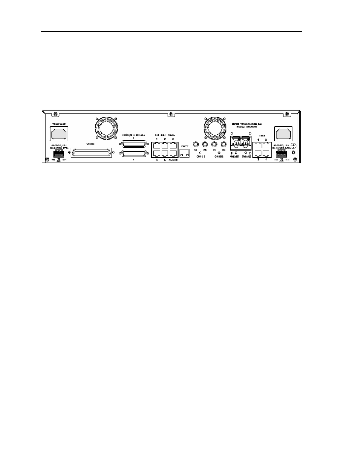
The power inputs are to the right and left rear of the IM ACS-200, and label ed according ly. In
Figure 1-2, the supply inputs are seen on the sides of the rear panel.
Model No.
Figure 1-2.IMACS-200 Rear Panel
Notes:
1. The two -48VDC and 125VDC feeds are located in the lower-left and lower-right hand
corners of the IMACS-200 rear panel. Based on ordering options, these ports will arrive
at the customer site with screw-down terminals contained in an accessory bag in the
IMACS-200 packaging. For cus tomers who order the single- supply option, the ri ght-hand
connector above (nearest the T1/E1 and ground screw) should be used. These three-pin
terminals (if s o equip ped) ar e labe lled left- to-r ight a s NC ( No Connect ion), -48 or 125 a s
the case may be, and RTN (return).
2. The two 120VAC and 220VAC feeds are located in the upper-left and upper-right hand
corners of the IMACS-200 rear panel. Based on ordering options, these ports will arrive
at the custo mer site with AC jacks installed. Simply place a North-American AC po wer
supply cord into the supplied jacks.
3. The IMACS-200 comes with two fan units installed in the unit. These fans will turn on
and off automatically as the temperature fluctuates inside the enclosure. These fans are not
field serviceable, and will alarm should one of them fail or become obstructed.
A more detailed descrip tion of this chassis and its power ca pabilities is given in chapter 3.
1-2 System Overview
Page 27

System Installation Introduction
Chapter 2
System Installation
2.1 Introduction
This chapter provi des inst ruction s for unpa cking and i nstall ing the I MACS-200 chassi s at the
user site. It also includes other information you will need to properly install the system and
refers you to other chapters for additional port-level information.
The system can operate on either AC or DC power when equipped with the proper power
supply. Refer to the system specifications section in this manual regarding
environmental requirements.
electrical and
2.2 Chassis Installation
2.2.1 Unpacking the Chassis
When you receive your system , unpack the box and chec k the contents for da mage. Inside the
box you should have the following three items:
1. The IMACS-200 system
2. A CD ROM with the documentation for the latest or ordered release.
3. A poly bag including the mounting hardware and power cord(s) and or connector(s).
If any of the items above are missing, please contact your sales representative. If anything is
damaged, contact the shipping carrier to file a claim. The carrier representative will also tell
you how to submit a claim, where to s end t he unit, and give you any specia l i nst ruc ti ons you
may need.
Pack the damaged item in its original packing materials and send it by prepaid freight to the
address you received. If the original packing materials are unavailable, pack the unit in a
sturdy box and surround it with shock-absorbing material.
System Ins t allation 2-1
Page 28

Running Head
Chassis Installation System Installation
Model No.
2.2.2 Pre-Installation Tips
2.2.2.1 Installation Checklist
Install your IMACS-200 in the following sequence:
1. Choose a suitable location for the system, as described in this chapter.
2. Unpack and inspect the equipment for damage.
3. Mount the chassis on the desired surface (rack, tabletop, or wall).
4. Install the chassis ground connections.
5. Verify the voltage ratings of all power supplies in the chassis.
6. Verify the fuse ratings of the source power supply.
7. Apply power to the system and verify the power LED states.
After successfully installing the system, configure the system for operation as follows:
1. Connect a VT100-compatible terminal to the Interface port.
2. Log into the system.
3. Set the Alarm Filters.
4. Configure the CPU interface along with the ethernet port if desired.
5. Configure the Voice ports.
6. Configure the Data ports.
7. Configure the WAN ports.
8. Configure all other ports.
2.2.3 Choosing a Location for Your System
The IMACS-200 requires a re asonably dust-free , static-free ope rating environment. Adeq uate
ventilation is also req uired at the sit e. Do not inst all t he chass is in direct sunli ght, which may
increase the system’s operating temperature and affect its operation.
Most of the system plug-in por ts have hig hly sens itive compo nents that could be damage d by
static electric ity. Whenever you handle any system p orts, be s ure to obse rve local electrost atic
discharge (ESD) precautions.
The system chassis can be installed on an 19-inch or 23-inch equipment rack, or placed on a
tabletop or other level surface. First though, make sure the desired surface can support the
weight of a chassis.
2-2 System Installation
Page 29

System Installation Chassis Installation
Be sure to locate the system near all external equipment to which you will connect it. Cable
lengths and physical/electrical characteristics are critical to system operation, especially for
data signal interfaces. Generally, higher data rates require shorter cables than lower data rates.
Also, you must use T1-grade cables for all system connections to those networks. For best
results, use the cables supplied by your supplier when connecting your system to the
associated external facilities. For more information on system cabling, call your supplier.
2.2.3.1 Rack Installation Tips
When installing the chassis in a rack, allow at least 2 inches (5.1 cm) of space between the
chassis and the equipment in front and behind it for proper ventilation. Use the mounting
brackets and attachment hardware furnished with the chassis for this purpose, as outlined in
this chapter. If you use other mounting hardware, you may damage the chassis or circuit
boards installed in it.
Also route all cables to their destinations through conduits to enhance electromagnetic
compatibility (EMC) per formance and facilit ate future system troub leshooting. When ro uting
cables, be sure not to obstruct any chassis vents.
2.2.3.2 Tabletop Installation Tips
The chassis can be pl aced on a flat, s moot h surf ace ( e.g., a tab le) tha t is free of con taminan ts .
This surface should be capable of supporting the chassis.
If you are placing the chassis on a tabletop or other flat surface, be sure to leave enough
clearance for a ir circulati on throug h the syste m. Make sure the chassis is accessibl e from both
the front and rear.
2.2.4 Installing the Chassis
Figure 2-1 shows the front panel of the IMACS-200 chassis. To mount the chassis in a rack,
first attach the brackets to the sides of the chassis, using the four associated 10-32 x 1/4”
screws. The brackets are reversible for mounting in 19-inch or 23-inch racks (48.2 or 58.4
cm). For a 19-inch r ack, at tach t he lo ng s ides o f the bracke ts to the ch ass is (F igure 2-2 sho ws
the mounting brac ket s and holes). For a 23-inch rack, att ach the short si des of t h e br ac ket s to
the chassis. You can attach the brackets to either positi on on the side of the ch assis. See Figure
2-3 on page 2-5 for a view of t he side panel of the IMACS-200 .Then, use the f our 12-24 x 1/ 4”
screws to mount the bracketed chassis on the rack.
System Ins t allation 2-3
Page 30

Running Head
Chassis Installation System Installation
Figure 2-1.IMACS-200 Front Panel
Model No.
Figure 2-2.Mounting Bracket Holes
The chassis have eleven holes on each side, as shown in Figure 2-3. Eight of these holes
facilitate mounting in a 19- or 23-inch rack (48.2 or 58.4 cm). You can attach the front, or
middle of this chassis to a rack, using the mounting brackets as previously shown.
2-4 System Installation
Page 31

System Installation Connector Types
Figure 2-3.Chassis Mounting Holes
Table 2-1 outlines the minimum clearance that is recommended for the IMACS-200 on all four
sides.
Table 2-1. Minimum Chassis Clearances
Clearance Front Rear
Inches 10 10
Centimeters 25 25
2.3 Connector Types
The product is equippe d with several types of electrical conn ections to the net work and power
sources. Table 2-2 lists the connections on the front pan el of the IMACS-200 (Refer to Figure
2-1 on page 2-4 for an illustration of the IMACS-200 front panel). These connections are
available for the cra ft s per so n to gai n eas y acc ess into the unit. Table 2-3 lists the back panel
connectors along with their functionality. (Refer to Figure 2-4 on page 2-5 for an illustration
of the IMACS-200 back panel)
Figure 2-4. IMACS-200 Rear Panel
System Ins t allation 2-5
Page 32

Running Head
Connector Types System Installation
Model No.
Table 2-2. Front panel connectors
Connector Name Connector Type Description
Ethernet RJ45 Ethernet port for remote management over IP.
Serial RJ45 Asynchronous craft port for local management.
Table 2-3. Back panel connectors
Connector Name Connector Type Description
Voice 50 pin amphenol Four E&M lines, transmit onl y ( to) i n the i ntro duct o ry offering of the
IMACS-200. Each line utilizes eight leads from the connector.
Voice 50 pin amphenol Four FXS Tip-and-Ring pairs. Each line utilizes two leads from the
connector.
Voice 50 pin amphenol Alarm input contacts are provided in this connector. There are four
available contacts, each utilizing two leads from the connector.
Alarm RJ45 Alarm outputs to an external alarm system.
High Speed Data DB25 female Two V.35 high speed data port connectors.
Sub Rate Data RJ45 Five subrate data (SRU) ports
OHSU1 and
OHSU2
Enet RJ45 Ethernet port for remote managemen t over IP. This port is disabled for
T1/E1 RJ45 Four transmit and receive pairs for T1 network access. E1 will be
48VDC (+-G) 1.5A
Max
125VDC (label)
120/220VAC AC receptacles Power input 1.0A 50/60Hz when external AC voltage is used to
OWAN1 OWAN2
Two ST optical
connector pairs
3 position
(plugs included
with kit of parts)
Two ST optical
Connectors
Earth Ground
The IMACs-200 can be configured with an Optical High Speed Unit
with two pairs of optical connections.
this initial release of the product.
provided in a later release.
For DC power inputs. IMACS-200 can have two DC inputs.The
cables used to connect the power to the chassis should be 20 to 18
gauge solid wire.
power the unit.The IMACS-200 can have two such supplies.
The IMACs-200 can be configured with an Optical WAN Unit with
two optical connections.
Permanent Earth Ground Connection.
Use 14 gauge solid wire for
a single connection to the provided earth ground screw, and
connect to a ground source.
2-6 System Installation
Page 33

System Installation Connector Pin-outs
2.4 Connector Pin-outs
Following is a description of the various connectors and their respective pin-outs.
2.4.1 High Speed Data port connec tor pinouts
T abl e 2-4 des cribe s the si gnals and pins for the V.35 data ports. The pin assignments are associ ated with
the use of Zhone cable part number 1216M (F).
Table 2-4. V.35 DB25 female connector
Pin Signal Source V.35 (with PRM-1261F cable)
1Shield A
2 Transmit Data A DTE P
3 Receive Data A DCE R
4 Request to Send DTE C
5 Clear to Send DCE D
6 Data Set Ready DCE E
7Ground B
8 Receive Line Signal Detector DCE F
9 Receive Timing A DCE X
10 External Transmit Clock B
11 Terminal Timing B Not Used
12 Tran smit Timing A DCE AA
13 Not Connected
14 Transmit Data B DTE S
15 Tran smit Timing B DCE Y
16 Receive Data B DCE T
17 Receive Timing B DCE V
18 Not Connected
19 Not Connected
20 Data Terminal Ready DTE H
21 Remote Loopback DTE N
22 Local Loopback DTE J
System Ins t allation 2-7
Page 34

Running Head
Connector Pin-outs System Installation
Model No.
Table 2-4. V.35 DB25 female connector
Pin Signal Source V.35 (with PRM-1261F cable)
23 External Transmit Clock A
24 Terminal Timing A Not Used U
25 Test Mode DCE NN
Note: For purposes of connection and function, the IMACS-200 should be considered a DCE.
2.4.2 E&M, FXS and Alarm input connector
Table 2-5 lists the connector pinouts for the E&M circuits, FXS circuit and the provided alarm input
points. For E&M, “R”, “T” and “M” are consider input direction, “R1”, “T1” and “E” are considered
output direction, and “SB” and “SG” are considered direction-neutral.
Table 2-5. 25-pair female amphenol connector
Port Designation Pin Port Designation Pin
E&M
Port 1
E&M
Port1
E&M
Port 1
E&M
Port 1
E&M
Port 1
E&M
Port 1
E&M
Port 1
E&M
Port 1
T-1 26 E&M
Port 4
R-1 1 E&M
Port4
T1-1 27 E&M
Port 4
R1-1 2 E&M
Port 4
E-1 28 E&M
Port 4
M-1 3 E&M
Port 4
SG-1 29 E&M
Port 4
SB-1 4 E&M
Port 4
T-4 38
R-4 13
T1-4 39
R1-4 14
E-4 40
M-4 15
SG-4 41
SB-4 16
E&M
Port 2
E&M
Port 2
2-8 System Installation
T-2 30 FXS
Port 1
R-2 5 FXS
Port 1
T-1 42
R-1 17
Page 35

System Installation Connector Pin-outs
Table 2-5. 25-pair female amphenol connector
Port Designation Pin Port Designation Pin
E&M
Port 2
E&M
Port 2
E&M
Port 2
E&M
Port 2
E&M
Port 2
E&M
Port 2
E&M
Port 3
E&M
Port 3
E&M
Port 3
E&M
Port 3
T1-2 31 FXS
Port 2
R1-2 6 FXS
Port 2
E-2 32 FXS
Port 3
M-2 7 FXS
Port 3
SG-2 33 FXS
Port 4
SB-2 8 FXS
Port 4
T-3 34 ALM
1A
R-3 9 ATM
1B
T1-3 35 ALM
2A
R1-3 10 ALM
2B
T-2 43
R-2 18
T-3 44
R-3 19
T-4 45
R-4 20
Alarm
contact
Alarm
contact
Alarm
contact
Alarm
contact
46
21
47
22
E&M
Port 3
E&M
Port 3
E&M
Port 3
E&M
Port 3
E-3 36 ALM
3A
M-3 11 ALM
3B
SG-3 37 ALM
4A
SB-3 12 ALM
4B
NC Not Used 50
NC Not Used 25
Alarm
contact
Alarm
contact
Alarm
contact
Alarm
contact
2.4.3 T1 interface RJ45 connector
Table 2-6 lists the T1 RJ45 connector pinouts.
48
23
49
24
System Ins t allation 2-9
Page 36

Running Head
Connector Pin-outs System Installation
Model No.
Table 2-6. T1 connector pinouts
RJ-45(F) Pin Signal
1R1
2T1
4R
5T
3, 6, 7, 8 Not assigned
2.4.4 Ethernet connections
Table 2-7 lists the RJ45 connector pinouts for the ethernet ports on the front and rear of the chassis.
Table 2-7. Ethernet connector pinouts
RJ-45(F) Pin Signal
1TXP
2TXN
3RXP
4TXCT
5RXCT
6RXN
7Not used
8Ground
2.4.5 Sub Rate Data Port s
Table 2-8 lists the RJ45 connector pinouts for the five sub rate data ports on the rear of the chassis.
Table 2-8. Sub Rate Data (SRU) ports connector pinouts
RJ-45(F) Pin Signal Direction
1SCTOutput
2 RLSD Output
3SCROutput
4Ground
5 RXD Output
2-10 System Ins t allation
Page 37

System Installation Connector Pin-outs
Table 2-8. Sub Rate Data (SRU) ports connector pinouts
RJ-45(F) Pin Signal Direction
6 TXD Input
7CTSOutput
8 RTS Input
2.4.6 Alarm Output Connector
The IMACS-200 is equipped with an RJ45 connection on the rear faceplate labelled ALARM to drive
external alarm responders such as buzzers, bells, and lights. Table 2-9 indicates the pin-outs for this
RJ45 connector.the T1 RJ45 connector pinouts.
Table 2-9. Alarm Output Connector pinouts
RJ-45(F) Pin Signal
1Alarm Output 1C
2Alarm Output 1
3Alarm Output 2C
4Alarm Output 2
5Alarm Output 3C
6Alarm Output 3
7Alarm Output 4C
8Alarm Output 4
2.4.7 Serial port - Craft Interface
The IMACS-200 is equip ped with an RJ45 connecti on on the front faceplate labelled SERIAL to allow
crafts person access to the IMACS-200 at all times.
Table 2-10. Serial port interface connector pinouts
RJ-45(F) Pin Signal
4Ground
5 Receive
6Transmit
1,2,3,7,8 Not used
System Ins t allation 2-11
Page 38

Running Head
Connector Pin-outs System Installation
Model No.
2.4.8 Connecting Cables to the ports
Connect system ports to the external equipment, using the proper cables. The ports have
various types of connectors for those connections.
Voice ports have a 50-pin Amphenol-type jack. To connect a cable to this type of jack, first
plug the male connector of the ca ble into t he jac k and push it in a ll th e way. Then, tighten the
mounting screws on either end of the cable connector shroud to the IMACS-200 connector.
For modular (RJ-45) jacks, push the cable’s mating plug into the ja ck until it sna ps in to place .
However, do not try to force th e plug into t he jack.
For DB-25 jacks, first plug the cable’s mating connector firmly into the jack. Then, thread the
screws on either s ide of the ca ble connector shroud into t he standof fs on eit her side of t he port
jacks, and hand-tighten them.
For a list of available cables for the IMACS-200, refer to Table 2 in the Product Description
section in the front of this user guide.
2-12 System Ins t allation
Page 39

System Installation Power and Grounding on the IMACS-200
2.5 Power and Grounding on the IMACS-200
2.5.1 Power Supply and Ringing Generator
The power supply and ringing genera tor syst em can consi st of up to two power supp lies, and
has one on-board ringing generator. The IMACS-200 comes with the proper power supplies
factory-assembled depending on the ordering information provided at the time of purchase.
2.5.1.1 Ringing Generator
The Ringing Generator on the IMACS-200 outputs 86Vrms at 20Hz. That is the output if
ringing into a 1 to 4 REN load. If the load increases, the built-in overload protection will
reduce the output voltage in steps as shown in Table 2-11.
Table 2-11. Ringing Generator Load Versus REN
Load[1REN =
Output Ringing Amplitude
86 Vrms 4REN
75 Vrms 5REN
70 Vrms 6REN
60 Vrms 8REN
50 Vrms 10REN
45 Vrms 12REN
Short Circuit Protection Active >>12REN
This ability inherent i n the IMACS-200 provides cont inuous service up to 12 North American
REN loads without distortion.
Following is more detailed information regarding the power inputs.
6930Ohms and 8
picoFarads]
System Ins t allation 2-13
Page 40

Running Head
Power and Grounding on the IMACS-200 System Installation
Model No.
2.5.2 System Power (Redundancy)
The IMACS-200 provides power redundancy for any of the powering options. The supplies
are factory-in stalled, and t he external co nnectors to re ceive the power ing options sel ected will
be pre-installed on t he unit. Figure 2 -4 on page 2-5 high- lites the locati on of the Power Suppl y
feeds.The 120VAC and 220VAC power inputs are lightly shaded, and the -48VDC and
125VDC options are darkly shaded.
2.5.3 AC Power Supply and DC Power Supply Fuses
The AC power supply and DC Power Supply fuses are alread y bui l t i n t o t he supplies. These
fuses are not field servi ceable. When unpacki ng the unit, an AC power cord will be in the box
for each of the AC power supplies ordered. The AC inlet connector is located in the rear
corners of the chassis. For a single supplied unit, the rear right-hand connector will be
equipped. Refer to the system specifications section in this manual for input power
requirements.
2.5.4 System Power and Ground Connections
After installing the system, make the power and ground connections to the chassis as
described in this s ection. A frame gr ound connection i s provided in th e right-rear corner of the
IMACS-200 rear panel.
2.5.5 Grounding requirements
Due to the UL regula tory re quiremen ts, a mounting stud is requi red f or con necti on of t he AC
input earth ground lead to the product chassis. The ground lead must be connected to the
chassis using a No. 6 screw, which is included. When grounding the system, use 14 gauge
solid wire for a single connec tion to the provi ded eart h grou nd screw. The mounting location
is labeled with the IEC 417 No. 5019 symbol to identify this as the AC earth ground
connection point. This mounting stud is located next to the IEC 320 AC input connector.
2.5.6 Chassis with Power Supplies
Figure 2-4 on page 2-5 shows the different power connections on the chassis.
For DC powered systems, the lower right and lower left-hand connections provide for
separate, redundant power feeds to the system's pre-installed DC power supplies if so
equipped. These two sets of leads provide a connection for separate, redundant power feeds
to the system in a load-sharing mode.
2-14 System Ins t allation
Page 41

System Installation Power and Grounding on the IMACS-200
The telecommunications voice signaling ground is a referenced ground connection to the
-48VDC power system. Both feeds are referenced to the same place within the IMACS-200.
This reference ground can occur at the -48VDC power source. If the ground connection is
not maintained, and one side of the connection equipment is not referenced to an earth
ground then a floating ground condition can occur causing the voice circuits and the
voice signaling to react erratically when either end of the connecting equipment tries to
start the circuit.
Sites using only lo op start telecommu nication circu its (no ground star t or E&M signaling) ca n
operate properly without the Telecom Signaling Ground.
When grounding the system, use 14 gauge solid wire for a single connection to the provided
earth ground screw.
For AC powered systems, t he right and left -hand con nections provide f or sep arate, re dundant
power feeds to the system's pr e-install ed AC power supplies if so equ ipped. These two sets of
leads provide a connection for separate, redun dant power feeds to the syste m in a load-shar ing
mode.
2.5.7 DC power instal l atio n
When wiring to an exter nal power source, such as a batte ry rack, fuse pa nel, or circuit breaker ,
make sure that the correct rating of wire is used . Figure 2-5 illustrates the DC power plug. It
is recommended that you use 20 to 18 gauge solid wire.
Figure 2-5. DC Power plug
When the IMACS-200 is ordered with a si ngle-power supp ly unit, the IMACS-200 will come
with the power supply installed on the right-hand rear of the box, closest to the T1/E1 ports
and grounding screw. Insert the power plug illustrated above into this right-hand rear
connector.
System Ins t allation 2-15
Page 42

Running Head
Power and Grounding on the IMACS-200 System Installation
Model No.
2.5.8 AC power instal l atio n
If ordered as an AC unit, the IMACS-200 will come pre-assembled with one or two AC
connectors on the rea r panel , a s illust rate d in Fi gure 2- 4 on page 2- 5. To apply the AC source
to the unit, simply use the supplied AC cords included in the packaging to connect the
IMACS-200 to the 120VAC or 220VAC source.
2.5.9 Powering Up the System
After connecting the chassis to the external power sources and making the proper ground
connections, apply p ower to the chassis. Plug the AC power cord int o the assoc iated elec trical
outlets, or turn on the external DC power supply. Then, observe the following front-panel
LEDs:
1. On start-up, all LEDs on the front and rear of the unit cycle through the following color
sequence:
Orange, Green, Red and blank.
2. The POWER LED then wil l turn gr een on the chassis faceplat e. The ACTIVE LED will
stay orange until the unit boot cycle is completed, and then turn green.
If no LEDs illuminate, verify that the external power source is providing power to the chassis,
and check the connection between that source and the chassis.
Once power is confirmed, the user in terface sh ould appear. If not, simply hit carr iage return.
A window like Figure 2-6 should appear. Type i n the user n ame of “admin”, and t he password
is “admin”.
Figure 2-6. IMACS-200 Initial Login Screen
2-16 System Ins t allation
Page 43

System Configuration and Operation Basic Operations
Chapter 3
System Configuration and Operation
3.1 Basic Operations
This chapter provides instructions for configuring the IMACS-200 for operation after
installing it at the equipment site.
Before performing the procedures in this chapter:
1. Be sure your IMACS-200 is installed and powered up.
2. Determine your system’s specific configuration requirements. These depend on your
network and customer premises equipment (CPE) interfaces. If this configuration
information already exists, obtain it from your system administrator or engineers.
3. Obtain a terminal with VT-100 or VT-102 emulation and an RS-232 to RJ45 serial cable
for these procedures. The terminal will be connected directly to the SERIAL port on the
front faceplat e of your system. T his will allow you to access the system and t hen configure
it for operation with your network and CPE.
Refer the Table 2-10 on page 2-11 for pinouts for RS-232 and SERIAL port.
3.2 Basic Screen Map and Legend
To make system access, configuration and testing easy, the system presents you with a series
of user interface screens. Each screen displays various fields of information, and you can
change the data in those fields as required by your system and external interfaces.
3.3 System Power -up
The IMACS-200 system will initialize when it is powered up. The normal sequence for
initialization and login are described on the following pages.
System Operation 3-1
Page 44

Running Head
System Power-up System Configuration and Operation
Model No.
3.3.1 System Boot
Following the application of power, proceed as follows:
1. Be sure your system and local terminal are both powered up.
2. Connect a VT100-compatible terminal to the SERIAL jack on the faceplate of the
IMACS-200 front panel. Use a cable with an RJ-45 modular plug on one end for this
connection.
3. Configure the terminal to operate at 9.6 kbps, 8 data bits, no parity, and 1 stop bit.
Should your SERIAL cable be connected prior to powering the IMACS-200, or should
power be removed and re-applied to the IMACS-200 during this process, the following
screen will appear:
Figure 3-1.Testing and Initialization Screen
4. Press the RETURN key. The Login Screen appears.
The system will display Figur e 3-1 above. When testing and in itializing is comple te the screen
will go blank. Pr ess the <Enter> key. The System Login Screen will displ ay, as seen in Figure
3-2
3-2 System Operation
Page 45

System Configuration and Operation System Power-up
3.3.2 Logging Into the System
The first step in start i ng a user session is to log into the system. You must enter a password
that allows you to perform the required tasks on the system. For access levels and user
permissions, refer to the section de ta il ing user access in Section 4.3.2 on page 3 of Chapter 4
IMACS-200 General Features.
T o log into the system from a lo cal ter m in al, proceed as follows. To log in from a remote PC
refer to details later in this reference manual.
1. Press <Enter>. The Login Screen depicted in Figure 3-2 should appear. If not, press
<Enter> again until it does.
2. If the Login Screen does not appear after you press <Enter > se ver al t ime s, che ck your
terminal settings (they should be 9.6 kbps, eight data bits, no parity, and one stop bit).
Figure 3-2.Typical Login Screen
3. Contact your system administrator for your Username and Password. Enter your
Username, and press either the <en ter> or <tab> key . Then en ter your Password and press
RETURN to accept the password, which will allow you to configure your system after
logging in for the ver y first time. Ref er to Section 4.3.2 on page 3-3 for des criptions of th e
various user levels.
4. Should you be the system administrator, the default Username is admin and the
password is admin. As this constitutes a Superuser access, it is highly recommended that
this default passwor d be changed to preven t unauthorized ac cess and enhance th e security
of the IMACS-200. Refer to Sect ion 4.3.2 on page 3 of Chapt er 4 for f urthe r informat ion.
System Operation 3-3
Page 46

Running Head
System Power-up System Configuration and Operation
5. Once system access has bee n obt ai ned, t he I MACS 200 will prompt the user to assign
WAN and OWAN (if provisoined) port defaults. All four of the WAN or OWAN ports
must be set to the same interface type (T1 or E1). This main screen is shown in Figure 3-3.
Currently, the OWAN and WAN must be set to the same interface type, either E1 or T1.
Caution should be exercised when choosing the interface type to the WAN and OWAN.
All four ports avai lable to the interfac e must be set to the sa me type, and changing th e type
will require a reboot of the system software, dropping all services. Prior to the change, all
existing services and WAN / OWAN ports must be in the standby state.
Model No.
Figure 3-3.WAN and OWAN Interface Un-provisioned Setting
Once the WAN and OWAN Types have been set as either T1 or E1, the user must save the
setting. This will prompt a reboot of the IMACS 200, and once completed then the typical
login screen will appear, as seen in step 6.
6. The System Main Screen appears. Figure 3-4 shows this screen.
3-4 System Operation
Page 47

System Configuration and Operation System Power-up
Figure 3-4.Typical System Main Screen
This completes the login process. If you are not familiar with the user interface screens of the
system, read the next section before proceeding. Otherwise, continue with the desired
operation.
System Operation 3-5
Page 48

Running Head
System Screens System Configuration and Operation
Model No.
3.4 System Screens
The system screen will display each port that is currently installed onto the system along with
the port status and location.
3.4.1 System Main Screen
After you log in, a Sy stem Main S creen Figu re 3-6 appe ars, showin g all o f the ports c urrentl y
in the system. The port types and current port operational states also appear in this screen.
The highlighted line at the bottom of the screen lists some actions. Press the letter key that
corresponds to the desired action you want to perform. For example, to go to the Alarms
Screen (Alarms action) and see t he curr ent sy ste m alarms , press “ a” ( can be ty ped in ei ther
uppercase or lowercase). Table 3-1 summarizes th e System Main Screen actions.
Table 3-1. System Main Screen Actions
Action Function
Alarms Brings up the Alarm Screen. Refer to "Alarms and Alarm Filters” later in
this chapter.
Xcon Brings up the cross-connect screens.
sYstem Brings up the system screen for high-level system testing and maintenance.
Logout Logs you off the system.
Oos Allows authorized operators restar t the unit.
3.4.2 Voice and Data Port Status
The System Main Screen also displays the status of the individual circuit ports of all WAN,
Voice and Dataports in the system. This information appears next to the port type, as shown
in Figure 3-5. The lowercase letters in the Status column fields indicate the states of the
individual port ports. The possible values for each port are s (Standby), a (Active), t (Test),
and l (currently in a Loopback state).
3-6 System Operation
Page 49

System Configuration and Operation System Screens
Figure 3-5.Typical port Status Display
From the System Main Screen, you can also access other screens, as shown in Figure 3-5.
These screens are described in the following paragraphs.
3.4.3 Service Type Main Screens
Each port type in the system has a port Main Screen associated with it. You can go from the
System Main Screen to any port Main Screen and configure that device. From a port Main
Screen, you can access a Test Screen to perform tests on the port, or (in some cases) a
Performance Monitor Screen to view transmission performance data.
Figure 3-5 shows the main scree n of t he IMACS-2 00 and refle cts the port stat us. On t he FXS
line, the user will note the four different ports, and that each port is in a different state. Port
one is on the left, and port fou r is on the ri ght. The figur e dis plays ‘aslt’ as the status of ports
one through four, which are: port 1 is in active state. Port two is in standby state, which is to
say it is out of service.Port three is in the loopback active state, in other words it is currently
involved in a user-initiated maintenance mode. And finally port four is in a test state, which
is a user-initiated testing mode. These states are used commonly on all the different service
types, and are a quick reference for the status of each port.
Figure 3-6 shows a typical port Main Screen. The highlighted line at the top of every screen
is the header. It lists the node name of the system, the current port type and abbreviated
description, the port design revision and serial number, and the current system date and time.
System Operation 3-7
Page 50

Running Head
System Screens System Configuration and Operation
The port configuration parameters and current option settings appear in numerous rows and
columns below the header. This region of each screen lists the options on the left and one or
more associated co lumns of da ta fiel ds from l eft to ri ght. You can change the settings in those
fields as required for each port.
The status and data entry chan ge line appears just above the bott om li ne of the screen. When
you choose a field to edit and press <Enter>, this line shows the currently available option
settings for that field. Make all configuration changes on this line.
Model No.
3-8 System Operation
Page 51

System Configuration and Operation System Screens
The highlighted area in the upper right corner shows the current alarm status data. In Figure
3-6 below, a yellow alarm has occurred on WAN port 4, and a Loss of Signal al ar m has been
detected on WAN port 3.
Figure 3-6.Typical port Main Screen
The bottom line of each port Main Screen lists other actions you can perform by simply
pressing the lett er key that correspond s to the uppercase lett er of your desired act ion. In Figure
3-6, for example, if you pr ess “s”, you will invoke th e Save command, which saves the current
option settings in the sys tem’s memory. The act ions yo u can choose from this line dep end on
which port and screen you are currently accessing. Refer to the associated chapters in this
guide for descriptions of those actions.
System Operation 3-9
Page 52

Running Head
Port Configuration System Configuration and Operation
Model No.
3.4.4 Test and Debug Screen
You can also go from the System Mai n Scre en to a Test and Debug Screen, which allows you
to perform system-level maintenance operations. You can back up the system configuration
onto an external compu ter aft er savin g and subse quently e diting i t, and ( if neces sary) you can
restore that configuration to the system. You also can erase the system configuration and
restart the system with a single “zip” command.
The system software also has a built-in debugging utility. However, this utility is only
available to factory software engineers. The system maintenance functions are described in
the “Testing and Debugging” section later in this chapter.
3.5 Port Configuration
3.5.1 Selecting and Configuring Your ports
The System Main Scre en lists all system ports. You can access any port from the Ma in Screen
by moving th e cursor in the installed interfaces column with the arrow keys until the desired
port is highlighted, then press <Enter>. The associated port Main Screen now appears. The
only optional installed interface on the IMACS-200 is the Optical High Speed Data Unit
(OHSU).
Use the arrow keys to move the cursor around in any port screen. When changing port
parameters, some setti ngs requi re you to e nter your own v alues on the keybo ard, while oth ers
allow you to select from a list of pre-programmed option settings.
T o en ter a use r- defined v alue in a field, first h ighli ght that field b y moving the curs or to it and
press <Enter>. The n, type the desir ed val ue on your ke yboard and pr ess <Ente r> to stor e it in
that field.
T o choose an option s etting fr om a list of display ed options, press <Ente r> with t he associat ed
parameter field highlighted. A series of available option settings now appears for that field.
Use the right-arrow and left-arrow keys to move the cursor to the desired setting, and press
<Enter> to store that setting in the highligh ted field.
Be sure to configure each port according to your net wor kin g requirements. From the System
Main Screen, select each port in turn and change the options for that port from its Main Screen.
Select the Save command by pressing “s” after making all the changes for a port, then press
“m” to return to the System Main Screen and choose another port. Similarly configure each
remaining port in your system.
Once configured, the port settings are permanently stored in Non-Volatile Random Access
Memory (NVRAM).
3-10 System Operation
Page 53

System Configuration and Operation Port Configuration
3.5.2 Recording Your Configuration Settings
You should always record the configuration option settings for each port after you set them.
This information may be needed later for system operation. To record the port configuration
data, first photocopy the pages showing the port Screens in the associated chapters of this
guide. Then, mark the opti on setti ngs you want to use on those p ages, and st ore the page s in a
safe place where they can be readily obtained.
You can also record screen settings by “capturing” each edited screen onto your computer
terminal while you a re logged into the system. To do this, your comput er must have a software
program capable of capturing the actual screens as text files. The communications software
you use to access the system may have this ability. You can then copy the screens to a word
processing program, print them out, and / or store them electronically.
System Operation 3-11
Page 54

Running Head
Reinitializing the System System Configuration and Operation
Model No.
3.6 Reinitializing the System
The system stores in formation about i ts currently inst alled ports, the port configura tion option
settings, WAN connections, passwords, and other data in nonvolatile memory (NVRAM).
When you change any settings on the port types, the NVRAM remembers the previous port
settings.
Restart capability is available on the IMACS-200. If the user desires to restart the
IMACS-200, capability is available on the main login screen with the Oos command. This
command will restart the box, as shown in Figure 3-7. preserving all provisioned data.
Figure 3-7.Rebooting the IMACS-200
If you have redeployed the IMACS-200, or otherwise desire to re-initialize the unit to the
default settings, you c an “zip” it , causing it to be reprog rammed. From the main login scre en,
enter ‘Y’ to go to sYstem. A screen such as what is seen in Figure 3-8 appears
3-12 System Operation
Page 55

System Configuration and Operation Reinitializing the System
.
Figure 3-8.System Screen - Test and Debug.
Once here, enter ‘Z’ to zip the system, and the screen seen in Figure 3-9 will appear.
Figure 3-9.Cold-Start NVRAM “Zip”Test and Debug Screen.
WARNING!
Confirming the "Z" command will start the ZIP process. "Zipping" the system deletes all of
the information stored on NVRAM and resets it. All ports must then be completely
reconfigured. When the zip is performed, user names and password data will be maintained.
System Operation 3-13
Page 56

Running Head
Alarms System Configuration and Operation
When you press “z”, the system will ask, "OK to Zip the syste m (y/n)"? Pres s “y” to have the
system test and re initialize itself. All NVRAM information will be erased from the
IMACS-200, and a new log-in screen will appear. Since the user names and passwords are
maintained over the zip function, the user will be able to login as normal. Also maintained
over the zip function are the IP address(es) saved in the unit.
Model No.
3.7 Alarms
Alarms warn you of problems by reporting possible system hardware or external facility
failures. The Alarm scree n is accesse d from the System Mai n Screen by press ing the "A" key
to go to the Alarm Scr ee n ( se e Fi gur e 3-10 through Figure 3- 12) . The Al arm Screen displays
the currently activ e alarms (if any) and p rovides access to th e Alarm Filters and Ala rm History
screens. Figure 3-10 shows a typical Alarm Screen with an active alarm.
3.7.1 Alarm Screens
Refer to Figure 3-10. To view the current system alarms, you ca n go from the System Main
Screen to an Alarm Screen. From the Alarm Screen, you can then go to an Alarm Filters
Screen and set up the alarm reporting filters. Or, you can access an Alarm History Screen (log)
and view alarms that we re previou sly logged by the sy stem. These sc reens and o peration s are
discussed in the “Alarm s and Alarm Filters” section later in this chapter.
Figure 3-10.Typical Alarm Screen
The first character set (00513 in the above display) is the Alarm Se quen ce Numbe r. This is a
sequential number from 1 to 65,535. It identifies the alarm for tracking and maintenance. In
the above example, the Alarm Sequence Number is 513.
The second character se t ( WAN-4) is the location of the problem. In this case, the WAN port
WAN-4 is affected and has reported the alarm.
3-14 System Operation
Page 57

System Configuration and Operation Alarms
The third character set is the alarm modifier (in this case, m indicates a minor alarm). See the
“Alarms and Alarm Filters” section later in this chapter for m ore informa tion about alarm
modifiers.
The fourth character set (YEL) is the type of alarm generate d (in this cas e, a Yellow alarm on
WAN port WAN-4).
The last two character sets are the date and time the alarm was logged.
System Operation 3-15
Page 58

Running Head
Alarms System Configuration and Operation
Model No.
3.7.2 Alarm Filter Settings
Y ou can set filt ers for each alarm so t hat the alarm r eports occu rrences in a number of dif ferent
ways. Figure 3-11 shows the Alarm Fil te rs scr ee n, whi ch i s a cce ss ed by pressing "f" (Filters
command) on the Alarm Screen.
Figure 3-11.Alarm Filters Screen
The first column of th e Alarm Filters Screen is the alarm abbreviation that appears when an
alarm is generated. The second column is the associated full name of each alarm. Table 3-2
describes each alarm appearing in the Alarm Filters Screen.
The third column contains the filters ignore, log, and report. Set the filter to ignore if you
want the system to ignore the alarm. Or, set it to log if you want the system to show the alarm
report on the screen and also log it in to the Alarm History, as described later in this cha pter.
Set the filter to report if you want the system to send (report) the alar m indication to a remote
device. Wi th this se ttin g, the syste m will also di splay the alarm re port on the screen and l og it
into the Alarm History.
The fourth column of th e Alarm Filters Screen contains the filter modifiers info, mi nor,
major, and crit. This column specifies a le vel of i mport ance ( informa tion o nly, minor alarm,
major alarm, or critical al arm) for eac h alarm. These settings are described la ter in thi s chapter .
The last column sets the alar m cutoff (ACO) to aco-off or aco-on. These settings are explai ned
later in this chapter.
The filter in the thi rd col umn take s prece den ce over its modi fier. If, for instance, you have a n
alarm filter set to ignore, the setting of the modifier as info, minor, maj or, or crit will be
ignored. Refer to system specifications section in this manual for alarms and their meanings.
3-16 System Operation
Page 59

System Configuration and Operation Alarms
Table 3-2. Alarm Filters
Filter Alarm Meaning
NOS No Signal Incoming WAN signal is lost.
LOS Loss of Synchronization Frame Alignment is lost.
YEL Yellow Alarm The system has rece ived a Yellow Alarm signal from a remot e device.
Usually receiv ed when the device loses WAN signal or synchronization.
AIS Alarm Inform ation Signal The system has received a Blue Alarm signal f rom a remote device. Usually
received when the remote or intermediate device has a major failure.
CGA_RED Carrier Group Alarm - Red The local incoming WAN signal has a serious problem and trunk
conditioning is started. After receiving a RED alarm (NOS or LOS) for 2-3
seconds, the system initiates the appropriate trunk conditioning sequence
(see voice ports for information about the TC_CGA setting) and sends a
Yellow Alarm to the remote device. If the system is in drop/insert mode, it
also sends an AIS signal to the downstre am equipment.
CGA_YEL Carrier Group Alarm - Yellow The system has initiated trunk conditioning in response to a Yellow Alarm
from a remote device. After 2-3 seconds, the system initiates the appropriate
trunk conditioning sequence (see voice ports for information about the
TC_CGA setting).
ERR Excessive Error Rate The error rate measured by the system has exceeded the threshold set on the
WAN port.
SENSOR Alarm port Sen so r The Alarm port sensor has received an alarm indica tio n from an attached
device.
HI-TEMP Temp e rature Alarm The IMACS-200 has exceede d it ’s ability to regu la te th e tem p e rature in the
unit, and external action is required.
FANFAIL Cooling Fan Failure One of the tw o sup pl ie d fan s has failed.
UCA User port/po rt alarm One or more active port s on a us er por t a re n ot wor king pr ope rly. Voice ports
will show an alarm for ex ce ss ive signaling transitions and data po rts will
show an alarm for ex ce ed in g th e data error threshold.
RESET System reset The system has been reset by either loss of power or by a system software
upgrade.
ACO Alarm Cut-Off The ACO option forces you to manu ally clear certain alarms. Without this
option, self-cor re ctin g a la rms mi ght no t b e n otic ed . Wh en th e ACO opt ion i s
set to either Report or Log and the modifier is set to Major, alarms will report
normally but will also generate an ACO alarm. If the modifier is set to Minor,
it will not generate the ACO alarm. If the filter is set to Ignore, no alarms will
be generated. This can depend on whether or not the IMACS-200 is set for
latch or cur .
SYNC Clock Sync Alarm The SYNC alarm is generated wh en eith er th e p rimar y o r sec on dar y ext er nal
clock source is lost. This alarm is in addition to the condition that lost the
clock source (CGA-RED or OOS).
WARNING!Alarm Modifiers
Each alarm may also be designated as I=info, m=minor, M=major or C=crit. The filter
modifier appears on both the active alarm and alarm history screens.
System Operation 3-17
Page 60

Running Head
Alarms System Configuration and Operation
When interfacing to t he Exte rna l Alarm po rts, t he occur rence of any al arm d esigna ted as crit
will trigger a form-C relay contact on the External Alarm port. The relay contact action sets
off an annunciator or lamp at the equipment site. Similarly, the occurrence of any alarm
designated as major triggers a di fferent conta ct and activates ano ther external indicato r . Refer
to the Alarm port Refere nce Guide fo r more information on the External A larm ports.
Model No.
3.7.3 Alarm Cutoff (ACO)
The ACO (Alarm Cutoff) s ecuri ty feat ure is used by the syste m to alert an op erato r to ala rms
that clear themselve s while the syste m is unattended. The ACO op tion settings a re aco-on and
aco-off. If ACO is set to report or log alarms, any alarm set to report or log with a major
modifier brings up an additional alarm message on the screen. You must manually clear this
message, which is the ACO alar m message (depe nds on whether or not IMACS-20 0 is set fo r
latch or CUR). The ACO is us ed with t he node por t of the Interf ace port. It can a lso tri gger an
external alarm device, such as a bell or lamp, that must also be manually cleare d.
All ACO alarms must be cleared from the Interface port screen. ACO alarms can be cleared
automatically or manually.
3.7.4 Alarm Handling
Alarms set to either log or report record occurrences automatically to the Alarm History
Screen. To view that screen, press “h” (History command) in the Alarm Screen. Figur e 3-12
shows a typical Alarm History Screen, in which you can update the log wi th any ne w ala rms
that occur. To do this, press “r” to select Refresh in the Alarm History Scre en. Or, to delete
all entries in the log, press “c” to select Clear in the Alarm History Screen.
The alarm log may contain more than one screen (page) of data. To scroll through the log,
press “u” or “d” (pgUp or pgDn) to move up one page or down one page at a time. The lat est
alarms appear at the beginning of the log, which is on the first page of the alarm log.
All alarms (except those set to ignore) appear in t he Alarms fi eld in the upper ri ght corne r of
the screen, regardless of their setting in the Alarm Filters screen. The display in the Alarms
field is an abbreviated version of the alarm name and location number. For example,
CGA_RED below indicates that WAN port 2 has had a Major red alarm.
3-18 System Operation
Page 61

System Configuration and Operation Cross-Connecting (XCON)
Figure 3-12.Typical Alarm History Screen
3.8 Cross-Connecting (XCON)
From the System Main Screen, you can access a Cross-Connect Screen by pressing “x”
(Xcon) that lets you cross-connect WAN time slots between T1 links. For a detailed
description of making conne ctions on and throu gh the IMACS-20 0, see Section 3.10 on page
25 for information regarding making and managing cross-connects.
3.9 System Level Maintenance
You can also go from the System Main Screen to a Test and Debug Screen, by pressing “y”
(sYstem) which allo ws you to perform system- level maintenance op erations. You can back up
the system configuration onto an external computer after saving and subsequently editing it,
and (if necessary) you can restore that configuration to the system (refer to the backup and
restore section later in this chapter). You also can erase the system configurat ion and restart
the system with a single “zip” command.
3.9.1 Test, Debug, Backup & Restore
Advanced configuration and diagnostics are available through the use of the sYs (sYstem)
command from the System Main Screen. Pressing “y” brings up the Test and Debug screen
shown in Figure 3-13.
System Operation 3-19
Page 62

Running Head
System Level Maintenance System Configuration and Operation
Figure 3-13.System Test and Debug Screen
Model No.
3-20 System Operation
Page 63

System Configuration and Operation System Level Maintenance
3.9.2 Debugging the System
The D (Deb ug) command is only avai lable to factory p ersonnel with a pa ssword authoriza tion
higher than "Superuser." It gives access to the system software coding.
3.9.3 Backing up the System Configuration Data
The IMACS-200 provides the capability to backup the system configuration to a PC or
network service device. This informati on will be contained in a file, and can be use d to restore
the data to the same u nit s hould i t eve r nee d to b e r e-in stall ed, or to us e the co nfigur atio n as a
base file to place into other boxes with the sam e configurat ion to save time on installation.
There are two options for backup and restore, as seen in figure Figure 3-14. TFTP and
xmodem file transfer protocols are employed on the box.
Figure 3-14.Backup (and restore) File Transfer Protocols
3.9.4 Pre-TFTP Backup and Restore Preparation
To perform backup and restore uploads/downloads via the TFTP function, the following
method of connection to a Local Area Network (LAN) network must first be selected.
1. The first option requires that the system to which you will download be powered and
running through an active ethern et port that i s connec ted to a LAN. The connect ion must
be made either in the box that will receive the downloaded or i n a remote box routed
through the local IM ACS-200 that is s et as a gatewa y using IP prot ocol. You must be able
to ping the IMACS-200 IP add ress from the P C or server tha t you intend t o use as a TFTP
server and vice versa . Setting up t he host IP address, netma sk and gateway a re done at th e
sYstem level, and then editing the parameters in the tcp/Ip screen as shown in figure
Figure 3-15 on page 3- 22. The Ho st IP S tat e mu st be set t o the activ e sta tus, a nd the Host
System Operation 3-21
Page 64

Running Head
System Level Maintenance System Configuration and Operation
I P and netmask parameters must be set. You may need to change the routing table on your
PC to include the IMACS-200 ethernet address as the gateway, or the local host address
as the gateway for the sy stem receiving the file as the destination IP address,
Model No.
Figure 3-15.Setting the Host IP address
Note: Your PC must have some sort of TFTP or TFTPD server software installed and
running when you are downloading the binary files to the system. If you are using
TFTPD type software it is easier if you set the root directory to indicate where the
binary file is located at the TFTPD root screen. This eliminates the need to enter a
path at the file name screen during the download pr ocess . I f you are running a TFTP
software package, consult the user guide accompanying the software for details on
configuring and using the software.
3.9.5 TFTP Backup for 1.x.x
Follow the instructions listed below to perform a TFTP backup.
1. Log into the Integrated Access System using the Manager Password.
2. Press “Y” for System at the main menu.
3. At the Test and Debug screen press “B” for Backup.
4. The NV Ram Backup screen will appear. If the Protocol selected is xmodem, pr ess Enter .
Y ou will b e shown the option of t ftp on the bottom of the screen. Use the rig ht or left arrow
key to move to tftp, and press Enter.
3-22 System Operation
Page 65

System Configuration and Operation System Level Maintenance
5. Press “G” for Go - an NV image overwrite command confirmation appears. Enter “Y”
for yes.
6. Confirmation appears when the NV Ram flash backup is complete. Press Enter as
prompted on the screen.
7. TFTP backup is now ready to proceed. Select TFTP by highlighting the appropriate
protocol using the arrow keys. Press Enter when TFTP is highlighted.
8. Press “G” for Go.
9. A series of four questions must be answered to complete the backup process. The
questions are as foll ows:
The system asks for the desired number of mismatch retries. Enter an appropriate number
between 1-40, with 20 as default. Press Enter.
The system asks for t he de sired numb er of Timeout Retries. Enter an appropr iate nu mber
between 1-10, with 4 as default. Press Enter.
Next, the system requires the IP address of the PC or TFTP server to which the backup
will be sent. Following entry of the IP address press the Return key to continue.
Finally, the system requires entry of the filename for the backup being performed.
Following entry of a filename the backup process begins. A TFTP backup complete
message appears when the process finishes.
Finally, the system requires entry of the filename for the backup being performed.
Following entry of a filename the backup process begins. A TFTP backup complete
message appears when the process finishes.
3.9.6 TFTP Restore for 1.x.x
Follow the instructions listed below to perform a TFTP restore.
Note: Restore actions may be denied, based on several factors. Should the database
being restored not be an IMACS 200 database, or if it comes from a higher
release then is currently running on the IMACS 200, or if the checksum of the
file does not match the calculated value, then u ser will be presented with a
message indicating 'Invalid NV flash image'.
1. At the main menu press “Y” for System.
2. Press “E” for Restore at the Test and Debug menu.
System Operation 3-23
Page 66

Running Head
System Level Maintenance System Configuration and Operation
3. Use the arrow keys to highlight the Protocol selection and press Enter.
4. Select TFTP and press Enter.
5. You will receive an NV Ram image overw rite confi r mation message. Press “Y” for yes.
6. Enter the desired number of Mismatch retries and press Enter.
7. Enter the desired number of Timeout Retries and press Enter.
8. Enter the IP address of the PC or TFTP server and press Enter.
9. Enter the filename for the ba ckup you wish to restor e and press Ente r . Restoration begin s.
10. Following completion of the restoration process, the system will prompt to restore data
with the image that was uploaded. Press “Y” for yes.
11. The system asks to reboot. Press “Y” for yes. The system reboots and configuration
becomes active.
Model No.
3.9.7 XMODEM Backup
Follow the steps listed below to perform an XMODEM backup.
1. Log into the Integrated Access System on which the backup is to be performed.
2. Press “Y” for System at the main menu.
3. When the Test and Debug screen appears, press “B” for Backup.
4. If the se lection currently indi cates TFTP, then press Enter.
5. Select xmodem using the arrow keys and press Enter.
6. Press “G” for Go. A confirmation appears upon completion of the NV Ram backup to
flash. Press Enter as prompted on the screen.
7. Prior to starting the backup or restore proc ess, ensure t hat have the PC emulation pac kage
is set to the XMODEM type format, otherwise an error will occur during the process.
XMODEM backup is now ready to proceed.
8. From the terminal screen select “Receive File” from the appropriate file menu. The
system prompts for a backup storage directory and filename. Following entry of the
appropriate information, backup begins. With most terminal emulation software (i.e.,
Hyperterminal, ProCom, or Smartcom) a status window will appear during the backup
process.
3-24 System Operation
Page 67

System Configuration and Operation Time Slot Assignment
9. A system backup completio n messa ge a ppears and the system then promp ts you to pres s
Enter to continue. The backup is now complete.
3.9.8 XMODEM Restore
Follow the steps listed below to perform an XMODEM restore.
Note: Restore actions may be denied, based on several factors. Should the database
being restored not be an IMACS 200 database, or if it comes from a higher
release then is currently running on the IMACS 200, or if the checksum of the
file does not match the calculated value, then u ser will be presented with a
message indicating 'Invalid NV flash image'.
1. Log into the Integrated Access System to be restored.
2. To restore a previous backup access the main menu. Press “Y” for System.
3. Press “E” for Restore at the Test and Debug screen.
4. If the se lected Protocol indicates TFTP, then press Enter.
5. Select XMODEM transfer method and press Enter.
6. Press “G” for Go to begin restore.
7. From the terminal emulation window select “Send File”. Enter the correct location and
filename of the backup to be restored and press Enter. Restoration should begin and a
progress monitor screen will appear.
8. Upon completion of the r estor ation , th e syst em prompts whether or not to re store the NV
Ram image, select “Y” for Yes.
9. The system prompts whether or not to reboot. Select “Y” for Yes.
10. Following system reboot, login as usual and proceed as appropriate.
3.10 Time Slot Assignment
This section provides instructions for assigning DS0 time slots to the voice and data ports of
the IMACS-200. It also provides time slot cross-connection setup instructions.
System Operation 3-25
Page 68

Running Head
Assigning Time Slots System Configuration and Operation
The IMACS-200 maximizes the use of incoming and outgoing T1 lines. You can do this by
assigning specific c hannels , or DS0 t ime sl ots , to voice and da ta por ts i n the syst em. You also
can cross-connect time slots between T1WAN ports of the system.
The WAN port allows you to connect one DS0 time slot to another. Throughout this chapter,
these connections ar e called "pas s-through" ci rcuits becau se they link a ti me slot from one T1
line to another thro ugh the syste m. You can therefore have up to four separ ate T1 links on two
WAN ports, in any cross-connect combination.
The following sections of this chapter describe several ways for you to administer your
networks and correctly al locate tr ansmission bandwidth to meet your needs. The nex t section
deals with assigning time slots to the user voice and data port.
The third section deals with cross-connecting WAN time slots to other WAN time slots.
The fifth section describes signaling status, signaling, and companding conversion. The last
section shows you how to view the time slot map after making your assignments and
cross-connections.
Model No.
This chapter defines "assigning time slots" as the process of connecting user port ports to
WAN ports and time slots, and it defines "cross-connecting time slots” as the process of
connecting WAN time slots to other WAN time slots in the system.
3.10.1 Modes of Operation
In the 1.x.0 system, the only mode available is XCON.
3.10.2 XCON Mode (XCON)
The XCON mode allows the user to cross-connect DS0s to user voice or data ports or to
cross-connect any DS0 on any WAN port to any DS0 on any other WAN port in the system.
The “Mode” setting on a WAN in a XCON system will only indicate the XCON option.
3.11 Assigning Time Slots
You must use a time slot map to specify the connections between all incoming and outgoing
lines connected to the system. The time slot map lets you split up your T1 bandwidth into
portions required for normal voice and data communications. It contains the connections for
all ports in your system.
3-26 System Operation
Page 69

System Configuration and Operation Assigning Time Slots
3.11.1 Assigning a Time Slot to a User port Port
You can define a time slot map from any user port (data or voice) for connections involving
that port, or from a WAN port for cross-connect ions involving only WAN ports. For example,
Figure 3-16 shows the E&M por t Main Screen for the time slot assignments. Assign t ime slots
to a voice port as follows:
1. From the System Main Screen, select the desired voice port and press <Enter>. That
port’s Main Screen appears.
2. Select the WAN port from which you want to assign time slots to the E&M port. In
Figure 3-16, this is wan-1 (for WAN 1, port 1).
3. Select a tim e slot (TS) for the first port. A number appears at the bottom of th e screen
for the corresponding time slot on the WAN port.
4. Set the time slot number by usi ng the up and down arrow keys to hi ghlight it, then press
the <Enter> key.
5. Change the STATE of the port from stdby to actv.
6. Repeat steps 2 through 5 for the remaining port ports, to assign time slots to them.
7. Press “s” to save your settings, using the Save command in the port Main Screen.
Figure 3-16.Typical E&M port Time Slot Assignments
System Operation 3-27
Page 70

Running Head
Circuit Names System Configuration and Operation
Model No.
3.11.2 Cross-Connect Model
The Cross-connect model allows you to ac cess one T1 li nks for ea ch of two WAN ports, for a
total of four T1 links. All WAN port connections to other WAN ports are accomplished
through the cross-connect option on the System Main Screen, and must be individually
specified.
3.12 Circuit Names
A cross-connect circ uit in the IMACS-200 i s formed whe n assign ing one resour ce to ano ther
using one or more time timeslots. Resources are User, Server and WAN ports.
When a resource is formed when assigning a user or server port to a WAN, a circuit is formed
and given a name according to t he type of ci rcuit and type of resources assigned Table 3-3 lists
the default circuit name assignments.
Table 3-3. Circuit Names
user_circuit user port (FXS, to WAN)
net_circuit WAN port to WAN port
usr_circui t DS0 port to WAN port
Note: Not all cir cuits formed in the IMACS-200 system have a di rect rela tionship with a slo t
and unit. These types of circuits are not maintained by the CNA. Circuits made
manually from the Cross Connect screen are not be affected by other resources.
Examples of this type of circuit are WAN-to-WAN and user circuits.
3.12.1 Disp lay and Cha ng e Circuit Names
Circuits can be displaye d on the Cro ss Con nect sc reen by pr essi ng the "x " ke y from the main
screen as shown below.
3-28 System Operation
Page 71

System Configuration and Operation Circuit Names
Figure 3-17.Cross Connect Screen
Circuits are then sel ected by movi ng the arrow keys up and down. Only network t ype circu its
are shown on the first Cross Connect screen.
To display a list of all cross connects in the IMACS-200 system from the Cross Connect
screen, select "View All". Below is a sample of thi s screen.Note that this is page one of two.
Using the ‘d’ for pageDown and ‘u’ for pageUp will display more pages.The rename circuit
screens following will be on page 2 of 2.
Figure 3-18.Cross Connect Screen -View All
Renaming Circuits
For the renaming feature, it does not mat ter whic h side of t he circ uit is select ed, on ly the li ne
at which the original cir cuit is printed matters.
After hitting the 'n' key on the View All screen, circuits can be rename by hitting 'Enter' as
shown in the following figure.
System Operation 3-29
Page 72

Running Head
Circuit Names System Configuration and Operation
Figure 3-19.Cross Connect Circuit (Rename)
Hitting "S" to save the circuit name changes the name of the circuit as shown in the below
figure:
Model No.
Figure 3-20.Cross Connect Rename Circuit (Saving)
3.12.2 Backup and Restore Circuit Name Table
The circuit name table can be backed up and restored via VNVRAM, adding additional
flexibility for managing circuit names.
When TFTP is used or NVRAM is backed up to FLASH, entire NVRAM is saved, i ncluding
the circuit name table.
3-30 System Operation
Page 73

System Configuration and Operation Circuit Names
Figure 3-21.NVRAM Backup Screen
When NVRAM is restore d via TFTP or from FLASH, the entire im age is transferr ed including
the circuit name table. The circuit name table shown as Xcon Names has been added to the
selections to allow ascii restore as shown in the figure below.
Figure 3-22.NVRAM Restore Screen
Upon restoring the Xcon Names table, changed circuit names will be restored into NVRAM
for recognition whenever the resource using it is next changed.
T o change a circuit name permane ntl y usi ng NBR, chan ge the circuit name in both the Xcon
Names and the Xcon Names s elections. Changing the na mes in the Xcon table alone will only
preserve the name until next time the resource holding it is changed.
System Operation 3-31
Page 74

Running Head
Cross-Connecting WAN Time Slots System Configuration and Operation
Model No.
3.13 Cross-Connecting WAN Time Slots
After assigning the user ports to DS0 time slots, you can als o assign the remain ing WAN time
slots for pass-through cross-connections betweenT1 links.
You can cross-connect WAN time slots from the System Main Screen. To perform
cross-connections, p ress “x” in that s creen to invoke th e Xcon co mmand. The Cross- Connect
Screen in Figure 3-23 appears. In the cross-connect screen, type “a” to add a cross-connect
circuit. The Add command provides the fields used to program all of the "pass-through"
circuits in the network (See Figure 3-24). Table 3-4 lists the circuit parameters and their
options and default settings.
Figure 3-23.Cross-Connect Screen
Figure 3-24.Add a Cross-Connect Circuit Screen
3-32 System Operation
Page 75

System Configuration and Operation Cross-Connecting WAN Time Slots
Table 3-4. Time Slot Cross-Connection Options and Defaults
Parameter User Options Default
CIRCUIT ID Any combination of letters or numbers up to 14 characters, including
spaces
W/U wan-1 wan-2 wan-3 wan-4 wan-1
TS/BW table 00
W/U wan-1 wan-2 wan-3 wan-4 wan-1
TS/BW table 00
SIG/TC
CIRCUIT ID
A circuit is defined as a group of one or more DS0 time sl ots cross -connected f rom one WAN
link to another. Each circuit can carry either voice or data traffic, and needs its own name to
facilitate cross-connect management within the system. The Circuit ID field allows you to
name individual pass- through ci rcuits. The factory -default ID is "new ci rcuit.” However, you
can change the ID to show any relevant title for the pass-through connection, although each
circuit ID must be unique. This ID can contain up to 14 numbers, letters (uppercase and
lowercase), and spaces, in any combination. Figure 3-25 shows an example of a new circuit,
which is named E911 to PoPo.
**************
System Operation 3-33
Page 76

Running Head
Cross-Connecting WAN Time Slots System Configuration and Operation
Model No.
WARNING!
When cross-connecting multiple independent data DS0 time slots (sequentially grouped time
slots should work) for data. Super -rate [data type cross-connec t] is multiple DS0s sequential ly
assigned between WAN aggregates in a cross-connect system. DO NOT attempt to save time
by cross-connecting independent data time slots as one super-rate circuit (could cause data
errors.) This limitation does not apply to voice time slots.
Figure 3-25.New Circuit Selection and ID Assignment
W/U
The first WAN Unit (W/U) column i s the T1 link in which the pass-throug h connection begin s
(since these circuits are bi-directional, the concept of beginning or ending is used for
illustrative purposes only). The options are all WAN ports and ports, and the identification
uses the same convention (wan-1, wan-2, etc.) seen earlier. If a WAN port is not present in
the W/U selected, an error message is generated.
3-34 System Operation
Page 77

System Configuration and Operation Cross-Connecting WAN Time Slots
The exam ple in Figure 3-26 shows wan-1 as the selected WAN port.
Figure 3-26.WAN Unit Options
TS/BW
The first Ti me Slot/Bandwidth column shows the different time slots of wan-1 that will be
assigned to this pass-through connection. Figure 3-27 shows the selection of time slots 8 to
time slot 12 of wan-1 assigned to the start of the connection. Any number of time slots from
1 to 24 is allowed for T1 transmission.
System Operation 3-35
Page 78

Running Head
Cross-Connecting WAN Time Slots System Configuration and Operation
Make your selection by using the space bar and arrow keys. The arrow key moves from slot
to slot, and the space bar toggles between selecting and deselecting a time slot.
Model No.
Figure 3-27.Time Slot and Bandwidth Options
W/U
The second WAN Unit column is the T1 link in which the pass-t hrough connec tion ends. The
options are all of the WAN ports and ports. If a WAN port is not present in the W/U selected,
an error message is generated. Figure 3-26 shows the selection of W 1-3.
TS/BW
The second Ti me Slot/Ban d Width column shows the different time s lots from WAN 1-3 that
will be assigned to this pass-through connection. Figure 3-27 shows the selection of 5 time
slots from WAN 1-3 assigned to the end of the connection. Any number of time slots from
1-24 would be accepted for T1 operation. The bandwidth is automatically assigned.
Make your selection wit h the space bar and a rrow keys. The arrow key move s from slot to slot,
and the space bar togg les betwee n selecti ng and desel ecting th e time slot. The number of DS0
time slots assigned to thi s half of th e cr oss-c onnect circuit must equal the number assigned to
the other. Otherwise, the system will reject the connections and generate an error message.
Users dealing with a voice cross-connect circuit (with or without signaling) can access
capabilities from the WAN cross-connect screen. See the review at the end of this section.
3-36 System Operation
Page 79

System Configuration and Operation Cross-Connecting WAN Time Slots
SIG/TC
You can define a pattern to be transmitted on a cross-connected circuit if one of the circuit’s
two WAN links fails on a WAN to WAN cross-connect. This is known as T runk Condit ioning
(TC), and can be assigned for the transport channels. For circuits that terminate locally in the
IMACS-200, the field is populated as n/a, for not applicable.
The SIG/TC choices are shown in Fi gure 3-28. The off optio n turns of f all trunk condi tioning
and signaling off for the selected circuit, creating a clear-channel path. The other available
options will enab le robbed-bit s ignaling for t he cross-conne cted circuit: user (user- defined bit
pattern), e&m (trunk signaling), fxsl (foreign exchange station-loop-start), fxsg (foreign
exchange station ground-start), fxsd (foreign exchange station-defined network), plar
(private-line automatic ringdown), dpo (dial-pulse originating), fxol (foreign exchange office
loop-start), fxog (foreign exchange office ground-start), fxod (foreign exchange
office-defined network), dpt (dial-pulse terminating) and mrd (manual ringdown). The screen
below has been modified to display all the possible opti ons.
Figure 3-28.Supported Signaling Trunk Conditioning Types
System Operation 3-37
Page 80

Running Head
Cross-Connecting WAN Time Slots System Configuration and Operation
If you choose user , also en ter a two-digit h exadecimal code for the bit pattern to be sent in each
direction. Each digit can be from 0 to 9 or a to f. Figure 3-29 shows a typical signaling bit
pattern entry screen.
Model No.
Figure 3-29.Options with choosing User Trunk Conditioning
Once a service has been selected on the SIG/TC screen, you will then need to select the idle
or busy patt ern to send on a CGA event. On the exampl e shown below in Figure 3-30, for t he
timeslots chosen for WAN-3 and WAN-4 connection, a busy signal will be sent to the DS0
identified on WAN-4 should WAN-3 fail, and conversely an idle pattern will be sent should
WAN-4 fail.
Figure 3-30.Pattern to be sent on WAN failure
3-38 System Operation
Page 81

System Configuration and Operation Cross-Connect Actions
3.14 Cross-Connect Actions
Figure 3-5 summarizes the actions you can perform from the Cross-Connect Screen. These
actions appear at the bottom highlighted line of the screen.
Table 3-5. Cross-Connect Screen Actions
Action Function
Add Allows you to program additional pass-through cross-connects in the system. If
mistakes are made during the add process, pressing the up arrow or down arrow
key will terminate this operation.
uPdate Initiated by pressing the "p" key. With this command, users can change any of the
parameters of a pass-thro ugh con nection. U se the arrow keys to hi ghli ght the area
to be changed and close the transaction using the "s" (Save) command.
dElete Initiated by pressing the "e" key. Use this command to delete existing
pass-through connections. The system will prompt users to delete the circuit, and
the "y" key must be pressed to complete the transaction.
pgUp Initiated by pressing the "u" key. Since the system can handle many different
cross-connect circuits, users may exceed a single screen. New pages will be
added automatically to accommodate additional circuits. The page count feature
at the top of the screen shows the current page and the total amount of
cross-connect pages. Use this command to scroll up through the pages of
cross-connect information.
pgDn Initiated by pressing the "d" key. This action is similar to the pgUp command.
Use this command to scroll down through the pages of cros s-connect informatio n.
View all or
View net
Main Return to the Main IMACS-200 screen.
The View all action is initiated by pressing the "v" key. T
System Operation 3-39
Page 82

Running Head
Cross-Connect Actions System Configuration and Operation
T o update a cros s-connected circ uit from the Cros s-Connect Screen, hi ghlight the circui t name
to be updated, and pr ess “p” to invoke the uPdate comman d. Figure 3-26 shows the WAN port
1-3 and TS (time slots) 6 through 8 being updated. However if the WANs are selected and
deleted as shown in Figure 3-31 then the screen in Figure 3-27 will be blank for WAN TS 6
through 8.
T o delete a cross-c onnected cir cuit from the Cross-Connect Screen, highlight th e circuit name
to be deleted, and press “e” to invoke the dElete command. Figure 3-31 shows the deletion
process.
Model No.
Figure 3-31.Delete Cross-Connection Screen
3-40 System Operation
Page 83

System Configuration and OperationRecording the Time Slot Configuration
3.15 Recording the Time Slot Configuration
After setting up the initial system configuration and define the time slot map, record this
information on paper. Recording the initial configuration in a logi cal manner will help if you
have a problem later.
Record the information in a way that makes sense to you and will be easy for others to
understand. Also be sure t o note the ini tial sett ings for ea ch port in copies of the T1 operati on
tables provided in Table 3-6. Store all initial configuration information in a safe place where
anyone needing to service the system can easily find it.
Table 3-6. Time Slot Recording Form for T1 Operation
WAN Port No. _______ - _______
TS Number port Type Port Number
0
1
2
3
4
5
6
7
8
9
10
11
12
13
14
15
16
17
18
19
20
21
22
23
24
3.16 Power Supply Redundancy
Each power supply component runs in a load-sharing mode, if your IMACS-200 is so
equipped. Should one of th e suppl ies fa il, the backup uni t will aut omatic ally t ake over all t he
power needs of the IMACS-200. Also, the defective unit will create a system alarm upon
failure, to alert an operat or. Similarly , if the cr afts p erson s hould di sconne ct o ne of th e power
System Operation 3-41
Page 84

Running Head
Power Supply Redundancy System Configuration and Operation
feeds into the IMACS-200, the power supply fail alarm will be raised. Both the AC and DC
versions of the IMACS-200 can have backup power feeds and supplies, if so ordered. Upon
failure, the ALARM LED on the fac eplat e of th e IMACS-200 wi ll be turned on and a s ystem
alarm will be generated.
Model No.
3-42 System Operation
Page 85

IMACS-200 General Features Introduction
Chapter 4
IMACS-200 General Features
4.1 Introduction
The main login level of the IMACS-200 is the hi ghest level and allows access to Alarms and
alarm filtering, overall cr oss-connect information, and ac cess to backup and res tore functions.
4.2 CPU Descri ptions
The main CPU level i s acces sed as s oon as a user logs in to the I MACS-200. Th is main s creen
is seen in fi gure Figur e 4-1.
Figure 4-1.Main CPU level upon login
To enter into the CPU level to begin setting up the ethernet port and the other features
described in this chapter, simply press enter. The screen in Figure 4-2 will then appear.
General Features 4-1
Page 86

Running Head
CPU User Screens and Settings IMACS-200 General Features
Model No.
4.3 CPU User Screens and Settings
The IMACS-200 main CPU has several user interface screens for port configuration and
network status viewing p urposes. The se screens are de scribed in t he remainder of this chapter.
4.3.1 CPU Main Screen
Figure 4-2 shows the CPU interface Main Screen. You must configure the CPU interface after
logging into the system for the first time. To view this screen, highlight the CPU line in the
Main Screen a nd press <En ter>.
Figure 4-2.CPU Main Screen
The CPU has numerous settings that you must confi gure. The CPU Main Scre en displ ays t he
node name, the system location and contact prime, the alarm settings and the host software
version currently installed active. The settings are described in the next few sections of this
chapter.
The bottom highlighted li ne of th e abo ve scre en shows a serie s of actio ns you can per form in
this menu. T o perf orm an action, press the lett er key associat ed with the upper case letter of the
desired action. For exam ple, to sa ve you r port opt ion sett ings aft er ma king the m, pres s “s” to
invoke the Save command. Table 4-1 lists and describes these actions.
4-2 Ge neral Features
Page 87

IMACS-200 General Features CPU User Screens and Settings
Table 4-1. CPU Main Screen Actions
Action Function
Save Sa ves changes to settings.
Undo Returns all settings to the last sav ed s tate.
Refresh U pdates certain time-related information fields that are not automatically
updated (i.e., performance and test data).
tcp/Ip Allows the user to configure for TCP/IP functionality.
usrNames Allows additions to user names, groups, password administration.
Clock Allows the user to set the IMACS-2 0 0 timing parameters, time of and date,
ACO activity
Main Returns you to the System Main Screen. If you made changes to any port
settings but did not save them yet, you will be prompted to save or lose those
changes before exiting.
4.3.2 User Names, Passwords and Groups
You may want to change your system access passwords frequently, in order to maintain
optimum security on you r network. The recommended pa sswords are a minimum of 6 and no
more than 12 characters in length, are not found in a dictionary, and contain both letters and
numbers. Because the system is case-sensitive for password entries, you can mix uppercase
and lowercase letters to provide more possible passwords.
The user administration fun ction is activated by enter ing ‘n’ for usrNames from the CPU Main
screen, as shown in Figure 4-2 on page 4-2.
Note: The passwords MUST be at least six char acters long an d MUST be a c ombination of
characters and at least one digit!
The system supports 256 possible users. Each user is defined by the use of three entries or
fields. The fields are edi table by a user who has Admi nistrator or Superu ser access. Following
is a brief description to the user fields:
Table 4-2. User Access Table
User Name Password User Group
An Alpha-numeric string
consisting of 6 to 12
characters. Duplicate user
names are not allowed,
i.e. all 256 user names
must be unique.
An Alpha-numeric string
consisting of 6 to 12
characters.
A number from 1 to 32.
General Features 4-3
Page 88

Running Head
CPU User Screens and Settings IMACS-200 General Features
When the system is first commissioned, there is only one group defined:
Model No.
Table 4-3. Default User Table
Default User Name Default Password Default User Group
admin admin 1
Each user group represents a different access level that allows a login id to perform system
certain tasks after logging in.
4.3.2.1 User Groups
The User Group that is assigned t o a user def ines the access le vel that he or she has to var ious
system functions. Th e foll owing ex ample shows a porti on of a user gr oup pro vis ioning table .
The system allows fo r 32 such user groups:
User Group
Number
1
(Superuser)
2
3
4
n
n
Table 4-4. User Accesses by Group
Access PMs
Administer
System
Administer
Users
WAN
Provisioning
WAN
Alarms
WAN PMs
Access
Provisioning
Access
Alarms
RW RW RW RW RW RW RW RW
N or R
or RW
N or R
or RW
N or R
or RW
N or R
or RW
N or R
or RW
N or R
or RW
N or R
or RW
N or R
or RW
N or R
or RW
N or R
or RW
N or R
or RW
N or R
or RW
N or R
or RW
N or R
or RW
N or R
or RW
N or R
or RW
N or R
or RW
N or R
or RW
N or R
or RW
N or R
or RW
N or R
or RW
N or R
or RW
N or R
or RW
N or R
or RW
N or R
or RW
N or R
or RW
N or R
or RW
N or R
or RW
N or R
or RW
N or R
or RW
N or R
or RW
N or R
or RW
N or R
or RW
N or R
or RW
N or R
or RW
N or R
or RW
N or R
or RW
N or R
or RW
N or R
or RW
N or R
or RW
32
N or R
or RW
N or R
or RW
N or R
or RW
N or R
or RW
N or R
or RW
N or R
or RW
N or R
or RW
N or R
or RW
4-4 Ge neral Features
Page 89

IMACS-200 General Features CPU User Screens and Settings
When the system is fi rst commissi oned, or af ter a ZIP fun ct ion, th e user group d efaul ts to th e
following configuration:
Table 4-5. Default Group Permissions
User Group
1
2 - 32
Number
WAN
Provisioning
RW RW RW RW RW RW RW RW
R R R R R R R R
User group 1 is the "Superuser" and its attributes are not provisionable. User groups 2 to 32
default to R in all attributes. They can have any one of 3 possible values entered into the
various cells of the user group table:
N = None. When "N" is entered in a section of the user group definition, users with that
group have no access to that part of the system, including its UI
R = Read Only. When “R” is entered in a section of t he user group definitio n, users with
that group have read (or view) access t o that part of the system, including i ts UI. However ,
they can not make any changes or edits.
RW = Read/Write access (full access). When "RW" is entered in a section of the user
group definition, use rs with t hat group have read , write, an d edit ac cess to t hat part of the
system, including its UI
WAN
Alarms
WAN PMs
Access
Provisioning
Access
Alarms
Access PMs
Administer
System
Administer
Users
W ARNING!It should be noted that users with the ability to Administer
Users will be able create new accounts with read/write access to ALL
categories. Care should be exercised in providing access to the
Administer Users function.
To change a password, first log into the system under a user who has the RW capability
assigned to Administer User s, or the admin level. Enter the CPU level, as shown in Figure 4-2
on page 4-2. Enter N for userNames, and a screen such as Figure 4-3 appears.
General Features 4-5
Page 90

Running Head
CPU User Screens and Settings IMACS-200 General Features
Figure 4-3.User Name Screen
Table 4-6 shows the valid actions that a user can perform when at the user name field.
Model No.
4-6 Ge neral Features
Page 91

IMACS-200 General Features CPU User Screens and Settings
Table 4-6. usrName Screen Actions
Action Function
Refresh Re-paints the current screen
Add Allows you to add a user
Del Allows you to delete a user
Group Displays the Group settings and access level permissions as explained in
Section 4.3.3 on page 9.
Login Log Provides the last 20 login and logout events.
pgup Pages up
pgdn Pages down.
Main Returns you to the CPU Main Screen. If you made changes to any port
settings but did not save them yet, you will be prompted to save or lose those
changes before exiting.
Refresh
Selecting ‘R’ for refresh will renew the data presented on th e screen.
Add
T o add a user , choose the A functio n. Use carr iage ret urns to up date a fi eld, and ar row keys t o
move around in the sc reen. For Figure 4-4 below , the a dministrator chos e Add, carriage r eturn,
typed in “Pastel” and return, right arrow, return, typed “flood01” and carriage return,
confirmed the password by typi ng in “flood01” a sec ond time and carri age return, rig ht arrow
to the group field, carriage return and then used the up arrow until ‘06’ appeared and hit
carriage return. Don’t forget to save your changes!
Figure 4-4.Adding a User
General Features 4-7
Page 92

Running Head
CPU User Screens and Settings IMACS-200 General Features
Model No.
Del
Selecting the ‘E’ delete function will allow the user to delete the user that the cursor i s
currently positioned upon.
Group
Selecting ‘G’ will show the permi ssions fo r acc ess t o a Supe ruser that ca n be ch anged. Th ese
are outlined in Section 4.3.3 on page 9.
Login Log
Selecting ‘L’ will take the user to a scr een where the login log is stored. This table is r ead-only ,
and will display th e last twenty login and logo ut e vents. Figu re 4-5 s hows how a t ypica l entr y
will appear.
Figure 4-5.Login Log Sample Display
pgUp
Selecting the ‘U’ function will cause the screen to page up, if applicable.
pgDn
Selecting the ‘D’ function will cause the screen to page down, if applicable.
Main
Selecting the ‘M’ function will return the user back one level to the CPU Main Screen.
4-8 Ge neral Features
Page 93

IMACS-200 General Features CPU User Screens and Settings
4.3.3 Access Level Permissions
With the Admin level user, the Group setting can be changed on a group basis. Begin by
accessing the User Name Screen as shown i n Figure 4-3 o n page 4 -6. Select t he Group opt ion
by typing “G”, and a screen such as in Figure 4-6 appears
Figure 4-6.Group Permissions Settings
Use the arrow key s t o sel ec t the field and p ermi ss ion t hat you want to change, and access the
write capability by issu ing a carriage return. The user can then set the acce ss level to None,
Read only or Read Write (W) as desired. Following is the description of the Access Le vels,
and what can be done in each.
WAN Provisioning
This covers all provis ioning scr eens and activ ities assoc iated with bot h the copper and o ptical
WAN in terfaces.
WAN Alarms
This covers all alarm reporting screens and activities associated with both the copper and
optical WAN interfaces. Read access allows alarms to be viewed only. RW access allows
changes to severity, thresholds etc. (any provisionable alarm attributes)
WAN PMs
This covers all performance monitoring sc reens and a ctivities associated with both t he copper
and optical WA N interfaces. Read access allows PMs to be viewed only. RW access allows
changes to intervals, thresholds etc. (any provisionable PM attributes)
General Features 4-9
Page 94

Running Head
Other CPU Settings IMACS-200 General Features
Model No.
Access Provisioning
This covers all provisioning screens and activities assoc iated with all the access interfaces.
This includes OHSU, HSU, SRU, voice, alarm, and Ethernet posts
Access Alarms
This covers all alarm rep orting s creens a nd activi ties as sociate d with al l the ac cess int erfaces .
This includes OHSU, HSU, SRU, voice, alarm, and Ether net posts. Read access allows alarms
to be viewed only. RW access allows changes to severity, thresholds etc. (any provisionable
alarm attributes)
Access PMs
This covers all performance monitoring screens and activities associated with OHSU, HSU,
SRU, voice, alarm, and Ethernet interfaces. Read access allows PMs to be viewed only. RW
access allows change s to intervals, thresholds etc. (any provisionable PM at tributes)
Administer System
This covers system level activities such as IP addresses, inventory, software upgrade, data
base backup, setting the real time clock, setting sync sources etc.
Administer Users
This covers the provis ioning and a dministra tion of us ers and use r groups. Rea d access al lows
user names and use r gro up a tt ri but es to be viewed but not c hanged. RW access allows you to
edit user names, passwords, and user group attributes. It also allows you to disable all users
(ref. R-5.6.3.4 #5). You can never view passwords, even with RW access (ref R-5.6.3.1 #2).
Users, once logged i n, can always change their own password r egardless of the attribute of t his
field in their user's group.
4.4 Other CPU Settings
You also must set the additional port parameters described below in the CPU Main Screen.
Most of these are user -defined al phanumeric entr ies. T o make new entries in these fields, fir st
press <Enter> to h ighlight the curr ent entr y in the l ower left of the s creen. Then, type t he new
data on the keyboard. If you make a mistake, press either the backspace or <Delete> key to
back up the cursor and erase the incorrect characters. Then, retype the correct characters.
Finally, press <Enter> again to store the new entry in the field.
4-10 General Features
Page 95

IMACS-200 General Features Other CPU Settings
Figure 4-7.Other CPU Fields and Settings
Refer to Figure 4-7 for the following field definitions and their meanings.
NODE ID
In this field, enter a 14-character node name for the Integrated Access System. This entry must
be unique for each system in your network. It can have alphanumeric characters and spaces.
SUPERUSER
This field displays the current pass word for Superuser SNMP access. Only the Superu ser
should see this field. This password level gives special access for maintenance and
diagnostics, to be used under the direction of a qualified technician.
MANAGER
This field displays the current password for Manager SNMP access. Only the Superuser and
the Manager should see this field. This password level gives full access to all configuration
options, diagnostic tests and password control.
OPERATOR
This field displays t he current password fo r Operator SNMP access. Th e Superuser, Manager
and the Operator should see this field. This password level gives read / write access to
configuration options and diagnostic features.
General Features 4-11
Page 96

Running Head
Other CPU Settings IMACS-200 General Features
Model No.
VIEWER
This field displays t he current p assword for Viewer SNMP access. All users can see this field.
This password level gives read only access to configuration options and diagnostic features.
SYS CONT
In this field, enter the name of a person to contact for questions about the Integrated Access
System. This field can have up to 23 alphanumeric characters, including spaces. For
convenience, use the system administrator’s name in this field.
SYS LOC
In this field, specify the location of the Integrated Access System. This field can have up to 23
alphanumeric characters, including spaces.
SYS PH#
This field allows for the operator to enter the phone number where the unit resides, if
applicable.
ALRM SEQ
The Alarm Sequence setting e stablishes how the sequenc e number for alarms is gener ated. Set
this option to all if you want any alarm generated by the system to be assigned a sequence
number . Or, set this field to report if you want only the alarms se t to report to have sequence
numbers.
ACO TYPE
The Alarm Cutoff (ACO) op tion repor ts a stat us to you ba sed on the latch (c ondition h eld) or
cur (current condition) setting.
WAN TYPE
This field displays the type of WAN interface, either T1 or E1.
OWAN TYPE
This field d isplays th e type of OWAN interface, either T1 or E1.
4-12 General Features
Page 97

IMACS-200 General Features Other CPU Settings
FCR
Fast Circu it Restore. This field can be set to on or off, the default is off. When set to off,
normal T1 recovery modes are in effect. When set to on, the services will restore as soon as
the facility becomes available for service. Selecting to on will typically recover data services
in 200 ms, and voice services after one second.
HW Rev.
This display-only field will indicate the revision of the hardware, and is used for some
hardware/software compatibilit y control.
Serial No
This read-only field displays the unique serial number programmed in the unit.
Software Version
This read-only field is upd ated wit h the lat est ver sion of s oftwar e curren tly act iv e on the unit .
Model
This read-only field displays the model information purchased, and should match the
information in the Ordering Guide, Table 1 in the Product Description Chapter at the
beginning of this manual.
General Features 4-13
Page 98

Running Head
Other CPU Settings IMACS-200 General Features
Model No.
4.4.1 System Clock Source
Figure 4-8.Setting the System Clock Source
The IMACS-200 can be set to sour ce to an incoming timin g so urce from the WAN, the HSU,
the optional OW AN, or on it s internal clock. Figure 4-8 shows this se tting from the CPU Clock
screen. Choosing one of th e three choices and sa vi ng the choi ce will for ce the s ystem to t ime
off of that source.
The crafts person can choose a different source for both the Primary and Secondary inputs,
and the current clock fi eld will update to the highest- order clock avai lable. The primar y clock
is always the systems fi rst cho ice, fol low ed by the Sec ondary cl ock and th en fina ll y the shel f
will internally time. For example, should the primary timing source fail, the system will
automatically switc h to the secondary sourc e. Should t he primar y timing s ource re cover , t hen
the system will automatically switch back to the primary timing source. Should both the
primary and secondary s ources fa il, then the I MACS-200 will r evert to interna lly timed . Loss
of the secondary t iming sour ce wh ile the p rim ary sou rce i s sti ll ava ilable wi ll ha ve no impact
to the system operation.
4-14 General Features
Page 99

IMACS-200 General Features Other CPU Settings
4.4.2 Setting the System Time
Figure 4-9.Setting the System Time
From the Clock level of the CPU, the user can set the date and time as shown in Figure 4-9.
From this same level, the crafts person can execute the Alarm Cut Off (ACO).
General Features 4-15
Page 100

Running Head
SNMP Network Management IMACS-200 General Features
Model No.
4.5 SNMP Network Management
SNMP access allows users to remotely gather information, provision, test and monitor the
IMACS 200. This section presents this type of Network Management System (NMS) for
diagnosing and reporting trouble at unsupervised locations. The SNMP alarm traps and
configuration can connect using thi s alternate method. Both formats can use either the SA4 on
an E1 link, or a full DS0 on a T1 or E1 link.
If you do not understand the NMS concepts of IP addressing, SNMP, TELNET, and Ping,
please consult with your network administrator before attempting to install or repair
components presented in this section.
The first step in starting an operator session is to log into the system. You must enter a
password that allows you to perform the required tasks on the system. The initial (default)
SNMP Default Passwords / Community Names correspond to four different access levels,
each allowing you to perform cer tain tasks. T able 4-7 li sts the default passwor ds and describes
the access levels.
Table 4-7. SNMP Users and Default Passwords
Default
Access Level
superuser *********
Password and
Community
Name
Description
Special access for maintenance and
diagnostics, to be u sed unde r the di rect io n
of a qualified technician. Reserved for
internal use only,
manager Manager
operator Operator
viewer Viewer
The “Superuser” p assword is the highest level of access, f ollowed by “Man ager”, “Opera tor”,
and “Viewer” in sequence. Each level allows you to also perform all operations available to
the other levels below it. For example, if you log in under the “Operator” password, you can
configure the system and perform di agnostic t ests, or y ou can simply view the current syst em
status and configuration data, which are the only tasks permitted under the “Viewer”
password.
All passwords are case-sensitive for maximum security. For example, the system handles
TechMan, TECHMAN, and Techman as three different passwo rds .
4-16 General Features
Full access to all configuration options,
diagnostic tests and password con trol.
Read/Write access to configuration and
diagnostic features.
Read-only access to configuration and
diagnostic features.
 Loading...