

Page 1

Server Cards
Reference Guide
Release 5.3.1
September 2000
Page 2

Running Head
Trademarks:
5ESS
DMS-100 and DMS-200 are trademarks of Northern Telecom.
Nortel is a trademark of Northern Telecom
HyperTerminal is a registered trademark of Microsoft
Premisys is a registered trademark of Premisys Communications, Inc.
SLC is a registered trademark of Lucent Technologies
Windows 3.1 and 95 are registered trademarks of Microsoft
All other trademarks and registered trademarks are the property of their respective holders.
FCC Registration number:
1H5SNG-73866-DD-E (integral CSU)
B468NR-68618-DM-E (internal modem)
Canadian Certification Number: 1932 5217 A
Canadian DOC Load number: 5
Ringer Equivalence number: 0.2A (internal modem)
Model No.
is a registered trademark of Lucent Technologies
Approvals:
UL listed to UL# 1459 Second Edition, Third Edition
CSA listed to C22.2 No. 950-M89
COPYRIGHT
©
1992-2000 Premisys Communications, Inc. All rights reserved.
This publication is protected by federal copyright law. No part of this publication may be
copied or distributed, transmitted, transcribed, stored in a retrieval system, or translated into
any human or computer language in any form or by any means, electronic, mechanical,
magnetic, manual or otherwise, or disclosed to third parties without the express written
permission from the manufacturer.
The manufacturer makes no representa tion or warranties with respect to the conten ts hereof
and specifically dis claims any implied warran ties of merchantabili ty or fitness for a parti cular
purpose. Further, the manufacturer reserves the right to revise this publication and to make
changes from time to time in the content s hereof wit hout obligatio n from the manuf acturer to
notify any person of such revision or changes.
Page 3

Product Description
The Server Cards provide voice compression that accept inputs directly from Voice Cards in
the same system unit, or voice traffic from WAN links through the system.
Server Cards
• ADPCM ADPCM 64 (887160)
• FRS ACS-FRS (881160)
• MCC ACS-MCC (881360)
• ATM ACS-ATM (882060)
• ISDN-PRI ISDN-PRI (884060)
• PRI-BRI ACS-PRI (881162)
• IMUX IMUX (8880)
• IPR IPR 10B2 (883060), IPR 10BT (883160), IPR (881161)
Note: Cards listed in italics have been Manufacturing Discontinued (MD), but are
supported under this product host code for backward compatibility.
Using this Server Card Reference Guide
This Server Card Reference Guide provides technicians with installati on, switch settings,
connector pinouts, configuration, and troubleshooting information for the Server
Chapter 1. ADPCM Card
Chapter 2, FRS Card
Chapter 3, MCC Card
Chapter 4, ATM Card
Chapter 5, ISDN-PRI Card
Chapter 6, PRI-BRI Card
Chapter 7, IMUX Card
Chapter 8, IPR Card
Cards.
Page 4

Running Head
Model No.
Page 5

Contents
Chapter 1 ADPCM Card
1.1 Introduction ....................................................................................................1-1
1.2 ADPCM Card Descriptions ............................................................................1-1
1.2.1 ADPCM 64 Card Description (887160).....................................................1-1
1.2.1.1 Card Jumper/Switch Settings.................................................................1-2
1.2.1.2 Installing the ADPCM Card...................................................................1-2
1.3 ADPCM Card User Screens and Settings ...................................................... 1-3
1.3.1 ADPCM Card Main Screen ........................................................................1-3
1.4 ADPCM Card Error Messages .......................................................................1-7
1.5 ADPCM Card Troubleshooting .....................................................................1-7
1.6 ADPCM Server Card Specifications ..............................................................1-8
Contents
Chapter 2 ACS-FRS Card
2.1 Introduction ....................................................................................................2-1
2.2 ACS-FRS Card Descriptions ..........................................................................2-1
2.2.1 ACS-FRS Card Description (881160)........................................................2-1
2.2.1.1 Card Jumpers/Switch Settings................................................................2-1
2.2.1.2 Installing the Card..................................................................................2-1
2.2.2 ACS-FRS Firmware Features (62220).......................................................2-2
2.3 ACS-FRS Card User Screens and Settings ....................................................2-3
2.3.1 ACS-FRS Card Main Screen......................................................................2-3
2.3.2 Frame Relay Endpoints Screen ..................................................................2-9
2.3.3 FRS Circuits Screen ................................................................................. 2-12
2.3.4 FRS Circuit Performance Data Screen.....................................................2-16
2.3.5 Circuit Congestion Data Screen...............................................................2-19
2.3.6 Port Performance Data Screen..................................................................2-22
2.3.7 LMI Data Screen ......................................................................................2-24
2.3.8 Global Setup Screen.................................................................................2-27
2.4 ACS-FRS Card Error Messages ...................................................................2-29
2.5 ACS-FRS Card Troubleshooting .................................................................2-29
2.6 ACS-FRS Server Card Specifications ..........................................................2-31
Server Cards i
Page 6

Running Head
Contents
Chapter 3 ACS-MCC Card
3.1 Introduction ................................................................................................... 3-1
3.2 ACS-MCC Card Descriptions .......................................................................3-1
3.2.1 ACS-MCC Card Description (881360) .....................................................3-1
3.2.1.1 Jumper/Switch Settings......................................................................... 3-2
3.2.1.2 Installing the Card ................................................................................. 3-2
3.3 ACS-MCC Card User Screens and Settings .................................................. 3-3
3.3.1 ACS-MCC Card Main Screen (Ethernet Port Configuration)................... 3-3
3.3.1.1 C-Port and Numbered Port Configuration (1.1 Version Only) ............. 3-7
3.4 Netw ork Port Statistics Screen .................................................................... 3-11
3.4.1 MCC Protocol Stack Data Screen............................................................ 3-13
3.5 ACS-MCC Card Error Messages ................................................................3-16
3.6 ACS-MCC Card Troubleshooting ............................................................... 3-16
Chapter 4 ACS-ATM Card
4.1 Introduction ................................................................................................... 4-1
4.2 ACS-ATM Card Descriptions .......................................................................4-1
4.2.1 ACS-ATM Card Description (882060)..................................................... 4-1
4.2.1.1 Card Jumpers/Switch Settings............................................................... 4-2
4.2.1.2 Installing the Card ................................................................................. 4-2
4.3 ACS-ATM Card User Screens and Settings .................................................. 4-3
4.3.1 ACS-ATM Card Main Screen ................................................................... 4-3
4.3.2 User Network Interface Screen (UNI)....................................................... 4-6
4.3.3 UNI Performance Data Screen (Supports 3.0 only) ................................ 4-11
4.3.4 UNI VBR Performance Data Screen (Unstructured)............................... 4-13
4.3.5 CES Performance Data Screen................................................................ 4-15
4.3.6 Variable Bit Rate (VBR) Configuration Screen......................................4-17
4.3.7 VBR Port Performance Data Screen........................................................ 4-21
4.3.8 Constant Bit Rate (CBR) Configuration (Structured) Screen.................. 4-24
4.3.9 CBR Port Performance Data Screen ........................................................ 4-28
4.3.10 DS3 Performance Data Screen ................................................................4-30
4.4 ACS-ATM Card Error Messages ................................................................4-34
4.5 ACS-ATM Card Troubleshooting ............................................................... 4-34
4.6 ATM Server Card Specifications ................................................................ 4-35
Model No.
ii Server Cards
Page 7

Chapter 5 ISDN-PRI Card
5.1 Introduction ....................................................................................................5-1
5.1.1 Definitions..................................................................................................5-1
5.1.1.1 Timeslot..................................................................................................5-1
5.1.1.2 DS0.........................................................................................................5-1
5.1.1.3 B Channel...............................................................................................5-2
5.1.1.4 D Channel...............................................................................................5-2
5.1.1.5 Facility....................................................................................................5-2
5.1.1.6 Interface..................................................................................................5-2
5.1.1.7 NFAS (Non-Facility Associated Signaling)...........................................5-2
5.1.1.8 Trunks.....................................................................................................5-3
5.1.2 Selecting D Channels, B Channels, and DS0s ...........................................5-3
5.1.2.1 Network and User Side Protocols..........................................................5-5
5.1.3 Call Routing................................................................................................5-7
5.1.3.1 Calls Originating from an HSU Port......................................................5-7
5.1.3.2 Calls Destined to an HSU Port...............................................................5-8
5.1.3.3 Calls Originating from a D Channel......................................................5-8
5.1.4 ISDN Trunks ..............................................................................................5-9
5.1.5 Local Routing.............................................................................................5-9
5.1.6 Call Profiles..............................................................................................5-11
5.2 I SDN-PRI Card Description .........................................................................5-11
5.2.1 ISDN-PRI Card Description (884060).....................................................5-11
5.2.1.1 Card Jumpers/Switch Settings..............................................................5-11
5.2.1.2 Installing the Card................................................................................5-11
5.3 I SDN-PRI Card User Screens and Settings ..................................................5-12
5.3.1 ISDN-PRI Card Main Screen...................................................................5-12
5.3.2 Main Screen Parameters...........................................................................5-13
5.3.3 D Channel Configuration Screen..............................................................5-14
5.3.4 Configuring ISDN Features......................................................................5-18
5.3.5 Assigning Interface Identifications...........................................................5-19
5.3.6 Assigning B Channels..............................................................................5-20
5.3.7 Assigning B Channels to One D Channel ................................................5-22
5.3.8 Assignments for Two or More D Channels..............................................5-24
5.3.9 B Channel Status Screen ..........................................................................5-26
5.3.10 Assigning ISDN Trunks Screen...............................................................5-28
5.3.11 Routing ISDN Trunks Screen...................................................................5-29
5.3.12 Assignment of Services Screen ................................................................5-31
5.3.13 Routing of Incoming Calls Screen ...........................................................5-32
5.3.14 Special Numbers Screen...........................................................................5-33
5.3.15 Performance Monitoring Screen...............................................................5-34
5.3.16 Remote Login Using the D Channel ........................................................5-36
5.3.17 Initiate Remote Login Screen...................................................................5-37
5.3.17.1 Terminate the Session..........................................................................5-37
5.4 I SDN-PRI Card Error Messages ..................................................................5-38
5.5 I SDN-PRI Card Troubleshooting .................................................................5-38
Contents
Server Cards iii
Page 8

Running Head
Contents
Chapter 6 PRI-BRI Card
6.1 Introduction ................................................................................................... 6-1
6.1.1 Definitions .................................................................................................6-1
6.1.1.1 Timeslot................................................................................................. 6-1
6.1.1.2 DS0........................................................................................................ 6-1
6.1.1.3 B Channel.............................................................................................. 6-2
6.1.1.4 D Channel.............................................................................................. 6-2
6.1.1.5 Facility................................................................................................... 6-2
6.1.1.6 Interface................................................................................................. 6-2
6.1.1.7 NFAS (Non-Facility Associated Signaling).......................................... 6-2
6.1.1.8 Trunks.................................................................................................... 6-3
6.1.2 Selecting D Channels, B Channels, and DS0s........................................... 6-3
6.1.3 Network and User Side Protocols.............................................................. 6-6
6.1.4 Call Routing............................................................................................... 6-8
6.1.4.1 Calls Originating from an HSU Port..................................................... 6-8
6.1.4.2 Calls Destined to an HSU Port.............................................................. 6-8
6.1.4.3 Calls Originating from a D Channel......................................................6-8
6.1.5 ISDN Trunks.............................................................................................. 6-9
6.1.6 Local Routing ............................................................................................6-9
6.1.7 Call Profiles ............................................................................................. 6-11
6.2 ACS-PRI/BRI Card Description .................................................................. 6-12
6.2.1 ACS-PRI/BRI Card Description (881162) ..............................................6-12
6.2.1.1 Card Jumpers/Switch Settings............................................................. 6-12
6.2.1.2 Installing the Card ............................................................................... 6-12
6.3 ACS-PRI/BRI Card User Screens and Settings ........................................... 6-13
6.3.1 ACS-PRI/BRI Card Main Screen............................................................ 6-13
6.3.1.1 Main Screen Parameters...................................................................... 6-13
6.3.2 D Channel Configuration Screen.............................................................6-16
6.4 Configuring ISDN Features ......................................................................... 6-20
6.4.1 Assigning Interface Identifications.......................................................... 6-20
6.4.2 Assigning B Channels.............................................................................. 6-22
6.4.3 Assigning B Channels to One D Channel................................................ 6-23
6.4.4 Assignments for Two or More D Channels............................................. 6-25
6.4.5 B Channel Status...................................................................................... 6-27
6.4.6 Assigning ISDN Trunks........................................................................... 6-29
6.4.7 Routing ISDN Trunks........................................................... ......... .......... 6-30
6.4.8 Assignment of Services ...........................................................................6-31
6.4.9 Routing of Incoming Calls...................................................................... .6-33
6.4.10 Special Numbers...................................................................................... 6-34
6.4.11 Performance Monitoring.......................................................................... 6-35
6.4.12 Remote Login Using the D Channel........................................................ 6-37
6.4.13 Initiate Remote Login..............................................................................6-38
6.4.14 Terminate the Session..............................................................................6-38
6.5 ACS-PRI/BRI Card Error Messages ........................................................... 6-39
6.6 ACS-PRI/BRI Card Troubleshooting .......................................................... 6-39
Model No.
iv Server Cards
Page 9

Chapter 7 IMUX Card
7.1 Introduction ....................................................................................................7-1
7.2 I nverse Multiplexer (IMUX) Card Settings ...................................................7-2
7.2.1 IMUX Card Description (8880) .................................................................7-2
7.2.2 IMUX Card Main Screen ........................................................................... 7-2
7.2.3 Configuration Screen.................................................................................. 7-5
7.2.4 IMUX Call Setup........................................................................................7-6
7.2.5 HSU Call Profile Screen.............................................................................7-9
7.2.6 Inverse Multiplexer - IMUX ....................................................................7-14
7.3 IMUX Card Error Messages ........................................................................ 7-17
7.4 IMUX Card Troubleshooting .......................................................................7-17
Chapter 8 IPR Card
8.1 Introduction ....................................................................................................8-1
8.2 IPR Card Descriptions ....................................................................................8-1
8.2.1 IPR 10B2 and 10BT Cards Description (883060/883160)......................... 8-1
8.2.1.1 Card Jumpers/Switch Settings................................................................8-2
8.2.2 Installing the IPR Cards.............................................................................. 8-2
8.3 F rame Relay Network ....................................................................................8-3
8.3.1 IPR Connecting IP LANs...........................................................................8-3
8.3.1.1 IPR to the Internet..................................................................................8-4
8.3.1.2 IPR..........................................................................................................8-5
8.4 IPR WAN Routing .........................................................................................8-6
8.4.1 Hub-and-Spoke...........................................................................................8-6
8.5 Fully Meshed vs. Partially Meshed ................................................................8-7
8.5.1 Fully Meshed Frame Relay Network .........................................................8-7
8.5.2 Partially Meshed Frame Relay Network (Same IP Network)....................8-8
8.5.3 Partially Meshed Frame Relay Network (Different IP Network).............. 8-9
8.5.4 Unnumbered IP Interface .........................................................................8-10
8.6 I PR Card Configuration Screens and Settings .............................................8-11
8.6.1 IPR 10B2 (883060) and 10BT (883160) Cards Main Screen..................8-11
8.6.2 Ethernet and Default IP Screen ................................................................8-13
8.6.3 Ethernet Performance Screen...................................................................8-16
8.6.4 ARP Screen ..............................................................................................8-17
8.6.5 Frame Relay Ports Configuration Screen.................................................8-18
8.6.6 Frame Relay PVC Configuration Screen .................................................8-21
8.6.7 PVC Performance Screen.........................................................................8-24
8.6.8 Frame Relay Port Performance Screen.....................................................8-25
8.6.9 Frame Relay Port LMI Screen..................................................................8-26
8.6.10 IP Routing Table Screen...........................................................................8-27
8.6.11 Static Routes Configuration Screen..........................................................8-28
8.6.12 IP Performance Screen (Netstats)..................................... ........................8-30
8.7 IPR Card Error Messages .............................................................................8-31
8.8 IPR Card Troubleshooting ...........................................................................8-31
8.9 I PR Server Card Specifications ....................................................................8-32
Contents
Server Cards v
Page 10

Running Head
Contents
Model No.
vi Server Cards
Page 11

Figures
Figures
1-1 Typical ADPCM Card Main Screen.....................................................................................1-3
2-1 Typical ACS-FRS Card Main Screen (ports C1 to C4)........................................................2-3
2-2 Typical ACS-FRS Card Main Screen (numbered ports)......................................................2-4
2-3 Typical Frame Relay Endpoints Screen................................................................................2-9
2-4 Typical Circuits Screen.......................................................................................................2-12
2-5 Typical FRS Endpoint Circuit ............................................................................................2-13
2-6 Typical Circuit Performance Data Screen..........................................................................2-16
2-7 Typical Circuit Congestion Data Screen ............................................................................2-19
2-8 Typical Port Performance Data Screen...............................................................................2-22
2-9 Typical LMI Data Screen ...................................................................................................2-24
2-10 Global Data Screen.............................................................................................................2-27
3-1 Typical MCC Application ....................................................................................................3-2
3-2 Typical ACS-MCC Card Main Screen.................................................................................3-3
3-3 Typical C-Port Screen...........................................................................................................3-7
3-4 Typical Numbered Port Screen.............................................................................................3-8
3-5 Typical Network Port Data Screen.....................................................................................3-11
3-6 Typical MCC Protocol Stack Data Screen .........................................................................3-13
4-1 Typical ACS-ATM Card Main Screen (DS3)......................................................................4-3
4-2 Typical UNI Screen..............................................................................................................4-6
4-3 Typical UNI Performance Data Screen..............................................................................4-11
4-4 Typical UNI VBR Performance Data Screen.....................................................................4-13
4-5 Typical CES Performance Data Screen..............................................................................4-15
4-6 Typical VBR Configuration Screen....................................................................................4-17
4-7 Typical VBR Port Performance Data Screen (ATM)......................................................... 4-21
4-8 Typical VBR Port Performance Data Screen (Legacy)......................................................4-22
4-9 Typical CBR Configuration Screen....................................................................................4-24
4-10 ATM Server Option Tree....................................................................................................4-26
4-11 Typical CBR Port Performance Data Screen......................................................................4-28
4-12 DS3 Performance Data Screen ...........................................................................................4-30
5-1 ISDN Channels: 191B+D.....................................................................................................5-3
5-2 DS0s and B Channels on the Same Facility .........................................................................5-4
5-3 ISDN-PRI Links to Two Carriers from an ISDN PBX ........................................................5-5
5-4 ISDN-PRI Links to Two Carriers.........................................................................................5-6
5-5 Network and User Side Protocols.........................................................................................5-7
5-6 Call Routing........................................................................................................................5-10
5-7 ISDN-PRI Call Status Screen.............................................................................................5-12
5-8 D Channel Configuration Screen........................................................................................5-15
5-9 Interface Identification Screen............................................................................................5-20
5-10 Basic Bmap Screen.............................................................................................................5-21
5-11 Assigned Bmap Screen........................................... ......... ...................................................5-22
5-12 WAN Cross-Connect Screen..............................................................................................5-23
5-13 Assigning B Channels.........................................................................................................5-24
Server Cards vii
Page 12

Running Head
Figures
5-14 Completed BMap Screen ................................................................................................... 5-25
5-15 Status Screen......................................................................................................................5-26
5-16 Assigned Trunk Screen ........................................................ ......... ......... ............................ 5-28
5-17 Add Trunk Route Screen....................................................................................................5-29
5-18 Add Trunk Route Screen....................................................................................................5-30
5-19 Assigning Services Screen................................................................................................. 5-31
5-20 Routing Numbers Screen ................................................................................................... 5-32
5-21 Special Numbers Screen .................................................................................................... 5-33
5-22 Performance Monitoring Screen................................. ......... ......... ..................................... 5-34
5-23 CPU Card Screen ...............................................................................................................5-36
5-24 ISDN Card Screen.............................................................................................................. 5-37
6-1 ISDN Channels: 191B+D..................................................................................................... 6-3
6-2 DS0s and B Channels on the Same Facility......................................................................... 6-4
6-3 ACS-PRI/BRI Links to Two Carriers from an ISDN PBX.................................................. 6-5
6-4 ACS-PRI/BRI Links to Two Carriers..................................................................................6-6
6-5 Network and User Side Protocols........................................................................................6-7
6-6 Call Routing....................................................................................................................... 6-10
6-7 ACS-PRI/BRI Call Status Screen...................................................................................... 6-13
6-8 D Channel Configuration Screen....................................................................................... 6-16
6-9 Interface Identification Screen........................................................................................... 6-21
6-10 Basic Bmap Screen ............................................................................................................ 6-22
6-11 Assigned Bmap Screen ................................................................. ......... ............................ 6-23
6-12 WAN Cross-Connect Screen.............................................................................................. 6-24
6-13 Assigning B Channels........................................................................................................6-25
6-14 Completed BMap Screen ................................................................................................... 6-26
6-15 Status Screen......................................................................................................................6-27
6-16 Assigned Trunk Screen ........................................................ ......... ......... ............................ 6-29
6-17 Add Trunk Route Screen....................................................................................................6-30
6-18 Add Trunk Route Screen....................................................................................................6-31
6-19 Assigning Services Screen................................................................................................. 6-32
6-20 Routing Numbers Screen ................................................................................................... 6-33
6-21 Special Numbers Screen .................................................................................................... 6-34
6-22 Performance Monitoring Screen................................. ......... ......... ..................................... 6-35
6-23 CPU Card Screen ...............................................................................................................6-37
6-24 ISDN Card Screen.............................................................................................................. 6-38
7-1 Typical IMUX Application.................................................................................................. 7-1
7-2 The IMUX Card Main Screen.............................................................................................. 7-2
7-3 The IMUX Card Configure Screen...................................................................................... 7-5
7-4 The HSU Card Dial Screen.................................................................................................. 7-6
7-5 HSU Card Call Profile Screen............................................................................................ 7-10
7-6 IMUX Call Screen.............................................................................................................. 7-14
8-1 IPR Card Connected to IP LANs through Frame Relay Network.......................................8-3
8-2 IPR Card Routed to the Internet through Frame Relay Network......................................... 8-4
8-3 IPR Card Connected to IP Nodes on Ethernet to Frame Relay Network............................. 8-5
8-4 Hub-and-Spoke Topology........................................... .........................................................8-6
8-5 Fully Meshed Frame Relay Network with Full Connectivity.............................................. 8-7
8-6 Partially Meshed Frame Relay Network without Full Connectivity (Same IP Network).... 8-8
8-7 Partially Meshed Frame Relay Network with Full Connectivity (Different IP Network)... 8-9
Model No.
viii Server Cards
Page 13

Figures
8-8 Unnumbered Frame Relay IP Interface..............................................................................8-10
8-9 IPR 10B2 and 10BT Card Interface Main Screen ..............................................................8-11
8-10 IPR 10B2 and 10BT Ethernet and Default IP Screen.........................................................8-13
8-11 IPR 10B2 and 10BT Ethernet Performance Screen............................................................8-16
8-12 IPR 10B2 and 10BT ARP Table Screen.............................................................................8-17
8-13 IPR 10B2 and 10BT Frame Relay Menu............................................................................8-18
8-14 IPR 10B2 and 10BT Frame Relay PVC Configuration Screen..........................................8-21
8-15 IPR 10B2 and 10BT PVC Performance Screen..................................................................8-24
8-16 IPR 10B2 and 10BT Frame Relay Port Performance Screen.............................................8-25
8-17 IPR 10B2 and 10BT Frame Relay Port LMI Screen..........................................................8-26
8-18 IPR 10B2 and 10BT IP Routing Table Screen...................................................................8-27
8-19 IPR 10B2 and 10BT IP Static Routes Configuration Menu Screen................................... 8-28
8-20 IPR 10B2 and 10BT IP Performance Screen (Netstats).....................................................8-30
Server Cards ix
Page 14

Running Head
Figures
Model No.
x Server Cards
Page 15

Tables
Tables
1-1 ADPCM Compression Rates..............................................................................................1-2
1-2 ADPCM Card Main Screen Actions ..................................................................................1-4
1-3 ADPCM Card Setting Options and Defaults......................................................................1-4
2-1 ACS-FRS Card Main Screen Actions ................................................................................2-5
2-2 ACS-FRS Card Main Screen Option Settings and Defaults...............................................2-5
2-3 Frame Relay Endpoints Screen Actions...........................................................................2-10
2-4 FRS Circuits Screen Actions............................................................................................2-13
2-5 Circuit Performance Data Screen Actions........................................................................2-17
2-6 Circuit Congestion Data Screen Actions..........................................................................2-20
2-7 Port Performance Data Screen Actions ............................................................................2-23
2-8 LMI Data Screen Actions.................................................................................................2-25
2-9 Global Data Screen Actions .............................................................................................2-27
3-1 Main Screen Actions ..........................................................................................................3-4
3-2 Main Screen Option Settings and Defaults.........................................................................3-4
3-3 Port Assignment Screen Actions........................................................................................3-8
3-4 Port Screen Option Settings and Defaults ..........................................................................3-9
3-5 Network Port Data Screen Actions...................................................................................3-13
4-1 ACS-ATM Card Main Screen Actions (DS3)....................................................................4-4
4-2 ACS-ATM Card Main Screen Options and Defaults (DS3) ..............................................4-4
4-3 UNI Screen Actions............................................................................................................4-7
4-4 UNI Screen Options and Defaults ......................................................................................4-7
4-5 UNI Performance Data Screen Actions............................................................................ 4-12
4-6 UNI VBR Performance Data Screen Actions...................................................................4-13
4-7 CES Performance Data Screen Actions............................................................................4-15
4-8 VBR Configuration Screen Actions.................................................................................4-18
4-9 VBR Configuration Screen Options and Defaults............................................................4-18
4-10 VBR Port Performance Data Screen Actions...................................................................4-22
4-11 CBR Configuration Screen Actions .................................................................................4-25
4-12 CBR Configuration Screen Options and Defaults............................................................4-25
4-13 CBR Port Performance Data Screen Actions...................................................................4-28
4-14 DS3 Performance Data Screen Actions............................................................................4-31
5-1 Call Status Screen............................................................................................................. 5-13
5-2 ISDN-PRI Screen Menu of Actions.................................................................................5-14
5-3 Options and Defaults........................................................................................................5-15
5-4 ISDN-PRI Screen Menu of Actions.................................................................................5-18
5-5 Status Screen Menu of Actions ........................................................................................5-27
6-1 Call Status Screen............................................................................................................. 6-14
6-2 ACS-PRI/BRI Screen Menu of Actions........................................................................... 6-15
6-3 Options and Defaults........................................................................................................6-17
6-4 ACS-PRI/BRI Screen Menu of Actions........................................................................... 6-19
6-5 Status Screen Menu of Actions ........................................................................................6-28
7-1 IMUX Card Main Screen Options and Defaults ................................................................7-3
Server Cards xi
Page 16

Running Head
Tables
7-2 The IMUX Card Configure Screen of Actions.................................................................. 7-4
7-3 IMUX Card Configure Screen Options and Defaults........................................................ 7-5
7-4 The IMUX Card Configure Screen of Actions.................................................................. 7-6
7-5 The HSU Card Dial Screen Settings and Options.............................................................. 7-7
7-6 HSU Dial Screen of Actions.............................................................................................. 7-9
7-7 Settings for HSU Card Call Profile Parameters............................................................... 7 -10
7-8 Call Profile Screen Menu of Actions...............................................................................7-13
7-9 IMUX Call Screen Settings Options and Defaults........................................................... 7-15
7-10 The IMUX Call Screen Actions....................................................................................... 7-16
8-1 IPR 10B2 and 10BT Card Main Screen Actions............................................................. 8-12
8-2 IPR 10B2 and 10BT Card Interface Option Settings and Defaults.................................. 8-12
8-3 IPR 10B2 and 10BT Ethernet and Default IP Screen Actions.........................................8-13
8-4 IPR 10B2 and 10BT Ethernet and Default IP Option Settings and Defaults................... 8-14
8-5 IPR 10B2 and 10BT Frame Relay Menu Screen Actions................................................8-18
8-6 IPR 10B2 and 10BT Frame Relay Menu Option Settings and Defaults..........................8-19
8-7 IPR 10B2 and 10BT Frame Relay PVC Configuration Screen Actions.......................... 8-21
8-8 IPR 10B2 and 10BT FR PVC Configuration Option Settings and Defaults ................... 8-22
8-9 IPR 10B2 and 10BT IP Static Routes Configuration Table Screen Actions................... 8-28
8-10 IPR 10B2 and 10BT IP Static Routes Configuration Option Settings and Defaults ....... 8-29
Model No.
xii Server Cards
Page 17

ADPCM Card Introduction
Chapter 1
ADPCM Card
1.1 Introduction
This chapter provides installation, configuration, and troubleshooting information for the
Adaptive Differential Pulse-Code Modulation (ADPCM) Card. This card is labeled as the
ADPCM 64 card on its faceplate ejector.
1.2 ADPCM Card Descriptions
1.2.1 ADPCM 64 Card Description (887160)
The ADPCM 64 Card has 32 pairs of voice compression engines that accept inputs directly
from voice, SRU, and/or BRI data cards in the same system unit, or voice traffic from WA N
links through the system. This card requires a matching card at the other end to decompress
the voice channels to normal 64 kbps operation.
With previous versions of the IMACS, signaling conversion was only supported for voice
ports when routed over the WAN and not when routed through an ADPCM card. W ith version
5.3.1 and higher of the IMACS host CPU firmware, signa ling conversion i s also supported fo r
voice channels routed through the ADPCM. The conversion table is the same as for passing
the channel through a WAN, and available from the interface car d’s main scre en by sele cting
“taBs”. Signaling conversion is enabled / disabled using the same SIG CONV parameter as
used for conversion over a WAN. This field is found on Figure 1-1, the E & M Voice Card’s
main screen.
Each pair of compression engines uses one 64 kbps DS0 time slot for two compressed voice
channels. Each engine can compress 64 kbps voice traffic into 24 kbps, 32 kbps, or 40 kbps,
depending on the voice signal quality required.
The rate of a DS0 time slot i s 64 kbps, so the sum of the compression rates for engines 1 and
2 must equal 64 kbps. For example, if you assign a 32 kbps circuit to engine 1, engine 2 can
only accept another 32 kb ps cir cuit. Al so, a 40 kb ps c ircuit c an only b e pa ired with a 24 kbp s
circuit, and vice versa.
The ADPCM compression engines always work in pairs. Engines 1 and 2, 3 and 4, 5 and 6,
and 7 and 8 are paired. Each member of the pair mus t have th e same ADPCM WAN port and
ADPCM time slot. Also, both members of the compression engine pair must be active
before either port will operate.
Server Cards 1-1
Page 18

Running Head
ADPCM Card Descriptions ADPCM Card
The ADPCM 64 Card can transport low-s peed asy nchr onous da ta transmi ssion (19.2 kbps or
less) from an SRU user card po rt that wil l occupy a 24 kbps engine. Each dat a circuit must be
paired with a 40 kbps voice channel . The card can a lso compress B- channel voice traff ic from
a BRI card without restricting compression rates.
The Integrated Access System can have up to three ADPCM 64 Cards (two normal cards and
an identical redundant card).
The ADPCM 64 Card supports Transition Signaling as defined in ANSI T1.302-1989, with
the exception of the Alarm bits. ANSI T1.302 specifies signaling at the 32 bps compression
rate. The card uses t his scheme for 24 bps and 40 bps, even though those rat es are not incl uded
in the standard . T able 1-1 summarizes the signals suppor ted by each t ranscoder data rate. Your
DS0 time slot configuration must adhere to these specifications.
Model No.
Table 1-1. ADPCM Compression Rates
Transcoder
Rate
24 kbps 3.6-3.8 Range no no no
32 kbps 4.0-4.3 Range up to 4.8 kbps
40 kbps 4.0-4.3 Range up to 12 kbps
* MOS = Mean Opinion Score based on subjective evaluation
Voice Quality
(MOS)*
1.2.1.1 Card Jumper/Switch Settings
The ADPCM 64 Card does not have any jumpers or switches on its motherboard.
1.2.1.2 Installing the ADPCM Card
Insert the ADPCM card into one of the server card chassis slots (P1 to P3). The system can
accommodate up to three server cards.
Modem Data DTMF FAX
OK Group II
V.32 9.6 kbps
OK Group III
V.32 14.4 (no/yes)
1-2 Server Cards
Page 19
ADPCM Card ADPCM Card User Screens and Settings
1.3 ADPCM Card User Screens and Settings
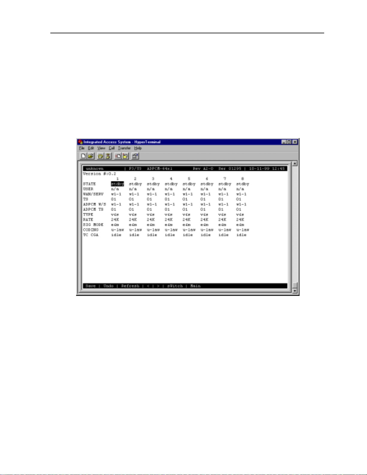
1.3.1 ADPCM Card Main Screen
Y ou must conf igure the ADPCM card ports for ope ration. This is done from th e ADPCM Card
Main Screen, which is shown in Figure 1-1. To go to this screen, highlight the ADPCM card
in the System Main Screen and press <E nter>.
Figure 1-1. Typical ADPCM Card Main Screen
The bottom highlighted line of this screen shows several actions you can perform from the
screen. To perform an action, simply press the key indicated by the uppercase letter of the
desired action. For exa mple, to sav e your config uration sett ings, press “s” to invoke the Save
command. Table 1-2 lists these actions.
Server Cards 1-3
Page 20

Running Head
ADPCM Card User Screens and Settings ADPCM Card
Model No.
Table 1-2. ADPCM Card Main Screen Actions
Action Function
Save Saves changes to settings.
Undo Returns all settings to the last saved state.
Refresh Redraws the current screen with the latest information.
pg_Left Pages through the 64 engines (highest to lowest), 8 at a time.
pg_riGht Pages through the 64 engines (lowest to highest), 8 at a time.
SWitch Switches an active AD PCM car d to its redundant mate.
Main Returns to the ADPCM Card Main Screen. If changes are made to settings
and not saved, users will be prompted to save or lose changes.
Table 1-3 summarizes the ADPCM card configuration parameters and available settings.
These are also described in the following paragraphs.
Table 1-3. ADPCM Card Setting Options and Defaults
Parameter User Options Default
STATE stdby actv rdnt stdby
USER n/a uX-1 through uX-8 n/a
WAN/SERV n/a w1-1 w1-2 w2-1 w2-2 w3-1 w3-2 w4-1 w4-2 none
TS n/a 01-24 01-31 01
ADPCM W/S w 1-1 w1-2 w2-1 w2-2 w3-1 w3-2 w4-1 w4-2 none
ADPCM TS 01-24 01-31 01
TYPE n/a v&s v trnsp v&s
RATE n/a 24K 32K 40K 24K
SIG MODE n/a e&m fxs plar fxo user e&m
CODING n/a u-law a-inv u-law
TC CGA n/a idle busy idle
ST ATE
The State setting determines whether the port is active or inactive. When assigning ADPCM
engine pairs for WAN traffic, set the State setting to stdby (standby) for por ts tha t are no t yet
used or not yet configured. Set it to actv (active) for ports that are ready fo r use.
Setting the State to rdnt (redundant) for any port o n an unu sed card wi ll cause that ca rd to act
as the redundant back-up for all of the other ADPCM cards in that unit. Once a card is
designated as a redundant ADPCM card the only way it can be used for regular ADPCM
traffic is to change the state of the selected port back to either actv or stdby.
When assigning ADPCM engine pairs from use r cards , changing the port from stdby to actv
and saving the selection information on the user card screen will cause the system to
automatically assign an ADPCM engine.
When the engine is assigned from a user card, no changes can be made from the ADPCM card
screen to any of the fields.
1-4 Server Cards
Page 21

ADPCM Card ADPCM Card User Screens and Settings
USER
The User setting identifies the user card and port connected to this engine. This is the place
where the ADPCM card will expect incoming (non-compressed) voice, subrate data, and
B-channel traf fic. If assi gned from a voice, SRU, or BRI card port , this selec tion will show the
user card slot and port n umber (e.g ., u5-2 for th e ca rd in sl ot U5, port 2). If you are as signi ng
a WAN time slot, this setting will s how n/a.
WAN/SERV
The WAN/SERV setting identifies the incoming WAN link connected to this engine. This is
the place where the ADPCM card will expect incoming (non-compressed) voice. If you are
assigning voice traffic to a WAN time slot, this setting will show w1-1 to w4-2. If you are
assigning to a voice card or SRU card port, this setting will show n/a.
TS
The Time slot parameter selects the specific time slot of the above WAN link on which the
ADPCM card can expect incoming voice traffic. If WAN 1-1 is equipped with a T1 CSU
module or a DSX/CEPT module configured for T1 DSX interface, the options are 1 to 24. If
a DSX/CEPT module is installed on that WAN port and that module is configured for CEPT
E1 interface, the options are 1 to 15 and 17 to 31. If you are assigning time slots to voice or
SRU card ports, this setting will be n/a.
ADPCM W/S
The ADPCM W/S setting identifies the out going WAN link to which the engine is connected.
If you are assigning to a voice, SRU, or BRI card port, or to voice traffic from a WAN time
slot, this setting will show w1-1 through w4-2. This is the WAN link to which the ADPCM
card will send its outgoing (compressed) traffic.
ADPCM TS
The ADPCM Ti me slot para meter sel ects the specific tim e slot on the WAN link chosen in the
previous setting that t he ADPCM card will send outgoing compr essed traf fic. The options are
determined by the equipment on the WAN link selected in the previous setting. If WAN 1-1 is
equipped with an 8 12 CSU or 811 DSX/CEPT Module conf igure d for DSX, t he opt ions are 1
to 24. If a DSX/CEP T module is installed a nd configure d for CEPT E1, the opt ions are 1 to 15
and 17 to 31.
Server Cards 1-5
Page 22

Running Head
ADPCM Card User Screens and Settings ADPCM Card
Model No.
TYPE
The Type parameter identi f ies the voice and signaling requir ements for the incoming circui t.
The options are v (voice), voice and v&s (si gnali ng) and trnsp (transparent). Use v when the
input to the ADPCM channel is a 64 kbps channel and inband signaling is not required. Use
v&s when the input to th e ADPCM cha nnel i s a 64 kbps voi ce cha nnel a nd the ADPCM card
must also provide inband signaling.
The trnsp setting allows you to map the outputs of SRU ports to the ADPCM channel. The
subrate data will be cl ocked into the ADPCM channe l at an inpu t rate of 24 kbp s, then pa ssed
transparently (n on-compressed) through t he ADPCM card to the a ppr opr iat e WAN time slot.
This could be useful if you have an odd number of voice channels and want to utilize the
empty engine pair of the last ADPCM channel.
The B-channel traffic from the BRI card also uses the trnsp setting, but it does not place any
restrictions on the compression rates.
If the engine is assigned to a voice card, this selection will sh ow v&s. If assigned to an SRU
card, it will show trnsp. You cannot change it from this screen.
RATE
The Rate parameter identif ies the compression requirem ents for the incoming circuit. T he
options are 24K, 32K, and 40K. The sum of the pair of engines must always equal 64 kbps.
If this engine is assigned to a user card port, the selection will show the value that was chosen
on that port. It cannot be changed from this screen.
SIG MODE
The Signaling Mode parameter identifies the type of signaling required for the incoming
circuit from the network. If v&s was chosen in the Type setting, the options are e&m, fxs,
plar, and fxo. If v or trnsp was chosen in the Type setting, the only option is n/a.
If this engi ne is assigned t o a user card, this selection will show user. It cannot be changed
from this screen.
CODING
The Coding parameter identifies the PCM companding format required for the incoming
circuit from the network. The choices are u-law or a-inv.
If this engine is assigned to a voice or BRI card, this selection will show the value you selected
for that port. If this engine is assigned to an SRU card, this selection will show u-law. It cannot
be changed from this screen.
1-6 Server Cards
Page 23

ADPCM Card ADPCM Card Error Messages
TC CGA
The Trunk Co nditioning CGA settin g identifies t he type of trunk co nditioning requ ired for the
incoming circuit. If v&s is chosen in the Type setti ng, the o ptions are idle or busy. If trnsp or
v is chosen as the Type, the only option is n/a.
If this engine is assigned to a voice card , this se lection will s how the value you selecte d on the
voice card port. If assigned to an SRU or BRI card port, the field will show n/a. It cannot be
changed from this screen.
1.4 ADPCM Card Error Messages
Refer to Appendix B in the System Reference Guide for further information on Error
Messages reg arding this card.
1.5 ADPCM Card Tr oubleshooting
The following are instructions on how to troubleshoot the ADPCM card. This is in case the
card fails for any reason:
1. Green LED on faceplate.
2. Verify that the card is in the right slot, P1 through P3.
3. Reseat the card if necessary. This can be done with the power on.
4. View the card status on the main screen.
5. Check the cards c onf iguration options. Selec t t he card from the main s cre en to do this.
6. Now try to log into the ADPCM main screen. If this still didn ’t work the card may be
bad. Try swapping it with a new card.
7. If the ADPCM card is deter mined to be faulty, replace it and return the faulty unit for
repair to the location specified by your distributor.
Server Cards 1-7
Page 24

Running Head
ADPCM Server Card Specifications ADPCM Card
Model No.
1.6 ADPCM Server Card Specifications
ADPCM Card (887160)
Input Voice Channels Can originate fr om a n y 2- w ire or 4-wire vo ic e c ard or from a DSO o n a
WAN (El/T1 or HDSL) interface. µ-law & A-law 64Kbps PCM
compatible on a per channel basis.
Input Sub-rate Data SRU data traffic at 19.2Kbps or less can be carried on a 24Kbps
sub-channel.
Input BRI traffic B channel voice traffic can be compressed at any of the configurable
rates.
Modem Data Support Transcoder rate: 24, 32 or 40 Kbps; Modem Data: none, up to 4.8Kbps,
V.32 to 9.6Kbps, up to 12Kbps and V.32 bis to 14.4Kbps
Fax Support Transcoder rate for fa x: 24, 32 or 40 Kbps; none, Group II and Group
III fax.
Voice Quality As measured by Mean Opinion Score (MOS) analysis, a subjective
evaluation with a range of 0 (poor quality) to 5 (good quality). Toll
quality voice is accorded a MOS of 4.0 2 4Kb ps tran sco der ra te MO S is
3.6-3.8; 32Kbps transcoder rate MOS is 4.0-4.3 and 40Kbps transcoder
rate MOS is 4.0-4.3
Echo Cancella tion Non provided—typically not required
Signaling Transmitted in-band utilizing CAS transitional signaling, as per ANSI
T1.302—1986 for 32Kbps and modified for use with 24Kbps and
40Kbps. Note Robbed Bit Signaling Alarm Transmission, as specified
in ANSI T1.302a-1989 is not supported.
Maximum Card Count 3 (2 active, 1 redundant)
Transcoder Operatio n Compliant to G.761 Alarm Indication and Fault Handling.
Standards Compatibility
ANSI T1.302 1989
T1.302a 1992
T1.303 1989
CEN EN 500 081-1
EN 500-092-1
EN 60950/A2
ITU-T G.721
G.723
G.726 12/90
1-8 Server Cards
Page 25

FRS Card Introduction
Chapter 2
FRS Card
2.1 Introduction
This chapter provides installation, configuration, and troubleshooting information for the
Frame Relay Server (FRS) (881160) card with the 622xx Firmware.
Note that this card is labeled as an ACS card on its faceplate ejector. It is identified as an FRS
card only in the u ser interf ace screens shown in this chapter. Through out the remai nder of this
chapter, it will be r eferred to as the ACS-FRS card.
2.2 ACS-FRS Card Descriptions
2.2.1 ACS-FRS Card Description (881160)
The ACS-FRS card concentrates mult iple N x 56 K or N x 64K frame relay data stre ams onto
one or more Nx56/64K links of the Integrated Access System. In addition to frame relay
concentration, the card encapsulates data for Nx56/64K HDLC or SDLC data streams. The
frame relay server software runs on the ca rd, which p rovides u p to 68 l ogical po rts. Up to 128
permanent virtual circuits (PVCs) can be configured on a single card. The aggregate speeds
of all ports associated with each FRS cannot exceed 8 Mbps.
The maximum frame size sup ported by the ACS- FRS card is 4, 096 bytes per frame . Each card
can switch 4,000 frames p er second, as suming a fram e size of 64 b ytes per fr ame. Up to thre e
ACS-FRS cards can be used in a system.
2.2.1.1 Card Jumpers/Switch Settings
The ACS-FRS card does not have any jumpers or switches on its motherboard.
2.2.1.2 Installing the Card
Insert the ACS-FRS card into one of the server card chassis slots (P1 to P3) . The system can
accommodate up to three server cards.
Server Cards 2-1
Page 26

Running Head
ACS-FRS Card Descriptions FRS Card
Model No.
2.2.2 ACS-FRS Firmware Features (62220)
The ACS-FRS firmware release 62220 has the same functionality as the firmware release
62218 except for the addition of circuit priorities. The addition of these priorities will assure
that traffic on higher priority circuits will be unaffected by traffic from lower priority circuits.
Four queues will be impl emen ted so no traf fi c of lower priority wil l be al l owed to pass when
there is traffic pending in a higher priority queue.
The overall objective is to pas s lower prior ity IP infor mati on alon g with vo ice tr af fic without
affecting voice quality. The ACS-FRS card will upon congestion favor the higher priority
queues. Lower priority queues will be buffered and transmitted if bandwidth becomes
available before transmit buffers overflow.
The ACS-FRS card will direct frames according to their DLCI (Data Link Connection
Identifier). IP Datagrams can be terminated on a LAN vi a the IPR (IP Router) card.
2-2 Server Cards
Page 27
FRS Card ACS-FRS Card User Screens and Settings
2.3 ACS-FRS Card User Screens and Settings
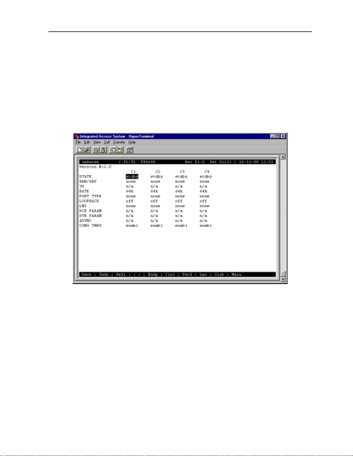
2.3.1 ACS-FRS Card Main Screen
You must configure the ACS-FRS card for operation after insta lling it. This is done in the
ACS-FRS Card Main Screen (Figure 2-1). To go to that screen, highlight the desired
ACS-FRS card in the System Main Screen and press <Enter>.
Figure 2-1.Typical ACS-FRS Card Main Screen (ports C1 to C4)
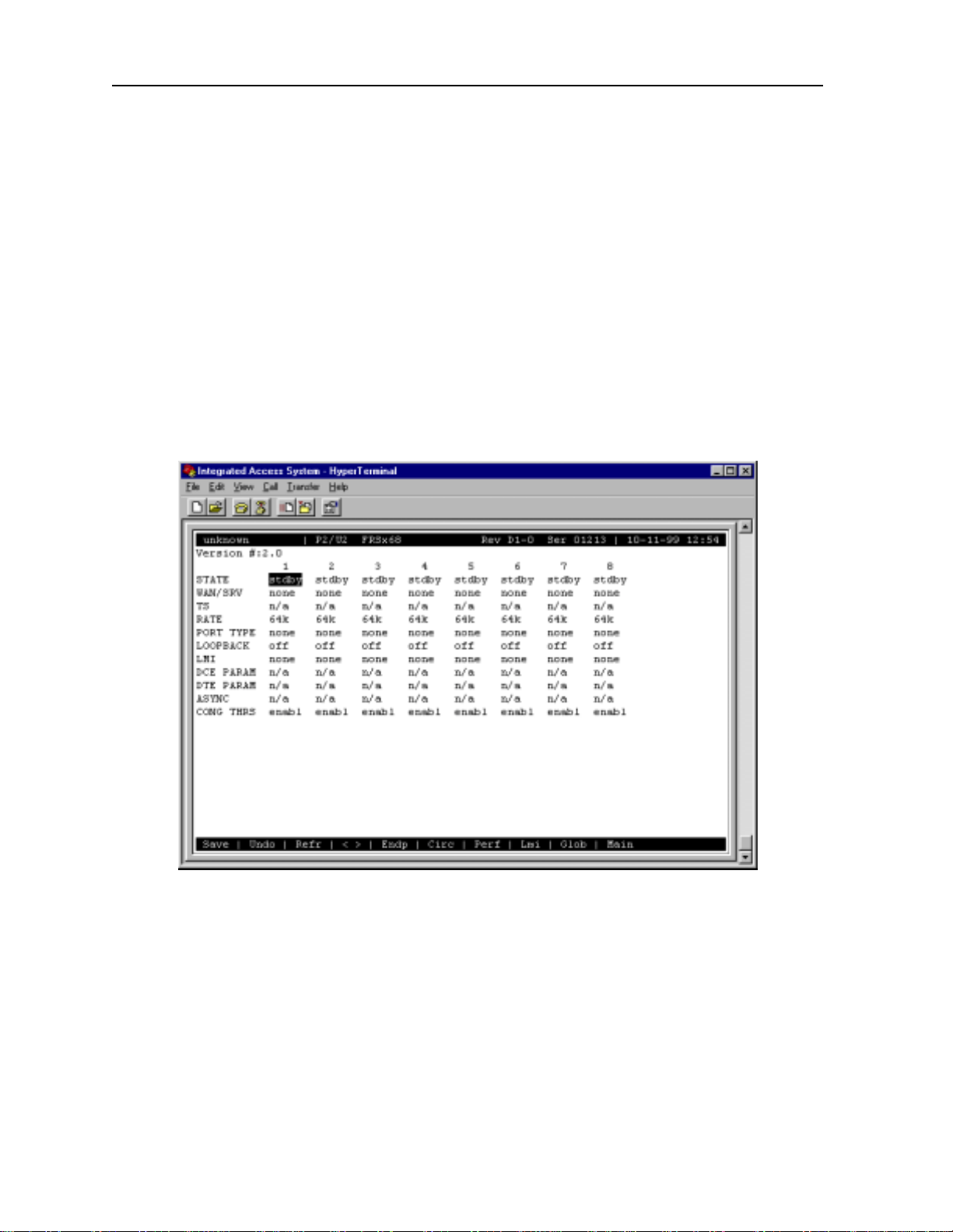
The 68 logical ports of the card a re la beled C1 to C4 and 1 to 64. However, numbere d p orts 1
to 64 do not appear in the abov e display . T o see those por ts, press the "<" and ">" keys to scroll
through them, eight at a time. Figure 2-2 s hows an ACS-FRS card Main Screen display f or the
first eight numbered ports.
The ports C1 to C4 cannot be used for Nx56k, only port 1 to 64 can.
Both the IPR (883060/883160) and the PM-IOR (828060) cards be used with the ACS-FRS
card. The PM-IOR card however, is limited to onl y 14 PVCs per card, whe reas the maxi mum
number of PVCs available on the IPR card is 128.
When connecting the ACS-FRS car d to th e IP R or the PM-IOR, one of the 64 ports avail able
will be used for the communication between the two.
Server Cards 2-3
Page 28
Running Head
ACS-FRS Card User Screens and Settings FRS Card
The maximum bandwidth possible between the IPR and ACS-FRS cards is 62 time slots
provided on the internal buses “A” and “B.”
The “C1” and “C2” ports of the FRS card can not together be assigned mo re than 32 time sl ots
due to hardware limi ta ti ons . The same is true for t he FRS ports “C3” and “C4”. A total of 6 4
time slots can be assigned all the “C” ports. A similar limitation exists for the ports 1-64
terminating the voice circuits. Each group of 32 ports, 1-32, and 32-64 share a common
internal pipe limited to 32 ti me slots each. The maximum number of time slots allows per port
is one when all ports per group is acti ve. If half th e number of ports of a group i s active, t wice
the number of time slots can be assigned per port.
The maximum internal bandwidth between FRS cards and HSU cards of an Integrated Access
System is limited by the pools size of 126, but also limited by usage from this pool by the
IPR/FRS connections and possible voice card usage.
Model No.
Figure 2-2.Typical ACS-FRS Card Main Screen (numbered ports)
Table 2-1 lists the actions you can perform from the ACS-FRS Card Main Screen. These
actions are li sted at the bott om line of the sc reen; they are pe rformed by pressin g the uppercase
letter key. For example, to save your opti on settings, press “s” to invoke the Save command.
Table 2-2 summarizes the parameters and their option settings and defaults.
2-4 Server Cards
Page 29

FRS Card ACS-FRS Card User Screens and Settings
Table 2-1. ACS-FRS Card Main Screen Actions
Action Function
Save Saves change s to settings.
Undo Returns all settings to the last saved state.
Refresh Redraws the screen.
< and > Lets you scroll through the 68 logical ports assignable on each ACS-FRS
Endp Brings up the PVC Endpoints Screen where endpoints for each PVC are
Circ Brings up the Circuits Screen where alternate endpoints and endpoint
Perf Initiates Port Performance Monitoring of the selected AC S-FRS card port.
Lmi Brings up the LMI Screen where additional performance statistics are
Glob Brings up the Global Screen that identifies the ACS-FRS card by IP number
Main Returns to the System Main Screen. If changes are made to settings and not
card.
assigned. See the PVC Endpoints Screen section of this chapter.
switching are assigned. See the Circuits section of this chapter.
Refer to Port Performance Data section of this chapter.
stored. See the LMI section of this chapter.
and netmask. See the Global Setup section of this chapter.
saved, you will be prompted to save or lose changes.
Table 2-2. ACS-FRS Card Main Screen Option Settings and Defaults
Parameter User Options Notes Default
STATE stdby actv stdby
WAN/SRV none w1-1 w1-2 w2-1 w2-2 w3-1
w3-2 w4-1 w4-2
TS n/a table n/a
RATE 64k 64
PORT TYPE none u-dce nni u-dte frad none
LOOPBACK off line local off
LMI none ansi ccitt lmi 1 none
DCE PARAM n/a enabl 2 n/a
DTE PARAM n/a enabl 3 n/a
ASYNC no yes no
CONG THRS enabl 1%-100% 4 enabl (95%)
Notes:
1. ansi, ccitt, and lmi can only be selected when Port Type is changed to any selection
other than none.
2. When Port T ype is u-dce or nni, this parameter will let you change the Er ror Threshold,
Poll Verify Timer, and Events Counter settings.
none
3. When Port Type is u-dte or nni, this parameter will let you change the Error Threshold,
Poll Interv al Timer, Events Counter, and Full Status Frequency.
4. Press <Enter> to select the desired Congestion Threshold percentages.
5. If connected to a user port, this displays user slot number and port (e.g. U1-2).
Server Cards 2-5
Page 30

Running Head
ACS-FRS Card User Screens and Settings FRS Card
Model No.
STATE
The State setting determines whether the port is active or inactive. Set the State field to stdby
(standby) for ports you are not using or h ave not ye t configured. Or, set it to actv (active) for
ports that are ready for use.
WAN/SRV
The WAN setting identifies the WAN link assigned to this port. You do not have to assign a ll
ports on the same card to the same WAN link. You also don’t have to assign card ports to
contiguous time slots of a WAN link. The default value is none.
TS
The Time Slot setting identifies the time slots on the WAN link when wan is selected in the
previous setting. The ACS-FRS card can use many (up to 24 T1 or 31 E1) time slots on a
single WAN port, in order to create a sup er-rate circ uit f or an i ndi vidual FRS port. One or a ll
time slots of a T1 or E1 link can b e assemb led for us e by the FRS p ort, accor ding to t he speed
requirements of the DTE.
You can assign time slots by pressing <Enter> and using the space bar to select and deselect
the required number of time slots. These assignments do not have to be contiguous.
RATE
The Rate setting allows you to adjust the speed of the circuit according to the application
requirements. The onl y s pee d a vailable for ports C1to C4 is 64k (64 kbps). However, ports 1
to 64 can be set to either 56k or 64k.
PORT TYPE
The Port Type identifies the type of interface expected for this port. The selections are none,
u-dce (User-to Network Interface), nni (Network to Network Interface), u-dte (User-to
Terminal Equipment), and frad (Frame Relay Assembler/Dissembler).
LMI
The Local Management Interface setting allows you to select the protocol to be used by this
port. The options are none, ansi (ANSI T1.617 Annex D), ccitt (ITU Q.933 Annex A), and
lmi (Group of Four specification).
2-6 Server Cards
Page 31

FRS Card ACS-FRS Card User Screens and Settings
DCE PARAM
The DCE Parameters setting will show n/a unless a Port T ype of u-dce or nni is selected. Once
set to enable, the user may choose from the following options:
• Error Threshold (N392)
• Poll Verify Timer (T391)
• Events Counter (N393)
The Error Threshold (N392) coun ts the error s that will be tole rated durin g the cast numb er of
events as set by the Events Counter before declaring the LMI link down. The number of errors
options are 1 to 10. The value i s input usin g the k eyboard of th e cont rol t erminal . The de fault
is 3.
The Poll Verify Timer (T391) allows you to select the time interval (in seconds) that should
elapse between “keep alive” messages sent from the corresponding DTE. The number of
seconds options are 5 to 30. The default is 15 seconds.
The Events Counter (N393) allows you to select the window size for the number of events
(frames) in which errors will be counted. If error threshold (N392) is exceeded within cast
N393 frames, the link is declared down. The number of events counted are 1 to 10. The def ault
is 4.
DTE PARAM
The DTE Parameters setting will sho w n/a unless a Port T ype of u-dte or nni is selected. Once
set to enable, the user may choose from the following options:
• Error Threshold (N392)
• Poll Interval Timer (T391)
• Events Counter (N393)
• Full Status Frequency (N391)
The Error Threshold (N392) coun ts the error s that will be tole rated durin g the cast numb er of
events as set by the Events Counter before declaring the LMI link down. The number of errors
options are 1 to 10. The value i s input usin g the k eyboard of th e cont rol t erminal . The de fault
is 3.
The Poll Verify Timer (T391) allows you to select the time interval (in seconds) that should
elapse between “keep alive” messages sent from the corresponding DCE. The number of
seconds options are 5 to 30. The default is 15 seconds.
Server Cards 2-7
Page 32

Running Head
ACS-FRS Card User Screens and Settings FRS Card
The Events Counter (N393) allows you to select the window size for the number of events
(frames) in which errors will be counted. If error threshold (N392) is exceeded within cast
N393 frames, the link is declared down. The number of events counted are 1 to 10. The def ault
is 4.
The Full Status Frequency (N391) allows you to select the number of “keep alive” messages
(see T391 above) that s hould elapse before t he full status i nquiry message is se nt. The number
of messages are 1 to 255. The default is 6.
Model No.
ASYNC
This setting specifies whether a synchronous state's update messages are to be sent when
changes on the link occur. If set to no, link updates are sent at regular intervals, in response to
Full Status Requests.
CONG THRS
The Congestion Thresh old allows you to select the amoun t (in percenta ge) that the i nternal Tx
queues on the port must be filled before declaring this port is congested (this information is
communicated by FECN and BECN flags). The options are 1 to 100.The defaul t is 95.
Since DE (Discard-Eligibility) frames are not queued to the same extent as non-DE frames,
DE-frames may be dropped when mixed with non-DE frames on the same port before
congestion control is initiated.
T o assure congestion cont ro l is initiated even for DE-fr ames u nder the cond it ions mentioned
above, the TX threshold value must be reduced sufficiently to match the percentage
DE-frames being buffered.
2-8 Server Cards
Page 33

FRS Card ACS-FRS Card User Screens and Settings
2.3.2 Frame Relay Endpoints Screen
You can have up to four frame relay endpoints (two for the actual endpoints of the PVC and
two that can act as backup should the primary link fail). All frame relay endpoints are
inventoried on the Frame Relay Endpoints Screen, and all endpoints must be defined from this
screen before the user can provision the circuit.
Figure 2-3 shows a typical Frame Relay Endpoints Screen, which can be viewed by pressing
“e” (Endp) in the ACS-FRS Card Main Screen. Table 2-3 lists the actions you can perform
from the bottom line of this screen.
Figure 2-3.Typical Frame Relay Endpoints Screen
In Figure 2-3 above illustrates the frame relay endpoint screen for two voice circuits
terminated on port 01, and 02 transported over port “C1” via the HSU to the remote device.
Figure 2-3 also sho ws the th ree IP endpo ints defined on C1 towards the remote d evice, and on
C2 towards the IPR.
Server Cards 2-9
Page 34

Running Head
ACS-FRS Card User Screens and Settings FRS Card
Model No.
Table 2-3. Frame Relay Endpoints Screen Actions
Action Function
Refresh Redraws the screen.
New Adds new circuit endpoints for each of the Frame Relay ports
dElete Deletes the highlighted endpo int s. The sy stem requires confirmation with a
pgUp Pages through the pages of Frame Relay endpoints from newest to oldest.
pgDn Pages through the pages of Frame Relay endpoints from oldest to newest.
Main Returns to the System Main Screen. If changes are made to settings and not
yes/no question before deleting the circuit.
saved, you will be prompted to save or lose changes.
NAME
The Name setting allows you to identify each of the endpoints with a discrete name. This
setting is case-sensitive, so a endpoint called “P101” is not the same as one called “p101.”
Circuits are built using these names.
PORT
The Port number identif ies the Frame Relay po rt used for this cir cuit. This informat ion is input
by the user from the keyboard. Valid entries are C1 to C4 and 1 to 64.
DLCI
The Data Link Connection Identifier is a unique number assigned by the carrier to this
endpoint. The number must be between 1 and 996 (ansi or ccitt), or 1 and 1007 (lmi). The oth er
numbers within the 1023 range are reserved.
BC(Kb)
The Bits Committed setting defines the threshold for the transmit rate (outgoing frames)
where the card will make every effort to deliver the traffic to the subscriber . The time used to
average rate is determined by the card by dividing the Committed Information Rate (CIR) by
Bc. The number input must be between 0 and 2048.
BE(Kb)
The Bits Excessive set ting define s the threshol d for the tra nsmit rate (ou tgoing fr ames) where
the carrier will admit the frames into the network (in effect, this is the maximum transmission
rate). Frames sent below this threshold but above the BC (KB) threshold are admitted into the
carrier network with the DE (discard eligibility) bit set. If congestion occurs in the network,
these frames are the first to be discarded. The options are 0 to 2048.
2-10 Server Cards
Page 35

FRS Card ACS-FRS Card User Screens and Settings
CIR (Kbps)
The Committed Information Rate (in kbps) is the actual information rate contracted with the
carrier. The options are 0 to 2048. CIR/Bc is used to calculate average data rate.
When CIR is set to 0, all frames forwarded will ha ve the DE-bit set.
ALLOW RED
When Allow Red is set to yes transmit rate exceeding BC+Be will be forwarded if there is
capacity available. When set to no forwarding will not be attempted.
PRI
The Priority field allows selection of p riority 1-4. This field is only a vailable for the ACS-FRS
(881163) card. Default setting is priority “4”. When the user has installed ACS-FRS (8811)
card the priority field will not be able to be edited and will show n/a.
Server Cards 2-11
Page 36

Running Head
ACS-FRS Card User Screens and Settings FRS Card
Model No.
2.3.3 FRS Circuits Screen
The FRS Circuits Screen allows you to identify PVC endpoints and alternate PVCs to serve
as backups to the original endpoints if the main link fails. Endpoints must be inventoried on
the PVC Endpoints Screen before they can be used to set up backup ci rcuits. Figure 2-4
shows a typical Circ uits Scre en, and Figur e 2-5 is a n endpoint circuit example. Table 2-4 lists
the actions you can perform from the bottom of this screen.
Figure 2-4.Typical Circuits Screen
Currently the FRS is limited t o 128 circuit s connecting 256 endpoints. The Integrate d Access
System is required to serve a maximum of 8 EBTS units, each having a total of 16 channels.
Each EBTS can be address by three different IP addresses. Each IP address represents a
specific type of servic e. Each of the ser vices: si gnaling, mess ing, and NMS will be addressed
EBTS by a different IP address. The IP router card will encapsulate IP Datagrams for each
service wi th a unique DLC I value. The IP frames are self-contained in th at channel
information is embedded in the data of the datagram.
The total of 152 circuits will be required for both voice and IP circuits. Even though the
maximum number of circuits for a single FRS card could be expanded to accommodate the
needed number . When using two FRS cards, 64 ci rcuits per car d can be used as IP c ircuits after
64 circuits have been used as voice circuits.
2-12 Server Cards
Page 37

FRS Card ACS-FRS Card User Screens and Settings
Table 2-4. FRS Circuits Screen Actions
Action Function
Refresh Redraws the screen.
New Creates new circuit.
dEl Deletes the highlighted circuit. You will be prompted with a yes/no question
pgUp Pages up through the circuits.
pgDn Pages down through the circuits.
Perf Brings up circuit performance data for the highlighted circuit. See the
Status Shows circuit status, as described above.
swA Used for manually switching from primary en dpoi nt A to alternat e endpoin t
swB Used for manually switching from pri mary endp oint B t o altern ate endpoi nt
Main Returns to the FRS Card Main Screen. If changes are made to settings and
prior to actual deletion of the circuits.
Circuit Performance Data section of this chapter.
A, and back.
B, and back.
not saved, you will be prompted to save or lose changes.
End Points
RI
B
U
HS
5
3
0/
53
S 60
O
X
F
9
813
CPU
K
C
O
CL
NVRAM
WAN
F
I
S1
D
T1+
P
1
N
O
D
E
T
P
E
2
R
M
C
O
M
P
P
3
W1-1
U
CS
2
1W
P
4
DSX
IAD #1
T
U
HS
35
/
30
5
60
S
T
U
S
H
5
3
0/
3
5
60
S
T
SU
H
530/35
60
S
T
U
S
H
5
3
/
0
53
S 60
T
U
S
H
530/35
0
6
S
HSU-T
35
/
530
S 60
P
1
.
c
In
s,
n
Premisys Communicatio
Model IMACS/600
5A
T
V
50
2
C
E
I
®
se
u
F
3
6
A SB
5
70
7
R
~
L
V
50
2
C
d
120-200-240V
SA
-
C
ue
/
L
in
U
O
Hz
+
nt
o
-
r c
+
o
M
F
-
3A, 50 / 60
V
B
+
R
P
V
ire,
A
f
st
G
CAUTION:
V
ain
e
g
N
sam
1
ion a
t
R
e
h
ec
t
t
h
ro
it
p
y w
l
n
se
u
f
ace o
f
pl
o
5A
g
re
in
U
rat
d
V
n
L
e a
e
c
24/48
yp
®
t
r Sour
we
o
P
9
K0
9
lass 2
C
STED
I
L
e
elephon
T
ent
pm
qui
E
Frame Relay
Network
NY Prm
NY Alt
T
US
H
0/35
3
5
0
6
S
HSU-T
35
0/
3
5
S 60
RI
B
U
S
H
30/35
5
0
6
S
FXO
9
13
8
U
P
C
CLOCK
M
A
R
V
N
N
A
W
F
I
1
+DS
T1
P
1
P
1
N
O
D
E
T
P
E
2
R
M
C
O
P
M
P
1
P
3
1
1W
CSU
1-2
W
P
4
DSX
IAD #2
LA Prm
T
U
HS
5
3
/
0
53
60
S
T
U
S
H
35
/
30
5
60
S
T
HSU
35
0/
3
5
60
S
T
U
S
H
5
3
0/
53
60
S
00
6
Premisys Communications, Inc.
Model IMACS/
A
5
T
V
50
2
IEC
®
e
Fus
SB
63
0
5A
77
V
R
~
L
40
V
2
0
25
002
C
120
ed
-
CSA
L/
z
inu
U
O
H
+
t
n
60
-
/
+
50
,
M
For co
-
:
3A
V
B
+
,
R
V
A
G
CAUTION
V
ainst fire
e
g
N
a
n
sam
io
R
ect
t
h the
o
r
it
p
nly w
e o
lac
ep
r
ing of fuse
t
U
ra
d
an
L
e
c
pe
24/48V 5A
y
®
ur
t
o
S
9
s 2 Power
s
9K0
a
l
C
TED
IS
L
one
h
ep
el
T
ent
m
p
i
u
q
E
LA Alt
Router
Figure 2-5.Typical FRS Endpoint Circuit
ST ATE
The State setting sho ws the st at us of the circuit. The options are stdby and actv. This setting
shows the administra tive s tate of the c ircui t. The op er ationa l sta te of e ach of t he endpo int s of
the circuit is shown in the STATUS column.
ENDP A
Endpoint A is the FRS port use d to provide service to t he p ri ma ry end of t he PVC. All of the
endpoint names assigned on the PVC Endpoints Screen (discussed earlier) are eligible
options.
Server Cards 2-13
Page 38

Running Head
ACS-FRS Card User Screens and Settings FRS Card
Model No.
ENDP B
Endpoint B is the FRS port used to provide service to the secondary end of the PVC. All of
the endpoint names assigned on the PVC Endpoints Screen (discussed earlier) are eligible
options.
ALT A
Alternate Endpoint A i s the FRS port used to provi de backup ser vice to the p rimary end of the
PVC. All of the endpo int names assigned on the PVC Endpoint s Screen (disc ussed earlier) are
eligible options.
ALT B
Alternate Endpoint B is t he FRS port used to provide back up se rv ice to the secondary end o f
the PVC. All of the endpoint names assigned on the Endpoint screen (discussed earlier) are
eligible options.
SWCH A
The Switch A setting ident ifies the metho d used to switch from the primar y Endpoint A to th e
Alternate Endpoint A. The o pti ons are manual and w/to (with time-out). If w/to is chosen, a
second set ting appears for the user to select the time-out period (in minutes) from 1 to 60.
In the event of a failure of the primary endpoint, a setting of manual allows the user to
manually switch from primary to the alternate endpoint. When the primary endpoint is
restored, the user must manually switch it back again.
In the event of a failure of the primary endpoint, a setting of w/to will automatically switch
the PVC from primary to alternate. When the primary endpoint is restored, the system will
automatically switch it back again after the predetermined time set by the user.
SWCH B
The Switch B setting identifie s the met hod used t o switch from the primary Endpoi nt B to the
Alternate Endpoint B. The options are manual (pressing “b” from the bottom line of the
screen), and w/to (with time-out). If w/to is chosen, a second setting appears for the user to
select the time-out period (in minutes) from 1 to 60.
In the event of a failure of the primary endpoint, a setting of manual allows the user to
manually switch from primary to the alternate endpoint if he chooses. When the primary
endpoint is restored, the user must manually switch it back again.
2-14 Server Cards
Page 39

FRS Card ACS-FRS Card User Screens and Settings
In the even t of a failure of the primary endpoint, a setting of w/to will automa tically switch
the PVC from primary to alternate. When the primary endpoint is restored, the system will
automatically switch it back again after the predetermined time set by the user.
STATUS
The Status column sh ows the status of th e Primary and Alterna te endpoints and the con nection
of the PVC. Y ou ca nnot edit this field . The values are “A” (Primary A is active), “B” (Primary
B is active), “U” (the connect ion is up), “a” (Alternate A is active), “b” (Alternate B is acti ve)
and “D” (connection is down). Only displays status when “S” (Status) is selected from the
bottom of th e screen.
Server Cards 2-15
Page 40

Running Head
ACS-FRS Card User Screens and Settings FRS Card
Model No.
2.3.4 FRS Circuit Performance Data Screen
The ACS-FRS card accumu lates statistics that show performance characteristics of each
circuit. To access the FRS Circuit Performance Data Screen, highlight one of the circuits on
the FRS Circuits Screen and press “p” (Perf). Figure 2-6 shows a typical FRS Circuit
Performance Data Screen, and T able 2-5 lists the act ions you can perfo rm from its bottom lin e.
The circuit performance data is kept in 15-minute (900 seconds) time increments for a total of
96 periods (24 hours). Each screen shows the current 15 minute segment and the past 12
periods with totals at the bottom of the column. Press “d” to page backward through the
previous 96 periods, or “u” to page forward through these periods. After each period, the
oldest 15-minute segment (from exactly 24 hours ago) is discarded. Since information is not
updated on screen in real time, you must pres s “r” (Refresh) periodically to obtain up-t o-date
statistics for the current period.
Figure 2-6.Typical Circuit Performance Data Screen
2-16 Server Cards
Page 41

FRS Card ACS-FRS Card User Screens and Settings
Table 2-5. Circuit Performance Data Screen Actions
Action Function
Refresh Since performance statistics are not updated on screen in “real” time, the
Clear Clears all performance statistics for the highlighted port.
PgUp Pages up through the 96 time segments.
PgDn Pages down through the 96 time segments.
ConG Brings up the Circuit Congestion Data Screen. See the Circuit Congestion
Main Returns to the Circuits Screen.
AB FRAMES
The AB FRAMES counter shows the total number of f rames sent from endpoint A to end point
B.
BA FRAMES
refresh key must be pressed to obtain updated performance figures.
Data section of this chapter.
The BA FRAMES counter shows the total number of frames sent fro m endpoint B to e ndpoint
A during the time period.
AB BYTES
The AB BYTES counter sh ows the tot al numbe r of bytes sent fro m endpoi nt A t o endp oint B
during the time period.
BA BYTES
The BA BYTES counter sh ows the tot al numbe r of bytes sent fro m endpoi nt B t o endp oint A
during the time period.
AB DRP
The AB DRP counter shows the total number of frames dropped that were sent from end point
A to endpoint B during the time period.
BA DRP
The BA DRP counter shows the total number of frames dropped that were sent from end point
B to endpoint A during the time period.
Server Cards 2-17
Page 42

Running Head
ACS-FRS Card User Screens and Settings FRS Card
Model No.
STATUS
The Status column shows the status of the selected circuit during the 15-minute intervals. The
Status values are A or a (capital A means endpoint A was switched from al tern ate to pr imary
and lower-case a means the endpoint A was switched from primary to alternate); B or b
(capital B means endpoint B was switched from alternate to primary, lower-case b means
endpoint B was switched from primary to alternate); D (connection was down during that
period); and S (circuit was placed in standby state during that period).
2-18 Server Cards
Page 43

FRS Card ACS-FRS Card User Screens and Settings
2.3.5 Circuit Congestion Data Screen
The ACS-FRS card al so accumulat es stati stics t hat show you the conge stion char acteristics of
each of the circuits. To access the Circuit Congestion Data Screen, press “g” (conG) in the
FRS Circuit Performance Data Screen. Figure 2-7 shows a typical Circuit Congestion Data
Screen, and Table 2-6 lists the actions you can perform from its bottom line.
The data on this screen is kept in 15-minute (900 seconds) time increments for a total of 96
periods (24 hours). Each screen shows the current 15 minute segment and the twelve past
periods with totals at the bottom of the column. Press “d” (pgDn) to scroll backward through
the previous 96 periods, or “u” (pgUp) to scroll forward through these periods. After each
period, the oldest 15-minute segment (from exactly 24 hours ago) is discarded. Since
information is not updated on screen in real time, you must press “r” (Refresh) periodically
to obtain up-to-date statistics for the current period.
Figure 2-7. Typical Circuit Congestion Data Screen
Server Cards 2-19
Page 44

Running Head
ACS-FRS Card User Screens and Settings FRS Card
Model No.
Table 2-6. Circuit Congestion Data Screen Actions
Action Function
Refresh Since performance statistics are not updated on screen, you must press “r”
pgUp Pages up through the 96 time segments.
pgDn Pages down through the 96 time segments.
A->b Selects the direction of the congestion data.
B->a Selects the direction of the congestion data.
Main Returns to the Circuit Performance Data Screen.
to obtain updated performance figures.
GREEN FR
The Green Frames count er shows the tota l number of frames se nt on the circu it that fell within
the Committed Information rate contracted with the carrier during the time period.
DROP
The first DROP shows t he number of Green F rames t hat were dr opped by the card duri ng the
time period.
YEL FR
This counter shows the to tal number of frames on the circ uit that exceeded the Bc rate but were
within the Be rate assigned to the endpoin t during the time period.
DROP
The second DROP shows the n umber of Yellow Frames that were dropped by t he card dur ing
the time period.
RED FR
This counter shows the total number of frames on the circuit that exceeded the Be rate
assigned to the endpoint during the time period.
DROP
The third DROP shows the number of Red Frames that were dropped by the card during the
time period.
2-20 Server Cards
Page 45

FRS Card ACS-FRS Card User Screens and Settings
FECN
The Forward Error Co ngestion Notific ation counter l ogs the number of frames with the FECN
bit set by the system. This flag tells you that congestion avoidance procedures should be
initiated.
BECN
The Backward Error Congestion Notification counter logs the number of frames with the
BECN bit set by the syste m. This flag tells you that con g es ti on a voi dance procedures should
be initiated.
Server Cards 2-21
Page 46

Running Head
ACS-FRS Card User Screens and Settings FRS Card
Model No.
2.3.6 Port Performance Data Screen
The ACS-FRS card also accumulates stat istics tha t show you the perfor mance character istics
of each active port. T o a ddress the Port Performance Dat a Screen, highlight one of the 68 ports
on the ACS-FRS Card Main Screen and press “p” (Perf). This will access t he Port
Performance Data Screen associated with the selected port. Figure 2-8 shows a typical Port
Performance Data Screen, and T able 2-7 lists the act ions you can perfo rm from its bottom lin e.
The data on this screen is k ept by 15-minute (900 seconds) time increments for a total of 96
periods (24 hours ). Each scree n shows th e curr ent 15 minute se gment a nd the past 12 peri ods
with totals at the bottom of the column. Press “d” (pgDn) to page backward through the
previous 96 periods, or “u” (pgUp) to page forward t hrough the se periods . After eac h period,
the oldest 15-minute segment (from exactly 24 hours ago) is discarded. Since information is
not updated on screen in real time, you must press “r” (Refresh) periodically to obtain
up-to-date statistics for the current period.
Figure 2-8. Typical Port Performance Data Screen
2-22 Server Cards
Page 47

FRS Card ACS-FRS Card User Screens and Settings
Table 2-7. Port Performance Data Screen Actions
Action Function
Refresh Since performance statistics are not updated on screen in “real” time, the
Clear Clears all performance data for the highlighted port.
pgUp Scrolls up through the 96 time segments.
pgDn Scrolls down through the 96 time segments.
Main Returns to the System Main Screen.
PORT
The Port setting shows the port number associated with the performance statistics on this
screen. This was t he p ort highlighted on the M ai n s cr een when the “P” key was pressed. The
FRS card has a maximum of 68 ports.
FRAME Rx
refresh key must be pressed to obtain updated performance figures.
The Frame R eceived column tabulates th e total number of frames recei ved during the 15
minute period.
FRAME Tx
The Frame T ransmitted col umn tabulates the total number of frames tran smitted duri ng the 15
minute period.
OCTETS Rx
The Octets Received column tabulates the total number of bytes received during the 15 minute
period.
OCTETS Tx
The Octets T r ans m it te d column tabulates the t ot al number of bytes transmitte d du ri ng the 15
minute period.
DRPRx
The Dropped (frame) Received column tabulat es t he total number of fr ames dr opped on port
while being received.
Server Cards 2-23
Page 48

Running Head
ACS-FRS Card User Screens and Settings FRS Card
Model No.
DRPTx
The Dropped (frame) Transmitted column tabulates the total number of frames dropped before
being transmitted during the 15 minute period.
STATUS
The Status colu mn shows diffe rent status cond itions of the por t during each 15-mi nute period.
The status codes are listed at the bottom of the screen. The status codes are T (DTE down), C
(DCE down), L (loopback), and S (standby).
2.3.7 LMI Data Screen
Local Management Interface information is displayed on the LMI Data Screen. To access this
screen, press “L” in the ACS-FRS Card Main Screen to invoke the Lmi command. Figure 2-9
shows a typical LMI Data Screen, and Table 2-8 lists the actions you can perform from the
bottom line of this screen.
Figure 2-9.Typical LMI Data Screen
2-24 Server Cards
Page 49

FRS Card ACS-FRS Card User Screens and Settings
Table 2-8. LMI Data Screen Actions
Action Function
Refresh Saves changes to settings.
Clear Re turns all settings to the last saved state.
Main Returns to the System Main Screen.
STATUS INQ. RX
The Status Inq uiry Received figure shows the total n umber of st atus inquir y requests r eceived
by the DCE.
STATUS TX
The Status T r ansmitted figure s hows the to tal nu mber of “keep alive” and full status inqu iries
sent by the DCE.
ASYNC STATUS TX
If the ASYNC parameter in the ACS-FRS card Main Screen is set to yes for the port,
asynchronous status packets transmitted by the DCE are tabulated in this figure.
SEQ # MISMATCH
The Sequence Number Mismatch figure shows the total number of sequence number errors
have been received by the DCE.
TIMEOUTS
The Timeouts fi gure shows the total numbe r of times that expected requests from the DTE are
missed.
BAD HDLC FRAMES
The Bad HDLC Frames figure shows the total number of HDLC errors received on this port.
INVALID FRAMES
The Invalid Frames figure shows the total number of short frames or frames with invalid FR
headers received on this port.
Server Cards 2-25
Page 50

Running Head
ACS-FRS Card User Screens and Settings FRS Card
Model No.
NO ROUTE FRAMES
The No Route Frames f igure shows the total number of fr ames rec eived t hat have incorr ect or
unknown DLCI for this port.
STATUS INQ. TX
The Status Inquiry Transmit figure shows the total number of status inquiry requests
transmitted by the DTE.
STATUS RX
The Status Received figure shows the total number of “keep alive” and full status inquiries
received by the DTE.
ASYNC STATUS RX
If the ASYNC parameter in the ACS-FRS card Main Screen is set to yes for the port,
asynchronous status packets received by the DTE are tabulated in this figure.
SEQ # MISMATCH
The Sequence Number Mismatch figure shows the total number of sequence number errors
have been received by the DTE.
TIMEOUTS
The Timeouts fi gure shows the total numbe r of times that expected requests from the DTE are
missed.
2-26 Server Cards
Page 51

FRS Card ACS-FRS Card User Screens and Settings
2.3.8 Global Setup Screen
The Global Data Screen allows you to identify the frame relay server by its IP address. To
access this screen, pr ess “g” in the ACS-FRS Card Main Screen to invoke the Glob command.
Figure 2-10 shows the Global Data Screen, and Table 2-9 lists the available actions from the
bottom line of this screen.
Figure 2-10. Global Data Screen
Table 2-9. Global Data Screen Actions
Action Function
Save Saves change s to settings.
Undo Returns all settings to the last saved state.
Refresh Redraws the screen.
Main Returns to the System Main Screen. If changes are made to settings and not
saved, you will be prompted to save or lose changes.
IP ADDRESS
Enter the IP address for the frame relay server in this field.
Server Cards 2-27
Page 52

Running Head
ACS-FRS Card User Screens and Settings FRS Card
NETMASK
Enter the Netmask address in this field. This is the Netmask for the Integrated Access System.
This address is also assigned on the Interface card’s IP Screen.
Model No.
2-28 Server Cards
Page 53

FRS Card ACS-FRS Card Error Messages
2.4 ACS-FRS Card Error Messages
Refer to Appendix B in the System Reference Guide for further information on Error
Messages reg arding this card.
2.5 ACS-FRS Card Troubleshooting
Problems with a FRS card could indicate a number of causes. Some possibilities are:
• T1 or E1 network failure
• Improper frame relay network configuration
• Improper FRS card configuration
• Improper user card configuration
• Faulty cabling between the DTE and user card
• Improper DTE configuration
T ypically, a problem is indicated by the inabil ity to send or receive fr ame relay traf fic th rough
the FRS card. There are numerous ways of isolating and clearing the problem. When
troubleshooting frame relay communications problems through an FRS card, follow this
general sequence:
1. If all Frame Relay traf fic is af fected, verify that the US/EUR jumper is corre ctly placed
to match the US/EUR jumper on the chassis. The FRS card performs a self-test on
power-up. A “healthy” card will have a green LED lit on the front panel. Do not
proceed with further steps until a green LED is present.
2. V eri fy that the T1 or E1 network is working properly by checking f or current CGA-Red
and CGA-Yell ow alar ms (see Cha pter 3 -A for a larm vie wing ins truct ions) . If no CGA
alarms are present that would affect the frame relay traffic, continue with step 3.
3. V er ify that the FRS port is connected to the prope r WAN card and time slot or user card
port and that the correct type of LMI is selected. If a user card port is used, verify the
configuration settings on the user card port and the cable connection to the DTE. The
LMI must be UP for data to flow on the circ uit. Do not pr oceed with fur ther step s until
the LMI is up.
4. Go to the Port Performance Monitoring Screen by pressing P from the FRS Main
Screen. Analyze the regi ster and status information provided to help determine the
cause of the problem.
Server Cards 2-29
Page 54

Running Head
ACS-FRS Card Troubleshooting FRS Card
5. Go to the Circuits Screen of the FRS card (which can be accessed by selecting Circ
from the FRS Main Screen). Verify that the affected circuit STATUS is up (indicated
by a “U”). If it is not up, this may indicate that an LMI is down in the far end of the
circuit. Highlight the affected circuit and type P and the performance registers for the
circuit will appear . Anal yze the information p rovided to help deter mine the cause of t he
problem.
6. Loopbacks are availabl e on the “C” ports only . If a “C” port wit h an LMI is looped back
toward itself, the PORT TYPE must be nni for the loopback to function.
7. If the FRS card is determined to be faulty, replace it and return the faulty unit for repair
to the location specified by your distributor.
Model No.
2-30 Server Cards
Page 55

FRS Card ACS-FRS Server Card Specifications
2.6 ACS-FRS Server Card Specifications
ACS-FRS Card (Model 88 1160)
Input/Output Ports 68 logical ports (maximum)
Input Traffic Ports T1, E1, fT1, fE1, V.35, RS422, EIA530, OCU-DP, FRAD
Output Traffic ports T1, E1, fT1, fE1, V.35, RS422, EIA530
Output Port types UNI DCE, UNI DTE, NNI, Nx64K/56K FRAD
Max Frame Size 4K Bytes
Traffic Bandwidth 8 Mbps Full Duplex
Performance 4,000 Frames per second (maximum)
Number of PVCs 128
System Capacity Maximum 3 per System
Management RFC1315 DTE MIB, Frame Relay Service MIB, SNMP Alarm Traps
per RFC 1215
Connectivity SNMP or TELNET
LMI Options Q.933 Annex A, ANSI T1.617 Annex D, LMI (Gang of 4), None
Information Rates CIR = 0 to 2048 Kb/s, Bc = 0 to 2048 Kb, Be = 0 to 2048 Kb
Congestion Handling FECN, BECN
Circuit priorities 4
Server Cards 2-31
Page 56

Running Head
ACS-FRS Server Card Specifications FRS Card
Model No.
2-32 Server Cards
Page 57

MCC Card Introduction
Chapter 3
MCC Card
3.1 Introduction
This chapter provides installation, configuration, and troubleshooting information for the
Management Channel Concentrator (MCC) card.
Note that this card is labeled as an ACS card on its faceplate ejector, and it is called an
ACS-MCC card only in the user interface screens described in this chapter. Throughout this
chapter, it is referr ed to as the ACS-MCC card.
3.2 ACS-MCC Card Descriptions
3.2.1 ACS-MCC Card Description (881360)
The ACS-MCC card uses 631xx MCC firmware a nd allows you to manage remot e Integ rated
Access Systems by using TCP/IP or SNMP/UDP/IP communication protocols. The control
link to each remote sy stem can be the FDL ( Facility Data Link) bits of an ESF- framed T1 line.
Or, for an E1 line, this link can use the S
Full time slot B7R requires a DACSII 6.1 or equivalent . MCC doesn’t talk direct to FDL li nk,
this requires a DACs to convert full timeslo t B7R to B4R.
The ACS-MCC card incorpora te s f our Muni ch32 chi ps (t wo on the main board and t wo on a
daughterboard). which allow up to 128 WAN interfaces. The ACS-MCC card also supports
three configurable high-speed ports (C1, C2, and C3), plus an Ethernet 10Base-T port for
LAN routing management.
The MCC can route IP datagrams between all of its interfaces, based on each datagrams IP
destination address . Datagrams are directed (or routed) to the interfa ce carrying the sub-net to
which the datagram belongs or is being trans ported to, ac cording to th e conten t of the routing
table. The routing table may be supplied with dynamic routes from the Routing Information
Protocol (RIP) when enabl ed. If no matc h is found in the routin g table , a defaul t ro ute can be
designated to direct all unresolved datagrams to a specific interface.
Figure 3-1 shows the role of the ACS-MCC card in a Network Management System. Both
SNMP alarm traps and TELNET configur ations run over this path. They can use the FDL (T1
line), the S
line.
A4 bit of the frame alignment word (E1 l ine ), or a ful l DS0 ti me sl ot of a T1 or E1
A4 bits in the frame alignment words of th e E1 signal.
Server Cards 3-1
Page 58

Running Head
ACS-MCC Card Descriptions MCC Card
Model No.
The FDL is a 4 kbps channel that uses every other framing bit of the T1 extended super frames.
When the FDL is used for remote system control via TCP/IP, T1 performance stat istics are not
gathered.
The S
A4 bit of the E1 frame alignme nt word is the first bit of time sl ot 0 of each frame. This
bit is called the national bit; it also comp rises a 4 kbps data channel.
Remote
System
Remote
System
Remote
System
4Kbps TCP/IP FDL
or SA4 Circuits
Up to 128 B7R/B4R
formatted DS-0s
Up to 64 DS-0s
on ports C-1 to C-3
Remote
System
Remote
System
Remote
System
Remote
System
Remote
System
Figure 3-1.Typical MCC Application
If the FDL is used to transmit and receive information, a DACSII (6.1 or higher) must be used
to convert the FDL/IP information into DS0. On point-to-point circuits, the DACSII is not
needed. The MCC can also be used t o create l arg er "trees" in which the high-spee d ports (C1,
C2, and C3) can interconnect the different ACS-MCC cards in the hierarchy.
3.2.1.1 Jumper/Switch Settings
DACS II
T1/E1
M
C
C
System Unit
Single
Ethernet
Connection
Workstations
The ACS-MCC card does not have any jumpers or switch settings.
3.2.1.2 Installing the Card
Insert the ACS-MCC card into one of the server card chassis slots (P1 to P3). The system can
accommodate up to three server cards.
3-2 Server Cards
Page 59

MCC Card ACS-MCC Card User Screens and Settings
3.3 ACS-MCC Card User Screens and Settings
3.3.1 ACS-MCC Card Main Screen (Ethernet Port Configuration)
The ACS-MCC card routes datagr ams onto Ethernet at the NMS site for communica tions with
the NMS. Figure 3-2 shows the ACS-MCC Card Main Screen, in which you must set various
parameters for the Etherne t interface. To go to this screen, highlight the desired card in the
System Main Screen and press <Enter>.
Figure 3-2. Typical ACS-MCC Card Main Screen
The bottom highlighte d line of this scre en shows numer ous actions that you c an perform from
this screen. To perform the desired action, simply press the key shown by a uppercase letter.
For example, to save your configuration settings, press “s” to invoke the Save command.
Table 3-1 lists the available screen actions, and Table 3-2 summarizes the ACS-MCC card
Main Screen parameters and available option settings. These parameters and settings are also
described in the following paragraphs.
Server Cards 3-3
Page 60

Running Head
ACS-MCC Card User Screens and Settings MCC Card
Model No.
Table 3-1. Main Screen Actions
Action Function
Save Saves changes to settings.
Undo Returns all settings to the last saved state.
Refresh Redraws the screen.
Copy Copies the contents of the current column to the next column. Useful if
<The “less than” symbol scrolls backward through the 128 ports associated
>The “greater than” symbol s crolls forward through the 128 ports associated
porT (C1-C3) The port option allows you to “jump” to a specific port. Enter the number
Nstat Displays the Network Data Screen.
Main Returns to the System Main Screen. If changes are made to settings and
you change a lot of entries in on e column and wan t to repeat tho se change s
in subsequent columns.
with this card.
with this card.
of the port you wish to see, press the <Enter> key, and the requested port
will be displayed. To return to the Main Screen, press “e” and then press
<Enter>.
not saved, you will be prompted to save or lose changes.
Table 3-2. Main Screen Option Settings and Defaults
Parameter User Options Default
STATE stdby actv stdby
IPADDR ip 0.0.0.0
NETMASK ip 0.0.0.0
DEF RT none stat dyn none
RIP off rx tx rx/tx off
SH off on off
WEIGHT 01-15 01
FMT-MAIN bxr hdlc bxr
FMT-SUB bxr hdlc bxr
IF-TYPE unnum num unnum
ST ATE
The State setting determines whether the port is active or inactive. Set the State to stdby
(standby) to disable the Ethernet port, or choose actv (active) to enable the po r t.
IPADDR
When configured for unnumbered interfaces, the IP Address setting identifies the global IP
Address of the MCC. This address is thus valid regardless of the state of the Ethernet port.
When configured for numbere d interface s, the IP addres s of the Ether net port iden tifies the IP
address of the Ethernet interface only.
3-4 Server Cards
Page 61

MCC Card ACS-MCC Card User Screens and Settings
NETMASK
The IPADDR together with the NETMASK ide ntifies the IP network for the Ethernet
interface. Any valid netmask address is acceptable.
DEF RT
The Default Route setting identifies the IP Address of the port used to forward IP datagrams
with destination unknown to the MCC. When stat (static) is selected, the IP add r ess must be
entered by the user. When dyn (dynamic) is selected, the IP address is dynamically assigned
by a router. RIP must be turned on if dyn is selected. The default is none.
RIP
When the Routing Info rmation Proto col (RIP) sett ing is off (de fault), no RIP t raffic i s allowed
into or out of the Ethernet interface. Setting this variable to rx allows incoming RIP traffic
only, while setting it to tx allows onl y outgoing RIP traffic. Setting this variable to rx/tx
allows both incoming and outgoing RIP traffic.
Note: Due to the high number of interfaces on the ACS-MCC card and the relatively low
bandwidth of the Munich interfaces, you should be careful when implementing the
RIP option.
SH
When the Split Horizon (SH) variable is set to on, the ACS-MCC card does not automatically
send RIP information along routes it "learned" through the same interface. The default is off.
WEIGHT
The Weight parameter assigns a weighting variable to the specified interface. The number
must be between 1 and 15. The default is 1.
FMT-MAIN
This parameter is used to indicate the forma t of the 64 ports on the main board. When bxr is
selected, ports 1 through 64 are configur ed to B4R (E1) or B7R (T1). When hdlc is selected,
ports 1 through 64 are configured to 64 kbps. (See note below for exception.)
Server Cards 3-5
Page 62

Running Head
ACS-MCC Card User Screens and Settings MCC Card
Model No.
FMT-SUB
This parameter is used to indicate the format of the 64 ports on the sub-board. When bxr is
selected, ports 65 through 128 are configured to B4R (E1) or B7R (T1). When hdlc is selected,
ports 65 through 128 are configured to 64 kbps. (See note below for exception.)
Note: The only invalid configuration for FMT- MAIN and FMT-SUB occurs when
FMT-MAIN = bxr and FMT-SUB = hdlc. This configuration is not supported.
IF-TYPE
The IF-TYPE parameter determines the IP addressing scheme to be used by all interfaces
(except the Ethernet interface, which is always numbered). The default option is unnum,
which causes the interfaces to be unnumbered. When configured in this manner, the MCC is
addressed through th e global IP addre ss of the Ethernet interface, regard less of the orig inating
interface, and t he IP address of all in ter fa ces (except the Ether ne t i nterface) is dete rmin ed by
the interface on the remote e nd. Selecti ng unnum may help conse rve IP addre ss, but may no t
be compliant with the HP OpenView network management system.
The num option al lows for numbered in ter fa ce s. W hen t h is op ti on is selected, each i nterface
is assigned a local IP address on the same net wo rk as (but di fferent from) the remote device.
Two broadcast IP addresses are also reserved for each interface, for a total of four IP addresses
per port. Numbered interfaces are industry-standard, and are compliant with the HP
OpenView network management system.
3-6 Server Cards
Page 63

MCC Card ACS-MCC Card User Screens and Settings
3.3.1.1 C-Port and Numbered Port Configuration (1.1 Version Only)
After establishing the card’s Ethernet parameter settings, configure the card’s ports. From the
ACS-MCC Card Main Screen, press “t” (porT command) to go to its ports. The ACS-MCC
card has three high-spee d ports (C1, C2, and C3) and 1 28 other ports (1 to 128), in addi tion to
the Etherne t port.
Table 3-3 shows a typical C-Port Screen. After pressing “t” above, choose the C-ports (C1,
C2, and C3) and 128 other ports (1 to 128) to view this screen.
Figure 3-3. Typical C-Port Screen
The “less than” (<) and “greater than” (>) keys allow yo u to scroll th rough the othe r numbered
ports associated wi th this card. Figure 3-4 sh ows a Typical Numbered Port Screen. Table 3- 2
lists the options and defaults for the card ports.
T able 3 -3 list s the actio ns you ca n perfor m from eit her scr een. To perform an action, press the
key indicated by the capitol letter on the bottom highlighted line of the screen.
Table 3-4 lists the Port Assignment Screen parameters and availabl e setting. These are also
described in the following paragraphs.
Server Cards 3-7
Page 64

Running Head
ACS-MCC Card User Screens and Settings MCC Card
Model No.
Figure 3-4. Typical Numbered Port Screen
Table 3-3. Port Assignment Screen Actions
Action Function
Save Saves changes to settings.
Undo Returns all settings to the last saved state.
Refresh Redraws the screen.
Copy Copies the contents of the current column to the next column. Useful if
you change a lot of entries in on e column and wan t to repeat tho se change s
in subsequent columns.
< Scrolls backward through the 128 ports associated with this card.
> Scrolls forward through the 128 ports associated with this card.
porT (C1-C3) The port option allows you to “jump” to a specific port. Enter the number
Nstat Displays the Network Data Screen for the current port.
Main Returns to the System Main Screen. If changes are made to settings and
of the port you wish to see, press the <Enter> key, and the requested port
will be displayed. To display the Ethernet port, press "e" and then press
<Enter>.
not saved, you will be prompted to save or lose changes.
3-8 Server Cards
Page 65

MCC Card ACS-MCC Card User Screens and Settings
Table 3-4. Port Screen Option Settings and Defaults
Parameter User Options Notes Default
STATE stdby actv stdby
WAN none w1-1 through w4-2 none
TS n/a 1-24 1-31 n/a
IPADDR ip 0.0.0.0
NETMASK ip 0.0.0.0
FORMAT b7r b4r hdlc fr 1 see note 1
RIP off rx tx rx/tx off
SH off on off
WEIGHT 1-15 1
Notes:
1. For ports C1, C2, and C3, the opt ion s ar e hdlc (default) and fr. For ports 1 to 128, the
options are b7r (default) and b4r.
ST ATE
The State setting determines whether the port is active or inactive. Set the State setting to
stdby (standby) for ports you are not using or have not yet configured. Set it to actv (active)
for ports th at are ready for use.
WAN
The W AN se tting identifies the W AN link o n which the system info rmation is sent. This si gnal
will come from either the dis tant system unit or th e DACSII. The options are none and w1-1
to w4-2. Ports 65 to128 are limited to WA N links w2-1 through w4-2.
TS
The Time Slot setting identifies the specific time slot on the WAN link (from the previous
paragraph) used f or thi s part icul ar por t. T he opti ons ar e n/a, 1-24 (for T1 links) and 1-31 (for
E1 links).
IP ADDR
The IP Address setting identifies the IP Address of the remote end. Any unique valid IP
address is acceptable.
Server Cards 3-9
Page 66

Running Head
ACS-MCC Card User Screens and Settings MCC Card
Model No.
NETMASK
The NETMASK setting together with the IP ADDR identifies the network for this port.
FORMAT
The Format setting determines the format of the information received from the remote system
unit. For the numbered ports (1-128), the options are b7r (for T1 links) and b4r (f or E1 links).
For ports C1-C3, the opti ons are hdlc (hi gh-le vel dat a link contro l) and fr (frame relay). If fr
is selected, the user must select a DLCI (data link connection identifier), which corresponds
to the virtual circuit number of the frame relay destination address. When more than one TS
is selected, the MTU is 1,500. The i nternal MTU is expanded by f our on the WAN segment to
allow 1,500 byte frames to pass with the addition of the frame relay header without
fragmentation. When fr is selected, more than one TS must be allocated.
RIP
When the Routing Infor mation Protoc ol (RIP) setti ng is off (def ault), no RIP tr affic is allowed
into or out of the Ethernet interface. Setting this variab le to rx allows incoming RIP traffic
only , while setting it to tx allows only outgoing RIP traf fic. Setting this variable to rx/tx allows
both incoming and outgoing RIP traffic.
Note: Due to the high number of interfaces on the ACS-MCC card and the relatively low
bandwidth of the Muni ch int erfac es, th e user should be cauti ous abou t imple ment ing
the RIP option, as there is a substantial risk of broadcast storms causing congestion
in the netw ork.
SH
When the Split Horizon (SH) variable is set to on, the ACS-MCC card does not automatically
send RIP information along routes it "learned" through the same interface. The default is off.
WEIGHT
The Weight parameter assigns a weighti ng variable to the specified i nterface. The number
must be between 1 and 15. The default is 1.
3-10 Server Cards
Page 67

MCC Card Network Port Statistics Screen
NETWORK DATA
The Network Data Screens provide maintenance and diagnostics information for this
equipment. Statistics begin to accumulate when the port is changed from stdby to actv and
they continue to store information until the port is changed back to stdby. These are status
information screens; you cannot edit their data.
3.4 Network Port Statistics Screen
Figure 3-5 shows typical st atistics fo r a network port (i n this case, C1 port ). To view thi s data,
type “n” in the ACS-MCC Card Main Screen to invoke the Nstat command. Then, enter the
desired port number. This data is described in the following paragraphs.
Figure 3-5. Typical Network Port Data Screen
IN PACKETS
The In Packets counter shows the total number of packets received from the remote systems
through this port.
Server Cards 3-11
Page 68

Running Head
Network Port Statistics Screen MCC Card
Model No.
IN OCTETS
The In Octets counter shows the total number of octets received from the remote systems for
this port.
IN DISCARDS
The In Discards count er s hows the t otal number of pa cke ts re ceive d fro m the r emote systems
and discarded due to lack of resources for this port.
IN ERRORS
The In Errors counter shows the total number of packets received from the remote systems
that had CRC errors when received.
OUT PACKETS
The Out Packets counter sho ws the t otal number o f packe ts se nt to the remote syste ms by the
NMS equipment.
OUT OCTETS
The Out Octets counter shows the total number of octets sent to the remote systems by the
NMS equipment.
OUT DISCARDS
The Out Discards counter shows the total number of packets that were sent to the remote
systems and discarded due to lack of resources.
OUT ERRORS
The Out Errors counter shows the total number of errors related to packets transmitted.
Table 3-5 lists the other actions you can perform from the Network Port Statistics Screen.
These actions appear on the bottom highlighted line of the statistics screen. To perform an
action, just press the lett er that c orrespond s to the uppercase letter associat ed with the desired
action.
3-12 Server Cards
Page 69

MCC Card Network Port Statistics Screen
Table 3-5. Network Port Data Screen Actions
Action Function
interFace S witches from the IP Data Screen to the Interface Data Screen.
Ip Switches from the Interface Data Screen to the IP Data Screen.
Refresh Data collection is not updated automatically. Pressing the “r” key will
Main Returns to the System Main Screen.
update all data fields.
3.4.1 MCC Protocol Stack Data Screen
Figure 3-6 shows typical st atistics for the ACS- MCC card protocol stack . T o display thi s data,
press “i” in the Network Port Statistics Screen to invoke the Ip command. These statistics are
described in the following paragraphs.
Figure 3-6. Typical MCC Protocol Stack Data Screen
DATAGRAMS IN
The Datagrams In counter shows the total number of IP datagrams received from the remote
systems.
Server Cards 3-13
Page 70

Running Head
Network Port Statistics Screen MCC Card
Model No.
INPUT DATAGRAMS DISCARDED
The Input Datagrams Discar ded counter shows the tot al number of IP datagrams received that
were discarded.
OUTPUT DATAGRAMS DISCARDED
The Output Datagrams Di scarde d co unter shows th e tota l number of IP d at agrams s ent to the
remote system and discarded.
DATAGRAMS FORWARDED
The Datagrams Forwarded c ounter shows the total number o f IP datagrams that were receive d
from the rem ote systems and then forwarde d.
REQUESTS OUT
The Requests Out counter shows the total number of IP datagrams that originated at the MCC.
IN MESSAGES
The In Messages counter shows the total number of ICMP messages sent by the remote
systems.
OUT MESSAGES
The Out Messages counter shows the total number of ICMP messages sent to the remote
systems.
IN ERRORS
The In Errors counter shows the tot al number of ICMP messages sent by the remot e s yst ems
and had errors when received.
IN ECHO REQUESTS
The In Echo Requests counter shows the total number of ICMP echo requests sent by the
remote systems.
3-14 Server Cards
Page 71

MCC Card Network Port Statistics Screen
IN ECHO REPLIES
The In Echo Replies co unter shows the tota l number of ICMP ech o replies sent b y the remot e
systems.
OUT ECHO REQUESTS
The Out Echo Requests counter shows the total number of ICMP echo requests sent to the
remote systems.
OUT ECHO REPLIES
The Out Echo Replie s counter shows t he total numb er of ICMP echo replies sent to the remo te
systems.
IN DESTINATION UNREACH
The In Destination Unreachabl e counter shows the total n umber of “destination unreachable”
requests sent by the remote systems.
OUT DESTINATION UNREACH
The Out Destination Unreachable counter shows the total number of “destination
unreachable” requests sent to the remote syst ems.
Server Cards 3-15
Page 72

Running Head
ACS-MCC Card Error Messages MCC Card
Model No.
3.5 ACS-MCC Card Error Messages
Refer to Appendix B in the System Reference Guide for further information on Error
Messages reg arding this card.
3.6 ACS-MCC Card Troubleshooting
MCC card problems could indicate a number of possible causes, including:
• Misconfigure d IP parameter at th e far end
• Faulty cabling between the MCC LAN port and the LAN
• T1 or E1 network failure
• Improper network configuration
• Improper MCC card configuration
Typically, a problem is indicated by the inability to route IP traffic to/from or through the
MCC card. You can perform numerous tasks to isolate the trouble and clear it. When
troubleshooting problems on IP communications through an MCC card, follow this general
sequence:
1. If all IP traffi c is af fe cte d, verif y that t he US/EUR jumper is corre ctly pl aced to match
the US/EUR jumper on the chassis. The MCC card performs a self-test on power-up.
A “healthy” card will have a green LED lit on the front panel. Do not proceed with
further steps until a green LED is present.
2. V erify that the Ethernet Port (E) is actv and that the corr ect I P addr es s ( IPADDR) and
NETMASK have been entered. At this point, attempt to “ping” (from the CPU card
TCP/IP screen) the IP address of the MCC Ethernet port from another device on the
LAN. Pressing N from this screen will display the Network Statistic registers for t he
Ethernet port. Analyze the information to determine the cause of the failure. Do not
proceed with further steps until this ping is successful.
3. From the CPU Main Menu screen, go to the TCP/IP screen by pressing I. Verify that
the option s and addresses on the TCP/IP screen are correct. Press “P” (for ping) and
enter the IP address of the MCC card Ethernet port.
4. If Step 3 is not success ful , ver if y tha t th e DEFAULT IP PORT is set to serv and that
the DEF AULT IP SLOT is set to the chassis slot in which the MCC card resides (P1,
P2, or P3). At this point, attempt to pi ng t he card again by pressing P. Do not proceed
until this ping is successful.
5. V eri fy that the T1 or E1 network is wo rking properly by checking f or current CGA-Red
and CGA-Yellow alarms. If no CGA alarms are present that would affect IP traffic,
continue w ith step 6.
3-16 Server Cards
Page 73

MCC Card ACS-MCC Card Troubleshooting
6. Verify the configuration settings for the affected MCC port. Be sure the port is
connected to the proper WAN card and port, that t he correc t FORMAT is selected and
that the appropri ate IP address (IPADDR) and NETMASK have been entered. If these
assignments appear corr ect, go bac k to the CPU TCP/IP menu and ping th e addres s of
the remote device connected to that MCC port. If this is not successful, ping back
toward the MC C card from the remote device. Pressing N from the MCC card Port
screen will display the Network Statistic registers for the port. Analyze the information
to help determine the caus e of the failure. The problem may be either in the network
between the MCC port and th e remote device , or incorrect IP addressin g/configura tion
of the remote device.
7. If the MCC card i s determined to b e faulty , replace it and return the faulty unit f or repair
to the location specified by your distributor.
Server Cards 3-17
Page 74

Running Head
ACS-MCC Card Troubleshooting MCC Card
Model No.
3-18 Server Cards
Page 75

ATM Card Introduction
Chapter 4
ATM Card
4.1 Introduction
This chapter provides installation, configuration, and troubleshooting information for the
Asynchronous Transfer Mode (ATM) Server Card.
With ATM firmware (641xx) the ATM Concentrator is an application running on the
Advanced Communications Server (ACS), providing a DS3 ATM port. It supports both
constant bit rate and variable bit rate applications and offers connectivity from WAN, HSU
analog voice, FRAD and BRI. Note that this card is labeled as an ACS card on its faceplate
ejector. It is called an ATM card only in the user interface screens described in this chapter.
Throughout this chapter, it is referred to as the ACS-ATM card.
The acceleration in ATM deployment has created an opportunity for users to migrate legacy
applications to both the private ATM backbone and to public ATM services. The incentives
for integrating the existing applications with the typically higher-speed ATM traffic are
primarily financial in nature, but another significant benefit is the resultant streamlining
network operations and management.
4.2 ACS-ATM Card Descriptions
4.2.1 ACS-ATM Card Description (882060)
The ACS-ATM card is a high-performance server card designed to concentrate the entire
bandwidth of the Inte grated Access Syste m into a high-speed ATM link. The input to this car d
is derived from W AN T1 and/or E1 interfaces, from any of the user cards in the system’s eight
chassis user slots and an 10-Base-T ethernet port for wirespeed LAN extension. All existing
user interfaces are supported, including voice and data.
The card currently suppor ts ATM Segmentation and Reassembly (SAR) process or and a DS3
electrical interface (BNC connectors). In this release, only the UNI is supported. The
ACS-ATM card circuitry is capable of supporting ATM Adaptation Layers AAL0, AAL1,
AAL3, AAL4, and AAL5.
of
The ACS-ATM card connects a wide range of equipment to an ATM network, including
analog PBX/key systems, digital PBXs, low-speed data terminal equipment, N x 56/64 kbps
data terminal equipment, and video codecs.
Server Cards 4-1
Page 76

Running Head
ACS-ATM Card Descriptions ATM Card
The ACS-ATM card consists of a main board and sub-module card. The main board is a
variation of the existing Advanced Communication Server (ACS). The sub-module card
handles all ATM functionality’s, including the Physical Layer, ATM Layer, and Adaptation
Layer. ATM connectivity is provided to and from the following system cards:
• WAN (all card types)
• HSU (all card types)
• FXS, FXO, FXS-C, FXO-C
• E&M (all card types)
• BRI (U*8 and SC cards only)
• FRAD 232*10
Incoming traffic is directed through the internal bus system to the ACS-ATM card, which
provides adaptation and encapsulation. The ATM output in the first release of the product is
an electrical DS3. Typically, the ATM connection is a local ATM switch which multiplexes
virtual circuits or iginating from the IMACS with oth er high-speed traf fic. The ACS-A TM ca rd
is capable of handling both Variable Bit Rate and Constant Bit Rate Applications.
Model No.
4.2.1.1 Card Jumpers/Switch Settings
The ACS-ATM card does not have any jumpers or switches on its mainboard.
4.2.1.2 Installing the Card
Insert the ACS-ATM card into one of the serv er c ard ch assis slots (P1 to P3). The syst em ca n
accommodate up to three server cards
4-2 Server Cards
Page 77

ATM Card ACS-ATM Card User Screens and Settings
4.3 ACS-ATM Card User Screens and Settings
4.3.1 ACS-ATM Card Main Screen
You must configure the ACS-ATM card’s DS3 port for operation after insta lling it in the
system chassis. This is done f rom the ACS-ATM Card Main Screen, which is shown in Figure
4-1. To go to this screen, highlight the desired card in the System Main Screen and press
<Enter>.
Figure 4-1. Typical ACS-ATM Card Main Screen (DS3)
T able 4 -1 list s the ac tions you can perf orm from t he botto m highligh ted line of thi s screen. To
choose an action, type the letter that corresponds to the uppercase letter of the desired action
on this line. For example, to save your option settings, press “s” (for Save).
Table 4-2 lists the screen parameters and the possible and default settings.
Server Cards 4-3
Page 78

Running Head
ACS-ATM Card User Screens and Settings ATM Card
Model No.
Table 4-1. ACS-ATM Card Main Screen Actions (DS3)
Action Function
Save Saves changes to settin gs .
Undo Returns all settings to the last saved state.
Refresh Redraws the screen.
uNi Brings up the User Network Interface (UNI) Configuration Screen.
Vbr Brings up the Variable Bit R a te (VBR) Configuration Screen.
Cbr Brings up the Constant Bit Rate (CBR) Configuration Screen.
Perf Brings up the DS3 Port Performance Data Screen.
Main Returns to the System Main Screen. If changes are made to settings and not
saved, you will be prompted to save or lose changes.
Table 4-2. ACS-ATM Card Main Screen Options and Defaults (DS3)
Parameter User Options Default
STATE stdby actv stdby
FORMAT Cbit M23 Cbit
CELL FRM plcp hcs plcp
LB CFG off local line payld cell off
LB GEN off line paylod reset off
LB DET off on w/to off
TX CLKSRC line plcp line
TX-RX SCRAM yes no yes
TX-LBO off on off
IDLE-UASN uasn idle uasn
STATE (DS3)
The State setting determines whether the port is active or inactive. Set State to stdby (standby)
for ports not being used or not yet configured. Set it to actv (active) for ports that are ready
for use for ATM traffic.
FORMAT (DS3)
The Format setting indicates the variety of DS3 C-bit application used by this port. The
choices are Cbit and M23. This parameter is defined in RFC 1407.
CELL FRM (DS3)
The Cell Framing sett ing indicates t he way A TM c ells are constr ucted from the DS3 bit stream.
The two options are plcp (cell s are constructed from the PLCP mappi ng bits) and hcs (the cells
are constructed from the HEC in the cell header).
4-4 Server Cards
Page 79

ATM Card ACS-ATM Card User Screens and Settings
LB CFG (DS3)
The Loopback Configura tion setti ng sho ws the l oopbac k stat us of th e loca l int erfa ce. The off
state indicat es t hat n o loop back i s pr es ent. Th e local state shows that the tran smitted si gnal at
the interface is looped back to the receiver. The line state shows that the received signal is
looped back to the sender before this interface. The payld (payload) state indicates that the
received signal is looped back after passing through the ports reframing function. The cell
state indicates tha t the rec eived cel ls are lo oped back to the tr ansmit FI FO for retr ansmi ssion
before passing through the receive FIFO. The payld and cell are ONLY used for DS3.
LB GEN (DS3)
The Loopback Generate setting indicates the type of loopback command to be sent to the
remote system. The off setting tells the remote system that the transmitted signal is either
looped or normal data. The line setting sen ds a request to th e remote system for a local
loopback (see above). The payld setting sends a request for a payload loopback. The reset
setting tells the remot e system to deac tivate lo opbacks . The test sett ing sen ds a test patt ern to
the remote system . Thi s pat t ern wi ll be a user-gen er ate d cell running AAL0 t hro ugh ALC on
a specific VCI.
LB DET (DS3)
The Loopback Detect setting tells the system to either detect or ignore remote loopback
requests. The off option tells the system to ignore remote loopback requests. The on option
tells the system to det ect remote lo opback comma nds. The syst em then loops data back i n the
format specified until the remote equipment releases the loopback. The w/to (with timeout)
setting is the same as the on setting, but after 10 minutes the loopback is automatically
released.
TX CLKSRC (DS3)
The Transmi t Clock Source setting al lows you to indicate t he source of the tran smit clock. The
options are line (source is the DS3 receive line rate) and plcp (source is the PLCP frame
receive rate). The last setting is valid only if Cell Framing is set to plcp (see above).
Note: An Interface Card is required to derive timing from the DS3 line.
TX-RX SCRAM (DS3)
The Transmit-Receive Scramble setting will show if the transmitted and received data is
scrambled to maintain minimum-ones density. The options are yes and no.
Server Cards 4-5
Page 80

Running Head
ACS-ATM Card User Screens and Settings ATM Card
Model No.
TX-LBO (DS3)
If the distance between the DS3 s witch and the system uni t is s hort (l ess tha n 225 f eet), s ignal
attenuation may be needed. The Transmit Line Build-Out setting activates this feature. The
options are off for distances greater than 225 feet, and on for distances less than 225 feet.
IDLE-UASN (DS3)
The Idle-Unassigned Cells setting will show if idle or unassigned cells should be sent when
actual data is not being sent. The options are idle and uasn.
4.3.2 User Network Interface Screen (UNI)
The UNI Screen is used to set up the ATM UNI link. Figure 4-2 shows a typical UNI Scre en.
T o go to that screen , press “n” (uNi command) in the ACS-A TM Card Main Screen. Table 4-3
lists the possible acti ons you can perf orm from the UNI Scree n, and Table 4-4 li sts the opt ion
settings and defaults.
Figure 4-2. Typical UNI Screen
4-6 Server Cards
Page 81

ATM Card ACS-ATM Card User Screens and Settings
Table 4-3. UNI Screen Actions
Action Function
Save Saves change s to settings.
Undo Returns all settings to the last saved state.
Refresh Redraws the screen.
Copy Copy option is not available in this host release
Perf Brings up the UNI Performance Data Screen.
Main Returns to the ACS-A TM Card Main Screen. If changes are made to settings
Parameter User Options Notes Default
STATE stdby actv stdby
VPC Support no no
MAX VPCS 1 1
VPI 0-15 0
MAX VCCS 63-1023 1023
VCI WIDTH 6-10 10
LOC IP ADDR A valid IP address 0.0.0.0
LOC NETMASK A valid IP address 0.0.0.0
MGMT CONN pvc none pvc
MGMT VCI 33-1023 n/a 1 33
and not saved, you will be prompted to save or lose changes.
Table 4-4. UNI Screen Options and Defaults
IP-02 VCI Any unique VCI from 33 to 1023 1 0
IP-03 VCI Any unique VCI from 33 to 1023 1 0
IP-04 VCI Any unique VCI from 33 to 1023 1 0
IP-05 VCI Any unique VCI from 33 to 1023 1 0
IP-06 VCI Any unique VCI from 33 to 1023 1 0
IP-07 VCI Any unique VCI from 33 to 1023 1 0
IP-08 VCI Any unique VCI from 33 to 1023 1 0
Notes:
1. Each ATM Card has up to eight logical ports that can be assigned as management
channels in an IP network that is not managed with a BxR or MCC Card. These ports
are assigned from the IP Routi ng Scre en on the CPU Ca rd, usi ng the sl ot that contai ns
the local ATM card, and the unit num bers 1-8. Once established, th e VCI parameters
MGMT VCI and IP-0x VCI) are used to assign virtual channel identifiers for each
port.
Server Cards 4-7
Page 82

Running Head
ACS-ATM Card User Screens and Settings ATM Card
Model No.
ST ATE
The State setting determines whether the port is active or inactive. Select stdby (standby) for
ports you are not using or have not yet configured. Or, select actv (active) for ports ready to
be used for ATM traffic.
VPC SUPPORT
The V irtual Pat h Connection Support sett ing indica tes whether or not VPCs are suppor ted. In
this revision, VPCs are not supported, so the only option available is no.
MAX VPCS
This setting defines the maximum simultaneous, e nd-to-end V irtual Pat h Connections that can
exist on the UNI port. In this revision, MAX VPCs are not supported, so the only option
available is 1.
VPI
The Virtual Path Identifier is the ATM connection identification number provided by the
carrier for each service application. The options are 0 (zero) to 15.
MAX VCCS
The Maximum Virtual Channel Connections indicates the number of simultaneous VC
connections that can exist on the UNI port. The options are 63 to 1023.
VCI WIDTH
The Virtual Channel Width setting indicates the number of bits in the VCI field of the cell
header that is interpreted. The options are 6 to 10.
LOC IP ADDR
The Local IP Address is us ed to ide ntify the global IP addre ss of the ATM card. Any valid IP
address may be used. (For information regarding IP network design, contact your system
administrator.) The default is 0.0.0.0.
4-8 Server Cards
Page 83

ATM Card ACS-ATM Card User Screens and Settings
LOC NETMASK
The Local Netmask is used in conjunction with the Local IP Address to identify the IP network
for the ATM card. Any valid IP Netmask may be used. (F or information r egarding IP ne twork
design, contact your system administrator.) The default is 0.0.0.0.
MGMT CONN
The Management Connection setting indicates if the ATM connection for management
purposes is a switched virt ual circuit (using the FORE SP ANS pr otocol) or a permanent virtual
circuit. The options are pvc and none. If set to none, all other Network Mana gement functions
will not work.
MGMT VCI
The Management V irtual Channel Identifier is the VCI for the Permanent Virtual Connection
to the Network Management System. It is only supported when pvc is selected from the
MGMT CONN field above. The options are 33 to 1023.
IP-02 VCI
The IP-02 VCI parameter allows the user to specify a VCI on the ATM card that is different
from the Management VCI to be used as a remote net work management channel. Eac h ATM
card can support up to 8 network ma nagement ch annels (MGMT VCI and IP- 02 VCI thr ough
IP-08 VCI), which are assigned from the C PU’s IP Routing Screen.
IP-03 VCI
The IP-03 VCI parameter allows the user to specify a VCI on the ATM card that is different
from the Management VCI to be used as a remote net work management channel. Eac h ATM
card can support up to 8 network ma nagement ch annels (MGMT VCI and IP- 02 VCI thr ough
IP-08 VCI), which are assigned from the C PU’s IP Routing Screen.
IP-04 VCI
The IP-04 VCI parameter allows the user to specify a VCI on the ATM card that is different
from the Management VCI to be used as a remote net work management channel. Eac h ATM
card can support up to 8 network ma nagement ch annels (MGMT VCI and IP- 02 VCI thr ough
IP-08 VCI), which are assigned from the C PU’s IP Routing Screen.
Server Cards 4-9
Page 84

Running Head
ACS-ATM Card User Screens and Settings ATM Card
Model No.
IP-05 VCI
The IP-05 VCI parameter allows the user to specify a VCI on the ATM card that is different
from the Management VCI to be used as a remote net work management channel. Each ATM
card can support up to 8 network ma nagement ch annels (MGMT VCI and IP- 02 VCI thr ough
IP-08 VCI), which are assigned from the C PU’s IP Routing Screen.
IP-06 VCI
The IP-06 VCI parameter allows the user to specify a VCI on the ATM card that is different
from the Management VCI to be used as a remote net work management channel. Each ATM
card can support up to 8 network ma nagement ch annels (MGMT VCI and IP- 02 VCI thr ough
IP-08 VCI), which are assigned from the C PU’s IP Routing Screen.
IP-07 VCI
The IP-07 VCI parameter allows the user to specify a VCI on the ATM card that is different
from the Management VCI to be used as a remote net work management channel. Each ATM
card can support up to 8 network ma nagement ch annels (MGMT VCI and IP- 02 VCI thr ough
IP-08 VCI), which are assigned from the C PU’s IP Routing Screen.
IP-08 VCI
The IP-08 VCI parameter allows the user to specify a VCI on the ATM card that is different
from the Management VCI to be used as a remote net work management channel. Each ATM
card can support up to 8 network ma nagement ch annels (MGMT VCI and IP- 02 VCI thr ough
IP-08 VCI), which are assigned from the C PU’s IP Routing Screen.
4-10 Server Cards
Page 85

ATM Card ACS-ATM Card User Screens and Settings
4.3.3 UNI Performance Data Sc reen (Sup po rt s 3.0 onl y )
The ACS-ATM card accumulat es UNI statistics to show the ATM-layer performance
characteristics of this port. To access the UNI Perfo rmance Data Screen, press “p” in the
ACS-ATM Card Main Sc reen ( Perf command). Figure 4- 3 shows a typical UNI Perfor mance
Data Screen, and Ta ble 4-5 lists the actions you can perform from it.
The performance data is kept by 15-minute (900-second) time increments for a total of 96
periods (24 hours). Each screen shows the cur rent 15-mi nute segment and the pas t 12 periods
with totals at the bottom of the column. Additional performance screens are accessed by
selecting aal0, Vbr, or cEs. Press “d” to scroll backward through the previous 96 periods.
After each period, the oldest 15-minu te segment (after 24 h our s) is discarded. Since t his data
is not accumulated in real time, you must press “r” (Refresh) periodically to obtai n up-to-date
statistics on all performance screens.
Figure 4-3. Typical UNI Performance Data Screen
Server Cards 4-11
Page 86

Running Head
ACS-ATM Card User Screens and Settings ATM Card
Model No.
Table 4-5. UNI Performance Data Screen Actions
Action Function
Refresh Since performance data is not kept in real time, the refresh key must be
Clear Clears all performance data for the port.
pgUp Scrolls through the 96 time segments from oldest to newest.
pgDn Scrolls through the 96 time segments from newest to oldest.
Vbr Brings up the UNI VBR Performance Data Screen.
cEs Brings up the UNI CES Performance Data Screen.
Main Returns to the UNI Performance Data Screen.
pressed to obtain updated performance figures.
TXCELL
Identifies the number of cells transmitted o n the UNI.
RXCELL
Identifies the number of cells received on the UNI.
CELLDISC
Identifies number of cells dropped at UNI due to protocol errors.
ERHEC
Identifies the number of ce lls received on the UNI with HEC errors.
ERVPI
Identifies the number of cells received on the UNI with out-of-range or unconnected VPI.
ERVCI
Identifies the number of cells received on the UNI with out-of-range or unconnected VCI.
4-12 Server Cards
Page 87

ATM Card ACS-ATM Card User Screens and Settings
4.3.4 UNI VBR Performance Data Screen (Unstructured)
Variable Bit Rate (VBR) statistics are accumulated for 15-minutes intervals for the last 96
intervals (24 hours). To access the VBR Performance Data Screen, press “v” in the UNI
Performance Data Screen (Vbr command ). Figure 4-4 shows a typical scre en. Pr ess “u” and
“d” in this screen to scroll through the data, 12 intervals at a time. Table 4-6 lists the actions
you can perform from the bottom line of this screen.
Figure 4-4. Typical UNI VBR Performance Data Screen
Table 4-6. UNI VBR Performance Data Screen Actions
Action Function
Refresh Since performance data is not kept in real time, the refresh key must be
Clear Clears all performance data for the highlighted port.
pgUp Scrolls through the 96 time segments from oldest to newest.
pgDn Scrolls through the 96 time segments from newest to oldest.
Main Returns to the UNI Performance Data Screen.
The performance fields in the above screen are di splay-only and the para meters are the same
for each. The range is from 0 to (2
Server Cards 4-13
pressed to obtain updated performance figures.
32
-1).
Page 88

Running Head
ACS-ATM Card User Screens and Settings ATM Card
Model No.
TXPDU
Identifies the number of PDUs transmitted on that UNI on AAL3/4.
RXPDU
Identifies the number of PDUs received on that UNI on AAL 3/4.
ERCRC
Identifies the number of cells received on that UNI on AAL3/4 with payload CRC errors.
ERSAR
Identifies the number of cells received on that UNI on AAL3/4 with SAR protocol errors.
ERCS
Identifies the number of cells received on that UNI on AAL3/4 with CS protocol errors.
PDUDISC
Identifies the number of PDUs recei ved on that UNI on AAL3/4 which were disc arded due to
queue overflows to the layer above.
BYTEDISC
Identifies the number of byt es rece ived on t hat UNI on AAL3/ 4 which wer e disca rded due to
queue overflows to the layer above.
4-14 Server Cards
Page 89

ATM Card ACS-ATM Card User Screens and Settings
4.3.5 CES Performance Data Sc reen
The CES statistics ar e acc umula ted i n 15- minute in terva ls fo r the last 24 h ours. To access the
CES Performance Data Screen, press “e” in the UNI Performance Data Screen (cEs
command). Then, press “u” and “d” to scro ll through the data, 12 intervals at a time. Fig ure
4-5 shows a typical CES Performance Data Screen, and Table 4-7 lists the actions you can
perform from the bottom line of this screen.
Figure 4-5. Typical CES Performance Data Screen
Table 4-7. CES Performance Data Screen Actions
Action Function
Refresh Since performance data is not kept in real time, the refresh key must be
Clear Clears all performance data for the highlighted port.
pgUp Scrolls through the 96 time segments from oldest to newest.
pgDn Scrolls through the 96 time segments from newest to oldest.
Main Returns to the UNI Performance Data Screen.
The performance fields in the above screen are di splay-only and the para meters are the same
for each, 0 - (2
Server Cards 4-15
pressed to obtain updated performance figures.
32
-1). CLStat displays Loss or NoLoss.
Page 90

Running Head
ACS-ATM Card User Screens and Settings ATM Card
Model No.
TXCELL
Identifies the number of ce lls transmitted on that UNI on AAL1.
RXCELL
Identifies the number of cells received on that UNI on AAL1
ERHDR
Identifies the number of cells received on that UNI on AAL1 with header errors (includes
correctable and uncorrectable CRC + bad parity).
CELOST
Identifies the number of cells lost on that UN I on AAL1.
PTRRF
Identifies the number of times the reassembler found the S DT PTR to be incorrect.
CLSTAT
Identifies whether cells were lost for the duration of the Cell Loss Integration (CLI) period.
4-16 Server Cards
Page 91

ATM Card ACS-ATM Card User Screens and Settings
4.3.6 Variable Bit Rate (VBR) Configuration Screen
The ACS-ATM card supports fou r super -rate channels up to 2.0 48 Mbps each. The aggregate
bandwidth cannot exceed 4.096 Mbps.
Additionally, the card is capable of supporting up to 64 HDLC channels operating at Nx64
kbps (N = 1 to 32). The other 64 channels are accessed by using the “gre at er than” (>) and
“less than” (<) symbols. The tot al HDLC bandwidth availa ble for va riabl e-bit -rat e (AAL 3/4
& 5) traffic on a single ATM Server is 8 Mbps.
Alternatively, only C1can be used as an Ethe rne t cont roller. The ACS-ATM card is equipped
with a single 10base-T Et hernet connect or. In addi tion t o the 8 Mbps of VBR tra f fic f rom the
HDLC controllers, the Ethernet port provides encaps ula ti on f or Et her net MAC la yer fra mes.
With th is release of the product , no filtering or forwarding is supported by th e card. All fram es
on the Ethernet are transmitted to the ATM aggregate port.
Figure 4-6 shows a typical Variable Bit-Rate (VBR) Configuration Screen. To go to that
screen, press “v” (Vbr command) in the ACS-ATM Card Main Screen. Table 4-8 lists the
actions you can perform fro m this screen, and T able 4-8 sho ws the option settings a nd defaults.
Figure 4-6. Typical VBR Configuration Screen
Server Cards 4-17
Page 92

Running Head
ACS-ATM Card User Screens and Settings ATM Card
Model No.
Table 4-8. VBR Configuration Screen Actions
Action Function
Save Saves changes to settin gs .
Undo Returns all settings to the last saved state.
Refresh Redraws the screen.
Perf Brings up the VBR Port Performance Data Screen.
< Scrolls left through the 68 VBR PVCs.
> Scrolls right through the 68 VBR PVCs.
Main Returns to the ACS-A TM Card Main Screen. If changes are made to settings
and not saved, you will be prompted to save or lose changes.
Table 4-9. VBR Configuration Screen Options and Defaults
Parameter User Options Notes Default
STATE stdby actv stdby
AAL TYPE aal5 aal34 aal5
LEGACY wan (lan) 1 w1-1
PORT n/a 2 n/a
TS table 5 table
RATE 56k 64k 64k
VCI 33-1023 33
MID n/a 0-1023 3 n/a
TAG n/a n/a
(Kbps) n/a yes no n/a
PEAK
MEAN
MBS
LBCFG off legacy atm both off
(Kbps) 1 Peak (kbps) 4 64
(Bytes) 1-10000 5000
Notes:
1. The lan option can only be selected for port C1.
2. When legacy is from a user card - U1, U2 etc. port indicates this user cards’ physical
port. In addition legacy may be from a user card in which case legacy shows a us er slot
number not alterable directly from the ATM menu. When legacy is not reserved from
an external resource, then the field port is n/a.
3. The MID setting will become active when aal34 is chosen in AAL TYPE field.
4. The MEAN value increases with t he number of time slots se lected in the TS tabl e field.
5. When legacy is a user card, TS will sho w the number of TS reserved for that user port.
4-18 Server Cards
Page 93

ATM Card ACS-ATM Card User Screens and Settings
ST ATE
The State setting determines whether the port is active or inactive. Set State to stdby (standby)
for ports you are not using or have not ye t confi gured. Set it to actv (active) for ports th at are
ready for use for ATM traffic.
AAL TYPE
Identifies the type of ATM Adaptation Layer this port is using for Variable Bit Rate (VBR)
services. The options are aal5 and aal34.
LEGACY
This setting indi cates t he physic al port( s) on t he le gacy sid e of the ACS-ATM card associated
with this ATM user port. The options are wan for i ndividual WAN links (only appears on C1)
and lan (for LAN traffic). However, the lan option is only valid for port C1.
If wan is chosen, another po p-up window will appear to al lo w the use r t o s el ect which WAN
link to associate with this port. Valid selections for this option are w1-1 to w4-2.
PORT
With wan or lan sel ected in the Legac y setting above, t his option will alwa ys show n/a in user
card ports (C1, C2, C3 and C4).
TS
The Time Sl ot setti ng identi fies t he WAN time slots used by this port. You can make time slot
assignments by highlight ing the time slots needed with t he arrow keys and pressin g the space
bar. If lan is chosen as the Legacy setting above, this field will show n/a.
RATE
The Rate setting identifies the data speed u sed by this port. The option for this field is 64k.
VCI
The Virtual Channel Identifier is the VCI (local to the UNI) on which information will be
transmitted or received. Since the VCI is restricted to one value in this version, it will be the
value chosen for the entire UNI. The options are numbers 33 to 1023.
Server Cards 4-19
Page 94

Running Head
ACS-ATM Card User Screens and Settings ATM Card
Model No.
MID
The Multiplexer Identification Number is set to a non-zero value if multiplexing is required.
The options are n/a (not applicable) and numbers 0 to 1023. This setting will only show if
aal34 is chosen in the AAL TYPE field above.
TAG
The option is n/a.
PEAK (Kbps)
The Peak Bandwidth se tting determin es the maximum bandwid th (in kbps) use d by the source
port in the direction of the ATM virtual connection. If wan is chosen in the Legacy selection
above, the value is the product of the time slot setting multiplied by the rate setting (e.g., 5
time slots x 64 k rate = 320 kbps ) and is automati cally calculat ed. In wan mode, the user cannot
change this parameter, which appears as n/a. Same if legacy is user card.
If lan is used in the Legacy selection, the user must select the appropriate peak bandwidth.
Valid selections are 1 to 10000.
MEAN (Kbps)
The Mean Bandwidth setti ng determines the ave rag e b andwi dt h (in kbps) used by t he sour ce
port in the direction of the ATM virtual connection. If wan is chosen in the LEGACY
parameter, the value is the product of the number of time slots selected in the TS parameter
multiplied by the value of the RATE parameter. (For instance, eight time slots x 64K rate =
512 kbps.) This value is cal culat ed automa tical ly. Can me modified from 1 to calculate value.
If lan is selected from the LEGACY parameter, the value of MEAN (KBPS) can range from
1 to 10000, but can never exceed the value of PEAK (KBPS).
MBS (Bytes)
The Burst Length setti ng det ermines th e maximum size pac kets s ent by the so urce po rt in th e
direction of the ATM virtual connection. Typically, this setting will be the size of the packets
used. Valid selections are 1 to 10,000. The default is 5000.
4-20 Server Cards
Page 95

ATM Card ACS-ATM Card User Screens and Settings
LBCFG
The Loopback Configuration s etting i ndicates whether a sin gle endpoin t or both endp oints of
an individual Perman ent Virt ual Cir cui t can be placed in a loopback mode. The choice of off
should be used when none of the endpoints of the PVC should be placed in a loopback
condition. The legacy choice allows the legacy side of the circuit to be placed in a loopback
condition. The atm selection allows the ATM side of the circuit to be placed in loopback
mode. The selection of both allows both sides of the circuit to be placed in a loopback
condition.
4.3.7 VBR Port Performance Data Screen
Figure 4-7 shows the VBR Port Performance Data Screen for the ACS-ATM card. To go to
this screen, press “p” (Perf command) in the VBR Configuration Screen. Figure 4-8 shows
the VBR Port Performance Data Screen for the Legacy Perf ormance by press ing “e” (Endp).
Table 4-10 lists the actions you can perform from the bottom line of this screen.
Figure 4-7. Typical VBR Port Performance Data Screen (ATM)
Server Cards 4-21
Page 96

Running Head
ACS-ATM Card User Screens and Settings ATM Card
The performance fields are display-only for the ATM Performance and Legacy Performance
screens.
Model No.
Figure 4-8. Typical VBR Port Performance Data Screen (Legacy)
Table 4-10. VBR Port Performance Data Screen Actions
Action Function
Refresh Since performance data is not kept in real time, the refresh key must be
pressed to obtain updated performance figures.
Clear Clears all performance data for the highlighted port.
pgUp Pages through the 96 time segments from oldest to newest.
pgDn Pages through the 96 time segments from newest to oldest.
Endp Displays Legacy Performance and ATM Performance screens.
Main Returns to the ACS-ATM Card Main Screen.
INFRM
Identifies the number of frames transmitted on that VBR port.
OUTFRM
Identifies the number of frames received on that VBR port.
4-22 Server Cards
Page 97

ATM Card ACS-ATM Card User Screens and Settings
INBYTE
Identifies the number of bytes transmitted on that VBR port.
OUTBYTE
Identifies the number of bytes received on that VBR port.
INFRMLOST
Identifies the number of frames lost due to buffer overflow on the Tx side.
OUTFRMLOST
Identifies the number of frames lost due to buffer overflow on the Rx side.
Server Cards 4-23
Page 98

Running Head
ACS-ATM Card User Screens and Settings ATM Card
Model No.
4.3.8 Constant Bit Rate (CBR) Configuration (Structured) Screen
Pressing the “c” key from the ACS-ATM Card Main Screen wi ll invoke the Cbr command
and show the CBR Configuration Screen. Because constant-bit-rate (AAL1) traffic does not
consume HDLC channels, it is not subject to the 8 Mbps restriction when using the Variable
Bit Rate options. The total capacit y of th e PCM-bas ed sys te m bus is 384 DS0s. With AAL1,
the ATM Server Card can adapt and transmit the entire 384 DS0s.
Figure 4-9 shows a typical CBR Configuration Screen. Table 4-11 lists the actions you can
perform from this screen, and Table 4-12 shows the option settings and defaults.
Figure 4-9. Typical CBR Configuration Screen
4-24 Server Cards
Page 99

ATM Card ACS-ATM Card User Screens and Settings
Table 4-11. CBR Configuration Screen Actions
Action Function
Save Saves change s to settings.
Undo Returns all settings to the last saved state.
Refresh Redraws the screen.
Copy Copies the contents of the current column to the next column.
Perf Brings up the CBR Port Performance Data Screen.
< Scrolls left through the 96 CBR PVCs.
> Scrolls right through the 96 CBR PVC s.
Main Returns to the ACS-A TM Card Main Screen. If changes are made to settings
Table 4-12. CBR Configuration Screen Options and Defaults
Parameter User Options Notes Default
STATE stdby actv stdby
LEGACY wan muser 1 w1-1
PORT n/a 1-8 2 n/a
TS table table
FORMAT unstr basic casT1 casE1 3 unstr
CELL FILL 1-47 47
CDV 1-128 1
CLI 1000-65535 1000
VCI 33-1023 33
and not saved, you will be prompted to save or lose changes.
Notes:
1. Will display user card slot when reserved from that user card.
2. The port will show port number when reserved from that user port.
3. casE1 is available when muser is se le ct ed i n Legacy or when the WAN selected is an
E1 (CEP T) WAN.
ST ATE
The State setting determines whether the port is active or inactive. Set the State to stdby
(standby) for ports you are not using or have not yet configu red. Set it to actv (active ) for ports
that are ready for ATM traffic usage.
Server Cards 4-25
Page 100

Running Head
ACS-ATM Card User Screens and Settings ATM Card
Model No.
LEGACY
This setting indicates the physical port(s) on the legacy side of the ATM module associated
with this ATM user port. The options are muser (for user cards) an d wan (for individual WAN
links). If wan is chosen, another pop -up window will appear to a llow the user to s elect which
WAN link to associate with this port. Valid selections are w1-1 to w4-2.
If the Legacy port is a sing le port, it must be configured on th e user card scre en. The user card
number will appear as U# (where # is the card slot number).
PORT
Identifies the port on the user card to expe ct legacy traf fic. If a single us er port was configur ed
on the associated user card screen, the user port number will appear. If wan or muser is
selected in the Legacy setting above, this option will show n/a.
TS
The Time s lot setting identifies the time s lots used by this port . If wan is chosen in the Legacy
setting above, this field will show table and time slots can be selected by using the table. If
muser is chosen in the Legacy se tting above, TS can be set to the desired number of time slots
by using the arrow keys.
FORMAT
The Format setting det ermines t he struct ure of the AAL1 frames. Re fer to Fig ure 4-10 fo r the
proper Format settings to choose.
CBR/AAL1
WAN
muser
Unstrc cas-T1 basic cas-E1
Figure 4-10. ATM Server Option Tree
4-26 Server Cards
 Loading...