

Page 1

Data Cards
Reference Guide
Publication 2008–D
Revision A0
IMACS System
Release 5.1.6
April 2003
Page 2

Running Head
Trademarks:
5ESS is a registered trademark of Lucent Technologies
DMS-100 and DMS-200 are trademarks of Northern Telecom.
Nortel is a trademark of Northern Telecom
HyperTerminal is a registered trademark of Microsoft
Premisys is a regist ered t rad em ark of Premisys Commu n ications, Inc.
SLC is a registered trademark of Lucent Technologies
Windows 3.1 and 95 are registered trademarks of Microsoft
All other trademarks and registered trademarks are the property of their respective holders.
FCC Registration number:
1H5SNG-73866-DD-E (integral CSU)
B468NR-68618-DM-E (internal modem)
Canadian Certifica tion Number: 1932 5217 A
Canadian DOC Load number: 5
Ringer Equivalence number: 0.2A (internal modem)
Model No.
Approvals:
UL listed to UL# 1459 Second Edition, Third Edition
CSA listed to C22.2 No. 950-M89
COPYRIGHT
This publication is prote cted by federal and international copyr ight law. No part of this
publication may be copied or di stribut ed, transmitt ed, transcr ibed, store d in a retrie val syste m,
or translated into any human or computer language in any form or by any means, electronic,
mechanical, magnetic, manual or otherwise, or disclosed to third parties without the express
written permission from the manufacturer.
The manufacturer makes no representation or warranties with respect to the cont ents hereof
and specificall y disclaims any implied warr anties of merchantab ility or fitness for a particular
purpose. Further, the manufacturer reserves the right to revise this publication and to make
changes from time to time in the c ontents her eof without obli gat ion from the manufac turer to
notify any person of such revision or changes.
©
1992-2003 Premisys Communications, Inc. All rights reserved.
Page 3

Product Description
The Data Cards provide an interface between local and remote data de vices and a digital
network.
This integrated access system offers Data Cards that support HSU, SRU, OCU-DP, FRAD,
DS0-DP, B7R, BRI and PM-IOR interfaces.
Data Cards
• HSU HSU*2 530/35 (820260), HSU-T 530 (820360),
HSU 35 (821260), HSU-AD 530/35 (821360),
HSU-T 530/35 (821460), HSU*4 530/35 (821570),
HSU*4E 530/35 (821660)
• SRU SRU 232*10 (822060), SRU-232*10 (822160)
• OCU-DP OCU-DP 5 (824160), OCU-DP 10 (824660), OCU-DP (8249)
OCU-DP 5 (8247), OCU-DP 5 (8248)
• FRAD FRAD 232*10 (823160)
FRAD-18 (8230)
• DS0-DP DS0-DP 4 (825460)
•BNR BNR 232*8 (822860)
• BRI BRI U*8 (826070), BRI-SC U*8 (826171), BRI-ST*8 (826270)
• PM-IOR PM-IOR (828060)
Note: Cards listed in italics have been Manufacturing Disc ontinued (MD), but are
supported under this product host code for backward compatibility.
Page 4

Running Head
Using this Data Card Reference Guide
This Data Card R eference Gui de provi des technicia ns with switc h settings, connector pinouts,
configuration, and troubleshooting information for the Data Cards.
Chapter 1. HSU Card
Chapter 2. SRU Card
Chapter 3. OCU-DP Card
Chapter 4. DS0-DP Card
Chapter 6. BRI Card
Chapter 6. PM-IOR Card
Model No.
Page 5

Contents
1.1 Introduction ....................................................................................................1-1
1.2 HSU Cards ......................................................................................................1-1
1.2.1 Two-Port HSU530/35 Card Descripti on (820260)............. ....................... .1-1
1.2.1. 1 Two-Po rt HSU Card Jump e r / Sw i t ch S et ti n g s...... ... .. ......... ......... ......... ..1-1
1.2.1.2 Installing the Two-Por t HSU 530/35 Card................. ............. ...............1-2
1.2.2 HSU-T V11 Card Description (820360)...................... ............. .................1-2
1.2.2.1 HSU-T V11 Card Jumper/Switch Settings.............................................1-2
1.2.2. 2 Insta lli n g th e H SU - T V 1 1 Ca rd ....... .. ... ......... ......... ......... ......... ......... ....1-3
1.2.3 HSU 35 Card Description (821260)............... ....................... ............. ........1-3
1.2.3.1 HSU 35 Card Jumper/Switch Settings............................ ............. ..........1-3
1.2.3. 2 Insta lli n g th e H SU 35 Card . .. .. ......... .. ......... ......... ......... ......... ......... .......1-3
1.2.4 HSU-AD 530/35 Card Description (821360)............ ....................... ..........1-3
1.2.4.1 HSU-AD Card Jumper/Switch Settings.................................................1-3
1.2.4.2 Installing the HSU-AD 530/35 Card......................................................1-4
1.2.5 HSU-T V35 Card Description (821460)....................................................1-4
1.2.5.1 HSU-T V35 Card Jumper/Switch Settings.............................................1-5
1.2.5. 2 Insta lli n g th e H SU - T V 3 5 Ca rd ....... .. ... ......... ......... ......... ......... ......... ....1-5
1.2.6 Four-Port HSU 530/35 Card Description (821570)...................................1-6
1.2.6.1 Four-Port HSU Card Jumper/Switch Settings........................................1-6
1.2.6.2 Installing the Four- Port HSU 530/35 Card ................................ ............1-7
1.2.7 Four-Port HSU*4E 530/35 Card Description (821660)............ .................1-7
1.2.7.1 Features of the Four-Port HSU*4E 530/35 Card (821660)....................1-8
1.2.7.2 Four-Port HSU Card Jumper/Switch Settings........................................1-8
1.2.7.3 Installing the Four-Port HSU*4E 530/35 Card......................................1-9
1.2.8 V.35 Personality Module (1251).................................... ............. .............1-10
1.2.9 RS-232-E Personality Module Description (1253) .......................... ........1-10
1.2.10 HSU Card Cables .....................................................................................1-11
1.3 HSU Card User Screens and Settings ......................... ....................... ..........1-12
1.3.1 HSU C ard M ain Scre en .. .. ......... ......... ......... ......... ......... .. ......... ......... .......1 -1 2
1.3.2 HSU C ard T e s t Screen . ... ......... ......... ......... ......... ......... .. ......... ......... .........1-23
1.3.3 HSU Dial Screen ......................................................................................1-27
1.3.4 HSU Call Profile Screen...........................................................................1-30
1.3.5 Broad c a st Sc r e en ..... ......... ......... ......... .. ......... ......... ......... ......... ......... .......1 -3 5
1.3.6 Broad c a st Co n n e ct i o n Status Scr e en .. .. ......... ......... ......... ......... ......... .......1- 3 7
1.3.7 Inver s e Mu l ti p l ex er (IMUX) Screen ...... ......... ......... ......... ......... ......... .....1-3 8
1.3.8 Diali n g w i th H i gh Sp e ed Data Ca rd s . .. ......... ......... ......... ......... ......... .......1-4 0
1.3.8.1 Basic HSU Dialing...............................................................................1-41
1.3.8.2 RS366 and V.25bis HSU Dialing.........................................................1-41
1.3.9 Mast er D ia l in g .. .. ... ......... ......... ......... .. ......... ......... ......... ......... ......... .........1-41
1.3.10 Diali n g w i th R S 3 6 6 Co mman d s....... .. .. ......... ......... ......... ......... ......... .......1 -4 2
1.3.10.1 Command Types ..................................................................................1-42
1.3.10 . 2 Escape Ch aracte r . .. .. ......... ......... ......... ......... ......... ......... ......... ......... ..... 1 - 4 2
Data Cards IMACS System Release 5.1.6 -1
Page 6

Running Head
1.3.11 Basic Dialing Changes............................................................................. 1-43
1.3.11.1 Example ............................................................................................... 1-43
1.3.12 Call Pr ofile Loa d i n g.............. ......... ......... ......... ......... ......... ......... ......... .... 1-44
1.3.13 Loopback Management............................................................................ 1-44
1.3.14 Call Pr ofile Cha n ges .... .. ......... ......... ......... ......... ......... ......... ......... ......... .. 1-45
1.3.14.1 Example ............................................................................................... 1-45
1.3.15 Mast er D ia l in g .. .. .. ......... ......... ......... ......... ......... ......... ......... ......... ......... .. 1-46
1.3.16 V.25bis Dialing........................................................................................ 1-47
1.3.17 The CR N Co m m a n d .. .. ......... ......... ......... ......... ......... ......... ......... ......... .... 1-47
1.3.18 The SC T Pa ramete r.... ......... ......... .. ......... ......... ......... ......... ......... ......... .... 1-47
1.3.19 The BWR Para meter............... ......... ......... ......... ......... .. ......... ......... ......... 1 - 4 7
1.3.19.1 Example ............................................................................................... 1-48
1.3.20 The CR S C o m m a n d ... ......... ......... ......... ......... ......... ......... ......... ......... ...... 1-4 8
1.3.20.1 Example ............................................................................................... 1-48
1.3.21 The DI C Command. ... ......... ......... ......... ......... ......... ......... ......... ......... ...... 1-4 8
1.3.22 The CI C C o m m an d .... .. ......... ......... ......... ......... ......... ......... ......... ......... .... 1-48
1.3.23 The IN C Ind i c at i o n ........ .. ......... ......... ......... ......... ......... ......... ......... ......... 1 - 4 8
1.3.24 The VA L I ndi c a ti o n....... .. ......... ......... ......... ......... ......... ......... ......... ......... 1 -4 8
1.3.25 The IN V In d ic a t ion .... ......... ......... ......... ......... ......... ......... ......... ......... .. .... 1-49
1.3.26 Performance Data .................................................................................... 1-49
1.4 HSU Card Error Messages .......................................................................... 1-51
1.5 HSU Card Troubleshooting ................................ ............. ....................... ..... 1-51
1.6 HSU Card Specifications ............................................................................. 1-52
2.1 Introduction ................................................................................................... 2-1
2.2 SRU Card Descriptions ................................................................................. 2-1
2.2.1 SRU 232*10 Card Description (822060)................................................... 2-1
2.2.1.1 Card Jumper/Switch Settings................................................................. 2-2
2.2.1.2 Installing the SRU 232*10 Card........ ............. ....................... ............. ... 2-2
2.2.2 SRU 232*10 C&D Bus Card Description (822160)..................................2-3
2.2.2.1 Card Jumper/Switch Settings................................................................. 2-3
2.2.2.2 Installing the SRU 232*10 C&D Bus Card.................. ............. ............2-3
2.3 SRU Car d U s er S creens a n d Set ti n g s ......... ......... ......... ......... ......... .. ......... .... 2-4
2.4 Card Configuration Examples ..................................................................... 2-13
2.5 Test Screen .................................................................................................. 2-15
2.6 SRU Card Error Messages ........................................................................... 2-19
2.7 SRU Card Troubleshooting .................. ....................... ............. ................... 2-19
2.8 SRU Card Specifications ............................................................................. 2-20
3.1 Introduction ................................................................................................... 3-1
3.2 OC U - D P Card De sc ri p ti o n s ....... ......... ......... ......... ......... ......... ......... ......... .... 3-1
3.2.1 OCU-DP 5 Card Description (824160) ............................ ............. ............3-1
3.2.1.1 Card Jumpers/Switch Settings............................................................... 3-1
3.2.1.2 Installing the OCU-DP 5 Card............................................................... 3-2
3.2.2 OCU-DP 2 Card Description (8249) ....... ............. ....................... ............. .3-2
3.2.2.1 Card Jumpers/Switch Settings............................................................... 3-2
3.2.2.2 Installing the OCU-DP 2 Card............................................................... 3-2
3.2.3 OCU-DP 10 Card Description (824660) ............................ ............. .......... 3-2
3.2.3.1 Card Jumpers/Switch Settings............................................................... 3-2
3.2.3.2 Installing the Card ................................................................................. 3-2
Model No.
-2 IMACS System Release 5.1.6 Data Cards
Page 7

3.3 OCU-DP Card User Screens and Settings ......................................................3-3
3.3.1 OCU-DP Card Main Screen .......................................................................3-3
3.3.2 Performance Data Screen .........................................................................3-11
3.3.3 Test Screen ...............................................................................................3-14
3.4 OCU-DP Card Error Messages ....................................................................3-18
3.5 OCU-DP Card Troubleshooting ...................................................................3-18
3.6 OCU-DP Card Specifications .......................................................................3-19
4.1 Introduction ....................................................................................................4-1
4.2 DS 0-DP Car d Des cripti o n ........... ......... ......... ......... ......... ......... ......... ......... ....4-1
4.2.1 DS0-DP 4 Card Description (825460) .......................................................4-1
4.2.1.1 Card Jumper/Switch Settings .................................................................4-1
4.2.1.2 Installing the Card ..................................................................................4-1
4.3 DS 0-DP Car d Us er Screens a n d Set ti n g s . .. ......... ......... ......... ... ......... ......... ....4-2
4.3.1 DS0-DP Card Main Screen ........................................................................4-2
4.4 DS0-DP Card Error Messages ........................................................................4-5
4.5 DS0-DP Card Troubleshooting ......................................................................4-5
4.6 DS 0-DP Car d Specific at i o n s ......... ......... ......... ......... ......... ......... ......... ......... ..4-6
5.1 Introduction ....................................................................................................5-1
5.2 BR I Card De sc ri p ti o n s .. ......... .. ......... ......... ......... ......... ......... ......... ......... .......5 -1
5.2.1 BRI U*8 Card Description (826070) .........................................................5-2
5.2.1.1 Card Jumpers/Switch Settings................................................................5-2
5.2.1.2 Installing the BRI U*8 Card...................................................................5-2
5.2.2 BRI-SC U*8 Card Description (826171).................. ....................... ..........5-2
5.2.2.1 Card Jumper/Switch Settings .................................................................5-3
5.2.2. 2 Insta lli n g th e BRI-SC U *8 Card ...... .. ... ......... ......... ......... ......... ......... ....5-5
5.3 BRI Card User Screens and Settings ..............................................................5-5
5.3.1 BRI U*8 and BRI-SC U*8 Cards Main Screen .........................................5-5
5.3.2 BRI-SC U*8 Sealing Current .....................................................................5-7
5.3.3 BRI-ST*8 Card Description (826270).......................................................5-9
5.3.3.1 Card Jumper/Switch Settings ...............................................................5-10
5.3.3. 2 Insta lli n g th e BRI-ST *8 Card ............ ......... ......... ......... ......... ......... .....5-1 1
5.3.4 BRI-ST*8 Card Description (826270).....................................................5-12
5.3.5 BRI- ST * 8 Ca rd Main Scr een ........ ......... ......... ......... ......... ......... ......... .....5-1 2
5.3.6 Terminal Screen........................................................................................5-17
5.3.7 Call St at u s Sc reen.... .. ......... ......... ......... ......... ......... ......... ......... ......... .......5 -1 9
5.3.8 Terminal Status Screen.............................................................................5-22
5.3.9 Conversion S creen. ......... ......... ......... ......... ......... ......... ......... ......... ......... ..5 -2 3
5.3.10 EOC - Embedded Operations Channel.....................................................5-26
5.3.11 Remote NTU Configuration Screen (2560/2561 or 2200E/2201E) .........5-27
5.3.12 NTU Test Screen (2560/2561 or 2200E/2201E)......................................5-32
5.3.13 NTU Status Screen (2560/2561 or 2200E/2201E)............. ......................5-34
5.3.14 BRI Ca rd Test Scr een ..... ......... ......... ......... ......... ......... ......... .. ......... .........5-36
5.3.15 Performance Data Screen .........................................................................5-41
5.4 BRI Card Error Messages ............................................................................5-43
5.5 BRI Card Troubleshooting ...........................................................................5-43
5.6 BR I Card Spe ci fi c ations ..... .. .. ......... ......... ......... ......... ......... ......... ......... .......5 -4 4
6.1 Introduction ....................................................................................................6-1
6.2 PM-IO R Ca rd Des cripti o n ... .. ......... ......... ......... ......... ......... ......... ......... .........6 -1
Data Cards IMACS System Release 5.1.6 -3
Page 8

Running Head
6.2.1 PM-IOR Card Description (828060) ......................................................... 6-1
6.2.1.1 Card Jumpers/Switch Settings............................................................... 6-1
6.2.1.2 Installing the PM-IOR Card .................................................................. 6-2
6.3 PM-IOR Card User Screens and Settings ...................................................... 6-3
6.3.1 PM-IOR Card Main Screen ....................................................................... 6-3
6.3.2 PM-I O R T e s t S cr een .. ......... ......... ......... .. ......... ......... ......... ......... ......... .... 6-11
6.3.3 Dial Screen............................................................................................... 6-15
6.3.4 Performance Data .................................................................................... 6-15
6.4 PM-IOR Card Error Messages .................................................................... 6-15
6.5 PM-IOR Card Troubleshooting ...................................................................6-15
Model No.
-4 IMACS System Release 5.1.6 Data Cards
Page 9

Figures
1-1 Two-Port HSU 530/35 Card Switches............ ....................... ............. .......... ............. ..........1-2
1-2 HSU-AD 530/35 Card Switches..........................................................................................1-4
1-3 HSU-T V35 Ca r d... .. .. ......... ......... ......... ... ......... ......... ......... ......... ......... ......... ......... ......... ....1-5
1-4 Four-Po rt HSU 530 / 3 5 Ca rd Sw i t c h es..... .. .. ......... ......... ......... ......... ......... ......... ......... .........1-7
1-5 Four-Port HSU*4E 530/35 SS Card Switches....... ....................... ............. ....................... ...1-9
1-6 V.35 Personality Modul e.............. ....................... ............. ....................... ............. .............1-10
1-7 RS-232 Personality Module.............................................. .................................... .............1-11
1-8 Typical HSU Card Main Screen ........................................................................................1-13
1-9 Typical H SU Port Time Slot A ss i g n ment Scre en. .. ... ......... ......... ......... ......... ......... ......... ..1-16
1-10 Local DTE Loopback................................ ............. ....................... ............. ........................1-19
1-11 Local Network Loopback .................................................................................................. 1-19
1-12 Remote OCU or DS0 Loopback..................... ....................... ............. ....................... ........1-21
1-13 Remote CSU Loopback............ ............. ....................... ............. ....................... ............. ....1-21
1-14 Remote DSU Loopback................ ....................... ............. .................................. ...............1-21
1-15 Typical HSU Card Test Screen..........................................................................................1-23
1-16 HSU Dial Screen................................................................................................................1-28
1-17 HSU Card Call Profile Screen ...........................................................................................1-31
1-18 HSU Broadcast Function ...................................................................................................1-36
1-19 HSU Broadcast Screen.......................................................................................................1-36
1-20 Call Profile Broadcast Screen............................................................................................1-37
1-21 IMUX Call Screen .............................................................................................................1-38
1-22 Typical H SU Perfo rmance D at a S creen .... .. .. ......... ......... ......... ......... ......... ......... ......... .....1-49
2-1 SRU 232*10 Jumper Settings.................................. ....................... ............. ....................... .2-2
2-2 SRU 232*10 C&D Bus Jumper Settings........ ............ ............. ....................... ............. ........2-3
2-3 Typical SRU Card Main Screen ..........................................................................................2-4
2-4 SRU Tim e Sl o t Int e g ration ............... ......... ......... ......... ......... ......... ......... ......... ......... ......... ..2-8
2-5 Local Loopbacks......................... ....................... ............. ....................... ............. ...............2-10
2-6 Inband Remote SRU Loopback.........................................................................................2-11
2-7 Inband Remote CSU Loopback.........................................................................................2-11
2-8 Inband R e m o t e D SU L o op b ack. .. ......... ......... ......... ......... ... ......... ......... ......... ......... ......... ..2-11
2-9 Typical W A N Ti me Slot A ssi g n ments to an S RU Card....... ......... ......... ......... ......... .........2-14
2-10 Typical SRU Card Test Screen..........................................................................................2-15
3-1 Typical O CU-DP Ca rd M a i n Screen ....... ......... ......... .. ......... ......... ......... ......... ......... ......... ..3-3
3-2 Data Frames, Rates, and Time Slot Assignments................................................................3-6
3-3 OCU Local Loopback (dte option)........................................ ............. ....................... ..........3-8
3-4 OCU Local Loopback (net-a option)........ ............. ....................... ............. ....................... ...3-9
3-5 OCU Local Loopback (net-d option)....................... ....................... ............. ....................... .3-9
3-6 OCU Remote Loopback (ds0-n and ocu-n options)......... ....................... ............. .............3-10
3-7 OCU Remote Loopback (csu-n option).......... ....................... ............. ....................... ........3-10
3-8 OCU Remote Loopback (csu-u option).......... ....................... ............. ....................... ........3-10
3-9 Typical Pe rform an ce D at a S creen .... .. .. ......... ......... ......... ......... ......... ......... ......... ......... .....3-12
3-10 Typical OCU-DP Card Test Screen...................................................................................3-14
Data Cards IMACS System Release 5.1.6 -5
Page 10

Running Head
4-1 Typical D S0 - D P C ar d Main Scre en.... .. ......... ......... ......... ......... ......... ......... ......... ......... .. .... 4-2
5-1 Typical BRI Applications ................................................................................................... 5-2
5-2 BRI-SC U*8 Card LT/NT Jumpers (826170/71)......................... ....................... ............. ... 5-4
5-3 BRI-SC U*8 Card Sealing Current Jumpers (826170/71).................................... ............. .5-5
5-4 Typical BRI U*8 and BRI-SC U*8 Card Main Screen ...................................................... 5-6
5-5 Typical BRI-SC U*8 Card Sealing Current Screen............................................................ 5-8
5-6 BRI-ST*8 Card Jumpers (826270)................................. ............. ....................... ............. .5-11
5-7 Typical BRI-ST*8 Card Main Screen............................................................................... 5-12
5-8 Terminal Screen ................................................................................................................ 5-18
5-9 Call Status Screen ............................................................................................................. 5-19
5-10 Terminal Status Screen .....................................................................................................5-22
5-11 Typical Conversion Screen...................... ....................... ............. ....................... ..............5-24
5-12 EOC Main Screen ............................................................................................................. 5-26
5-13 Remote NTU Configuration Screen (2560/ 2561 or 2200E/2201E).................... ............. .5-28
5-14 Local and Remote Loopback Testing ............................... ............. ....................... ............5-31
5-15 NTU Test Screen (2560/2561 or 2200E/2201E).......... ....................... ............. ................. 5-32
5-16 NTU Status Screen (2560/2561 or 2200E/2201E)............ ............. ....................... ............5-34
5-17 Typical BRI-U*8 a n d BR I -SC U*8 Car d T es t Screen..... .. .. ......... ......... ......... ......... ... ...... 5-3 7
5-18 Typical BRI-ST*8 Card Test Screen ................................................................................ 5-38
5-19 BRI U*8 and BRI-SC U*8 Cards Performance Data Screen ........................................... 5-42
6-1 PM-IOR Card Dip-switch settings (828060) .................... ............. ....................... ............. .6-2
6-2 Typical PM-IOR Ca rd M a in Sc r e en ..... .. ......... ......... .. ......... ......... ......... ......... ......... ......... .. 6-3
6-3 Typical PM-IOR Po r t time slot As s i g n me n t Screen... ... .. ......... ......... ......... ......... ......... ...... 6-6
6-4 Local DTE Loopback........................ .......... ............. ............. ....................... ............. ..........6-7
6-5 Local Network Loopback.................................................................................................... 6-8
6-6 Remote OCU or DS0 Loopback ................... ............. ....................... ........................ .......... 6-9
6-7 Remote CSU Loopback........ ............. ....................... ............. .................................. ............6-9
6-8 Remote DSU Loopback .............. ............. ....................... ............. .................................. ..... 6-9
6-9 Typical PM-IOR Test Screen............................................................................................. 6-11
Model No.
-6 IMACS System Release 5.1.6 Data Cards
Page 11

Tables
1-1 HSU to Cable Mat r i x (To D T E Clo c k) ............. ......... ......... ......... ......... ......... ......... .........1-11
1-2 HSU to Cable Mat r i x (To D CE Cl o c k ) ............. ......... ......... ......... ......... ......... ......... .........1-11
1-3 HSU to Cable Matrix (DCE Provides Clock)...................................................................1-12
1-4 HSU Card Main Scr ee n A ct i on s... ......... ......... ......... ......... ......... ......... ......... ......... ......... ..1-13
1-5 HSU Card Setting Options and Defaults........... ............. ....................... ............. .............1-14
1-6 HSU Card State Status.....................................................................................................1-15
1-7 Test Screen Actions.........................................................................................................1-23
1-8 Test Screen Option Settings and Defaults.......................... ............. ....................... ..........1-23
1-9 HSU Dial Screen Actions.................................................................................................1-28
1-10 Dial Screen Option Settings and Defaults..................... ....................... ............. ...............1-28
1-11 HSU Card Call Profile Screen Actions.............................................................................1-31
1-12 HSU Card Call Profile Screen Option Settings and Defaults............. ............. ............. ....1-32
1-13 C a ll Pr o fi l e B ro adcast Sc re e n Act i o n s ......... ......... ... ......... ......... ......... ......... ......... ......... ..1-37
1-14 IMUX Call Screen Actions...............................................................................................1-38
1-15 IMUX Call Screen Option Settings and Defaults...... ............. ....................... ............. ......1-39
1-16 Values for Service Type Field ..........................................................................................1-43
1-17 C a ll Pr o fi l e P aramet er N u mb ers and Va l ue s ..... ......... ......... ......... ......... ......... ......... .........1-44
1-18 M UX Call Screen A ct i o ns.... .. ......... ......... .. ......... ......... ......... ......... ......... ......... ......... .......1 -4 5
1-19 F i el d Va lu es for Command St r i n g s ... .. ......... ......... ......... ......... ......... ......... ......... ......... ..... 1 - 4 6
1-20 Performance Data Screen Actions...................................................................................1-50
2-1 Main Screen Actions .........................................................................................................2-4
2-2 Main Screen Option Settings and Defaults........................................................................2-5
2-3 SRU Card State Status.......................................................................................................2-6
2-4 Bit Error Rates for M a jo rity-Vo t e E rro r Co rrectio n.. .. ......... ......... ......... ......... ......... .......2 -1 3
2-5 Test Screen Actions.........................................................................................................2-15
2-6 Test Screen Option Settings and Defaults.......................... ............. ....................... ..........2-16
3-1 Main Screen Actions .........................................................................................................3-4
3-2 Main Screen Option Settings and Defaults.........................................................................3-4
3-3 OCU-DP Primary and Secondary Channel Rates..............................................................3-7
3-4 Performance Data Screen Actions....................................................................................3-13
3-5 Test Screen Actions..........................................................................................................3-15
3-6 Test Screen Option Settings and Defaults.......................... ............. ....................... ..........3-15
4-1 Main Screen Actions .........................................................................................................4-3
4-2 Main Screen Option Settings and Defaults.........................................................................4-3
5-1 BRI U*8 and BRI-SC U*8 Card Main Screen Actions......................................................5-6
5-2 BRI U*8 and BRI-SC U*8 Card Configuration Option Settings and Defaults............... ...5-7
5-3 BRI-SC U*8 Card Sealing Current Screen Actions ...........................................................5-8
5-4 BRI-SC U*8 Card Sealing Current Option Settings and Defaults .....................................5-8
5-5 BRI-ST*8 Card Screen of Actions ...................................................................................5-12
5-6 BRI-ST*8 Card Configuration Option Settings and Defaults ..........................................5-13
5-7 Terminal Screen of Actions..............................................................................................5-18
5-8 Terminal Screen Option Settings and Defaults ........................ ....................... ............. ....5-18
Data Cards IMACS System Release 5.1.6 -7
Page 12

Running Head
5-9 Call St at u s Screen o f A ct io n s . ......... ......... ......... ... ......... ......... ......... ......... ......... ......... ...... 5-2 0
5-10 C a ll St a t u s Sc r een Optio n Set t in g s an d De f a u l ts .......... ......... ......... .. ......... ......... ......... .... 5-20
5-11 C a ll St a t u s Sc r een ......... ......... ......... ......... ......... ......... ......... ......... ......... ......... ......... ......... 5-20
5-12 Terminal Status Screen of Actions................................................................................... 5-22
5-13 Terminal Status Screen Option Settings and Defaults..................................................... 5-22
5-14 C o n ve rs i on Screen A ct i on s...... .. ......... ......... ......... ......... ......... .. ......... ......... ......... ......... .. 5-24
5-15 ADPCM Conversion Option Settings and Defaults......................................................... 5-24
5-16 EOC Main Screen Actions.............................................................................................. 5-26
5-17 E O C Main Scre en Optio n Set t in g s an d Defaults . .. .. ......... ......... ......... .. ......... ......... ......... 5-2 7
5-18 R emote NTU C o n fi g u ra t i o n Screen Ac t i o n s ........ .. ......... .. ......... ......... ......... ......... ......... 5 - 2 8
5-19 Remote NTU Configuration Option Settings and Defaults ............................................. 5-28
5-20 NTU Test Screen Actions ............................................................................................... 5-32
5-21 NTU Test Option Settings and Defaults .......................................................................... 5-32
5-22 NTU Status Screen Actions ............................................................................................ 5-34
5-23 NTU Status Data Option Settings and Defaults............................................................... 5-34
5-24 T y p ical BRI Card Test Screen A ct io n s......... ......... .. ......... ......... ......... ......... ......... ......... .. 5-38
5-25 BRI Card Test Screen Option Settings and Defaults....................................................... 5-38
5-26 BRI U*8 and BRI-SC U*8 Cards Performance Data Screen Actions............................. 5-42
5-27 BRI U*8 and BRI-SC U*8 Card Threshold Monitoring Screen Actions........................ 5-42
6-1 PM-IOR Card Main Screen Actions .................................................................................. 6-4
6-2 PM-IOR Card Setting Option Settings and Defaults ........................................................ 6-4
6-3 Test Screen Actions ........................................................................................................ 6-12
6-4 Test Screen Option Settings and Defaults............. ............. ....................... ....................... 6-12
Model No.
-8 IMACS System Release 5.1.6 Data Cards
Page 13

HSU Card Introduction
Chapter 1
HSU Card
1.1 Introduction
This chapter provides installation, configuration, and troubleshooting information for the
High-Spee d Data U ni t (HSU) Cards. These cards are labeled as follo ws on thei r fac ep lat e
ejectors: T wo-port HS U 530/35 (820260), HSU-T V1 1 (820360), HSU 35 (821 260), HSU-AD
530/35 (821360), HSU-T V35 (821460), Four-port HSU 530/35 (821570) and the HSU*4E
530/35 SS (821660). This chapte r also provide s information for the Personalit y Modules used
with some of these cards.
The HSU Cards allow you to connect high-speed data ter minal equipment (DTE) and/or data
communications equipment (DCE) to WAN links, resource cards, and/or other HSU cards.
1.2 HSU Cards
1.2.1 Two-Port HSU530/3 5 C ar d Desc r ipt ion ( 820260)
The two-port HSU 530/35 Card supports two RS-530 or RS-449 CPE data devices. I t can also
support V.35 and RS-232 data when us ed with p ersonali ty m odules, which ar e describe d l ater
in this chapter.
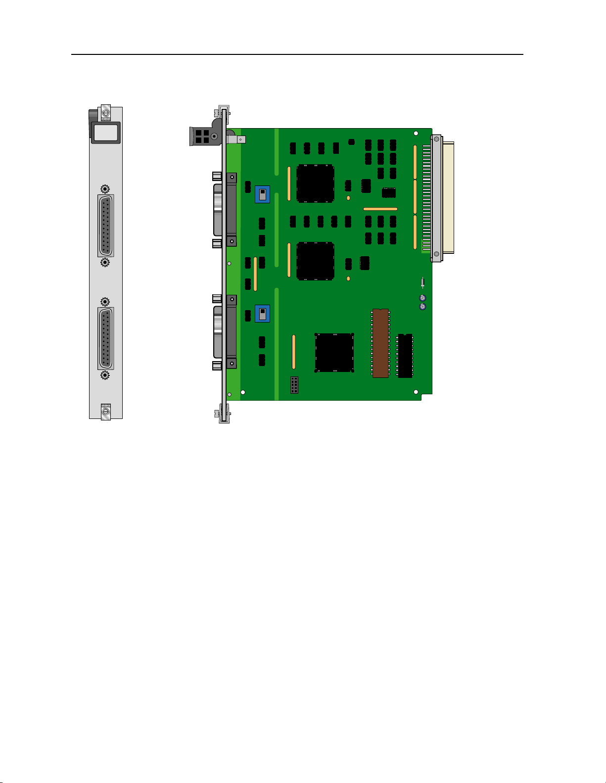
1.2.1.1 Two-Port HSU Card Jumper/Switch Settings
The HSU 530/35 Card has two slide switches that you must set for eithe r RS-530 or V.35
interfacing on its data ports. F igure 1-1 shows these switches, whic h are factory-se t to RS-530
operation (up positions) for both ports. To change a card port for V.35 operation, reset its
associated switch to the down position.
Data Cards IMACS System Release 5.1.6 1-1
Page 14
Running Head
HSU Cards HSU Card
HSU*2
530/35
Model No.
HSU RS530/V.35
P
1
Port #1
HSU RS530/V.35
P
2
Port #2
RS-530
V.35
RS-530
V.35
Figure 1-1. Two- Port HSU 530/35 Card Switches
Power
Bus
Edge
Connector
1.2.1.2 Installing the Two-Port HSU 530/35 Card
Install the Two-Port HSU 530/35 Card into any user card slots. These slots are U1 to U8 on
the two-sided chassis and front-loading chassis with power supplies on top, or P1 to P4 and
W1 to W4 on the front-loading chassis with power supplies on the side.
1.2.2 HSU-T V11 Card Description (820360)
The HSU-T V11 Card has two ports that c onnect to RS-530 or X.21 CPE devices. Each port
can operate as either DCE or DTE, with data speeds ranging from 56 or 64 kbps to 1.536 or
1.984 Mbps.
1.2.2.1 HSU-T V11 Card Jumper/Switch Settings
The HSU-T V11 Card main board does not contain any jumpers or switches.
1-2 IMACS System Release 5.1.6 Data Cards
Page 15

HSU Card HSU Cards
1.2.2.2 Installing the HSU-T V11 Card
Install the HSU-T Card into any user card sl ots. These slots are U1 to U8 on the two-sided
chassis and front-loading chassis with power supplies on top, or P1 to P4 and W1 to W4 on
the front-loading ch assis with power supplies on the side.
1.2.3 HSU 35 Card Description (821260)
The HSU 35 Card supports two V.35 data ports.
1.2.3.1 HSU 35 Card Jumper/Switch Settings
The HSU 35 Card doesn’t have any jumpers or switches on its mainboard.
1.2.3.2 Installing the HSU 35 Card
Install the HSU 35 Card into any user card slots. These slots are U1 to U8 on the two-sided
chassis and front-loading chassis with power supplies on top, or P1 to P4 and W1 to W4 on
the front-loading ch assis with power supplies on the side.
1.2.4 HSU-AD 530/35 Card Description (821360)
The HSU-AD 530/35 Card supports two RS-530 or V.35 CPE devices. The selection of
RS-530 or V.35 is made on a port-by-port basis using on-board switches as described below.
This card also supports V.25bis dialing (an inba nd dialing protocol) and RS-366 dialing
through separate DB-15 RS-366 jacks on the card. The HSU-AD 530/35 Card also has a
proprietary inband performance monitoring system.
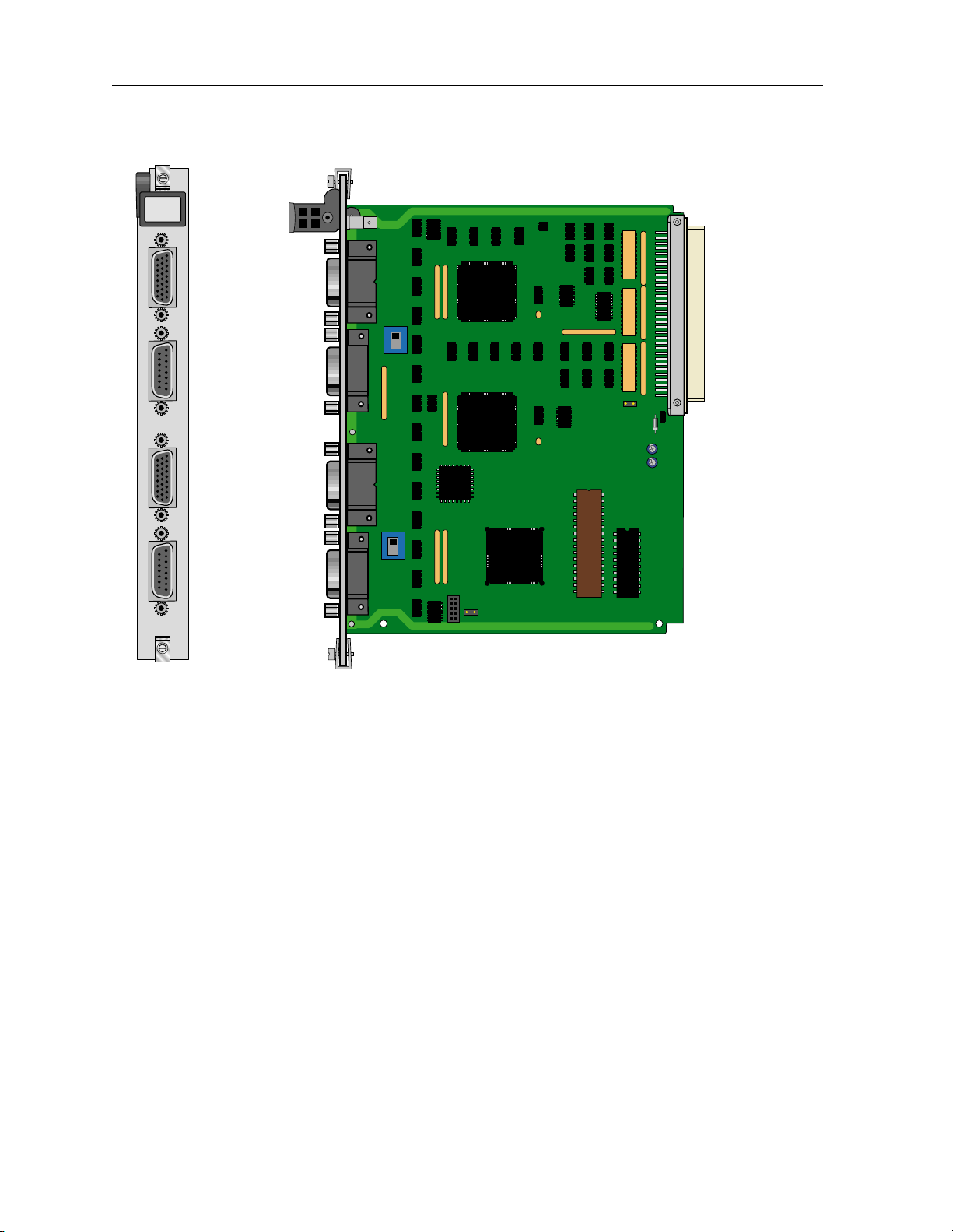
1.2.4.1 HSU-AD Card Jumper/Switch Settings
Set the car d switches for operation of ports 1 and 2 in either the RS-530 or V.35 mode. These
switches are shown i n Figur e 1-2; they are f act ory-set for RS-530 o peration . To change a port
to V . 35 operation, rese t its switch as shown. The ports can be set individually f or either RS-530
or V.35 operation, bu t once you se t t hem, they r emain i n that mode un til the sl ide swit ches are
reset. RS366 Dialing P ort #1 a nd RS366 Dia li ng Port #2 are diali ng ports for Port #1 and Por t
#2 (HSU RS530/V.35) respectively; they serve no other pur pose .
Data Cards IMACS System Release 5.1.6 1-3
Page 16
Running Head
HSU Cards HSU Card
HSU*4
AD530/35
P
1
HSU RS530/V.35
Port #1
RS-530
Model No.
Power
Bus
Edge
Connector
P
RS366 Dialing
2
V.35
Port #1
P
3
HSU RS530/V.35
Port #2
RS-530
P
4
RS366 Dialing
V.35
Port #2
Figure 1-2. HSU-AD 530/35 Card Switches
1.2.4.2 Installing the HSU-AD 530/35 Card
Install the HSU-AD 530/35 Card into any user car d slots. These slots are U1 to U8 on the
two-sided chassis and front-loading chassis with power supplies on top, or P1 to P4 and W1
to W4 on the front-loading chassis with powe r supplies on the side.
1.2.5 HSU-T V35 Card Descrip tion ( 821460)
The HSU-T V35 Card supports t wo V.35 CPE data devices . Each car d port ca n be config ured
to operate as either DCE or DTE, with data speeds ranging from 56 or 64 kbps to 1.544 or
2.048 Mbps.
1-4 IMACS System Release 5.1.6 Data Cards
Page 17
HSU Card HSU Cards
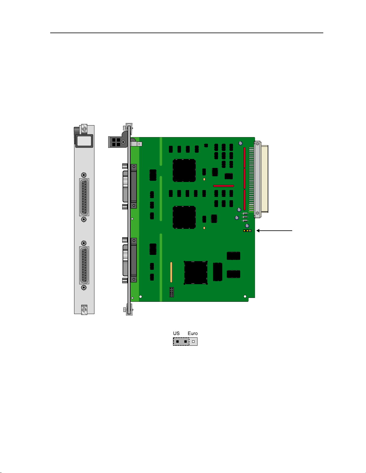
1.2.5.1 HSU-T V35 Card Jumper/Switch Settings
The HSU-T V35 Card must be set either to U.S. or European configuration by moving a
jumper located on JP3. Figure 1-3 shows this jumper. Setting the jumper on the left two pins
establishes the U.S. voltage configuration. Setting it on the right two pins establishes the
European voltage. This setting should match the configuration of your part icular chassis, or
the card will not operate properly. The factory default setting is US.
HSU-T
530/35
P
1
P
2
Figure 1-3. HSU-T V35 Card
1.2.5.2 Installing the HSU-T V35 Card
US/Euro
Jumper
Install the HSU-T V35 Card into any user card slot s. These slots are U1 to U8 on the two-sided
chassis and front-loading chassis with power supplies on top, or P1 to P4 and W1 to W4 on
the front-loading ch assis with power supplies on the side.
Data Cards IMACS System Release 5.1.6 1-5
Page 18

Running Head
HSU Cards HSU Card
Model No.
1.2.6 Four-Port HSU 530/35 Card Descrip tion (821570)
The four-port HSU 530/35 Card supports four RS530 or V.35 data ports. The selection of
RS-530 or V.35 is made on a port-by-port basis using on-board switc hes.
CAUTION!
If used in a system using a T1 “Line Code” other than “B8ZS,” HSU card
ports assigned to multirate circuits greater than or equal to 4 or more
consecutive time slots at 64kbps must have DTE connected to the port prior to
activatio n. Fa ilu re to atta ch DT E will caus e a fal se ca rri er alar m.
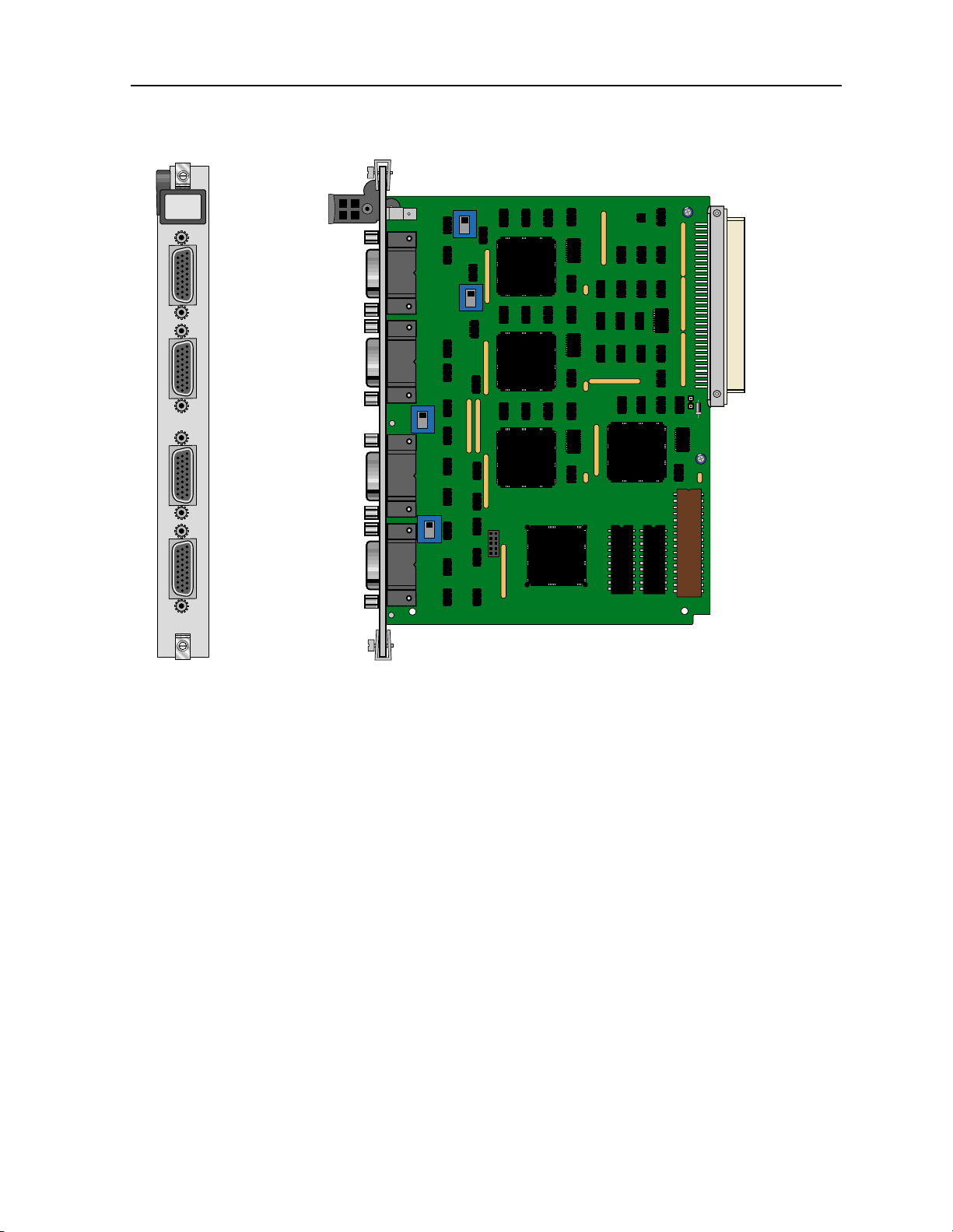
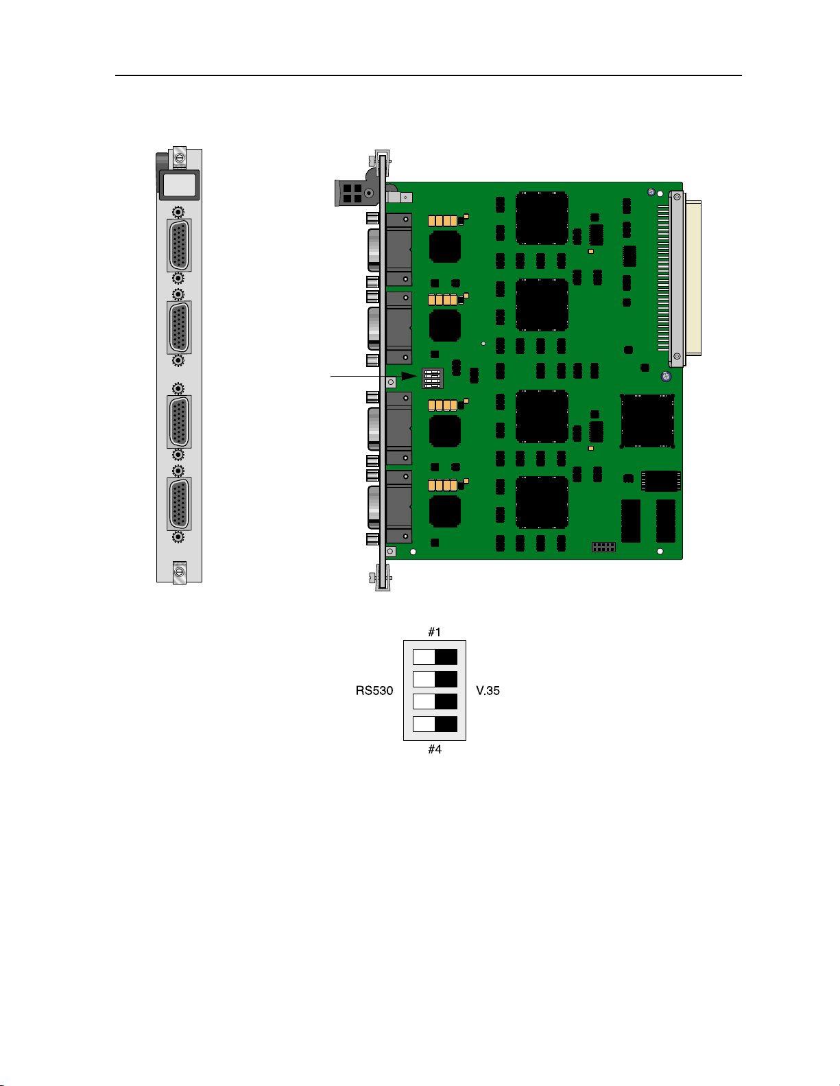
1.2.6.1 Four-Port HSU Card Jumper/Switch Settings
The four-p ort HSU 530/35 C ard has four s lide swi tches that mu st be set f or the pr oper type of
interface (either RS-530 or V.35) on ports 1 through 4 of the card. Figure 1-4 shows these
switches, which are f actory- set for RS-530 operatio n on both por ts. To change a port for V.35
operation, reset its associa ted swit ch as shown. Ports c an be set indi vidually f or eithe r RS530
or V.35 operation, but once set, they remain in that mode until the slide switches are reset.
Note: When setting switch to V.35 mode it unbalances the CTS Lead. It do es not chan ge the
voltage levels of the dri ver o utput. ( The Per sonali ty Module w ill do the same t hing as
setting the switch).
1-6 IMACS System Release 5.1.6 Data Cards
Page 19
HSU Card HSU Cards
HSU*4
530/35
HSU RS530/V .35
P
1
Port #1
HSU RS530/V .35
P
2
Port #2
P
HSU RS530/V.35
3
Port #3
P
4
HSU RS530/V.35
Port #4
RS-530
V.35
RS-530
V.35
RS-530
V.35
RS-530
V.35
Power
Bus
Edge
Connector
Figure 1-4. Four-Por t HSU 530/35 Card Switches
1.2.6.2 Installing the Four-Port HSU 530/35 Card
Install the Four-Port HSU 530/35 Card into any user card slots. These slots are U1 to U8 on
the two-sided chassis and front-loading chassis with power supplies on top, or P1 to P4 and
W1 to W4 on the front-loading chassis with power supplies on the side.
1.2.7 Four-Port HSU*4E 530/35 Car d Desc r ipt ion (8 21660)
The four-port HSU*4E 530/ 35 SS Card is an enhanced version of the 821570 card and
supports four E IA530/A or V.35 dat a ports. The se lection EI A530, EI A530A, or V.35 is made
on a port-by-port basis usi ng on-board switches.
Data Cards IMACS System Release 5.1.6 1-7
Page 20

Running Head
HSU Cards HSU Card
Model No.
CAUTION!
If used in a system using a T1 “Line Code” other than “B8ZS,” HSU card
ports assigned to multirate circuits greater than or equal to 4 or more
consecutive time slots at 64kbps must have DTE connected to the port prior to
activatio n. Fa ilu re to atta ch DT E will caus e a fal se ca rri er alar m.
1.2.7.1 Features of the Four-Port HSU*4E 530/35 Card (821660)
This enhanced HSU card is a derivative of the 8215 70 card, wi th better clock pe rformance and
a true V.35 interface. The functionality of the 821660 will be the same as the 821570 except
for the addition of a receiver clock invert option.
The 8216xx can be used in any DDS application where the circuit ha s many timeslots (>24).
The enhanced clock jitter provides better tail-circuit performance. Additionally, the transmit
and receive clock edges can be individually selected (refer to Tx and Rx CLOCK PLRTY
descriptions lat er in this chapter).
1.2.7.2 Four-Port HSU Card Jumper/Switch Settings
The four-port HSU*4E 530/ 35 SS Card has a dip switch that must be set for the proper type
of interface ( either RS-530 o r V.35) on por ts 1 thr ough 4 of the c ard . Figure 1-5 s hows the d ip
switch, which are factory-set for RS-530 operation on both ports. To change a port for V.35
operation, reset its associated switch as shown.
Ports can be set indi vidually for either RS530 or V.35 operation, but once set, they remain in
that mode until the slide switches are reset.
1-8 IMACS System Release 5.1.6 Data Cards
Page 21
HSU Card HSU Cards
HSU*4E
530/35
P
1
HSU RS530/V.35 Port #1
P
2
HSU RS530/V.35 Port #2
See below
P
3
HSU RS530/V.35 Port #3
P
4
HSU RS530/V .35 Port #4
Figure 1-5. Four-Port HSU*4E 530/35 SS Card Switches
1.2.7.3 Installing the Four-Port HSU*4E 530/35 Card
Install the Fou r-Port HSU*4E 530/35 Card into any user card slots. These slots are U1 to U8
on the two-sided c hassis and front- loading chass is with power su pplies on top, or P1 to P4 and
W1 to W4 on the front-loading chassis with power supplies on the side.
Data Cards IMACS System Release 5.1.6 1-9
Page 22
Running Head
HSU Cards HSU Card
Model No.
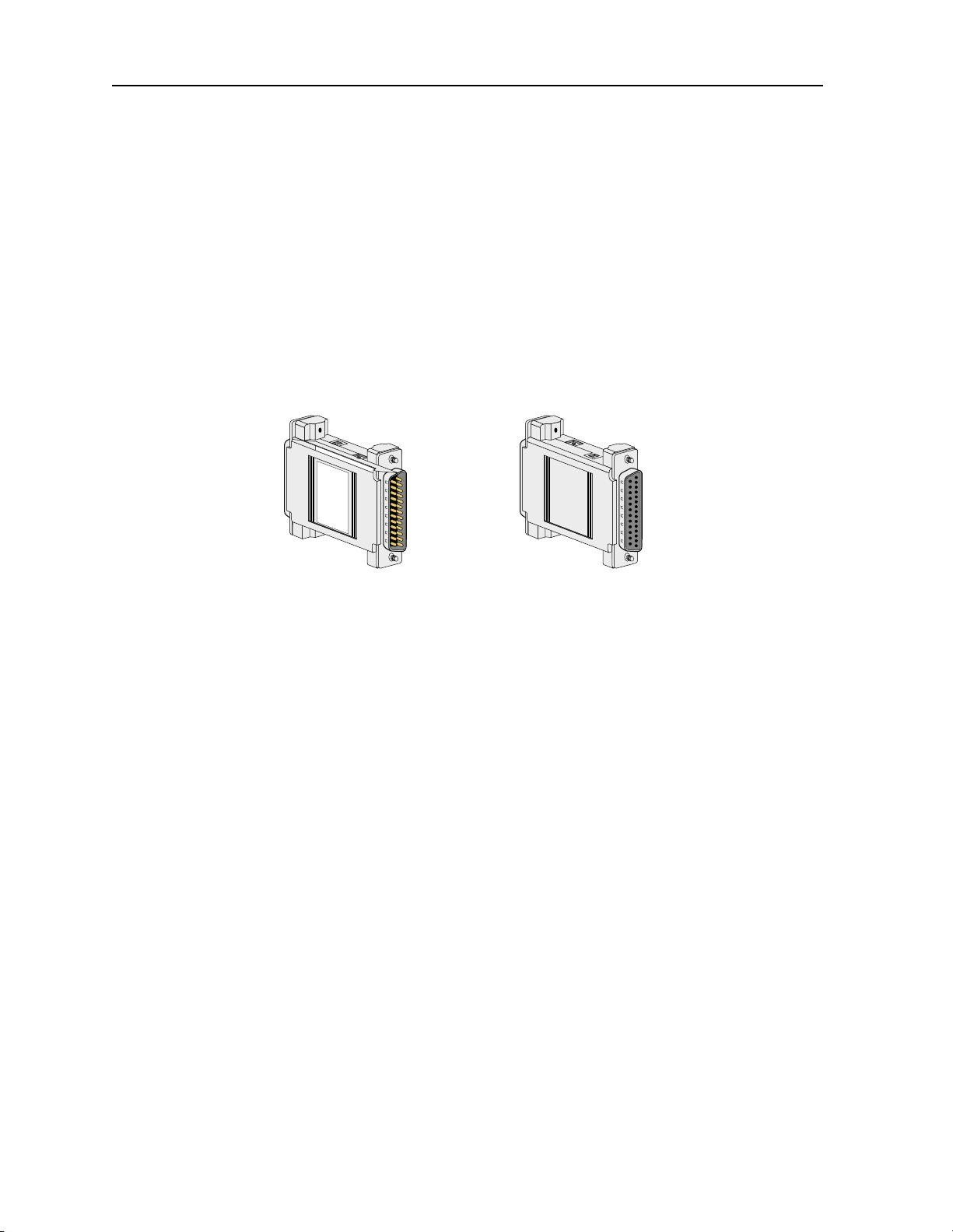
1.2.8 V.35 Personality Mo du le (1251)
When using the two-port HSU 530/35, HSU-AD 530/35, and four-port HSU 530/35 Cards,
you may want to connect the RS-530 output jack to RS-232 external equipment (for all of
these cards). The V.35 Personality Module is a adapter module that plugs into the female
DB-25 port and connectors, then atta ches via a male/female connector to the external CPE
device. Figure 1-6 shows this module.
Note: The CPE connection cables should be less than 25 feet long. For RS232 operation,
the re commended maximum cabl e length is l ess than 25 feet , and the speed should not
exceed 56 kbps .
DB25 Male-Female
(Male view)
DB25 Male-Female
(Female view)
Figure 1-6. V.35 Personality Module
The three HSU 530/35 Cards also have internal switch settings for changing signals from
RS-530 to V.35 format, as previously desc ribe d. You must also set those switches for RS-530
interfacing when atta chi ng personality modules to the associated card ja cks.
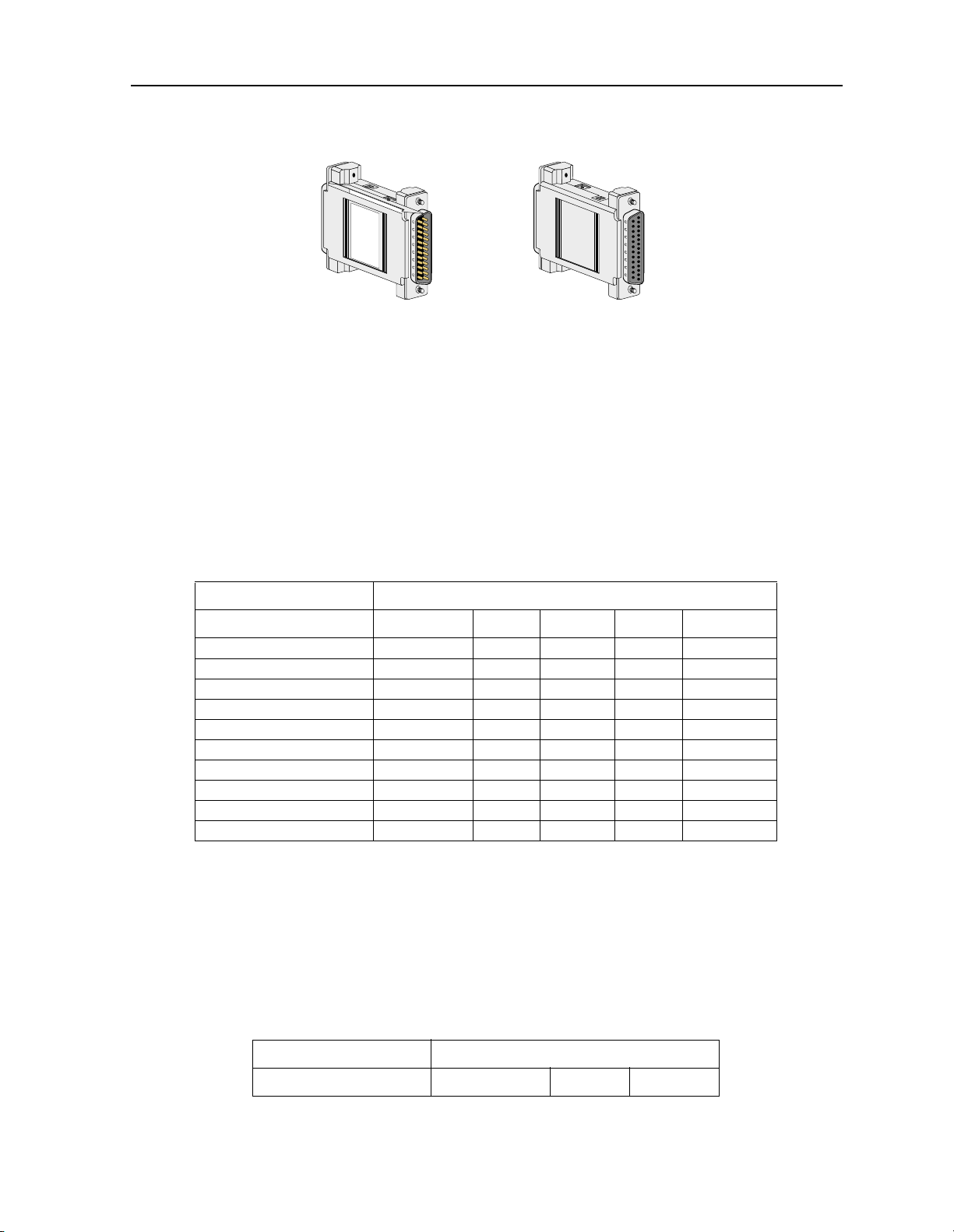
1.2.9 RS-232-E Perso na lit y M od u le Des cri pti on (125 3)
The RS-232-E Per sonality Module converts 530-A signals to RS-232-E format which allows
the HSU Cards to interoperate with equi pment employing an interface conforming to the
ANSI/EIA/TIA-232-E electr ical characteristic s. Fi gure 1-7 shows this module.
1-10 IMACS System Release 5.1.6 Data Cards
Page 23
HSU Card HSU Cards
DB25 Male-Female
(Male view)
Figure 1-7. RS-232 Personality Module
1.2.10 HSU Card Cables
T able 1-1, Table 1-2, and Table 1-3 represent a matrix used for co nnecting cables to HSU
Cards for DTE and DCE transm it clocking. The follo wing HSU Cards apply (820260, 820360,
821260, 821360, 821460, 821570 and 821660).
Table 1-1. HSU to Cable Matrix (To DTE Clock)
HSU CARD TO A DTE THAT ACCEPTS CLOCK
820260 NO SWITCHES 1252/1221* 1212F/M 1204F/M 1203F/1251
820260 WITH S W ITCHES 1252/1221* 1212F/M 1204F/M 1261F/M
820360 DCE 1252/1221* 1212F/M 1204F/M 1261F/M
820360 DTE
821260 1203F/M
821360/821560/821660 1264F/1253** 1206F 1265F/M 1264F/M 1263F/M
821460 DCE 1260F/M
821460 DTE
2 PORT EXT. CABLES 1221 1222 1224
4 PORT EXT. CABLES 1269 1268
DB25 Male-Female
(Female view)
RS232 RS366 RS449 RS530 V.35
*820260/820360 Switches set to RS-530 and 1252 Connected to HSU Card
**The 1253 Connects to the end of the 1264F Cable
1253 is a New Version of the 1252 and can replace a 1252.
Table 1-2. HSU to Cable Matrix (To DCE Clock)
HSU CARD TO A DCE THA T ACCEPTS CLOCK
RS449 RS 530 V.35
Data Cards IMACS System Release 5.1.6 1-11
Page 24

Running Head
HSU Card User Screens and Settings HSU Card
820260 NO SWITCHES 1212X 1204X 1203X/1251
820260 WITH SWITCHES 1212X 1204X 1261X
820360 DCE 1212X 1204X 1261X
820360 DTE
821260 1203X
821360/821560/821660 1265X 1264X 1263X
821460 DCE 1203X
821460 DTE
2 PORT EXT. CABL ES 1222 1224
4 PORT EXT. CABL ES 1269 1268
Model No.
Table 1-3. HSU to Cable Matrix (DCE Provides Clock)
HSU CARD DCE PROVIDES CLOCK
RS530 V.35 RS449
820260 NO SWITCHES
820260 WITH SWITCHES
820360 DCE
820360 DTE 1204X 1211
821260
821360/821560/821660
821460 DCE
821460 DTE 1260F/M
2 PORT EXT. CABLES
4 PORT EXT. CABLES
1.3 HSU Card User Screens and Settings
The HSU Cards permit configuration and operation through use of several user screens and
optional setting s.
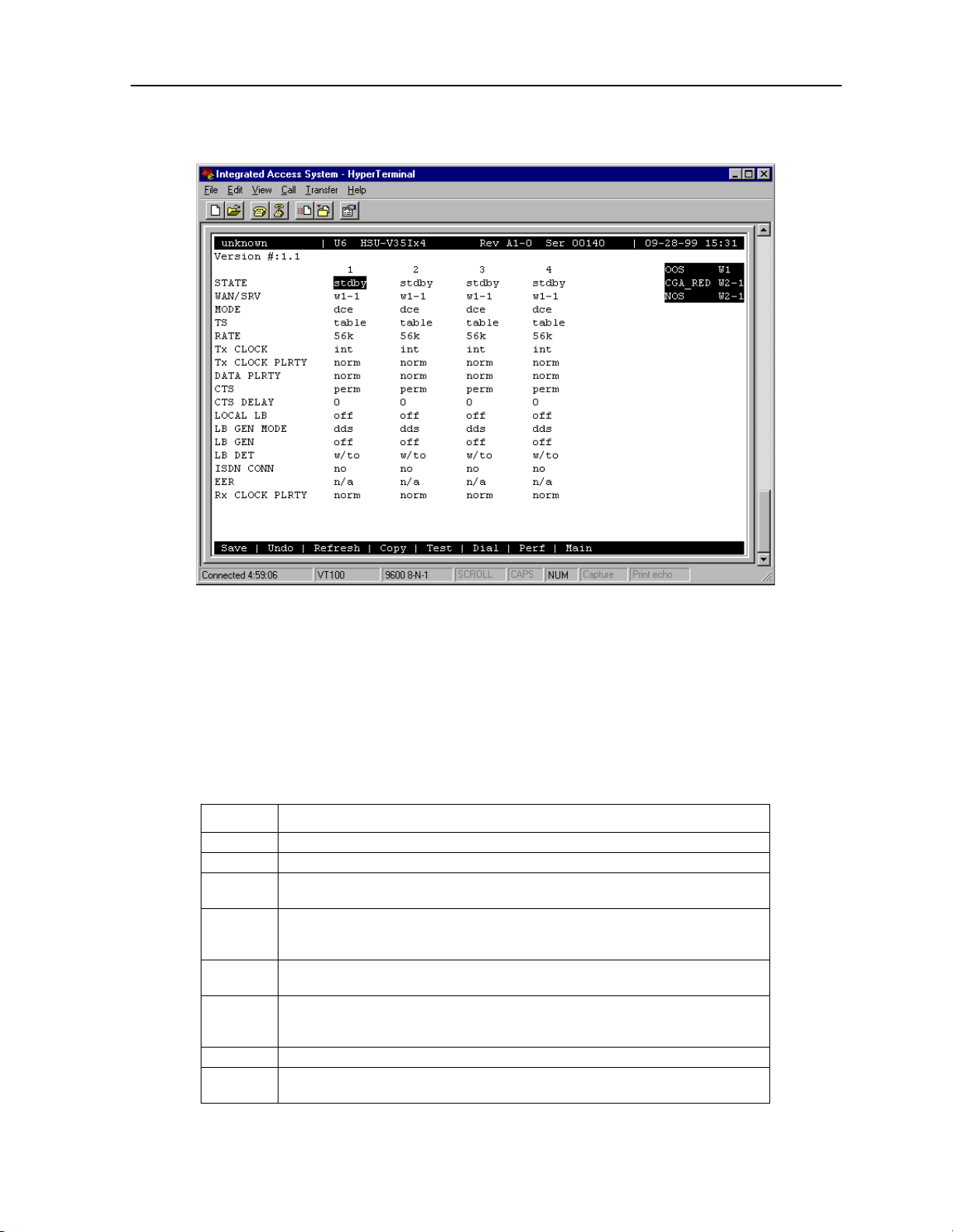
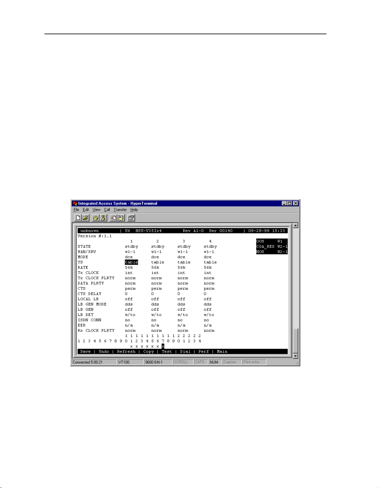
1.3.1 HSU Card Main Screen
You must configure the HSU Card ports for operation. Confi guration can be performed f rom
the HSU Card Main Screen, which is shown in Figure 1- 8. T o access that screen, highlight the
desired card in the Syste m Main Scr een and pr ess <Enter>. The scr een displayed in Fi gur e 1-8
shows the 821660 HSU Card. See the notes in Table 1-5 for other HSU Card settings.
1-12 IMACS System Release 5.1.6 Data Cards
Page 25
HSU Card HSU Card User Screens and Settings
Figure 1-8. Typical HSU Card Main Screen
The bottom highlighted line on this screen lists several actions you can perform from the
screen. To perform an operation, simply press the upperca se lette r as sociated with t he desired
action. For example, to sa ve your option se ttings, ty pe “s”. Table 1-4 lists the actions you can
perform.
Table 1-4. HSU Card Main Screen Actions
Action Function
Save Saves changes to settings.
Undo Returns all settings to the last saved state.
Refresh Updates certain time-related information fields that are not automatical ly
updated (i.e., pe rform ance and test data).
Copy Copies the contents of the cu rrent column to the next column. Usef ul if you
change a lot of entries in one column and want to repeat those changes in
subsequent columns.
Test Initiates and monitors testi ng of all HSU Card ports. Refer to the Test section
Dial Allows you to identify the HSU port by telephone number, download and
Perf Brings up the Performance Data Screen.
Main Returns to the Sys tem Main Screen. If changes are made to settings and not
of this chap ter.
modify call profiles from the Interface card, and dial and broadca st I SDN
calls.
saved, you will be prompted to save or lose changes.
Data Cards IMACS System Release 5.1.6 1-13
Page 26

Running Head
HSU Card User Screens and Settings HSU Card
Model No.
Table 1-5. HSU Card Setting Options and Defaults
Parameter User Options Notes Default
STATE stdby actv stdby
WAN/SRV wan serv user 1 w1-1
MODE dce dte 5 dce
TS table 2 table
RATE 64k 56k 56k
TX CLOCK int ext int
Tx CLOCK PLRTY norm inv 7 norm
DATA PLRTY norm inv norm
CTS perm rlocal ignor local perm
CTS DELAY 0 30 60 100 0
LOCAL LB off dte net off
LB GEN MODE dds v.54 ft1 dds
LB GEN off ocu csu (csu-1, csu-2) dsu ds0 (ds0-1, ds0-2) 3 off
LB DE T w/to on of f w/to
ISDN CONN no 4 no
EER off on none 10e
Rx CLOCK PLRT Y norm inv 7 norm
-4
- 10e
-9
6 none
Notes:
1. The WAN/SRV parameter has three optional choices: wan, serv and user. In wan
mode, the options are w1-1 through w4-2. In serv mode, the option are P1-P3 and in
user mode, the options are U1-U8 (Port 1-4).
2. If the WAN selected above has a CSU or DSX module connected, the values range from
1-24. If a CEPT module is inst all ed the val ues are 1- 31.
3. These options are only valid if the Loopback Gen eration Mode selected is dds. If the
Loopback Generation Mode is v.54 or ft1, then the LB G E N opt i ons are off and on.
4. This is an information-only field, there are no user selections.
5. DTE mode is only for HSU-T (8203, 8214).
6. Displays only for HSU-AD 530/35 (8213).
7. Displays only for HSU*4E 530/35 (8216). For other models the parameter will display
CLOCK PLRTY.
1-14 IMACS System Release 5.1.6 Data Cards
Page 27

HSU Card HSU Card User Screens and Settings
STATE
The State setting de termines whether the port is active or inactive . An inactive port does not
occupy time slots on a WAN link. Set State to standby (stdby) for ports you are not using or
have not yet configured. Set it to active (actv) for ports that are ready for use. The control leads
assume the status shown in Table 1-6 for the different states.
Table 1-6. HSU Card State Status
Control Leads Active WAN Link Down St andby
RLSD High or follows remote RTS Low Low
DSR High High Low
CTS Definable Definable High
WAN/SRV
The WAN/SRV setting identifies the card to which the output of this port is direc ted. If wan
is chosen, the data fr om this car d port will be dir ected t o a WAN port (the options are w1-1 to
w4-2).
If user is chosen, the data will be routed to another HSU Card. First, highlight the selected
user slot (U1 to U8). Then, if there is a compatible HSU Card in that slot, the system will ask
for the number of the port to whic h you want to conne ct (1 to 2 or 1 to 4). Type in the number
of the port desired. If a number higher tha n the possible number of available ports is chosen
(e.g., 9), the system will automatically select port 1 on the destinati on user car d.
Note: The serv setting is not available for the HSU-T V11 and HSU-T 35 Cards.
MODE
The Mode paramet er appears only for the HSU-T V11 and HSU-T 35 Cards. It allows you to
identify how the HSU port appears to the devic e on the other end of the interface cable. The
dce option causes the port to be recognized as a DCE (data circuit-ter minating equipment)
device. The dte option causes the port to be recognized as a DTE (data terminal equipment)
device.
Note that th e choices appea ring for s ome of the parameters that follow will depend on whe ther
you choose dce or dte as the Mode. Those parameters and their available settings are
described below.
Data Cards IMACS System Release 5.1.6 1-15
Page 28
Running Head
HSU Card User Screens and Settings HSU Card
Model No.
TS
The TS (time slot) setting identifies the time slots on the WAN link when wan is the
W AN/S R V setting. Unlike other user cards, the HSU Card can use many time slots on a single
WAN port to create a super-rate circuit for an individual HSU port. One or all DS0 time slots
on a single T1 or E1 link c an be assembled for use by an HSU port in order to sa tisfy the speed
requirements of the DTE.
The time slot numbers r ange from 1 to 24 for T1 links and 1 to 31 fo r E1 li nks. Howe ver , ti me
slot 16 is not avail able on E1 links pr ogrammed f or CAS or CCS si gnaling. Figure 1- 9 shows
the display when table is selected. Using the space bar to select and desele ct the time slot, this
example shows time slots 1 1 to 16 on WAN 1-1 assigned to this port. The time slot
assignments do not have to be contiguous on any card por t.
Note: Do not change this parameter when the HSU Car d is linked to an ISDN-PRI
connection.
Figure 1-9. Typical HSU Port Time Slot Assignment Screen
1-16 IMACS System Release 5.1.6 Data Cards
Page 29

HSU Card HSU Card User Screens and Settings
RATE
The Rate setting all ows you to select the band width for all time slo ts assigned to th is port. The
available opt io ns are 56k or 64k. This selection is multiplied by the number of time slots
assigned to the port, to define the ove rall port speed. For example, if you choose 64k as the
port Rate and assign four time slots to that port, the overall port speed is 256 kbps.
Tx CLOCK
The Transmi t Clock (Tx CLOCK) setting identifies the clock source for the SD (send data)
signal from the external CPE. The int (internal) setting requires an external DTE to
synchronize its tran smitted data with the clock on the SCT leads. The ext (extended) setting
requires the DTE to synchronize its transmitted data with the clock on the SCTE leads.
Use ext with a l ong cable run t o ensur e th e dat a and clock a re in- phase when th ey arr ive at the
system. The DTE must loop back the clock on the SCT leads to the SCTE leads.
If ext is select ed but the system does not detect an incoming c lock on the SCTE leads, the HSU
Card automatically gene rate s an internal clock. If this clock is not synchronized with the
incoming data, reset the CLOCK PLRTY option to synchronize the clock and data. The Tx
CLOCK PLRTY option settings are described in the next paragraphs.
On the HSU-T V11, HSU-T 35 and HSU* 4E 530/35 SS Cards, the T ransmi t Clock option can
be set only if the Mode for the card port is set to dce. The default TX Clock setting in the dce
mode is int. For a dte port, the only available setti ng is n/a.
Tx CLOCK PLRTY (821660 card)
The Transmi t Clock Polarity (Tx CLOCK PLRTY) setting provides another way to
compensate for long c ables in th ose cases where the DTE equipmen t does not p rovide SCTE.
When you choose inv (inverted mode), the r elationship between the clock and data is altered
to compensate f or long cable r uns that th e data signa ls must trav erse between the card por t and
CPE. When you choose norm (normal), the relationship between the clock and data is
unchanged. If you use inv, set the Tx CLK (Transmit Clock) option above to int (internal).
On the HSU-T V11, HSU-T 35 and HSU*4E 530/35 SS Cards, the Clock Polarity setting
above can be set on ly if the port Mode is set t o dce. The default setting in that node is norm.
For a dte port, the only available setting is n/a.
DATA PLRTY
The Data Polar ity (DAT A PLR TY) opt ion allows you to eithe r send all data bits to t he networ k
as normal ones and zeros, or to invert all bits in the transmitted data stream. Choose norm
(normal) to leave the transmi tte d data intact; or, ch oose inv (inverted) to invert all outgoing
data. This can be helpf ul in ensuring m inimum-one s densi ty tra nsmission over T1 links whe n
Data Cards IMACS System Release 5.1.6 1-17
Page 30

Running Head
HSU Card User Screens and Settings HSU Card
the data contains long stri ngs of zeros. Inverting the zeros reduces the like lihood that the
composite T1 stream will not meet minimum-one s densit y require ments. Bot h systems of t he
end-to-end HSD circuit path require the same DATA PLRTY option setting.
On the HSU-T V11 and HSU-T 35 Cards, the Da ta P olarity opti on i s ava ilable o nly if the port
Mode is set to dce. The default settin g in that mode i s norm. For a dte por t, t he only avai lable
setting is n/a.
Model No.
CTS
The Clear To Send (CTS) setting controls when data is sent. Some DTE equipment must
receive a CTS signal before transmitting data. Set the CTS option to perm (permanent) t o
make CTS permanent ly High (asse rted). Choose rlocal (remote-loc al) to allow R TS to control
both CTS on the local DTE device and RLSD on the remote DTE device.
Choose to ignor (ignore) to always force CTS Low (negated). Set the CTS option to locl
(local) to make CTS follow RTS from the local DTE.
On the HSU-T V11 and HSU-T 35 Cards, the CTS settings are used only if the port Mode is
set to dce. The default setting in that mode is perm. For a dte port, the only available setting
is n/a.
CTS DELAY
The Clear To Send (CTS) Delay setting delays changes in the CTS signal in the local mode.
Enter the value you need in millisec onds. The available options are 0, 30, 60, and 100 ms. If
you do not know what value you ne ed, s tart with 0 (z ero) ms and i ncreas e the value gr adua lly
until you no longer e xper ience problems. The CTS opti on above m ust be set to locl before the
CTS DELAY setting has any effe ct.
On the HSU-T V11 and HSU-T 35 Cards, the CTS Delay settings are used only if the port
Mode is set to dce. The default setting in that mode is 0 (zero). For a dte port, the only
available setting is n/a.
LOCAL LB
The Local Loopback (LOCAL LB) option activates a loop back on the selected card port.
Choose the dte setting to loop the outgoing data from the external DTE device back to the
DTE receiver . This loopba ck (see Figure 1-10) allows you to check the loca l cabling and most
of the circuitry in the HSU Card. It also disconnects the incoming data from the far end.
1-18 IMACS System Release 5.1.6 Data Cards
Page 31

HSU Card HSU Card User Screens and Settings
HSU Card
HSU
Port
DS-0
PCM Bus
T1/E1
Network
Figure 1-10. Local DTE Loopback
Choose the net (network) se tting t o loop the inc oming da ta fr om the network ba ck towar d the
far end. This loopback is shown in Figure 1-11 . It tests some of the local HSU Card circuitry,
the local system common car ds, the WAN link card, the fa r-end HSU Card and CPE device,
and the WAN link between the two sites. The net setting also drops the Data Set Rea dy (DSR)
control signal output on the HSU port.
HSU Card
HSU
Port
DS-0
PCM Bus
T1/E1
Network
Figure 1-11. Local Network Loopback
Data Cards IMACS System Release 5.1.6 1-19
Page 32

Running Head
HSU Card User Screens and Settings HSU Card
On the HSU-T V11 and HSU-T 530/35 Cards, the same choices above appear if the port Mode
is set to dce. For a dte port, the choices are dce, local, and off. The dce loopback is
functionally identical to the dte loopback depicted in Figure 1-10, and the local loopback is
the same as the net loopback depicted in Figure 1-11.
Model No.
LB GEN MODE
The Loopback Generati on Mode (LB GEN MODE) sett ing define s the type of inband loop-up
and loop-down codes that will be sent to the remote equipment. Three industry-standard codes
are supported: dds , whic h sends a DDS-compatible latching loopback code in each of the
DS0s that make up the circuit; v.54, which is compatible with CCITT V.54 standard and ft1,
which is compatible with ANSI Fra ctional T1 sta ndard s. The final option, perf (performance
data), activates an 8 kbps performance data monitoring channel (isolated from the total
bandwidth of the circuit) that collects end-to-end performance statistics from a local HSU
Card to a remote HSU Card.
On the HSU-T V11 and HSU-T 35 Cards, the same choices above appear if the port mod e is
set to dce. For a dte port, thi s setting is always n/a.
LB GEN
If you selected v.54, ft1, or perf as the Loopback Generation (LB GEN) mode setting, the
Loopback Generation setting a llows you to send an on (loop-up comman d) or off ( loop-d own
command). If you selected dds as the Loopback Generation mode, this setting allows you to
define the type of DDS loopba ck that you wish to generate. The four options are ocu (Office
Channel Un i t), dsu (Data Servic e Unit ), csu (Channel Service Unit), and ds0 (a full 64 kbps
loopback). Figure 1-12 through Figure 1-14 show where these loopbacks oc cur. You can also
turn all DDS remote loopbacks off.
Note that you cannot per form loop-up and loop-down c ommands on more than one port of the
same card simultaneously. Y ou must finish all loopback operations on one port before starting
them on another port.
On the HSU-T V11 and HSU-T 530/35 Cards, the same choices shown above appear if the
port Mode is set to dce. For a dte port, the choi ces are llb (local loopback), rlb (remote
loopback), and off. The llb setting loops the incoming signal from the network back toward
the network and far e nd. This loop back occ urs at the HSU- T V1 1 or HSU-T 35 Card. The rlb
performs the same loopback at the far - end card.
1-20 IMACS System Release 5.1.6 Data Cards
Page 33

HSU Card HSU Card User Screens and Settings
Local
DTE
Local System
HSU Card
Carrier's DDS
Network
Remote System
OCU-DP Card
Local Site Remote Site
Figure 1-12. Remote OCU or DS0 Loopback
Local
DTE
Local System
HSU Card
Carrier's DDS
Network
Remote System
OCU-DP Card
CSU DSU
CSU DSU
Remote
DTE
Remote
DTE
Local Site Remote Site
Figure 1-13. Remote CSU Loopback
Local System
HSU Card
Local
DTE
Carrier's DDS
Network
Local Site Remote Site
Remote System
OCU-DP Card
Figure 1-14. Remote DSU Loopback
CSU DSU
Remote
DTE
Data Cards IMACS System Release 5.1.6 1-21
Page 34

Running Head
HSU Card User Screens and Settings HSU Card
Model No.
LB DET
Depending on the selection you made for the Loopback Gener ation mode above, the HSU
Card port will respond to any of the loopback cod es genera ted by a remote system. The
Loopback Detection ( LB DET) setting lets you enable or disable this c apability on each card
port. However, this setting does not affect local loopback commands from a local control
terminal.
Choose off to have the system ignore remote loopback commands. Choose on to make the
system monitor the car d ports for l oopback commands se nt from the remote equip ment. Note
that the system will detect only the loopbacks in the format selected as the LB GEN mode.
When the system detects a loopback code, it loops the data back until the remote equipment
releases the loopback. The w/to (with time-out) setting is the same as on, except that after 10
minutes the system automatica lly releases the loopbacks initiate d by the remote equipment.
On the HSU-T V11 an d HSU-T 35 Cards, the same choices above appe ar only if the port Mode
is set to dce. For a dte port, this sett ing is always n/a.
ISDN CONN
This option is not available with this host release.
EER (821360 card)
The Excessive Error Rate (EER) parameter is only available on the HSU-AD 530/35 Card.
This setting defines an error rate threshold which, when exceeded, causes an alarm to be
declared. If the number of errors exceeds this threshold, an E will be placed in the Status
Column of the card’s Performance Monitoring Screen. The available options are from 10e-4
(one error i n 10,000 bits) to 10e-9 (one error in 1,000,000,000 bits) , or none. Choose none if
you do not want to report alarms for excessive error rates.
Rx CLOCK PLRTY (821660 card)
The Receive Clock Polarity ( Rx CLOCK PLRTY) setting provides anothe r way to
compensate for long c ables in th ose cases where the DTE equipmen t does not p rovide SCTE.
When you choose inv (inverted mode), th e relationship between the clock and data is altered
to compensate f or long cable r uns that th e data signa ls must trav erse between the card por t and
CPE. When you choose norm (normal), the relationship between the clock and data is
unchanged. If you use inv, set the Tx CLK (Transmit Clock) option above to int (internal).
Only the HSU*4E 530/35 SS Card suppor ts this para meter. For all other HSU’s this sett ing is
n/a. The default setting in that node is norm. For a dte port, the only available setting is n/a.
1-22 IMACS System Release 5.1.6 Data Cards
Page 35

HSU Card HSU Card User Screens and Settings
1.3. 2 HSU Car d Te st Screen
Selecting “Test” from the HSU Card Main Screen will access the Test Screen shown in Figure
1-15. From this screen, you c an create test si tuations between HSU Cards, or between a single
card and test e quipment at a remote site. Table 1-7 lists the actions you can perform from the
bottom line of this sc reen, and Table 1-8 lis ts the setti ngs pr esented on t his scr een, along with
their possible and default values.
Figure 1-15. Typical HSU Card Test Screen
Table 1-7. Test Screen Actions
Action Function
Save Saves changes to settings.
Undo Returns all settings to the last saved state.
Refresh Updates certain time-related information fields that are not automatical ly
InsertErr Allows you to manually insert a single error into the clear data signal.
Clear Clears the Test Scr een and resets all counters to zer o .
Main Returns to the HSU Card Main Sc reen. If c hang es ar e m ade to se tti ngs an d not
updated (i.e., pe rform ance and test data).
saved, you will be prompted to save or lose changes.
Table 1-8. Test Screen Option Settings and Defaults
Data Cards IMACS System Release 5.1.6 1-23
Page 36

Running Head
HSU Card User Screens and Settings HSU Card
Model No.
Parame ter User Optio ns Notes Default
BERT off mark space 1:1 1:7 511 qrss
2047 ds0 ff 7e 32 40 ocu-a csu-a
dsu-a csu1a csu2a
CTS norm off on norm
RLSD norm off on norm
DSR norm off on norm
SYNC information only–no user options
BE information onl y–no user options
ES information onl y–no user options
SES information only–no user options
OSS information onl y–no user options
BER information only–no user options
ELAP information onl y–no user options
R TS information only–no user options
DTR information only–no user options
LB ST information onl y–no user options
1off
Notes:
1. The following BERT settings are available only on the four-port HSU 530/35 Card:
ds0, ff, 7e, 32, 40, oc u-a, dsu-a , csul-a, and csu2a. These sett ings ar e not avail able on
the HSU-T V11 and HSU-T 35 Cards.
BERT
The Bit Error Ra te Tester (BERT) sends a data pattern and measu re s the bit error rate (BER)
on the selected HSU port. The patterns that can be select ed are off, mark (1111), space ( 0000),
1:1 (1010 alternatin g), 1:7 (0100-0000), 511 (511 test pattern), qrss (qua si-random signal
source), and 2047 (2047 test pattern).
On the four-port HS U 530/35 Card, selecting the ds0 pattern will display another set of BER T
patterns. Additional non-latching loopback patter ns are ff ( 111 1 -1111), 7e (0111-1110), 32
(0011-0010), 40 (0100-0000), ocu-a (ocu-alternating byte), csu-a (csu-alternating byte),
dsu-a (dsu-alternating byte), csu1a (csu–one r epeater–alternating byte), and csu2a (csu–two
repeater–alte rnating byte). The results of the alternating patterns ( ocu-a, csu-a, dsu-a, csu1a
and csu2a) appear in the Test Screen.
Also note that the Bit Err or Rate Tester is supported on the HSU-T V11 and HSU-T 35 Cards
only if the port mode is set to dce in their C ar d M ain Screen s .
1-24 IMACS System Release 5.1.6 Data Cards
Page 37

HSU Card HSU Card User Screens and Settings
CTS
The Clear T o Send (CTS) option allows you to define whether the CTS control lead should be
held on (high, asserted ) or off (low , negated). Selecting either on or off will override the
selection made in the HSU Card Main Screen. The third option is norm (normal), which
allows CTS to operate in the mode selected in the HSU Card Main Screen. Not available for
820360/821460 when DTE is selected.
RLSD
The Receive Level Signal Detect (RLSD) option allows you to define whether the RLSD
control lead is held on (high) or off (low). The third option is norm (normal), which means
that RLSD will be have as desc ribed in T able 1- 8. Not availab le for 820360/ 821460 when DT E
is selected.
DSR
The Data Set Rea dy (DSR) option allows you to define whether the DSR control lea d should
be held on (high) or off (low) . The thir d opti on is norm (normal), which means that DSR will
behave as described in Table 1-8. Not available for 820360/821460 when DTE is selected.
SYNC
The Synchronization fie ld indicates if the integrated BERT has achieved synchronization
either with itself via a remote loopback or with the remote test equipment. This is an
information-only f ield; it is not user-configu rable.
BE
The Bit Error (BE) field indicat es the tota l number of bit errors logged. This is an
information-only f ield; it is not user-configu rable.
ES
The Errored Seconds (ES) field indicates the total number of seconds in which errors were
detected. This is an information-only field; it is not user -configurable.
SES
The Severely Errored Seconds (SES ) field indica tes the tot al number of seconds in which the
bit error rate exceeded one bit per thousand (1 x 10⁻³). This is an information-only field; it is
not user-configurable.
Data Cards IMACS System Release 5.1.6 1-25
Page 38

Running Head
HSU Card User Screens and Settings HSU Card
Model No.
CSES
The Consecutive Severely Er rored Se conds (C SES) f ield i s t riggered b y th e occur ren ce of ten
consecutive Sever ely Errored Seconds. Once triggered, this field will increment (by one) f or
each elapsed second unt il the system logs ten consecut ive non-Severely Errored Seconds. This
is an information-only field; it is not user-configurable.
OSS
The Out of Synchronization Seconds (OSS) field indicates the number of seconds that the
HSU BERT has been out of synchronization. This is an information-only field; it is not
user-configurable.
BER
The Bit Error Rate (BER) field indicates the rate at whic h errors are being logge d. The system
calculates BER by dividing the number of bit errors (BE) by the total number of bits
transmitted during the test. This is an information-only field; it is not user-configurabl e.
ELAP
The Elapsed time (ELAP) setting indicates the running tally of the total number of seconds
during the test. This is an information-only field; it is not user- configurable.
RTS
The Request T o Send (R TS) field indicates the current status of the RTS control lead. The two
values that can be displayed are on and off. This is an information-only field; it is not
user-configurable.
DTR
The Data Terminal Ready (DTR) field indicates the current status of the DTR control lead.
The two values that can be displayed a re on and off. This is an information- only field; it is not
user-configurable.
The DTR field will always indicate on for the HSU 35 Card (Revision A and earlier), but it
will toggle between off an d on all other HSU Cards.
1-26 IMACS System Release 5.1.6 Data Cards
Page 39

HSU Card HSU Card User Screens and Settings
LB ST
The Loopback State (LB ST) field indic ates whether there are any remotely-initia ted
loopbacks currentl y active on the HSU port. This field displays both latching and non-latchin g
loopbacks initiate d from a remote device via in-band loop-up co des . I n addition to none, the
six messages that can be displayed in that field are l-ocu, l-dsu and l-csu for latching
loopbacks, and ocu, dsu and csu for non-latching loopbac ks. This is an infor mation-only field;
it is not user-configurable.
1.3.3 HSU Dial Screen
A call profile te mplate must be downl oaded to the HSU port before it c an be use d as a di aling
resource by DTE devices, such as video codecs or LAN routers.
Each DTE device is assigne d a tel ephone number wh ich is sto red on t he HSU port Di al screen.
This number will be used as the “Calling Number” on the downloa d copy of a call prof ile
template for outgoing cal ls. Additionally, this number is used by other DTE as the “Called
Number” when placing a call to that device (an incoming call).
Figure 1-16 shows the screen when highli ghting the desired HSU port an press “d” (Dial)
from the Main Screen of all HSU cards. Table 1-9 lists the screen actions from the bot tom of
the screen and Table 1-10 lists the available options with the settings and defaults f or this
screen.
Data Cards IMACS System Release 5.1.6 1-27
Page 40

Running Head
HSU Card User Screens and Settings HSU Card
Model No.
Figure 1-16. HSU Dial Screen
Table 1-9. HSU Dial Screen Actions
Action Function
Save Saves changes to settings.
Undo Returns all settings to the last saved state.
Refresh Updates certain time-re lat ed information fields that are not automati ca lly
updated (i.e. performance and test data).
proFile Brings up the call profile screen.
Load Thi s option loads a profi le from the Interf ace card templa te. A call profile
number must be inserted. Changes the Current Profile parameter from
“none” to “loaded.”
Main Returns to the HSU card main screen. If changes are made to settings and
not saved, you will be prompted to save or lose changes.
Table 1-10. Dial Screen Option Settings and Defaults
Parameter User Options Default
PRIMAR Y # up to 10 numeric characters 0000000000
HUNT GROUP # up to 10 numer ic characters 0000000000
AUTO ANSWER yes no yes
ANSWER TIMEOUT 01-60 01
DIAL TRIGGER off dtr rs366 v.25b off
ESCAPE CHAR *#5679000 *
1-28 IMACS System Release 5.1.6 Data Cards
Page 41

HSU Card HSU Card User Screens and Settings
IMUX PRIMARY # up to 10 numeric c haracters 0000000000
IMUX HUNT # up to 10 numeric characters 0000000000
IMUX ADD # up to 10 numeric characters 0000000000
CURRENT PROFILE none loaded none
PRIMARY #
The Primary Number is the main phone number used to route incoming calls for this HSU
port. This number must be unique throughout all HSU ports system.
HUNT GROUP #
The Hunt Group Numbe r is an o ptiona l number that makes the p ort of th is HS U part of a hun t
group. The hunt group number is the same for all HSU ports in the hunt group. The system
will route any incoming calls pla ced to the hunt group number to the first avai lable HSU port
in the group. A hunt group number mus t be within the range of numbers as signed by the carrier
controlling the ISDN switch.
AUTO ANSWER
The Auto Answer feature allows the HSU port to automatically answer an incoming call either
the primary number or the hunt group number. A value of yes means the e quipment will
always accept the incoming call f or an unbusy por t. A val ue of no means the HSU will not
answer the ca ll until the attached DTE responds wit h DTR high. RS530 ports will respond to
auto answer wi th the Ring I ndicator l ead, V.35 ports must be set to auto answe r for t his versi on
of the software.
ANSWER TIMEOUT
If the user chooses no for Auto Answer (above), the Answer Timeout parameter tells the
system how long to wait for the DTE to raise DTR a fter the call has been sent to the DTE. Th is
parameter is measured in seconds, a nd the valid choices are 1-60.
DIAL TRIGGER
The Dial Trigger tells the 821360 HSU card when to initiate dialing (see Dialing with High
Speed Data Cards late r in this chapter ). In or der for di aling to be initi ated, ther e must be a call
prof ile active for this HSU port.The values are n/a (all other HSU cards), off (do not dial any
calls), dtr (dial the ac t ive ca ll profil e w h e n the DT E r a i ses DTR), rs366 (trigger dialing on
this port when RS366 commands are received on the asso ci ated RS366 port) and v.25b
(trigger dialing on this por t when V.25bis commands are received on the associated V.25bis
port).
Data Cards IMACS System Release 5.1.6 1-29
Page 42

Running Head
HSU Card User Screens and Settings HSU Card
Model No.
ESCAPE CHARACTER
The Escape Chara cter is the chara cter used by RS366 dialing as a spec ial character to initiate
the dialing command (see next section). The options are: *, #, 5, 6, 7, 9, 0, 00.
IMUX PRIMARY #
The IMUX Primary Number is the main phone number used to route incoming IMUX calls
for this HSU port. This number must be unique throughout all HSU ports in the system. The
number must be within the range of numbers assign ed by the carrie r controlling the IDSN
switch.
IMUX HUNT #
The IMUX Hunt Number is an optional number that makes the port of this HSU part of a hunt
group. The hunt group number is the same for all HSU ports in the hunt group. The system
will route any incoming IMUX calls place d to the hunt group number to the first available
HSU port in the group, provided there is an available IMUX engine. A hunt group number
must be within the range of numbers assigne d by the carri er controlling the ISDN switch.
IMUX ADD #
The IMUX Add Number is the second number used to synchronize IMUX bandwidth. An
IMUX call is pl aced to the primary number which begins to synchr onize the call. P art of that
synchronizing proce ss is to report the additional number to the calling IMUX card. The calling
IMUX card then dials the IMUX additional number to set up the rest of the bandwidth neede d
before completing the call. If ther e is no additional number, the IMUX card will synchronize
the call on the primary number only.
CURRENT PROFILE
The Current Profile indicates if a call profile is loaded into the HSU port’s dialing memory.
The options f or this par ameter ar e none (indicating tha t the copy of a call profile temp late ha s
not been downloaded to thi s port) or loaded (indi cating that the cop y of a call profile templ ate
has been downloaded to this port).
1.3.4 HSU Call Profile Screen
Once a call profil e is cop ied fro m the Interf ace card template, i t can be used by the DTE on
the individual HSU port for placi ng calls to other devices throughout the network. The HSU
Call Profile screen is shown in Figur e 1-17. Table 1-11 lists the screen of actions and Ta ble
1-12 lists the settings an d defaults for each parameter.
1-30 IMACS System Release 5.1.6 Data Cards
Page 43

HSU Card HSU Card User Screens and Settings
Once the appropriate information is inserted or changed on the fields of this screen, you can
place a cal l by pr essing “D” (Dial) command from the Ca ll Pr ofile sc reen. When fini she d, the
call can be disconnected by pressing “H” (Hangup) command from the Call Profile screen.
It is important to note that the HSU po rt used to dia l the call m us t be in the standby
(stdby) state when the call is placed. The state changes from standby to active after the call
has been place d. T he sys tem w i ll not al low a cal l to be placed from an active port.
Note: Any changes made to the loaded call profile will stay with the call profile copy until
changed in a futur e session. Changes made to this copy will not change the call pr ofile
template on the Interfac e card.
Figure 1-17. HSU Card Call Profile Screen
Table 1-11. HSU Card Call Profile Screen Actions
Action Function
Save Saves changes to settings.
Undo Returns all settings to the last saved state.
Refresh Updates certain time-re lat ed information fields that are not automati ca lly
Dial Causes the HSU port to dial the number on the original ca ll profile or the
Bcast Prov i des acce ss to th e Bro adcas t scr e en . S e th e Broadc a st section later in
Data Cards IMACS System Release 5.1.6 1-31
updated (i.e. performance and test data).
changed call profile.
this chapter.
Page 44

Running Head
HSU Card User Screens and Settings HSU Card
Imux Provid es ac ce s s to th e I M U X scr een. See the IM U X section in th i s c h ap t er.
sTatus This command shows the status of both ISDN call s and IMUX cal ls . PRess
the key once for ISDN call stat us, press it a second time for IMUX call
status.
Hangup Causes the HSU port to terminate the current call.
Main Returns to the HSU card main screen. If changes are made to settings and
not saved, you will be prompted to save or lose changes.
Model No.
Table 1-12. HSU Card Call Profile Screen Option Settings and Defaults
Parameter User Options Default
DCHAN 01-08 01
CALLED # telephone number (25 numeric characters) blank
CALL ED # TYPE natnl int nl sbscr natnl
CALLED # PLAN unkwn isdn phone print unkwn
CHANNEL RATE 56u 56r 64u 64r 384u 384r 1536u 1536r
MRate
RATE MULTIPLIER 1, 6, 24 2-24 (applies only to MRat e) 1
IMUX CALL no yes no
SERVICE service from list set on ISDN card for this D
channel (first 7 characters)
CALLING # telephone number (25 numeric characters) blank
CALLING # TYPE natnl intnl sbscr natnl
CALLING # PLAN unkwn isdn phone print unkwn
PRESENT. INDCTR yes no yes
SCREEN. INDCTR up-ns up-ns
BCAST. PHONES no yes no
56u
blank
DCHAN
The D Channel number ide ntifies whic h D Channel to route all outgoing calls that use this ca ll
profile. The options are numbers 1-8.
CALLED #
The Called Number is the full telephone number of the device you are calling. Up to 25
numeric characte rs are allowed, althou gh most calls use only ten digits. This parameter c an be
overridden on a call- by-call basis whe n RS366 or V.25bis dialing is used wit h the Model 8213
HSU card.
CALLED # TYPE
The Called Number T ype identi fies the type of network used to r each the called phone number .
The option s are natnl for domestic calls, intnl for international calls, and sbscr for VPN
(Virtual Private Network) calls. Your carrier can provide more detail about this option.
1-32 IMACS System Release 5.1.6 Data Cards
Page 45

HSU Card HSU Card User Screens and Settings
CALLED # PLAN
The Called Number Plan refers to the type of numbering plan used to reach the device you are
calling. The options are unkwn, isdn, phone and privt. Your carrier will provide more detail
about this option.
CHANNEL RATE
The Channel Rate selection specifies the bandwidth to be used by the call. Different carriers
support dif ferent r ates, s o it is importan t to c heck with your carr ier be fore setting rat es gr eater
than 64Kbps. When using any Channel Rate other than MRate, the system knows th e size of
the bandwidth re quired and will automatica lly sel ect t he rate mul tipl ier. If MRate is se l ected,
the rate multiplier must be entered by the user.
The u (unrestricted) and r (restricte d) in the se selections are for da ta calls. An unrestricte d call
means the user can send any t ype of data information in t he circuit. A restricted call means the
user is responsible for maintaining the ones-density-integrity of the T1 data stream.
Note: Channel Rates of 1536r and 1536u re quire the use of NFAS.
If the IMUX CALL field is set to yes (see below), the channel rate shows either 56, 6 4 or H0
(384K).
RATE MULTIPLIER
The Rate Multiplier paramet er is aut omatically set depending upon the Channel Rate (othe r
than MRate or an IMUX call) chosen in the previous paragra ph. Valid entri es for MRate are
2-24. If an incorrect rate mult iplier is input, the carrier equipment will reject the call.
If the IMUX CALL field is set to yes (see below), the channel rate shows either 56, 64 or H0
(384K).
IMUX CALL
The IMUX Call field indicates whether this is an IMUX call or a regular ISDN call. The
options are no and yes. If yes is sel ected, the Channel Rate a nd Rate Multipl ie r sele ctions will
change (see above).
Since IMUX calls cannot be broadca st, if IMUX call is yes, the user will not be able to use the
Broadcast Phones option mentione d later in this section.
Data Cards IMACS System Release 5.1.6 1-33
Page 46

Running Head
HSU Card User Screens and Settings HSU Card
Model No.
SERVICE
The Service parameter is entered only if call-by-call service sele ction is supported on the D
channel selected in the DCHAN parameter above. If call-by-call service selection is
provisioned on the select ed D channel, the first service type is entered in this fi eld
automatically. Valid service codes are those that were entered for this D channel in the
Services subscreen of the D channel configuration screen.
T o change this selection, highlight the selection wit h the cursor and press the <Enter> key. A
list of al l service options for this D channel wi ll appear at the bottom of the screen. Move the
cursor to the appropriat e selection using the right and left arrow keys and press the <Enter>
key again when the correct choice is highlighted.
CALLING #
The Calling Number is the phone number of the calling party that is presented to the called
party when the incoming call is delivered. (This featur e is often known as Automatic Number
Identification or “ANI”).
If the user wants the system’s main (billing) number to be presented to the called party, this
field must contain a number of up to 25 digits. If the user wants the spe cific phone number of
the HSU port making the call to be presented, this field must be left blank.
CALLING # TYPE
The Calling Number T ype identi fies the typ e of network used by the calling party. The options
are natnl for domestic calls, intnl for international calls, and sbscr for VPN (Virtual Privat e
Network) calls. Your carrier will provide more detail about this option.
CALLING # PLAN
The Calling Number Plan re fers to the type of numbering plan used by the calling party. The
options are unkwn, isdn, phone and privt. Your carrier will provide more detail about this
option.
PRESENT. INDCTR
The Present In dicator fiel d determine s whether or not the c allin g number m ay be display ed to
the called party. The selection s are yes and no.
SCREEN. INDCTR
The Screen In dic at or fie ld is reserv e d for fut ure u se .
1-34 IMACS System Release 5.1.6 Data Cards
Page 47

HSU Card HSU Card User Screens and Settings
BCAST. PHONES
The Broadcast Phones parameter allows the user to select the use of the Broadcast Option (See
the following page). The selections for this parameter are no and yes.
1.3.5 Broadcast Screen
One of the special features of the HSU Call Profile is the ability to establish a “two-way”
connection to the Called # on the Call Profil e and broadcast a “one-way” copy of the data sent
by the Calling # to a se rie s of addit iona l users. The B cast Phones para meter must be set t o yes
to enable this feature.
The Broadcast screen allows the user t o s pecify up t o eigh t a dditiona l phone n umbers of othe r
devices that will rec eive da ta f rom a “host” HS U p ort in th e system . Fig ure 1-18 sh ows on e of
the ways the broadcast feature coul d work.
In this example, a two- way call i s plac ed from HSU #1 to the pr imary num ber , 510-623- 1574
(DEV #1). When the call is c onnect ed, the system will di al the remainin g seconda ry numbers
until all numbers have been diale d and all available connections are established. In this
example, it will dial 415-731-6545 (DEV #2), the n dial 415-940-7710 (DEV #3). A notation
on the screen will signify if the connect ion is completed.
When the primary call is disconnected, the broadcast connections are also terminated,
however secondary calle rs can disconnect with no disruption of service to the pri mary or
secondary calls.
Selecting no on the Bc ast Phone s parameter on the Ca ll Prof ile scree n wil l disa ble t his feature
while keeping the list of broadc ast phone numbers intact. Figure 1-19 shows the Broadcast
screen.
Data Cards IMACS System Release 5.1.6 1-35
Page 48

Running Head
S
H
D
4
HSU Card User Screens and Settings HSU Card
SU #1
ystem
Model No.
510-623-1574
DEV #1
Figure 1-18. HSU Broadcast Function
EV #2
415-731-6545
15-940-7710
DEV #3
Figure 1-19. HSU Broadcast Screen
1-36 IMACS System Release 5.1.6 Data Cards
Page 49

HSU Card HSU Card User Screens and Settings
1.3.6 Broadcast Connection Status Screen
WHen the main ISDN call is placed, the system will attempt to establish connection with all
of the numbers on the Broadcast screen. The Broadcast screen allows the user to monitor or
change the status of each broadcast phone number on the list. Figure 1-20 shows how the
example used in the previous section will look after the call is placed. In this example, the call
to 415-731-6545 was “Not Connected” while the call to 415-940-7710 was “Connected.”
If the user highlights the “Not Connected” telephone number on the list and uses the
“Connect” command, the ISDN card will attempt to place the call again. The status of the call
will change to “Connecting.” When the call is completed the status will change to show
“Connected.”
T o disconnect one of the Broadcast phones prior to the disconnect of the main call, the user
highlights the number and uses the “Disconnect” c ommand. The system will prompt you with
a yes/no message before action is taken. When disconnected, the call status will change to
“Not Connected.”
Connected
Connec t | Disconne ct | Refresh | Main
Figure 1-20. Call Profile Broadcast Screen
Table 1-13. Call Profile Broadcast Screen Actions
Action Function
Data Cards IMACS System Release 5.1.6 1-37
Page 50

Running Head
HSU Card User Screens and Settings HSU Card
Connect If the call placed to one of the Broadcast phone numbers fai ls to connect,
this command will attempt to reconnect the call.
Disconnect Breaks the connection of the number hig hlighted on the screen. The user
Refresh Updates the connection status informati on.
Main Returns to the Call Profile screen.
will be prompted with yes/no question before disconnecting.
Model No.
1.3.7 Inverse Multiplexer (IMUX) Screen
The Inverse Multiplexer feature requires the installation of appropriate firmware. An
ISDN-PRI card is also required. The screens that follow will only appear when the system is
properly configured.
Figure 1-21 displays the IMUX screen. Table 1-14 lists the IMUX screen actions and Table
1-15 shows lists the available options with the settings and defaults.
Figure 1-21. IMUX Call Screen
Table 1-14. IMUX Call Screen Actions
Action Function
Save Saves changes to settings.
Undo Returns all settings to the last saved state.
Refresh Updates certain time-re lat ed information fields that are not automati ca lly
updated (i.e. performance and test data).
1-38 IMACS System Release 5.1.6 Data Cards
Page 51

HSU Card HSU Card User Screens and Settings
Main Returns to the HSU call profile screen. I f changes are made to settings and
not saved, you will be prompted to save or lose changes.
Table 1-15. IMUX Call Screen Option Settings and Defaults
Parameter User Options Default
BONDING MODE mode0 mode1 mode1
TXDELAY TIMER 50 100 250 500 50
TXINIT TIMER 5000 2500 7500 10000 5000
TXADD01 TIMER 60000 40000 80000 120000 60000
TXDISC TIMER 1000 500 1500 2000 1000
TCID TIMER 1000 2000 3000 4000 1000
TANULL TIMER 5000 2500 7500 10000 5000
TXDEQ TIMER 20000 10000 30000 50000 20000
TXFA TIMER 20000 10000 30000 40000 20000
BONDING MODE
The Bonding Mode setting defines which end of the IMUX call will perform the
synchronizing task s needed to complete the call. The options are mode0 (the end user
equipment will synchronize bandwidth) and mode1 (the terminating IMUX card will
synchronize bandwidth).
Note: Almost all IMUX applications will use mode1 synchronization.
TXDELAY TIMER
The Timer (bot hway) Delay setting define s the duration of time for the final delay equaliza tion
acknowledgment befor e allowing the call to commence. The values (in millisecond s) are 50,
100, 250 and 500. This tim e r is used fo r mode1 ca lls .
TXINIT TIMER
The Timer (bothway) Initial Channel setting defines the duration of time necessary for
negotiation for the initial 56kbps or H0 (384kbps) channel. The values (in milliseconds) are
5000, 2500, 7500 and 10000. This timer is us ed for mode0 and mode1 calls.
TXADD01 TIMER
The Timer (bothwa y) Additional Channel setting defines the duration of time necessary for
additional 56kbps, 64kbps or H0 (384kbps) channels to be connected. This value is often
called the “call -processing time.” The val ues (in millis econds) are 60,000 , 40,000, 80, 000 and
120,000. This timer is used for mode0 and mode1 calls.
Data Cards IMACS System Release 5.1.6 1-39
Page 52

Running Head
HSU Card User Screens and Settings HSU Card
Model No.
TXDISC TIMER
The Timer (bothway) Disconnect setting defines the duration of time necessary for sending
the disconnect indica tion prior to disconnecting the call. The values (in milliseconds) are
1000, 2000, 3000 and 4000. Th is ti mer is u sed for mode1 calls.
TCID TIMER
The Timer Channel I dentifier setting def ines the duration of time spent by the networ k looking
for secondary B channel allocation information before disconnecting the call. The values (in
milliseconds) ar e 1000, 2000, 3000 and 4000. This timer is used for mode2 and mode3 calls
(when available).
TANULL TIMER
The Timer (ans wer) Null State setting defines the dur ation of time spent by the called user
looking for bonding informa tion before disconnecting the call. The values (in milliseconds)
are 5000, 2500, 7500 and 10000. This timer is used for mode0 and mode1 calls.
TXDEQ TIMER
The Timer (bothway) Dela y Equali zatio n setting defines t he durati on of time given t he called
user to complete equalization of the call. The values (in milliseconds) are 20000, 10000,
30000 and 50000. This tim e r is us ed for mode1 ca lls.
TXFA TIMER
The Timer (bothway) Frame Alignment setting defines the duration of time ( per channel) for
the called user needs to fi nd frame alig nment. The valu es (in mil liseconds) are 20000 , 1000 0,
30000 and 40000. This tim e r is us ed for mode1 ca lls .
1.3.8 Dialing with High Speed Data Card s
All models of HSU cards can place outgoing calls and can receive incoming calls.
All outgoing call s use call profile informa tion to dial (see HSU Call Profile section earlier in
this chapter). A cal l profile is loa ded into an HSU port’s dialing memory using the “D” (Dial)
option from the HSU Card Screen.
All incoming calls are routed to HSU ports bas ed on the primary and hunt (optional) group
phone number(s) assigned to the HSU port. These numbers are assigned to each HSU port
using the Dial command option from the HSU Card Screen.
1-40 IMACS System Release 5.1.6 Data Cards
Page 53

HSU Card HSU Card User Screens and Settings
1.3.8.1 Basic HSU Dialing
Any port on any model HSU card can load a call profile into its dialing memory. Once a call
profile is loaded, the HSU port can be set to initia te dialing (using the currently loade d call
profile information) whenever it senses a raised DTR (Data Terminal Ready) lead from the
attached DTE device. Since this DTR lead can have onl y two values (low-don’t dial, and
high-go ahead and dial ), any call must use the currently-loa ded call profile. If the user wants
an HSU port to dia l a differen t call pr of ile wh en DT R goe s hi gh, the use r mu st firs t use the
Dial menu to load a differen t call pr ofile into the HSU port’s dialing memory.
1.3.8.2 RS366 and V.25bis HSU Dialing
As described in the pr evious paragraph, all models of HSU cards can initiate dialing when they
sense DTR high, but must use the currently-l oaded call profile information to dial .
The HSU 8213 card switched services provides two methods for the DTE to dynamically
signal an HSU port to cause it to load a new call profile or to permanently modify the
currently-l oad e d ca ll prof ile i nfo rm at ion.
One method uses the RS366 dialing port that is associated with the HSU data port to accept
RS366 dialing c ommands form the DTE. The other method provides dialing commands over
the data port using the V.25bis protocol. In both cases, the DTE can command the HSU port
to load a call profile into the HSU’s dialing memory, then can command the HSU to modify
some of the call profile information (e.g. data rate of the call or phone number to dial).
1.3.9 Master Dialing
As described in the previous paragraphs, call profile information can be changed by the DTE
prior to makin g a call only by using RS366 or V.25bis commands. Normally this would limit
dynamic DTE dia ling to por ts on the Model 8213 swi tched servic es HSU ca rd. However , the re
is a way for the DTE to indicate to the system that it wants to do dynamic dialing fo r an HSU
port other than itself.
This type of dialing is called “master ” dialing. With master dialing, the DTE will signal the
Model 821360 HSU m aster port (via RS366 or V.25bis) that the following commands should
be applied to another HSu port, not to itse lf. Once the master HSU port rec eives the command
that says “apply all subsequent commands received on this dialing port to a different HSU
port,” the master port will process dialing information for another HSU port until it receives
a command that says, “apply all subsequent commands to yourself.”
A detailed de scription of both RS366 and V.25bis dialin g command struc tures are provided on
the following pages.
Data Cards IMACS System Release 5.1.6 1-41
Page 54

Running Head
HSU Card User Screens and Settings HSU Card
Model No.
1.3.10 Dialing with RS3 66 Comm ands
When the system is equippe d with a Model 82136 0 HSU card, two dia ling por ts ar e availabl e
for use by that card. Those RS366 ports can also be made availa ble to all HSU cards in the
system regardless of the model number using the “Master Dialing” feature.
DTE, such as FAX machines, video codecs and other equipment with dialing capability can
send dialing commands to the system using these special dialing ports. The commands are
either stores in call profiles or RS366 standard commands using the keypad.
These commands are use d to dial a call, call pr ofile s, change the amoun t of channels requi red
for the session, change servi ce and call types, establish and clear loopback modes and set
protocol specific parameters.
The dialing commands are approved by the SDSAF (Switched Digital Services Applications
Forum) Subcommittee on DTE-DCE Interf aces (an industry group that has defined ex tensions
to the standard RS366 specific ations to support dialing of switched digit al services).
Additionally, the system has implemented several extensio ns to be used specifica lly with call
profile information.
Since the RS366 protocol only allows the transmission of digits, * and #, the command
structure must be made up of these characters.
1.3.10.1 Command Types
There are five specific commands availabl e that will override the call profile parameter s of the
selected HSU port. Each command will be covered as a speci fic section.
• Basic Ch ange
• Call Profile Loading
• Loopback Management
• Call Profile Change
• Master D ial ing
1.3.10.2 Escape Character
The Escape Character marks the beginning of the new command. It can also be used to initiate
an action (i.e. dial a phone number).
V alues for the Escape Character can be: *, #, 5, 6, 7, 9, 0 (zero) or 00 (double zero). The defa ult
value is *.
1-42 IMACS System Release 5.1.6 Data Cards
Page 55

HSU Card HSU Card User Screens and Settings
1.3.11 Basic Dialing Chan ge s
The Basic Dialing Changes involve change s in the channelization of the highlight ed HSU
port. When using Basic Dialing, the user specifies the number of channels to use, the service
type and call type. Optionally, the user can s pecif y a number to dial. All of the other calling
information is derived fr om the active call profile.
The Basic Dialing command syntax is: [escape character] [number of channels needed]
[service type] [cal l type ] [number of dial (optional)].
A typical command would be: *06300. The first character of the command string is always
the escape character (in this case an *).
The second and third characters specify the number of 64kbps channels needed for this call.
The options are 00-31. The HSU will appropriate that amount of B channels for the duration
of this call. For the above example, 6 channels were chosen for this call.
The third required field is service type (see Table 1-16).
Field Value Meaning
0 Use current value in call profile
1 Switched H11 (1536kbps)
3 Switched H0 (384kbps)
5 Switched 56kbps
6 Switched 64kbps
7 Multirate ISDN
For the above example, service type 3 (Switched H0) was chosen
The fourth r equired field is call type. The va lues for this field are 00 (use the current value of
call type) and 01 (transpar ent), a bit-in-bit-out protocol. These are the only call types
supported at this time.
1.3.11.1 Example
If a specific call requires a 384kb multirate channel, and the current call profile for that port
is set to 64kb channelizati on can be changed dir ectly from the keypad by typing the digits,
*06000. In this case, the es cape character t ells th e HSU that a parame ter change is coming, the
06 in the second and third positi on tells the HSU to change the existing value of 01 (64kb) to
06 (384kb). The 0 in the fourth position means keep the existing service type and 00 in the
fifth and sixth places means to keep the existing call type.
Table 1-16. Values for Service Type Field
There is a special case that applies to basic channelization changes. If the second and third
character s of the command string are 0 0 (zero, zero ), it tel ls the HSU to kee p the ex isti ng
channelization fo r this port.
Data Cards IMACS System Release 5.1.6 1-43
Page 56

Running Head
HSU Card User Screens and Settings HSU Card
The information pr esente d in this secti on is list ed in t he RS366 dia ling matr ix shown in Table
1-19.
Model No.
1.3.12 Call Profile Loading
Sometimes the user may want to use a dif ferent call pr ofile template than the one that is active
for a particular HSU port. The change can be perfor med through either the VT-100 interface
or the RS366 port. If the RS366 mode is chosen, the escape character, an eight (8) and three
subsequent digits wil l make up a command string that will designate a new call profile
template number to load into the HSU port diali ng memory.
The command string for call profil e loading is: [escape character] [8] [new call prof ile
number] [number to dial (optional)] [escape ch aracter to initiat e action (optional)].
The command, *8002, tells the HSU to replace the currently active call profile (if any) with
call profile #002.
Another use of the escape character is to tell the HSU port to initiate dialing. The command,
*8002*, tells the equipment to change the active call profile template to call profile template
#002, and then dial the called number in that call profile, using all of the parameters in call
profile #002.
Other combinations of the elements of the initial RS366 command string can also be useful.
The command, *8017623 1574, tells the HSU to change the c all profile to #017 a nd change the
called number to 6231574.
Call profile changes will always have eight (8) in the second position.
The information pr esente d in this secti on is list ed in t he RS366 dia ling matr ix shown in Table
1-19.
1.3.13 Loopback Manage m e n t
The RS366 command structure allows the user to control the loopback state for active calls
within the system. The user can start a call with one RS366 command string and place a
loopback on i t with another command. Loopbacks can only be initiated on active calls. Table
1-17 shows the loopback commands.
The command string for loopback management is: [esc ape character] [loopback code].
Table 1-17. Call Profile Parameter Numbers and Values
Loopback Code Meaning
70 Clear all loopba cks
71 Loopback #1 enable (i. e. DTE loopback)
72 Loopback #2 enable (i. e. local network loopback)
1-44 IMACS System Release 5.1.6 Data Cards
Page 57

HSU Card HSU Card User Screens and Settings
73 Loopback #3 enable (i. e. remote network loopback)
The information pr esente d in this secti on is list ed in t he RS366 dia ling matr ix shown in Table
1-19.
Note: In orde r to make use o f the loopbac k management featur e , your DTE must suppor t the
generate call command while connected and in use.
1.3.14 Call Profile Changes
Another application f or RS366 dialing is modifying call profile paramet ers that cannot be
changed by the Basic Dia ling commands. The syst em uses this application f or making changes
to all of the fields in the call profiles embedded in the system. A different command string is
used to make these changes.
The command string is: [escape character] [64] [parameter number] [parameter value] where
the parameters are found on the call profile screen of the Interface card.
T able 1- 18 shows the Call Profile parameter name, paramete r number and paramete r valu e to
be used with this command.
Table 1-18. MUX Call Screen Actions
Parameter
Name
DChan 01 a number from 01-08
Called # 02 4 through 25 num eric characters can be entered
Called # Type 03 01=natnl, 02=intnl, 03=sbscr
Called # Plan 04 01=unkwn, 02=isdn, 03=phone, 04=print
Channel Rate 05 01=56u, 02=56r, 03=64u, 04=64r, 05=364u, 06=364r, 07=1536r, 09=MRate
Rate Multiplier 06 02-24 (only available if MRate is chosen)
IMUX Call 07 01=no, 02=yes
Service 08 01=first billing plan, 02=second billing plan, etc.
Calling # 09 4 through 25 numeric charact ers ca n be ent ered
Calling # Type 10 01=natnl, 02=intnl, 03=sbscr
Calling # Plan 11 01=unkwn, 02=isdn, 03=phone, 04=print
Present. Indctr 12 01=yes, 02=no
Screen. Indctr 13 01=up-ns
If the IMUX Call is yes, the selection for Channel Rate will be 01=56, 02=64 and 03=H0. If
the IMUX Call is used, the selections for Rate Multipli er will be 02-30 for 56/64 and 2-3 for
H0.
Parameter
Number
Parameter Value
1.3.14.1 Example
The command, *64122, sets the current value of Present. Indctr to no.
Data Cards IMACS System Release 5.1.6 1-45
Page 58

Running Head
HSU Card User Screens and Settings HSU Card
The command, *640303, sets the Called Number TYpe to sbscr. Call Profile changes
permanently alert the active call profile for this HSU port.
The information pr esente d in this secti on is list ed in t he RS366 dia ling matr ix shown in Table
1-19.
Model No.
1.3.15 Master Dialing
Master Dialing, discussed previously , is another unique applicatio n for RS366 dialing f or the
system when using an 8213 HSU RS366 dialing port to dial for any other HSU card in the
system. A differe nt co mm and stri ng is used to ma ke thes e ch ang e s.
The comman d stri n g is: [esc ap e ch ara ct er] [35] [s lot number] [port num b er] , whe re “s lo t
number is the user card (1-8) and “port number” is the port in that slot to which subsequent
dialing commands should be applie d.
The command: *3511, would indicate that the next series of commands would apply to port
#1 of the HSU card in slot U1.
Once a Master Dialing command is issued for HSU 821360 RS366 dialing ports, all further
dialing commands on this port will be appl ied to the new slot and port designated by the
Mast er Dial ing command.
T o return the RS366 to its normal position, the user can appl y the special value of 0 (zero).
The command, *3500, tells the RS366 dialing to retu rn to its home port. T abl e 1-19 shows the
possible modes of RS366 dialing, and command structures.
Table 1-19. Field Values for Command Strings
Basic Dialing
Field #1 Field #2 Field #3 Field #4 Field #5
[escape char] [ 0 0 -31]
Channelization
[escape char] [8] [call profile #] [number to dial]
[escape char] [ 7 0 -73]
[escape char] [ 6 4 ] [Parameter # ] [Parameter val]
[escape char] [35] [User slot#] [Hsu port #]
[service ty pe] [call type] [number to dial]
Optional
Call Profil e Loading
and/or [initiate
action] Optional
Loop back Management
Call Profile Change
Master Dialing
1-46 IMACS System Release 5.1.6 Data Cards
Page 59

HSU Card HSU Card User Screens and Settings
1.3.16 V.25bis Dialing
The 821360 HSU card also recognizes V.25bis commands, as in-band protocol for dialing by
DTE equipment. V.25bis defines two modes, Addressed and Dire ct. The Dire ct call mode is
enabled by selecting dtr as the dial trigger from the Dial Screen on the HSU car d . The
Addressed call mode is e nabled by selecting v.25b as the dial trig ger . Reference to V.25bis will
be for the Addre ssed mode only. Refers to dtr dialing will be for the Direct mode and can be
found in the HSU section. This method allows the use of control signals and c ommands sent
over the HSU Card data interface to establish and terminate calls. Addressed calls are
packaged in synchronous data frames and are sent when the interface is idle.
CRN commands can alter existing call profiles loaded to the HSU card with new telephone
numbers and bandwidth wit hout having to a ccess the ca ll profile through the HSu card scre en.
CRS commands can loa d call profiles f orm the Interface card without having to use the Load
comman d form the H SU car d screen.
New call profiles and changes made to exis ting c all profiles are permanent and will remain
with the card until changed by any of the procedures discussed in this chapter.
1.3.17 The CRN Command
The Call Request with Number command is sent for m the DTE to the HSU card to request a
particular number to be dialed. The DTE may include parameters setting the call type, rate
bandwidth range, etc.
Other than the new phon e number , type and ba ndwidth, the CRN command uses the data f orm
the currently loaded HSU call profile.
1.3.18 The SCT Paramete r
The Switched Call Type parameter to the CRN command selects the type of call made . Call
types define the data rate of a single channel, the type of carrie r service for the call and indica te
if multiple channe ls can be aggregat ed for this call . If this para meter is not specif ied, the valu e
in the HSU Card current call profile i s used .
1.3.19 The BWR Parameter
The Bandwidth Request parameter to the CRN command selects the desired bandwidth in
terms of the minimum and maximum number of channels the HSU Card can allocat e to a call.
This parameter is i gnored if the SCT does not a llow aggregating c hannels (if N is specifi ed for
the SCT parameter ). If this parameter is not specified, the value in the HSU Card current call
profile is used.
Data Cards IMACS System Release 5.1.6 1-47
Page 60

Running Head
HSU Card User Screens and Settings HSU Card
Model No.
1.3.19.1 Example
An example of a CRN command (using the semicolon character as afield separator) is:
CRN5103537728;SCT56;BWR1-24.
This example comma nds the system to call the number 510-3537128 using Switched 56kbps
and Bandwidth request from 1 to 24 channels.
1.3.20 The CRS Command
The Call Request with Memory Address dials the number and uses all of the parameters on
the call profile from those stor ed on the Interface card. This command changes the current
loaded call profile on the HSU card.
1.3.20.1 Example
An example of a CRS command is: CRS4
This example commands the system to change the existing loaded call profile to call profile
#4 of the Interface card and dial the number.
1.3.21 The DIC Command
The Disregard Incoming Call command is iss ued by the DTE to reject an incoming call.
1.3.22 The CIC Command
The Connect Incoming Calling command is iss ued by the DTE to accept a n incomi ng call. I F
the DTE is configured for Auto Answer, the call will be answered if the command is sent or
not.
1.3.23 The INC Indication
The Incoming Call indication is sent by the HSU Card to notify the DTE of a pending
connection.
1.3.24 The VAL Indication
The Valid Indication is sent t o the DTE whe never t he HSU Card rece ives a s ynta ctical ly vali d
command (this does not imply it was semantically valid).
1-48 IMACS System Release 5.1.6 Data Cards
Page 61

HSU Card HSU Card User Screens and Settings
1.3.25 The INV Indication
The Invalid Indication is sent to the DTE whenever the HSU Card receives an unknown or
syntactically invalid command.
1.3.26 Performance Data
The HSU-AD 5 35 Card supports proprietary end-to-end performance data for super-rate
circuits (Nx64 kbps or Nx56 kbps, minus 8 kbps). This mode is only available for users
transmitting data from one card (lo cal) to another (remote). You can select between normal
operation (full bandwidth all ocated t o data traf fic) and perf ormance data monit oring, where 8
kbps of the total bandwidth is used for monitoring data traf fic by selecting the perf set ting as
the Loopback Generation Mode described earlier in the chapter.
Each one-hour reporting period is divided into 3600 seconds, and statistics are kept for the
current hour and the past 24 one-hour periods.
Figure 1-22 shows a typi cal Perf ormanc e Data Scre en, which is a ccessed by t yping “p” ( Perf
command) from the bottom highlight ed line of the HSU Card Main Screen. Table 1-20 lists
the actions on the bottom line of the Performance Data Screen.
Figure 1-22. Typical HSU Performance Data Screen
Data Cards IMACS System Release 5.1.6 1-49
Page 62

Running Head
HSU Card User Screens and Settings HSU Card
Model No.
Table 1-20. Performance Data Screen Actions
Action Function
Refresh Updates performance data fields that are not automatically updated in real
Local Sho ws the local register data.
remoTe Shows the r em o te register data.
pgUp Allows you to see the first 12-hour period (current + 1 to 12).
pgDn Allows you to see the second 12-hour per iod (current + 12 to 24).
Clearregs Clears the registers currently being viewed (remote or local).
Main Returns to the HSU Card Main Screen.
time. Use the Refresh command to display th e latest data.
ES
An Errored Second (ES) is any second containing one or more frames of CRC-5 errors.
UAS
An Unavailable Second (UAS) is any second duri ng which ser vice is unavailable. An
unavailable sig nal state is decl ared after ten con secutive SESs (Severe ly Errored Seconds ) are
logged. An unavailable state is cleared after ten consecutive non-Severely Errored Seconds
are logged.
SES
3
A Severely Errored Second (SES) is any second in whic h the BER exceeds 1x10
-
.
BES
A Bursty Errored Second (BES) is any second in which the BER is between zero and 1x10
-
LOFC
The Loss of Frame Count (LOFC) is the accumula tion of the number of times an LOF (Loss
Of Frame) is declared. An LOF is declared after 2.5 seconds of a continuous LOS (Loss Of
Synchronization) or OOF (Out-Of-Frame) condition. The LOF is cleared after one second
without an LOS or OOF condition.
3
.
LOPS
A Loss of Packet Second (LOPS) is any second during whic h no remote data is received. This
is valid only for local statist ics.
1-50 IMACS System Release 5.1.6 Data Cards
Page 63

HSU Card HSU Card Error Messages
STATUS
If one of the errors above occurs during any 15-minute interval, the status column for that
period displays the code for that error. The codes are displayed at the bottom of the screen.
The possible Status values are T (test; port is in loo pback), L (loss of synchronization, wit h 2
out of 4 frame bits in error), and E (excessive error rate).
1.4 HSU Card Error Messages
Refer to Appendix B in the System Reference Guide for further information on HSU Card
Error Mess ages .
1.5 HSU Card Troubleshooting
Problems with an HSU Card could be caused by a number of things. Typically, a problem is
indicated by a loss of incoming signa l on a data port at eithe r end of the circuit. You can
perform numerous tasks to is olate the trou ble and clear it. When troubleshooting tr ansmission
problems on a data circuit passing through an HSU Card, follow this general sequence:
1. First, verify that the T1 or E1 network is working properly by checking for current
CGA-Red and CGA-Yellow alarms. If the network is faulty, the same transmission
problem will exist with the othe r port of the same HSU Card, and also with the data
ports of all othe r data ca rds con nected to t he same T1 or E1 l ine. If no CGA alar ms are
present, continue with step 2.
2. If the trouble exists on both ports of the same c ard, but not on any other cards, rep lace
the local HSU Card. If the trouble is on ly with the curr ent HSU Card and port, continue
with step 3.
3. Check the DS0 time slot assignments of the faulty port at both ends of the data circuit
path. Also be sure the port is connected to the proper WAN card and port at each end.
If these assignments are correct, continue with step 4.
4. At the local end (where the incoming data loss was first observed), use the loopback
and test signal functions of the HSU Card to test the affected port. These tests are
accessible from the HSU Card Main Screen and associated Test Screen, as previously
described in thi s chapter . They allow you to test the circuit path in segment s and thereby
quickly pinpoint the problem.
5. If necessary, also perform loopbacks and send test signals to the affected circuit from
the other end. In addition, you can perform end-to-end tests using a suitable data test
set at one or both ends of the circuit in conjunctio n with the loopback functions of the
HSU Card at either end.
6. If the HSU Card is determined to be faulty, replace it and return the faulty unit for
repair to the location spe cified by your distributor.
Data Cards IMACS System Release 5.1.6 1-51
Page 64

Running Head
HSU Card Specifications HSU Card
Model No.
1.6 HSU Card Specifications
Model
Number
Number of
Data Ports
Physical Interfaces Electrical Interfaces
820260 2 2 female 25-pin DB25 D-c onnectors ITU-T V.35, V.11, RS232,
RS530/RS449, V.24*
820360 2 2 female 25-pin DB25 D-c onnectors ITU-T V.11, RS 530
821260 2 2 female 25-pin DB25 D-connectors ITU-T V.35 (True V.35)
821360 2 2 female 26-pin DB26 D-c onnectors ITU-T V.35, V.11, RS232,
RS530, V.24* (V25 bis and/or
RS-366 dialing when used with
8840 PRI Card)
821460 2 2 female 26-pin DB26 D-connectors ITU-T V.35 (True V.35)
821560 4 4 female 26-pin DB26 D-c onnectors ITU-T V.35, V.11, RS232,
RS530, V.24*
Note: *External adapter is required.
Data Speeds
Data Format Synchronous
Data Protoc ol Transparent
Transmit Clock per Port Internal or External (soft w are select able)
Clock Polarit y per Port Normal or inverted (software selectable)
Data Polari ty per Port Normal or inverted (software selectable)
Dial Capability Model 821360 only (when used with 8840 PRI Server Card)
Number of Dialing
Ports
Dialing Electrical
Interface
Dialing Physical
Interface
ISDN Call Profiles - Software
Primary Number Main phone numb er used to route incoming calls for this HSU port
Hunt Group Number Optional number that makes the port of this HSU part of a hunt group
Auto Answer Allows th e H S U p ort to automa tically answer an incoming call for the primary nu m b er or the
Answer Time Out How long to wait for the DTE to raise DTR after the call has been sent to the DTE
Escape Character To initiate the dialing command
IMUX Pr imary Numb er The main phone number used to route incoming IMUX calls for this HSU port
IMUX Hunt Number An optional number that makes the port of this HSU part of a hunt group
IMUX Add Number Second number used to synchronize IMUX bandwidth
Channel D-cha nnel on which to route all outgoing calls that use this call profi le
Called Number Full telephone numbe r of the device you are calling
Chann e l R at e Bandwid th to be us e d by th e call
IMUX C all Whet h er thi s is an IMUX ca ll or a re g ul ar ISDN cal l
Service Service from list set on ISDN card for this D channel (first 7 characters)
Calling Number Automatic Number Identification (ANI)
N x 56k and N x 64k, where N = 1 to 31 (up to 1984 kbps) - Software Configurable by
DS0
2
EIA RS-366, ITU-T V.25 bis
2 female 15-pin D-connectors
hunt group number
1-52 IMACS System Release 5.1.6 Data Cards
Page 65

HSU Card HSU Card Specifications
Present Indicator Determines whether or not the calling number may be displayed to the called party
Broadcast Phones Select the use of the Broadcast option
Diagnostics V.54 or DDS format local and remote loopbacks with automatic timeout
RTS/ CTS Delay: per
Port
RTS Handshake per
Port
BER Test per Port Active or inactive
Local Loopback per
Port
Loopback Generation
per Port
Loopback Det ecti on per
Port
Performan ce Statistics Errored Seconds, Unavailable Second, Severely Errored Second, Burst Errored Second, Loss of
0, 30, 60 or 100 m s (software se lectable by port)
Perman e n t, lo cal, igno re , lo cal (software sele ctable by port)
BER Test Patterns A ll Marks, All Spaces, 1:1, 1:7, QRSS, 511, 2047
On the four-port HSU 530/35 Card, t here are additional BERT patterns
None, towards DTE, towards the network
Off, CSU, DSU, OCU-DP, V5.4, DS0
Disabl ed , enabled , en a b le d w ith timeout
Packet Seconds, Loss of Fram e C ount
Stan d ards Compatibility
ITU-T V.35
V.11 (10/ 96)
V.28
V.25 bis
EIA Recommendations
RS-422
Recommendations
RS-449
Recommendations
RS-530
Recommendations
RS-366
UL 1950 UL Standard for Safety of Information Technology Equipment.
CEN EN 50 082-1
EN 50 082-2
EN 60 950/A2
Data Tr ansmission of 48 kbps using 60-10 8 kH z G roup Bank
Circuits.
Electrical chara cteristics for balanced double-current interchange
circuits operating at data signaling rates up to 10 Mbit/s.
Electrical characteristics for unbalanced double-current
interchange circuits.
(Model 821360 only) (10/96) - Automatic answ ering equipm ent
and general procedures for automatic calling equipment on the
general switched telephone network including procedures for
disabling of echo control devices for both manually and
automatically.
Electrical Characteristics of Balanced Voltage Digital Interface
Circuits.
General Pur pose 37 Position and 9 Position Interface for D TE
and DCE Equipment Employing Serial Binary Data Interchanges.
High Speed 25 Pos ition Interface for Data Terminal Equipment,
Including Alternative 25 Position Connector.
Interface between Data Terminal Equipment and Automatic
Callin g E qu ip me nt for Data C ommunica tio n .
Electromagnetic compatibility generic emission standard Part 1
Residential, commercial and light industry.
Electrom agnetic compatibility generic immunity standard Part 1
Residential, commercial and light industry.
Safety of information technology equipment including electrical
business equipment.
Data Cards IMACS System Release 5.1.6 1-53
Page 66

Running Head
HSU Card Specifications HSU Card
Model No.
1-54 IMACS System Release 5.1.6 Data Cards
Page 67

SRU Card In troduction
Chapter 2
SRU Card
2.1 Introduction
This chapter provides installation, configuration, and troubleshooting information for the
Subrate Data (SRU) Card, which is id entified as an SRU 232*10 (822060) , SRU 232*10 C&D
Bus (8221), SRU-422*4 (8224) and the SRU-LD*10 (8225) card on its faceplate ejector.
The SRU 232*10 Card allows you t o connect up to 10 RS- 232, low- spee d and med ium-speed
(300 kbps to 38.4 kbps) data terminals to the Integrate d Access System. You can multiplex a
number of those devices onto a single DS0 time slot of a WAN card. The card ports can also
be multiplexed with voice traffic on an ADPCM engine.
Each port of the SRU 232*10 Card receives timing fro m either the external DTE or the
Integrated Access Syste m clock . If the DTE supplies the transmit timing, that clock signal
must be synchronized to the Integr ated Access System’s clock source.
The SRU-LD*10 Card allows you to connect up to ten (10) RS-232, low-speed and
medium-speed data terminal to the Integrated Access System. The functionality of the
SRU-LD*10 card is the same as the SRU 232*10 card with the exception of a lower delay
throughput.
Note: Some new changes to SRU Cards requir e that the cards be put in standby then the
active modes for the changes to take effect.
2.2 SRU Car d Descri ptions
2.2.1 SRU 232*10 Card Descript ion (822060)
The SRU 232*10 Card supports published Digit al Data Service (DDS) rates. Typical DDS
rates includ e 2.4, 4. 8, 9.6, and 19. 2 kbp s. Up to ten 4. 8 kb ps DTE devices can be connecte d to
this card for placement on a single DS0 time slot of a T1 or E1 line. Or, the card can similarly
accommodate up to five 9.6 kbps devices.
You can also mix rates on the individual ports of an SRU 232*10 Card. Any combination of
rates can be used, up to an aggregate total ban dwidth of kbps for the card. For example, you
can connect three 9.6 kbps terminals and one 19.2 kbps te rminal to a single card. Other DTE
transmission r ates su ppor ted by the card i nclude 300 bps, 14 .4 kbps, 28 .8 kbps, a nd 38.4 kbps .
Data Cards IMACS System Release 5.1.6 2-1
Page 68

Running Head
SRU Card Descriptions SRU Card
Model No.
2.2.1.1 Card Jumper/Switch Settings
The SRU 232*10 Card has a US/Euro jumper on its mainboard, JP3. See Figure 2-1 .
SRU
232*10
P
1
P
2
P
3
P
4
P
5
Power
Bus
Edge
Connector
JP3
US/Euro jumpers
P
6
P
7
P
8
P
9
P
1
0
Figure 2-1. SRU 232*10 Jumper Settings
2.2.1.2 Installing the SRU 232*10 Card
Install the S RU 232*10 Card int o any user card slot . These slots are U1 t o U8 on the t wo-sided
chassis and front-loading chassis with power supplies on top, or P1 to P4 and W1 to W4 on
the front-loading ch assis with power supplies on the side.
2-2 IMACS System Release 5.1.6 Data Cards
Page 69

SRU Card SRU Card Descriptions
2.2.2 SRU 232*10 C&D Bus Card Description (822160)
The SRU 232*10 C&D Bus Card is functiona lly equivalent as the SRU 232*10 (822060) card.
When used with the SRU 232*10 (822060) card it increases the SR U port density per
Integrated Access System beyond the current limit of 60.
2.2.2.1 Card Jumper/Switch Settings
The SRU 232*10 C&D Bus Card has US/Euro jumpers or switches on its mainboar d. JP1 and
JP2. See Figure 2-2.
SRU
232*10
P
1
P
2
P
3
Power
Bus
Edge
Connector
P
4
P
5
P
6
P
7
P
8
P
9
P
1
0
Figure 2-2. SRU 232*10 C&D Bus Jumper Settings
2.2.2.2 Installing the SRU 232*10 C&D Bus Card
Install the SRU 232*10 C&D Bus Card into any user card slot. These slots are U1 to U8 on
the two-sided chassis and front- loading chassis with power supplies on top, or P1 to P4 and
W1 to W4 on the front-loading chassis with power supplies on the side.
JP2
JP1
Data Cards IMACS System Release 5.1.6 2-3
Page 70

Running Head
SRU Card User Screens and Settings SRU Card
Model No.
2.3 SRU Card User Screens and Settings
You must configure the SRU card for operation after installing it in the system chass is. This
is done from the SRU Card Main Screen (Figure 2-3). To go to that screen, highligh t the
desired card on the System Main Screen and press <Enter>. The SRU Card Main Screen has
numerous columns of data for port configur ation purposes. The port numbers on the screen
correspond to the card facep late jacks from top to bottom (see Figure 2-3).
Figure 2-3. Typical SRU Card Main Screen
The highlighted bottom line of this screen shows numerous actions you c an perform from this
screen. To perform an action, simply press the uppercase key indicated on this line. For
example, to save your option settings for this card, press “s”. Table 2-1 lists the actions you
can p e rform .
Table 2-1. Main Screen Actions
Action Function
Save Saves changes to settings.
Undo Returns all settings to the last saved state.
Refresh Updates certain time-re lat ed information fields that are not automati ca lly
updated (i.e., test status).
2-4 IMACS System Release 5.1.6 Data Cards
Page 71

SRU Card SRU Card User Screens and Settings
Copy Copies the cont ents of the current column to the next col umn. Useful if you
change a lot of entries in one column and want to repeat those changes in
subsequent columns.
T est Initiates and monit ors testi ng of a ll SRU ca rd por ts. Refe r to the Test section
of this chapter.
Main Returns to th e System Main Screen. I f changes are made to settings an d not
saved, you will be prompted to save or lose changes.
T able 2-2 lists the SRU Card Main Screen parameters and avail ab le option settings.
Table 2-2. Main Screen Option Settings and Defaults
Parameter User Options Notes Default
STATE stdby act stdby
WAN/SRV none wan (w1-1 through w4-2) serv (P1 through P3) w1-1
TS 01-24 01-31 1 01
FRAME a b-5 b-10 b-20 x.50 adpcm hlink nlink a
RATE .3 1.2 2.4 4.8 9.6 14.4 19.2 28.8 38.4 2 .3
SR TS n/a 1 1-5 1-10 1-20 1
INTF asyn sync v.14 asyn
8 7 6 5 8
COM CF 1 2 3 1
none odd even space mark none
CTS perm l0 l30 l60 l100 rl0 rl3 rl6 rl10 off perm
TX CLK n/a int ext n/a
LB off dte net off
LB GEN n/a off ocu csu dsu off
LB DET n/a w/to on off off
DL OPT off on off
ADPCM n/a P1 P2 P3 n/a
MAJ ERR off on none 10e-3 10e-4 10e-5 10e-6 10e-7 4 off
Notes:
1. Time slot 16 is not available if the port is assigned to an E1 WAN link whose TS 16 is
programmed for cas or ccs.
2. Speeds of 0.3, 1.2, and 14.4 are not supported for synchronous c hannels (ex cept 14.4 sync
with FRAME set to adpcm or hlink).
3. Communication Confi guration is a thre e step process. Thi s field will show n/a when sync
is chosen as the INTF option.
4. Majority Error Corre ction is a two step proc ess. You will only see the choices off and on.
When on is chosen, the other altern atives will appear.
Data Cards IMACS System Release 5.1.6 2-5
Page 72

Running Head
SRU Card User Screens and Settings SRU Card
Model No.
STATE
The State setting de termines whether the port is active or inactive . Set this field to stdby
(standby) for ports that a re not to be used or that ha ve not yet been con figured. Set it to actv
(active) for ports that are ready for use. The control leads assume the status shown in Table
2-3 for the differ ent states.
Table 2-3. SRU Card State Stat us
Control Leads Active WAN Link Down Standby
RLSD High or follows remote RTS Low Low
CTS Definable Definable L ow
WAN
The WAN setting identifie s t he WAN link assigne d to t his port. It is not necessar y for port s o n
the same card to be assi gned to the same WAN link, or to conti guous time slots on a WAN link
(see the restriction in the TS field below).
TS
The Tim e Slot s et ting ide nti fies the t ime slot on t he WAN link to whi ch this port is connecte d.
Values range from 01 to 24 for T1 links and 01 to 31 (excluding time slot 16 when CCS or
CAS is used) for E1 links. The SRU card can further subdivid e the WAN time slot into smaller
segments for tr ansmission o f l ow-speed d ata. Ea ch WAN time slot can be f urther d ivided i nto
a maximum of twenty 2.4 kbps time slots (see Figure 2-4).
The only restriction to assi gning W AN time slots is that the same time slot number on diff erent
W ANs c annot be us ed for subrate da ta ports on the same SRU car d. For example, if you ass ign
time slot 1 on WAN 1-1 to one port on an individual card, you cannot assi gn time slot 1 on any
other WAN link to other ports on the same card.
FRAME
The Frame setting a llows you t o de fine the sub-ra te fo rmat that t he port will use a nd to se t the
usable space allotted to each WAN time slot. The choices are DS0A (a) for one subrate tim e
slot, DS0B with a limit of five subrate time slots (b-5), DS0B with a limit of ten subrate time
slots (b-10), and DS0B with a limit of twenty subrate time slots (b-20) . Figure 2-4 shows the
DS0A and DS0B framing subrate time slot interaction. In a b-20 frame, tw o or more SRU
cards can be configured to occupy the same WAN time slot. These options are available with
the SRU 232*10 (822060), SRU 232*10 C&D Bus (822160).
Additional choices with the SRU 232*10 (822060), SRU 232*10 C&D Bus (822160), cards
include: x.50 (an ITU standard), nlink (used to transmit clock to relate d units) (Note: the
RATE and INTF will change when nlink is c hosen), adpcm (used to multiplex subrate data
2-6 IMACS System Release 5.1.6 Data Cards
Page 73

SRU Card SRU Card User Screens and Settings
on an ADPCM card) and hlink (a proprietary format used when far end of the circuit has an
ADPCM card while the near end does not).The adpcm frame uses a 24 kbps portion of the
ADPCM engine.
RATE
The Rate setting allows you to select the rate in kilobits per second (kbps) for data
transmission. The selection will change depending upon the framing mode and inter fac e
selected. Figure 2-4 shows the bandwidth available for each selecti on.
The maximum total bandwidth of any SRU card cannot exceed 115.2 kbps.
The maximum bandwidth of the c ard depends upo n the mode of operat ions for eac h port. The
maximum bandwidth for the sync Interface setting is 115.2 kbps and the host will not allow
more than this to be assigned.
The maximum bandwidth for async and v.14 is harder to com p ute bec aus e the computation
depends upon the amount of data being sent.
The async p orts have a minimum multiplication factor of 1.2 times a sync port, and v.14 has
a multiplicatio n factor of 1.6 times that of a sync port. Using the Delay Optimization fea ture
will also degrade the maximum bandwidth by a factor of 1. 5 times the maximum bandwidth
figure.
These computation factors suggest a maximum of 96 kbps (96 kbps x 1.2 = 115.2 kbps) for
async ports and 72 kbps (72 kbps x 1.6 = 1 15.2 kbps) for v.14 ports. However, because of the
nature of async and v.14 data transmission, these limits are not fixed because the user will not
be transmitting data at the full rate. The Delay Optimization feature also degrades the
maximum bandwidth by a factor of 1.5 times the total bandwidth. BER T adds anothe r 2x
multiplication f actor to the data rates shown above.
Data Cards IMACS System Release 5.1.6 2-7
Page 74

Running Head
SRU Card User Screens and Settings SRU Card
WAN CARD #1 PORT #1 (w1-1)
Model No.
Framing
Maxi mum Speed
per SR TS (Kbps)
SR TS
The Subrate T ime Slot ( SR TS) indicat es the subrate position within the DS0 tim e slot the por t
will occupy (see Figu re 2-4). If a framing is selected, only one subrate time slot is supported
and the SR TS setting will default to 1. If b-5 framing is selected, the available subrate time
slots are 1 to 5. If b-10 framing is selected, the available subrate time slots are 1 to 10. If b-20
framing is selecte d, the available subrate time slots are 1 to 20. P or tions of subrate time slots
can be assigned to any SRU port from any SRU card in the system (see the configuration
example later in this chapter). If adpcm or hlink are chosen for the frame parameter, this field
will show n/a.
TS #1
1
a
38.4
*Speeds greater than 9.6Kbps will occupy contiguous SRU T imeslots in 9.6Kbps
increments (i.e. a 19.2Kbps circuit would take SRU timeslots #1 and #2)
TS #2 TS #3 TS #4
1-101-5
b-5 b-10 b-20
38.4*
4.8 2.4
1-20
SRU TS
Figure 2-4. SRU Time Slot Integration
In b-5 framing, if circ uits with speeds greater than 9.6 kbps are assigned to the subr ate time
slot, adjacent subrate time slots must be available to accommodate their size. A 19.2 kbps
circuit would occupy two c ontiguous subrate time slots (leaving space for up to three 9.6 kbps
circuits) and a 38.4 kbps circuit would occupy four contiguous subrate time slots ( leaving
space for one 9.6 kbps circuit).
The SR TS number selected will be the first segment occupied by this circuit. If a 28.8 kbps
circuit occupies three segments of the b-5 frame, select ing SR TS 1 will as sign it to se gments
1, 2 and 3. Segments 4 and 5 may be assigned eithe r independently to 9.6 (or less) kbps circuits
in SR TS 4 and 5 or combined for a 19.2 kbps circuit assigned to SR TS 4.
If a circuit exceeds the slots necessary to accommodate it, such as a 38.4 kbps circuit to SR
TS 3 in b-5 framing, the message "Invali d SR TS" will be displayed. If a circui t requires more
space than the SR TS has available, such as having a 38.4 kbps circ uit in SR TS 1 and then
attempting to as sign a 19. 2 kbps circ uit t o SR TS 4, the m essage "S R TS overla pping" will be
displayed.
2-8 IMACS System Release 5.1.6 Data Cards
Page 75

SRU Card SRU Card User Screens and Settings
The number of subrate time slots available for x.50 dep ends on the selected Rate. If the 2.4
Rate is selected, the number available will be 20. If the 4.8 Rate is selected, the number
available will be 10. If the 9.6 Rate is selected, the numb er avai l abl e w ill be 5. When
multiplexing different rate circuits on the same time slot, the following formula is necessary
to compute the position in the sub-ra te time slot: a 9.6 kbps circuit will occupy slots n, n+5,
n+10, and n+15. Similarly, a 4.8 kbps circuit will occupy slots n and n+10, and a 2.4 kbps
circuit will occupy slot n (wher e n is the time slot se lected).
INTF
The Interface setting allows you to choose the protocol necessary for the terminal associated
with this port. The choices are asyn (Asynchronous), sync (Synchronous ), and v.14 (v .14). If
Synchronous transmis sion is selected, the choices for STOP, DATA and PAR will show as n/a
(not applicable) .
Both asyn and v.14 options provide asynchronous to synchronous c onversion. The v.14 option
is an industr y standard which wil l allow the card to ope rate with many DSUs. The asyn opti on
is a streamlined propriety algorithm which will increase the performance of the card.
COM CF
The Communication Configurat ion setting is a three-step process that al lows you to choose
the Data bits, Stop bits, and Parity to be used. The Data setting allows you to change the
bits-per- byte number de pendin g upon the type o f te rminal assoc iated wit h t his particu lar port.
The option s are 8, 7, 6, and 5.
The Stop bit s option a llows you to sel ect t he number of Stop bits that c heck data sa mpling f or
the terminal associa ted with this port. The options are 1 and 2.
The third choice is the Parity setting that changes the data parity for the terminal associated
with this port. The options are none, odd, even, space and mark.
CTS
The Clear To Send (CTS) setting allows you to define how the port should r espond upon
receiving a Request to Send (RTS) from the attached DTE. This setti ng also allows you to
change the delay time (in millisec onds) from when the card receives R TS until it iss ues CTS.
The local option allows RTS to cont rol CTS. The remote-local options allows RTS to control
both the CTS of the local equipment and RLSD of the remote equipment . The opt ions are
perm (permanent), l0 (local–immediate), l30 (local - 30 ms), l60 ( local - 60 ms), l100 (local
- 100 ms), rl0 (remote/local - immediate), rl3 (remote/local - 30 ms), rl6 (remote/local - 60
ms), rl10 (remote/local - 100 ms), and off.
Data Cards IMACS System Release 5.1.6 2-9
Page 76

Running Head
SRU Card User Screens and Settings SRU Card
Model No.
TX CLK
The Transm it Clock setting allows you to choose the timing source for this port. The options
are n/a if async interfacing is chosen a nd int (internal), if sync interfacing is chosen. The int
setting uses the Integr ated Access System as the clock source, and ext allows the DTE to
generate transmit timing with EXT ports are grouped: 1,2 / 3,4,5,6 / 7,8,9,10.
LB
The Loopback setting allo ws you to act ivate local loopba cks on the SRU card. These sett ings
are off, toward the dte (DTE), and toward the net (network). Figure 2-5 shows a diagram of
the local loopback condit ions.
SRU Card
DTE
DTE
dte Loopback Option
SRU Card
net Loopback Option
WAN
Link
WAN
Link
Network
Network
Figure 2-5. Local Loopbacks
LB GEN
The Loopback Generate setting generates inband diagnostic codes tha t are sent to the remote
equipment These codes are compatible with DDS networks, and allow you to command a
latching loopback at remot e DDS equipment . You can start loopbacks at the remote ocu
(Office Channe l Un it), dsu (Data Service Unit), or csu (Channel Service Unit). Figure 2-6
through Figure 2-8 show the loopbacks locations. You can also turn each loopback off. Th is
field shows n/a if adpcm or hlink are chosen for the Fra me par am et er.
2-10 IMACS System Release 5.1.6 Data Cards
Page 77

SRU Card SRU Card User Screens and Settings
Note that loop -up and loop-do wn commands cannot be implemented f or two ports of the same
card simultaneousl y. You must finish all loopback operations on one port befor e atte mpting
them on another port.
Local
DTE
Local System
SRU Card
Carrier's DDS
Network
Remote System
OCU-DP Card
Local Site Remote Site
Figure 2-6. Inband Remote SRU Loopback
Local
DTE
Local System
SRU Card
Carrier's DDS
Network
Remote System
OCU-DP Card
CSU DSU
CSU DSU
Remote
DTE
Remote
DTE
Local Site Remote Site
Figure 2-7. Inband Remote CSU Loopback
Local System
SRU Card
Local
DTE
Carrier's DDS
Network
Local Site Remote Site
Remote System
OCU-DP Card
CSU DSU
Remote
DTE
Figure 2-8. Inband Remote DSU Loopback
Data Cards IMACS System Release 5.1.6 2-11
Page 78

Running Head
SRU Card User Screens and Settings SRU Card
Model No.
LB DET
The Loopback Detection setting de te rmines how the card will respond to latching and
non-latching loopba ck commands from remot e equipment. The SRU reacts only to the inband
DDS-format loopback commands for OCU Loop , CSU Loop, a nd DSU Loop. Th e Loopback
Detection setting does not affect local loopback commands from the local control terminal.
The on option cause s t he card to m onitor po rts f or DDS for mat loopback c ommands f rom the
remote equipment. If the card detects a loopback command, it loops the data back until the
remote equipment sends a stop loopba ck command. The w/to (with time-out) option is the
same as the on option, except that after ten minutes the SRU card automatically releases
loopbacks commanded by the remote equipment. The off option causes the SRU card to
ignore all r emote lo opback commands. Thi s fie ld will show n/a if adpcm or hlink are chosen
for the FRAME parameter.
DL OPT
Delay Optimization decreases the end-to-end delay time for applications that require lower
delay time. The options are off and on.
The cost of using Delay Optimizati on is a decrease in tot al bandwidth for the card by a factor
of 1.5. For example, a customer that has 10 ports using the sync Interface will have a 1 15.2
kbps maximum bandwidth. If delay optimization is used on all 10 ports, the maximum
bandwidth will be 76.8 kbps.
ADPCM
If adpcm is chosen as the Frame parameter, this field allows you to select the ADPCM card
to direct this traffic. The ADPCM card options are P1, P2 and P3 (the resource card slot
designations stamped on the chassis). If any other option is selected, this f ield will show n/a.
MAJ EC
The Majority-Vote Error Correction parameter is available for ports using DS0A framing at
speeds of 9.6 kbps and lower. This option selection is a two-step process. The initial options
are off and on. If the on option is chosen, a new set of opt ions will a ppea r at the bottom of the
screen.
The new options are used to select the error threshold, above whic h the card will generat e an
alarm. The choices are none, 10e-3, 10e-4, 10e-5, 10e-6, and 10e-7. While the majority vote
algorithm is capable of correcting error rates in excess of 10e-3, the Excessive Error Rate
alarm gives system administrators advanced notice of problems before users detect them.
T able 2-4 shows the bit error rates for majori ty-vote error correction.
2-12 IMACS System Release 5.1.6 Data Cards
Page 79

SRU Card Card Configuration Exam ples
Table 2-4. Bit Error Rates for Majority-Vote Error Correction
Threshold EER Set EER R es et Peri o d
none none none none
10e-3 64 or more errors 63 or less errors 1 second
10e-4 64 or more errors
or any of the above
10e-5 38 or more errors
or any of the above
10e-6 3 or more errors
or any of the above
10e-7 17 or more errors
or any of the above
63 or less errors 10 seconds
37 or less errors 60 seconds
2 or less errors 60 seconds
16 or less errors three 15 minute time
intervals
2.4 Card Configuration E xamples
Figure 2-9 shows ways in which SRU cards can be used to ne twork low-speed data with DS0A
and DS0B framing. In this diagram, five cards are connected to eight WAN time slots of one
W AN por t on one WAN card (many combi nations of cards/ports/t ime slots ar e possible ). Each
card is separate d to show the t en ports on e ach car d. Each por t is assigned to a low-s peed data
device, and the transmission speed of that device is shown in the center of the SRU data port.
Note that the diagram sometimes shows only one connection, in order to eliminate
unnecessary lines in the dia gram. Each port is a direct connection and does not support
interchange of data transmission between ports.
The first time a WAN card/port/time slot is used, the framing selected on the SRU card port
will segregate that WAN time slot into SRU time slots. Once selected, those SRU TSs will
apply to all ports assigned to tha t WAN time slot.
Once the framing is se lected for the WAN card/port/time slot, low-speed data devices can be
arranged and selected on the SRU card settings to maximize the system capabilities.
In this example, the first port on SRU 1 assigned a framing to WAN 1-1, TS 1, and selected a
38.4 kbps device for its use. The sec ond port has b-5 framing to WAN 1-1, TS 2. Of the five
SRU time slots on that WAN time slot, the first three are used to support a 28.8 kbps device
(three 9.6 kbps contiguous SRU time slots). The 9.6 kbps device on SRU 1, port 3 occupies
the fourth SRU time slot and another 9.6 kbps from SRU 3, port 10 is placed in the fifth slot.
WAN 1-1, TS 3 was segregated into ten SRU time slots by the selection of b-10 fram in g,
which supports 0.3, 1.2, 2.4, or 4.8 kbps tr ansmission. Six 4.8 kbps ports are assigned to the
first six SRU time slots. The diagr am shows only one conne ction to eliminate unnecessary
lines in the diagram. The s ix port s are six direct connecti ons and wi ll not support inte r c hange
of data trans mission. The other f our S RU time s lots are us ed by po rts 1 to 4 on SRU 4. Again,
the single line does not imply inte rexchange.
Data Cards IMACS System Release 5.1.6 2-13
Page 80

Running Head
T
T
S
T
T
1
2
S
2
2
2.42
2
2.42
2.42
2.42
2
2.42
2
2.42
2
2.42
2
2.42.42.41
2
2
2
1
2
891
1
2
891
1
2
8
1
1
2
8
1
1
2
891
Card Configuration Examples SRU Card
Model No.
WAN 1-1, TS 4 has b-20 framing and will support up to twenty 0.3, 1.2 or 2.4 kbps circuits
from two (or more) SRU c ards. In thi s example, SRU 1, port 10 is assign ed to SRU TS 1, SRU
2, ports 1-10 are assi gne d to SRU TS 2 to11. The nine SRU time sl ots lef t ar e used by SRU 3,
ports 1-9. As mention ed earlier, SRU 3, port 1 0 is a 9.6 kbps circuit a ssigned t o WAN 1-1, TS
2, SRU time slot 5. WAN 1-1, TS 5, has a framing. Only one device can transmit data in t his
SRU time slot. In this example, a 2.4 kbps circuit was assigned to SRU 4, port 5.
WAN 1-1, TS 6 has b-5 framing, so five SR U time slots are available. The first two 9.6 kbps
slots are used by a 19.2 kbps circuit on SRU 4, port 6, while the other three are used by 9.6
kbps circuits on SRU 4, ports 7 to 9.
W AN 1- 1, TS 7 has the s ame character istics as TS 6, except that the first SRU time slot is used
by a 9.6 kbps circuit on SRU 4, port 10, SRU time slots 2-4 are assigned to the single 28.8
kbps port on SRU 5. WAN 1-1, TS 8 was designated as b-10 framing and the first eight SRU
time slots are associat ed with the 2.4 and 4.8 kbps circuits on SRU 5, ports 3 to10.
Port #
Port #
Port #
Port #
38.4
8.8
9.6
3
4.8
4
4.8
5
4.8
6
4.8
7
4.8
4.8
0
.4
S #1
SRU #1
.4
3
4
5
6
7
0
.4
.4
.4
.4
.4
SRU #2
.4
3
4
5
6
7
9
.4
.4
.4
.4
.4
9.6
0
S #5
SRU #3
WAN CARD #1 PORT #1
S #2 TS #3 TS #4
1 12345
WAN CARD #1 PORT #1
S #6 TS #7 TS #8
1 12345
345
1-201-10
RU TS
1-10
RU TS
4.8
4.8
3
4
5
6
7
9
9.2
9.6
9.6
9.6
0
9.6
SRU #4
Port #
3
4
5
6
7
8.8
9.6
4.8
4.8
.4
4.8
4.8
.4
4.8
4.8
0
SRU #5
Figure 2-9. Typical WAN Time Slot Assignments to an SRU Card
2-14 IMACS System Release 5.1.6 Data Cards
Page 81

SRU Card Test Screen
2.5 Test Screen
Pressing “t” (Test command) in the SRU Card Main Screen will bring up the Test Screen
shown in Figure 2-10. From this screen, you can crea te test situat ions between SRU cards, or
between a single card and data test equipment at a remote site.
Figure 2-10. Typical SRU Card Test Screen
The bottom hi ghlighte d li ne of t he Test Screen shows some acti ons y ou can pe rf orm from this
screen. To perform an action, just press the uppercase key for the desired choice. Table 2-5
lists these act ions, and Table 2-6 lists the se ttings in the Test Screen, along with their possibl e
and default values. These settings are also described in the following pa ragraphs.
Table 2-5. Test Screen Actions
Action Function
Save Saves changes to settings.
Undo Returns all settings to the last saved state.
Refresh Updates certain time-re lat ed information fields that are not automati ca lly
updated (i.e., test status).
InsertErr Allows you to manually insert a single error into the clear data signal.
Clear Clears the Test Scree n and r es ets all counters to zero.
Data Cards IMACS System Release 5.1.6 2-15
Page 82

Running Head
Test Screen SRU Card
Main Returns to the SRU Card Main Sc r een. If changes are made to setting s and
not saved, you will be prompted to save or lose changes.
Model No.
Table 2-6. Te st Scr e en Option Settings and Defaults
Parameter User Options Defa u lt
BERT off mark space 1:1 1:7 511 qrss 2047 off
DIR net user net
CTS norm off on norm
RLSD norm off on norm
SYNC information only–no user options *****
BE informati on only–no user options *****
ES inf ormation only–no user options *****
SES information only–no user options *****
CSES information only–no us er options *****
OSS information only–no user options *****
BER information only–no user options *****
ELAP information onl y–no user options *****
R TS information only–no user options *****
SR OSS information only–no user option s *****
LB ST information only–no user options *****
ERR information only–no user options *****
BERT
Bit Error Rate Tester (BERT) sen ds a data pattern a nd measures the bit e rror rate (BER) on the
selected SRU port. The patterns that can be selected are off, mark (all ones), space (all zeros),
1:1 (alternatin g 10101010), 1:7 (10000000), 511 (511 test pattern), and 2047 (2047 test
pattern).
DIR
The Direction (DIR) setting a llows you to specify where the BERT te st signal should be
directed. The fir st opt ion is net (network) which means t hat the te st sig nal will b e transmitte d
through the system toward the Wide Area Network (WAN). The user option means that the
signal will be directed toward the attached DTE device over the RS-232 interface.
CTS
The Clear T o Send (CTS) option allows you to define whether the CTS control lead should be
held on (high) or off (low). Selecting either on or off will override the selection made in the
SRU Card screen. The third option is norm (normal) which means that CTS will behave as
described in Table 2-3.
2-16 IMACS System Release 5.1.6 Data Cards
Page 83

SRU Card Test Screen
RLSD
The Receive Level Signal Detect (RLSD) option allows you to define whether the RLSD
control lead should be held on (high) or off (low). The third option is norm (normal) which
means that RLSD will behave as described in Table 2-3.
SYNC
The Synchronization (SYNC) fie ld tells you if the integrated BERT has achieved
synchronizatio n either with itself via a remote loopback or with the remote test equipment.
Since this is an information-only field, there are no user-selectable parameters.
BE
The Bit Error field shows the total number of bit errors logged. Since this is an
information-only f ield, there are no user-selectable parameters.
ES
The Errored Seconds field shows the total number of seconds in which any errors were
detected. Since this is an information-only field, there are no user-selectable parameters.
SES
The Severely Err ored Sec onds (S ES) field s hows th e tota l nu mber of se conds in which the bit
error rate exceeded one bit per thousand (1 x 10⁻³). Since this is an informatio n-only field, there
are no user-selectable parameters.
CSES
The Consecutive Severely Er rored Se conds (C SES) f ield i s t riggered b y th e occur ren ce of ten
consecutive Severely Er rored Seconds. Once triggered, the CSES field will inc rement (by
one) for each elapsed second until the system logs ten consecutive non-Severely Errored
Seconds. Since this it an information-only field there are no user - selectable parameters.
OSS
The Out of Synchroniz ation Seconds field shows the number of seconds that the SRU BERT
has been out of synchronizati on. Si nce this is an information-only field, there are no
user-sel ectable parameters.
Data Cards IMACS System Release 5.1.6 2-17
Page 84

Running Head
Test Screen SRU Card
Model No.
BER
The Bit Error Rate (BER) field shows the rate at whic h errors a re being logged. The system
calculates BER by dividing the number of bit errors (BE) by the total number of bits
transmitted during the test. Since this is an information- only field, there are no user-se lectable
parameters.
ELAP
The Elapsed time setting shows the runn ing tally of the total number of seconds during the
test. Since this is an information-only field, there are no user-selectable parameters for this
option.
RTS
The Request To Send (RTS) field shows the current status of the RTS control lead. The two
values that can be displayed are on and off. Since this is an information-only field, there are
no user-selectable parameters for this option.
SR OSS
The Subrate Out of Synchronization Seconds (SR OSS) field shows how many seconds in
which there was a Subrate framing loss . Sin ce this is an information-only field, there are no
user-selectable parameters for this option.
LB ST
The Loopback State (LB ST) field indic ates whether there are any remotely-initia ted
loopbacks currentl y active on the SRU port. This f ield will display both latching and
non-latching loopba cks that are initiated from a remote device via in-band loop-up codes. In
addition to none, the si x poss ible mess ages tha t can be dis played in that fie ld are l-ocu, l-dsu,
and l-csu for latching loopbacks; or ocu, dsu, and csu for non-latching loopbacks. Since this
is an information-only field, there are no user-selectable parameters for this option.
EER
The Excessive Error field will display the computed the DS0 error rate for each port where
that option was selected. The Majority Error Rate will be computed based on the integrati on
period for the selected thr eshold. For example, if the 10e-4 threshold was sel ected, the
integration would be 10 seconds.
2-18 IMACS System Release 5.1.6 Data Cards
Page 85

SRU Card SRU Card Error Messages
2.6 SRU Card Er ror Message s
Refer to Appendix B in the System Reference Guide for further information on Error
Messages regarding this card.
2.7 SRU Card Troubles hootin g
SRU card problems could indicate a number of possible causes, including:
• Faulty receiving DTE at the near end (where the problem was first noticed)
• Faulty transmitting DTE at the far (opposi te ) end
• Faulty cab li ng betw ee n th e DTE an d SRU car d at the near end
• Faulty cab li ng betw ee n th e DTE an d SRU car d at the far end
• T1 or E1 network failure
• Improper card configuration at either end (e. g., time slot and/or WAN port assignments)
Typically, a problem is indicated by a loss of incoming signal on a data port at either end of
the circuit. You can perform numerous tasks to isolate the trouble and clear it. When
troubleshooti ng transmis sion probl ems on a da ta ci rcuit pa ssing t hrough an SRU c ard, fo llow
this general sequence :
1. If all ports are affe cted, verify that the US/EUR jumper is correctly placed to match the
US/EUR jumper on the chassis.
2. V erif y that the T1 or E1 network is working properly by checking for current CGA-Red
and CGA-Yellow alarms. If the network is faulty, the same transmission problem may
exist with the other ports of the same SRU card, and al so with the data ports of all other
data cards connected to the same T1 or E1 line. If no CGA alarms are present, continue
with step 3.
3. V erif y that the DS0 time slot and sub-rate TS assignments of the faulty port at both ends
of the data circuit pa th are correct. Also be sure the port is connected to the prope r W AN
card and port and that othe r critical paramete rs, such as RATE, are set the same at each
end. If these assignments are correct, continue with step 4.
4. At the local end (where the incoming data loss was first observed), use the loopback
and test signal functions of the SRU card to test the affected port. These tests are
accessible fro m the SR U Card Ma in Scr een (t hro ugh the LB and related paramete r s)
and its associated Test Screen (through the BERT parameter), as previously desc ribed
in this cha pter. These allow you to te st the cir cuit path i n s egments a nd the reby qui ckl y
pinpoint the problem.
Data Cards IMACS System Release 5.1.6 2-19
Page 86

Running Head
SRU Card Specifications SRU Card
Model No.
5. If necessary, also perform loopbacks and send test signals to the affected circuit from
the other end. In addition, you can perform end-to-end tests using a suitable data test
set at one or both ends of the circuit in conjunctio n with the loopback functions of the
SRU card at either end.
6. If the SRU card is determined to be faulty, replace it and return the faulty unit for repair
to the location specif ied by your distributor .
2.8 SRU Card Specifications
SRU Card (Models 822060 and 822160)
Number of Ports 10
Physical Interface female 8-pin RJ-48
Electrical Interf ace RS232C, ITU -T V.28
Operati onal Interface DCE - Full Duplex
Interface Settings Asynchronous, Synchronous, V.14
Sub-rate Framing Format X.50, V.14, DS0-A, DS0-B with 5, 10, or 20 divisions per DS0
Sub-rate Time slot Number 1 through 20 depen ding on Sub-rate Framing Format
Synchronous Data
Format Transparent
Transmit Clocki ng Software selectable per port; internal or external
Speeds 2.4, 4.8, 9.6, 14.4, 19.2, 28.8 and 38.4 kbps
Asynchronous Data
Format V.14 or proprietary
Stop Bits Software selectable per port; 1 or 2
Data Bits Software selectable per po rt; 5, 6, 7 or 8
Parity Software selectable per port; none, odd, even, space or m ark
Speeds .3, 1.2, 2.4, 4.8, 9.6, 14.4, 19.2, 28.8 and 38.4 kbps
Signaling
DSR Tied to DTR
CTS Software selectable per port; on, off (tied to RTS)
CTS delay Software selectable per port; immedia te, 30, 60 or 100 ms
RLSD Software selec tab le per port; pe rman ent ly on, foll ows r emot e RTS (drop o n re cei pt
of IDLE or CGA RED)
Diagnostics & Alarms
BERT Integral
Direction Toward DTE or toward Network
Data Patterns Off, mark, space, 1:1, 1:7 , 511, 2047 zeros
Loopbacks
Local Toward DTE or toward Network
Remote - Generation Inband, latching, DDS format at CSU, DSU or OCU-DP
Remote - Detection Inband, latching and non-latching DDS Format for OCU Loop, CSU Loop and
DSU Loop. Optional automatic ten (10) minute timeout
Error Co rrec t ion
2-20 IMACS System Release 5.1.6 Data Cards
Page 87

SRU Card SRU Card Specifications
Majorit y Vote Error Correction Avai lable for DS0-A ports operating at 9.6 Kbps or less, trigger s EER A LA R M
when specified threshold is exceeded
Majorit y Vote Error Thresholds None, 10e-3, 10e-4, 104 -5, 10e-6 or 10e -7
Stan d ards Compatibility
Bellcore GR-63-CORE Issue 1 Network Equipment-Building System (N EBS)
Requirements: Physical Protection
AT&T TR 54075 Subrate Data Multiplexing - A Service of DATAPHONE
Digital Servi c e
ITU-T V.28 Electrical characte ristics for unbalanced double-current
interchange circuits
X.50 Divis ion 3 Fundamental Parameters of a Multi plexing Scheme f or the
International Interface Between Synchronous Data Networks
(note: does not support 600 bps data)
V.14 Transmission of Start-Stop Characters over Synchronous
Bearer Channels (using asynch to synch converters)
EIA RS 232 Interface Between DTE and DCE Employing Serial Binar y
Data Interchange
UL 1950 UL Standard for Safety of Information Tec hnology
Equipment
CEN EN 500 081-1 Electromagnetic compatib ilit y generic emission st andar d Part
1 Residential, commercial and light industry
EN 500 082 -1 Electro m a gn e tic compatibilit y ge n er ic i mm u ni ty standard
Part 1 Residential, commercial and li ght industry
EN 50 950/A2 Safety of information technology equipment including
electrical business equipment
Data Cards IMACS System Release 5.1.6 2-21
Page 88

Running Head
SRU Card Specifications SRU Card
Model No.
2-22 IMACS System Release 5.1.6 Data Cards
Page 89

OCU-DP Card Introduction
Chapter 3
OCU-DP Card
3.1 Introduction
This chapter provides installation, configuration, and troubleshooting information for the
Office Channel Unit - Data port (OCU-DP) Cards. These are labeled as the OCU-DP 2,
OCU-DP 5 and OCU-DP 10 Cards on their faceplate ejectors.
This chapter also provides installation information for the OCU-DP port activation card,
which is used on the OCU-DP 5 Card.
The Integrat ed A cce ss Sy s tem u ses OC U-D P card s to interface directly with D at a Ser v ice
Units/Channel Servi ce Units (DSU/CSUs) supporting data traf fic up to and including 64 kbps.
A four-wire circuit can connect the OCU-DP card to a DSU/CSU up to four miles away. In the
Switched 56 kbps mode, customers access the network on an as-needed basis via dial-up
commands. The system must be equipped to provide -48 VDC power to fully support the
OCU-DP card.
3.2 OCU-DP Card Descriptions
3.2.1 OCU-DP 5 Card Description (824160)
The OCU-DP 5 Card is a 5 port card which allows provisioning of DDS services or
consolidation of DSU traffic as DS0-A or DS0-B. Interfaces directly to DSU at speeds up to
and including 64Kbps. Does not support BCH error correction, performance monitoring or
operation in CSU mode (used only for back-to -back OCU-DP ports). Each port may be
connected to a DSU/CSU operating at 64, 56, Switche d 56, 19.2, 9.6, 4.8 or 2.4Kbps. DSUs
can be local to several thousand feet distant to the Integrated Access System based on speed
and wire gauge.
3.2.1.1 Card Jumpers/Switch Settings
The OCU-DP 5 Card doesn’t have any jumpers or switches on its mainboard.
Data Cards IMACS System Release 5.1.6 3-1
Page 90

Running Head
OCU-DP Card Descriptions OCU-DP Card
Model No.
3.2.1.2 Installing the OCU-DP 5 Card
Install the OCU-DP 5 Card in any user card slot. These slots are U1 to U8 on the two-sided
chassis and front-loading chassis with power supplies on top, and P1 to P4 or W1 to W4 on
the front-loading ch assis with power supplies on the side.
3.2.2 OCU-DP 2 Card Description (8249)
The OCU-DP 2 Card has only two ports. Each card may be connected to a DSU/CSU
operating at one of the ra tes sta ted above for the OCU- DP 5 Card. I n additio n, t he OCU-DP 2
supports BCH error correct ion, performance monitoring, and the CSU operatin g mode.
3.2.2.1 Card Jumpers/Switch Settings
The OCU-DP 2 Card does not have any jumpers or switches on its mainboard.
3.2.2.2 Installing the OCU-DP 2 Card
Install the OCU-DP 2 Card in any user card slot. These slots are U1 to U8 on the two-sided
chassis and front-loading chassis with power supplies on top, and P1 to P4 or W1 to W4 on
the front-loading ch assis with power supplies on the side.
3.2.3 OCU-DP 10 Card Descrip tion ( 824660)
The OCU-DP 10 Card supports up to ten data ports operating at speeds up to 64 kbps
inclusive. This card interfaces directly with DSU/CSUs which can be located up to 4 miles
away.
3.2.3.1 Card Jumpers/Switch Settings
The OCU-DP 10 Card does not have any jumpers or switches on its mainboard.
3.2.3.2 Installing the Card
Install the OCU-DP 10 Card in a ny user card slot. These slots are U1 to U8 on the two-sided
chassis and front-loading chassis with power supplies on top, and P1 to P4 or W1 to W4 on
the front-loading ch assis with power supplies on the side.
3-2 IMACS System Release 5.1.6 Data Cards
Page 91

OCU-DP Card OCU-DP Card User Screens and Settings
3.3 OCU-DP Card User Screens and Settings
3.3.1 OCU-DP Card Main Screen
You must configure the OCU-DP Card for proper ope ration. This is done from the OCU-DP
Card Main Screen, which is shown in Figure 3-1. To go to this screen, highlight the desired
card in the System Main Screen and press <Enter>.
Figure 3-1. Typical OCU-DP Card Main Screen
The bottom highlig hted lin e of th is screen l ists variou s actions th at you can perf orm from t his
screen. To perform an action, simply type the uppercase letter corresponding to the desi red
action on thi s line. For example, to sa ve your card option setti ngs, press “ s” to invoke th e Save
command. Table 3-1 lis ts t he acti ons you can perf orm from this screen, and Table 3-2 lists the
OCU-DP Card Main Screen parameters and available settings. These are also described in the
following paragrap hs.
Data Cards IMACS System Release 5.1.6 3-3
Page 92

Running Head
OCU-DP Card User Screens and Settings OCU-DP Card
Model No.
Table 3-1. Main Screen Actions
Action Function
Save Saves changes to setti ngs.
Undo Returns all settings to the last s aved state.
Refresh Upda tes certain time-related informati on fields that are not automatically
updated (i.e., pe rform ance and test data).
Perf Brings up the Performanc e Data Scre en.
Test Initiates and monitors testing of all OCU-DP card ports . Re fer to Test
sectio n of th is chapter.
Main Returns to the System Main Screen. If changes are made to settings and
not saved, you will be prompted to save or lose changes.
Table 3-2. Main Screen Option Settings and Defaults
Paramete r User Optio ns Notes Default
STATE stdby actv stdby
WAN/SRV wan (w1-1 through w4-2) serv (P1 through P3) w1-1
TS 01-24 01-31 01
FRAME a b-5 b-10 b-20 a
RATE 2.4 4.8 9.6 19.2 56k 64k sw56k 1 2.4
SR TS 01 01-05 01-10 01-20 01
MODE ocu csu ocu
ERR COR off maj-v bch 2 off
SECOND n/a off on off
USER LB d o d
LB off dte net-d net-a off
LB GEN off ds0-n ocu-n csu-n csu-u off
LB DET w/to on off w/to
Notes:
1. When the W AN/S R V option is set to P1, P2, or P3 (Serve r cards), the only valid opt ions
for RATE are 56K and 64K.
2. The maj-v opt ion is supported on all cards if the Rate is 2.4, 4.8 or 9.6. Error Correction
is not supported if the Rate is sw56k. BCH Error Correction is not supported on the
5-port and 10-port OCU-DP card. The BCH algorithm is supported only at 19.2, 56,
and 64 kbps.
STATE
The State setting de termines whether the port is active or inactive . An inactive port does not
occupy a time slot on a WAN link. Set the state setti ng to stdby (standby) for ports that a re not
to be used or that are not yet configured. Set it to actv (active) for ports that are ready for use.
3-4 IMACS System Release 5.1.6 Data Cards
Page 93

OCU-DP Card OCU-DP Card User Screens and Settings
WAN/SRV
The WAN/SRV setting identifies the card to which the output of this port is direc ted. If wan
is chosen, the data from this port will be directed to a WAN port (the options are w1-1 to
w4-2). If serv is chosen, the data wil l be dire cted to a port on a Resour ce ca rd (the options a re
P1, P2 and P3. P1 is FRS in slot P1, P2 is FRS in slot P2 and P3 is FRS in slot P3. After
selecting card, select logical port).
The only avai lab le rate s avai lab l e wh en routed to a serv er are 56K and 64K.
TS
The TS setting identi fies the time slot on the WAN link to which this port is connected. Values
range from 01 to 24 for T1 links a nd 01 to31 (excluding TS 16 in cas or ccs mode) for E1 links.
For a display of the available ti me slots, refer to the cross-connect map for the WAN link.
FRAME
The Frame setti ng all ows yo u to def ine th e fra ming of the time s lot connecte d to t he OCU-DP
port. The options are a (DS0A), b-5 (DS0B) with a limit of five ports, b-10 (DS0B) w ith a
limit of 10 ports, and b-20 (DS0B) with a limit of 20 ports, as shown in Figure 3-2.
RATE
The Rate setting identifie s the highest data transmission rate for the curre nt port. Values are
2.4, 4.8, 9.6, 19.2, 56k, 64k, and sw56k (Switched 56 kbps). Figure 3-2 shows the various
rates. When the WAN/SRV opti on is set to P1, P2, or P3 (Four Server cards), the only valid
options for RATE are 56K and 64K.
SR TS
The Sub-Rate Time Slot (SR TS) indicates the subrate position within the DS0 time slot the
port will occupy (see Figure 3-3). If a framing is selected, only one subrate time slot is
supported and the SR TS se tting will default to 1. If b-5 framing is selected, the subrate tim e
slots available are 1 to 5. If b-10 framing is selected, the subrate time slots available are 1 to
10. If b-20 framing is selected, the subrate time slots available are 1 to 20.
In b-5 framing, if circ uits with speeds greater than 9.6 kbps are assigned to the subr ate time
slot, adjacent subrate time slots must be available to accommodate their size. A 19.2 kbps
circuit would occupy two contiguous subrate time slots. This leaves spa ce for up to three 9.6
kbps circuits from other OCU-DP cards and ports.
Data Cards IMACS System Release 5.1.6 3-5
Page 94

Running Head
OCU-DP Card User Screens and Settings OCU-DP Card
Model No.
The SR TS number selected will be the first segment occupied by this circuit. If a 19.2 kbps
circuit occupies two segments of the b-5 frame, selecting SR TS 1 will assign it to segments
1 and 2. Segments 3, 4 and 5 may be assigned independe ntly to 9.6 kbps (or le ss) circuits f rom
other OCU-DP cards.
If a circuit is ass igned tha t exce eds the sl ots ne cessary t o a ccommodate it , su ch as a 1 9.2 kbps
circuit to S R TS 5 in b-5 framing, the messa ge "Invalid SR TS" will be displayed. If a circuit
requires more space than the SR TS has available, such as a having a 19.2 kbps circuit a ssigned
to SR TS 1, a 19.2 kbps circuit assigned to S R TS 3 and then atte mpting to assi gn a 19.2 kbps
circuit to SR TS 4, the message "SR TS overlapping" will be displayed.
WAN #1, Port #1 (w1-1)
Framing
Maximum
Speed
TS #1
a
56k
* A 19.2 kbps circuit will occupy two contiguous 9.6 kbps subrate time slots.
TS #2
b-5
19.2k*
TS #3
b-10
4.8k
TS #4
b-20
2.4k
Figure 3-2. Data Frames, Rates, and Time Slot Assignments
MODE
The Mode sett ing option s a re ocu and csu. You shoul d selec t ocu whenever the OCU-DP port
is attached to a DSU/CSU ov er a 4-wire ci rcui t. In that m ode, the OCU-DP port will gene rate
the necessary seali ng current and the DSU/CSU will terminat e it. The csu mode should not be
used unless you have two back-to-bac k OCU-DP ports. In that case, to achieve proper
orientation a nd seali ng c urrent , con figur e one of two OC U-DP port s for t he ocu mode and the
other for the csu mode. The csu mode is not supported on the OCU-DP 5 Card, which has five
or ten ports.
3-6 IMACS System Release 5.1.6 Data Cards
Page 95

OCU-DP Card OCU-DP Card User Screens and Settings
ERR COR
The Error Correction setting is used only on the OCU-DP 2 Card. It provides different
methods of error correction, depending on the data Rate selected. The default ERR COR
setting is off. If you choose subrate speeds of 9.6k or less in the Rate setting, the Error
Correction option maj-v (majority voting) is available. Using majority-vote error correction
allows the system to poll the data for errors and decide on the correct data based on the
repeated bit patter n.
The bch error correction option is available for 19.2K only. Bch Error Correcti o n is not
supported on the OCU-DP5 or OCU-DP 10 Card. Maj-v is supported for 2.4, 4.8, and 9.6K.
SECOND
Secondary channel operation allows the DSU/CSU to establish a separate lower-speed data
circuit with the OCU-DP port. When synch roniz ed, thi s special circui t can b e used for te st ing
and maintenance of the main circ uit, or for transmi ssion of other lo w-speed data . The setti ngs
are on and off.
The secondary c hannel is transporte d in the 8th bit position of the DS0 time slot to which the
OCU-DP is assigned. Table 3-3 shows the secondary channel ra te ass ociated wi th the va rious
primary port rates supporte d by the card. For a further description of the secondary ch annel
function, refer to Pub 62310 and TA-TSY 000077 and TA-TSY 000083.
Table 3-3. OCU-DP Primary and Secondary Channel Rates
Primary Port Rate Secondary Channel Rate
56 kbps 2666 bps
19.2 kbps 1,066 bps
9.6 kbps 533 bps
4.8 kbps 266 bps
2.4 kbps 133 bps
USER LB
The User Loopback ( USER LB) is a s pecialized code conversion f unction th at is only re levant
in T aiwan and some oth er countr ies in the Far East. The options a re d and o, neither of which
has any effect in North America.
Data Cards IMACS System Release 5.1.6 3-7
Page 96

Running Head
OCU-DP Card User Screens and Settings OCU-DP Card
Model No.
LB
The OCU-DP card supports three Loopback opti ons that test on the card its elf. The dte option
loops the 4-wi re anal o g int erfa ce o f the OCU - D P p ort tow ard s the atta ch ed CSU/DSU. It is
used to test the local cabling and the analog drivers in the OCU-DP card (see Figure 3-3).
The net-a (Network A) option loops the 4-wire OCU-DP interface towards the network. Use
it to test all of the OCU-DP card circ uitry , the system common equi pment, the WAN link card,
the remote equipment and the WAN line between the two sites (see Figure 3-4).
Note: There ar e vari ous types of test se ts that can be used to gene rate loopbacks in t he field.
When a test set is initiated for an OCU-DP card an “l” status should be pre sent on
the port of the OCU-DP to indicate a loopback. If not, simply perform a “refresh”
operation to update the screen.
The net-d (Network D) option puts a loopback towards the network at the point where the
OCU-DP card interfaces with the system bus. It separates the OCU-DP card circuitry from the
system common equipment, WAN card, remote equipment, and WAN line between the two
sites (see Figure 3-5).
Local
DTE
Local System
OCU-DP Card
Carrier's DDS
Network
Local Site Remote Site
Remote System
OCU-DP Card
CSU/DSUCSU/DSU
Figure 3-3. OCU Local Loopback (dte option)
Remote
DTE
3-8 IMACS System Release 5.1.6 Data Cards
Page 97

OCU-DP Card OCU-DP Card User Screens and Settings
Local
DTE
Local
DTE
Local System
OCU-DP Card
Carrier's DDS
Network
Remote System
OCU-DP Card
CSU/DSUCSU/DSU
Local Site Remote Site
Figure 3-4. OCU Local Loopback (net-a option)
Local System
OCU-DP Card
Carrier's DDS
Network
Remote System
OCU-DP Card
CSU/DSUCSU/DSU
Remote
DTE
Remote
DTE
Local Site Remote Site
Figure 3-5. OCU Local Loopback (net-d option)
LB GEN
The Loopback Generate settings initiate various in-band diagnostic codes sent to the remote
equipme nt. These co des are co m p atibl e with D DS ne tw or k s and allo w users to command a
latching loopbac k at remote DDS equipment. The ds0-n loopback loops the analog interface
of the remote OCU-DP device bac k towards the networ k for circ uit s using the 64K Rate. The
ocu-n loopback loops the analog inte rface of the remote OCU-DP device back towards the
network for circuit s using the 56K or less Rates . The csu-n l oopback loops the 4-wir e interface
of the remote CSU/DSU device back towards the network. A 48V converter is required for
this lo o pbac k.
The csu-u loopback loops the 4-wire interface of the local CSU/DSU device towards the
network. Figure 3-6 through Figure 3-8 show the loopback locations. You can also turn all
remote loopbacks off.
Loop-up or loop-down commands cannot be implemented for two ports on the same card
simultaneously. Yo u must finish all loopback operations on one port before trying to perfo rm
any loopbacks on another port.
Data Cards IMACS System Release 5.1.6 3-9
Page 98

Running Head
OCU-DP Card User Screens and Settings OCU-DP Card
Model No.
Local
DTE
Local System
OCU-DP Card
Carrier's DDS
Network
Remote System
OCU-DP Card
Local Site Remote Site
Figure 3-6. OCU Remote Loopback (ds0-n and ocu-n options)
Local
DTE
Local System
OCU-DP Card
Carrier's DDS
Network
Remote System
OCU-DP Card
CSU/DSUCSU/DSU
CSU/DSUCSU/DSU
Remote
DTE
Remote
DTE
Local
DTE
Local Site Remote Site
Figure 3-7. OCU Remote Loopback (csu-n option)
Local System
OCU-DP Card
Carrier's DDS
Network
Local Site Remote Site
Remote System
OCU-DP Card
CSU/DSUCSU/DSU
Figure 3-8. OCU Remote Loopback (csu-u option)
Remote
DTE
3-10 IMACS System Release 5.1.6 Data Cards
Page 99

OCU-DP Card OCU-DP Card User Screens and Settings
LB DET
The Loopback Detection setting determines how the system responds to latching loopback
commands from remote equipment. The OCU-DP reacts only to the in-band DDS format
loopback commands for Channel Lo op, OCU Loop and DS U Loop. The Loopbac k Detect ion
setting does no t aff ect local loop back comman ds fro m the local c ont rol ter minal. The setti ngs
are off, on and w/to (on with time out).
The off option causes the system to ignore all remote loopback commands. The on option
causes the system to monitor for DDS format loopback commands from the remote
equipment. If the syste m detects a loopback command, it loops the data back until the remote
equipment sends a stop loopback command. The time-o ut ( w/to) option is the same as the on
option, except that after 10 minutes the system automatically releases loopbacks commanded
by the remote equipment.
When using the OCU-DP por t for a cle ar- channel, 64 k bps circ uit in DS0A mode, you sho uld
set the loopback detection to off to prevent unintentional loopback activation.
There are four seque nces required fo r loopback. Each seque nce is a given byte that is repeated
several times. In-between the sequences there is some allowance for stray bytes but only
related bytes. If enough illegal bytes are detected before the proper ones, then any progress
toward loopbac k is l ost. The probab ilit y calc ulation with the followi ng assum pti ons is: ( a) the
rate is 64K (any other rate is less likely since bit 8 is restricted); (b) proper bytes and illegal
bytes come in randomly but the proper bytes are 10 times more likely than sta ndard gaussian
data. The false detect probability is 6 E-18 or about 600,000 years average between fal se
loopbacks.
3.3.2 Performance Data Screen
If "majority vote" or "BCH " error co rr ect i on is enab l ed o n the OCU -DP 2 Card, the system
will support pe rformance monitor ing of data traff ic. The P erformance Data S creen is a ccessed
by selecting one of the two ports from the OCU-DP Card Main Screen a nd pressing "p" (Perf).
A typical Performanc e Data Screen is shown in Fi gure 3-9. However , note that error correction
and performance data are not supported on the OCU-DP 5 Card.
If the BCH method of error correc tion is selected, the OCU-DP card will monitor data traff ic
coming in fr om the T1 network and use the BCH polynomia l values that accompany the data
to log the num ber of error s and to tr y and correct such errors. Any data errors th at are observe d
are considered "input" data errors and contribute to the input error statistics, includin g Input
Errored Seconds (IES), Input Severely Errored Seconds (ISES), and Input Consecutive
Severely Errored Seconds (ICSES).
Depending on the severity of the input errors, the BCH algorithm may be able to correct the
data prior to trans mitting it over the four- wire DDS circuit. If an error is so se vere that it cannot
be corrected, then it will also be logged as an "outpu t" data error and will increment the Output
Errored Seconds (OES), Output Severely Errored Seconds (OSES), and Output Consecutive
Severely Errored Seconds (OCSES) counters.
Data Cards IMACS System Release 5.1.6 3-11
Page 100

Running Head
OCU-DP Card User Screens and Settings OCU-DP Card
If the majorit y vote method of err or correction i s selec ted, the OCU-DP card wi ll monitor data
traffic c oming in from the T1 network and use the majority-vote a lgorithm to dete rmine if any
data errors have occu rred. Any data errors that are observed are c onsidered "input " data errors
and contribute to t he input error statis tics such as Inp ut Errored Seconds ( IES), Input Severely
Errored Seconds ( ISES) a nd Input Consecutiv e Severely Errored S econds (ICSES). S ince the
majority vote algorit hm assumes that it can correct any data input errors, the "output" data
error category has no meaning in this context. Consequently, the Output Errored Seconds
(OES), Output Severely Errored Seconds (OSES) and Output Consecutive Severely Error ed
Seconds (OCSES) fields do not apply to the majority vote mode.
Performance data co vering the previous twe nty-f our hours are avail able and ar e totaled at th e
bottom of the screen, as shown in Figure 3-9.
Model No.
Figure 3-9. Typical Performance Data Screen
Table 3-4 lists the actions you can perform from the above screen by pressing the keys
corresponding to the upperc as e letters shown on the bottom highlighted line of the scree n.
3-12 IMACS System Release 5.1.6 Data Cards
 Loading...