


Zetex ZXRE1004CF, ZXRE1004DF, ZXRE1004DFTA, ZXRE1004DN8, ZXRE1004DR Datasheet
...
ZXRE1004
SOT23 MICROPOWER (4 A) 1.22V VOLTAGE REFERENCE
DESCRIPTION
The ZXRE1004 is a 1.22 volt bandgap reference circuit designed for ultra low current operation, typically 4 A. The device is available in a SOT23 surface mount package offering the ultimate in space and power saving. These features make the ZXRE1004 particularly suitable for portable and battery powered applications.
SOT23 tolerance selection is available to 0.5% for precision applications. Excellent performance is
FEATURES
High performance alternative to REF1004, LT1004 and LM185/385 references
4 A typical knee current
Small outline SOT23 package
SO8 and E-Line alternatives available
20ppm/°C typical temperature coefficient
Unconditionally stable
0.5%, 1%, 2% and 3% tolerance
maintained over the 8 A to 20mA operating current range with a typical temperature coefficient of only 20ppm/°C. The device has been designed to be highly tolerant of capacitive loads so maintaining excellent stability.
As well as the SOT23, the ZXRE1004 can offer a pin for pin compatible alternative to the REF1004, LT1004 and LM185/385 series of voltage references with SO8 and E-Line (TO92 style) equivalents .
APPLICATIONS
Battery powered equipment
Precision power supplies
Portable instrumentation
Portable communications devices
Notebook and palmtop computers
Data acquisition systems
A/D and D/A converters
Test equipment
Contact Zetex marketing for availability of tighter tolerance devices
SCHEMATIC DIAGRAM |
APPLICATIONS CIRCUIT |
 VR
VR
1.5V
 27k
27k
 1.22V
1.22V
 Gnd Ultra low quiescent reference from a 1.5V battery source.
ISSUE 2 - JUNE 1999
1
ZXRE1004
ABSOLUTE MAXIMUM RATINGS
Reverse Current |
30mA |
Power Dissipation (Tamb=25°C) |
|
SOT23 |
330mW |
||
Forward Current |
10mA |
SO8 |
625mW |
Operating temperature. |
-40 to 85°C |
E-Line |
500mW |
Storage temperature. |
-55 to 125°C |
|
|
ELECTRICAL CHARACTERISTICS
TEST CONDITIONS (Unless otherwise stated) Tamb=25°C
SYMBOL |
PARAMETER |
CONDITIONS |
LIMITS |
|
|
TOL. % |
UNITS |
||
|
|
|
|
|
|
|
|
|
|
|
|
|
|
|
MIN |
TYP |
MAX |
|
|
|
|
|
|
|
|
|
|
|
|
VR |
Reverse Breakdown Voltage |
IR=100 A |
1.214 |
1.22 |
1.226 |
0.5 ‡ |
V |
||
|
|
|
|
|
1.208 |
1.22 |
1.232 |
1 |
|
|
|
|
|
|
1.196 |
1.22 |
1.244 |
2 |
|
|
|
|
|
|
1.183 |
1.22 |
1.257 |
3 |
|
|
|
|
|
|
|
|
|
|
|
IMIN |
Minimum Knee Current |
|
|
4 |
8 |
|
A |
||
IR |
Recommended Operating |
|
0.008 |
|
20 |
|
mA |
||
|
|
|
Current Range |
|
|
|
|
|
|
|
|
|
|
|
|
|
|
|
|
TC † |
Average Reverse Breakdown |
IR(min) to IR(max) |
|
20 |
75 |
|
ppm/°C |
||
|
|
|
Voltage Temperature |
|
|
|
|
|
|
|
|
|
Coefficient |
|
|
|
|
|
|
|
|
|
|
|
|
|
|
|
|
|
VR |
Reverse Breakdown Voltage |
IR=8 A to 1mA |
|
|
1 |
|
mV |
|
|
|
|
change with Current |
IR=1mA to 20mA |
|
|
10 |
|
mV |
|
IR |
|
|
|
|||||
|
|
|
|
|
|
|
|
||
|
|
|
|
|
|
|
|
|
|
ZR |
Reverse Dynamic Impedance |
IR =1mA |
|
0.2 |
0.6 |
|
|
||
|
|
|
|
f =100Hz |
|
|
|
|
|
|
|
|
|
IAC=0.1 IR |
|
|
|
|
|
EN |
Wideband Noise Voltage |
IR=8 A to 100 A |
|
60 |
|
|
V(rms) |
||
|
|
|
|
f=10Hz to 10kHz |
|
|
|
|
|
|
|
|
|
|
|
|
|
|
|
† TC |
|
VR max VR min x 1000000 |
||
VR x T max T min |
|
|||
|
|
|||
Note: VR(max) - VR(min) is the maximum deviation in reference voltage
measured over the full operating temperature range.
‡ Note: 0.5% SOT23 only
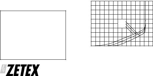
|
10 |
|
|
|
|
|
|
|
A) |
8 |
|
|
|
|
|
|
|
( |
|
|
|
|
|
|
|
|
Current |
6 |
|
|
|
|
|
|
|
|
|
|
-40°C |
|
|
|
|
|
|
|
|
25°C |
|
|
|
|
|
Reverse |
|
|
|
|
|
|
|
|
4 |
|
|
85°C |
|
|
|
|
|
|
|
|
|
|
|
|
||
2 |
|
|
|
|
|
|
|
|
|
0 |
|
|
|
|
|
|
|
|
0 |
0.2 |
0.4 |
0.6 |
0.8 |
1.0 |
1.2 |
1.4 |
Reverse Voltage (V)
Reverse Characteristics
ISSUE 2 - JUNE 1999
2
 Loading...