


EnergyMetering
multipulse, multilog
Installation and operating manual
Electronic pulse counter module with 3 inputs for connection
of meters with pulse outputs
All that counts.

General information
With multipulse resp. multilog you have acquired one of the most up-to-date and modern electronic pulse counter modules currently available on the market.
Expressive symbols in the display and easy menu navigation make readout simple. It can be operated with one single button. The change of pulse values and the setting of the data loggers with multilog is being done via the software GMM. The pulse counter module is equipped with a longlife battery made for operation during a period of 5 years including a reserve of at least another year. With a second battery you will reach 11 years.
Electro-magnetic interference
multipulse resp. multilog fulfils the national and international requirements for interference resistance. To avoid malfunctions due to other interferences, do not install fluorescent lamps, switch cabinets or electric devices such as motors or pumps in the immediate vicinity of the meter (minimum distance 1 m). Cables leaving the meter should not be laid parallel to live cables (230V, minimum distance 0.2 m).
Cables leaving the meter should not be laid parallel to live cables (230V, minimum distance 0.2 m). The device complies with Directive 89/336/EEC (electromagnetic compatibility).
Care instructions
Clean plastic surfaces with a damp cloth only. Do not use any scouring or aggressive cleaning agents! The device is maintenance-free during the service life. Repairs can only be made by the manufacturer. The most up-to-date information about this product and of our installation notice can be found at www.zenner.com.
2
|
|
|
|
|
|
|
|
|
|
|
|
|
Technical data |
|
|
|
|
|
|
|
Dispay |
Multifunctional LCD, 8-digit, floating |
|
|
|
|
|
|
Interface meter |
Models with contact pulsers or active pulsers (no |
|
|
|
Namur or Opto) Reed max. 1Hz /active max. 100 Hz |
|
|
|
|
|
|
Interfaces |
optical, optionally ZR-Bus, M-Bus, RS-232, |
|
|
|
|
|
|
Ambient temperature |
°C 0 - 55 |
|
|
Power supply |
Battery 3.6 V Lithium, |
|
|
|
optionally mains power supply 230V/24V |
|
|
|
|
|
|
Battery lifetime |
6 years, optionally 11 years |
|
|
Protection class |
IP 54 / IP 65, acc. to DIN 40050 |
|
|
|
|
|
|
Mechanical/electro-magnetic class |
M1/E1 |
|
|
|
|
|
|
Technical data flow sensor input |
|
|
|
|
|
|
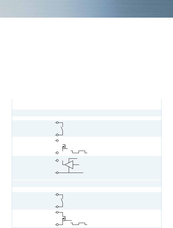
Flow sensor input
Electrical connection Schematic diagram
Passive with |
10 |
|
|
|
|
|
|
|
|
|
|
mechanical |
|
|
|
|
|
|
|
|
|
|
|
contact (Reed) |
11 |
|
|
|
|
|
|
|
|
|
|
Passive with |
10 |
|
|
|
|
|
|
|
|
|
|
|
|
|
|
|
|
|
|
|
|
||
open drain FET |
|
|
|
|
|
|
|
|
|
|
|
|
|
|
pulse |
||||||||
Active f.ex. with |
11 |
|
|
|
VCC 2,5 … 3,6 V |
||||||
|
|
|
|||||||||
|
|
|
|||||||||
|
|
|
|
||||||||
C-MOS Gate |
10 |
|
|
|
|
|
|
|
pulse |
||
|
|
|
|
|
|
|
|
|
|
|
|
|
Uhigh = 2,5 … 3,6 V |
|
|
|
|
|
|
||||
|
Ulow = 0 … 0,3 V |
|
|
|
|
|
|||||
|
11 |
|
|
|
|
|
|
|
|
|
|
|
|
|
|
|
|
|
|
GND |
|||
Connection data
1 Hz Version: fmax = 1 Hz, Pulse-duty factor 1:1 to 1:9 Input capacitance: approx. 10 nF, Input resistance approx 850 kOhm
100 Hz Version: not allowed
1 Hz Version: fmax = 1 Hz, Pulse-duty factor 1:1 to 1:9 Input capacitance: approx. 10 nF, Input resistance approx 850 kOhm 100 Hz Version: fmax = 30 Hz, Pulse-duty factor 1:1, Input capacitance: approx. 2,5 nF, Input resistance approx. 850 kOhm
1 Hz Version: fmax = 1 Hz, Pulse-duty factor 1:1 to 1:9 Uhigh = 2,5 … 3,6V, Ulow = 0 … 0,3 V, Input capacitance: approx. 10 nF, Input resistance approx 850 kOhm
100 Hz Version: fmax = 100 Hz, Pulse-duty factor 1:1 Uhigh = 2,5 … 3,6V, Ulow = 0 … 0,3 V, Input capacitance: approx. 2,5 nF, Input resistance approx. 850 kOhm
Technical data additional inputs
Electrical connection Schematic diagram
Passive with |
52/ |
|
mechanical |
54 |
|
55 |
||
contact (Reed) |
||
|
53/ |
|
Passive with |
52/ |
|
open drain FET |
54 |
|
pulse |
||
|
53/ |
|
|
55 |
Connection data
fmax = 1 Hz,
Pulse-duty factor 1:1 to 1:9 Input capacitance: approx. 15 nF,
Input resistance approx 470 kOhm
fmax = 1 Hz,
Pulse-duty factor 1:1 to 1:9 Input capacitance: approx. 15 nF,
Input resistance approx 470 kOhm
3
Connector pin assignment |
|
|
|
Main input |
|
|
|
Volume pulse |
10 |
Volume GND |
11 |
|
|
Additional inputs |
|
Input 1 pulse |
52 |
|
|
Input 1 GND |
53 |
Input 2 pulse |
54 |
|
|
Input 2 GND |
55 |
M-Bus |
|
|
|
M-Bus A |
24 |
M-Bus B |
25 |
|
|
RS-232 |
|
DTR |
71 |
|
|
GND |
72 |
Tx |
73 |
|
|
Rx |
74 |
RS-485 |
|
+UB |
71 |
GND |
72 |
|
|
A |
73 |
B |
74 |
|
|
Note
You can download additional information in our product area at www.zenner.com.

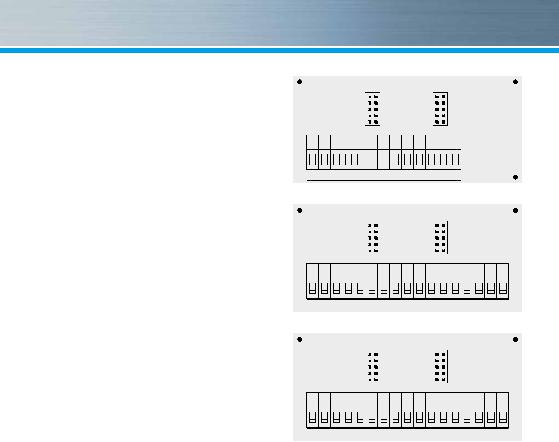
 1
1  2
2  3
3  4
4  10
10 11
11 9
9  50
50 51
51 52
52 53
53 54
54 55
55
Version without interface

 1
1  2
2  3
3  4
4  10
10 11
11 9
9  50
50 51
51 52
52 53
53 54
54 55
55 24
24 25
25 24
24 25
25
 Version M-Bus

 1
1  2
2  3
3  4
4  10
10 11
11 9
9  50
50 51
51 52
52 53
53 54
54 55
55 71
71 72
72 73
73 74
74
 Version RS 232 / RS 485 (ZR-Bus)
If water meters with a potential free reed contact are connected to the inputs the connection can be made in any direction.
The connectors are given twice for the incoming and outgoing of the M-bus wires.
Depending on the pulse counter module’s model the version of the connection board can differ.
4
 Loading...