


EnergieMetering
zelsius® C5-IUF
Installation and operating manual
Electronic compact heat meter with ultrasonic flow sensor IUF
optionally M-Bus, wM-Bus and 3 inputs/outputs optional qp 0,6/1,5/2,5 m3/h
All that counts.

Installation manual
General information
With zelsius C5 IUF, you have acquired one of the most up-to-date, modern heat meters currently available on the market. By this version, the water volume is determined based on the transit time method. The measurement accuracy is based on the measurement requirements of EN 1434 class 2, optionally class 3. Expressive
symbols in the display and easy menu navigation make readout simple. Can be operated with one single button. It is equipped with a long-life battery made for operation during the initial verification validity period (5 years) including a reserve of at least another year. The meter can be equipped optionally with a battery lifetime of 11 years.
Technical data flow sensor IUF
Nominal flow qp |
m³/h |
0,6 |
1,5 |
|
2,5 |
|
Maximum flow qs |
m³/h |
1,2 |
3 |
|
5 |
|
Minimum flow qi |
l / h |
6 / 12 / 24 |
15 / 30 / 60 |
|
25 / 50 / 100 |
|
Pressure loss at qp |
bar |
|
|
<= 0,25 bar |
|
|
Medium temperature range |
°C |
|
0°C <= Ɵ q <= 90°C / 0°C <= Ɵ q <= 130°C |
|||
Minimum pressure (to avoid cavitation) |
bar |
|
1 bar at qp and 80°C medium temperature range |
|||
Measurement accuracy class |
|
|
|
3 / 2 |
|
|
Nominal pressure/peak pressure |
PS/PN |
|
Body with |
|
16/16 |
|
|
|
|||||
|
threaded connection |
|
||||
|
|
|
|
|
||
|
PS/PN |
|
Body with flange/DN |
|
16/16 / 25/25 |
|
IP-Protection class |
|
|
|
68 |
|
|
Installation position |
|
|
|
in any position |
|
|
Installation |
|
|
return flow optionally forward flow |
|||
Cable length up to calculator |
m |
|
|
1,2 |
|
|
Installation place temperature sensorsd |
|
|
|
M10 x 1 |
|
|
Heat carrier (Medium) |
|
|
|
Water |
|
|
Nominal diameter |
DN |
|
15 |
|
|
|
|
15 |
|
20 |
|||
Connecting threads* |
Nominal flow qp |
|
L [mm] |
Threaded |
|
Flange / ND |
|
(m³/h) |
|
connection |
|
||
|
|
|
|
|
||
|
0,6 |
|
110 |
G¾B |
|
-- |
|
0,6 |
|
130 |
G1B |
|
-- |
|
0,6 |
|
190 |
G1B |
|
20 |
|
1,5 |
|
110 |
G¾B |
|
-- |
|
1,5 |
|
130 |
G1B |
|
-- |
|
1,5 |
|
190 |
G1B |
|
20 |
|
2,5 |
|
130 |
G1B |
|
-- |
|
2,5 |
|
190 |
G1B |
|
20 |
|
|
|
|
|
|
|
* optionally |
|
|
|
|
|
|
2

MID - Initial verification
zelsius® C5-IUF is produced and tested in compliance with the new European Measuring Instruments Directive (MID). According to this directive, devices are no longer carrying an ini-
tial verification stamp, but rather the year of the device’s declaration of conformity (recognizable on the front of the device, for example: M12). The MID controls the use of heat meters up to the moment they are placed on the market resp.
Technical data calculator
Temperature range |
°C |
|
0...105 / 0...150 * |
Temperature difference range |
K |
|
3...80 / 3...130 * |
Display |
|
|
LCD 8-stellig + Sonderzeichen |
Ambient temperature during operation |
°C |
|
5...55 |
Storage temperature |
°C |
|
-20...+65 |
Resolution temperature |
°C |
|
0,01 |
Measurement frequency |
s |
adjustable ex works, beginning with 2s, standard 32s |
|
Unit to read the heat consumption |
|
|
Standard MWh; optionally kWh, GJ |
Data storage |
|
|
1 x daily |
Due date values |
|
Storage of all monthly values during the entire operation time |
|
Maximum value storage |
|
extensive storage of flow rate, performance and other parameters |
|
Interface |
Standard |
Optical interface (ZVEI, IrDA), 3 Pulseinputs/-outputs |
|
|
optional |
|
M-Bus, wM-Bus, RS485, radio |
Supply |
|
|
3,6 V lithium battery (different capacities) |
Battery lifetime |
Years |
> 6, opt. > 11 (changeable during the operation time) |
|
Protection class |
|
|
IP54 |
EMC |
|
|
A |
|
- climatic |
|
Highest permissible ambient temperature 55°C, |
Ambient conditions/climatic |
|
Lowest permissible ambient temperature 5°C, |
|
|
|
Humidity class IP54 |
|
influencing (valid for complete |
|
|
|
compact meter) |
- mechanical class |
M1 |
|
|
- electro-magnetic class |
E1 |
|
Technical data temperature sensors
Platinum precision resistor |
|
Sensor diameter type |
mm |
Temperature range |
°C |
Cable length |
m |
|
VL |
Installation |
RL |
|
Pt 1000
45 x 5,0 mm / 45 x 5,2 mm / DS 27,5 more on request 0 – 105/0…150
1,5 (opt. 5)
by direct immersion or by immersion sleeves (in case of existing measuring points)
by direct immersion or by immersion sleeves (in case of existing measuring points) Integrated in the flow sensor, optionally external
Dimensioning limits may apply for non-symetrical temperature sensors installation. * optionally
3
their first putting into use. After this, the national regulations for devices subject to compulsory verification apply within the EU. The duration of initial verification validity in Germany remains 5 years for heat meters.
After this period has expired the measuring device may no longer be used for billing in commercial use. The regulations resp. validity period may vary in other countries of the EU. ZENNER International GmbH & Co. KG declares that this product with the number of the EC type-exam- ination certificate DE-12-MI004-PTB010 complies with the requirements of the EC directives 2004/22/EC (Measuring instruments directive) and 89/336/EEC (electro-magnetic compatibility)
Electro-magnetic interference
zelsius® C5-IUF fulfils the national and international requirements for interference resistance. To avoid malfunctions due to other interferences, do not install fluorescent lamps, switch cabinets or electric devices such as motors or pumps in the immediate vicinity of the meter. Cables leaving the meter should not be laid parallel to live cables (230V) (minimum distance 0.2m)/
Care instructions
Clean plastic surfaces with a damp cloth only. Do not use any scouring or aggressive cleaning agents!
The device is maintenance-free during the service life. Repairs can only be made by the manufacturer. The most up-to-date information about this product nd of our installation notice can be found at www.zenner.com.
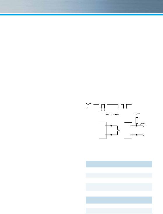
Pulse inputs and outputs
(optional)
By meters with pulse outputs, the pulse value can be called up in the display (see the display overview, Level 4). The pulse value of the outputs is permanently set and corresponds with the last position of the associated display value.
Example:
Output 1 = energy output
Energy display = XXXXX.XXX
Last position = 0.001 MWh = 1 kWh
Output pulse = 1 kWh
In 1…3 |
Out 1…3 |
GND |
GND |
Input |
Output |
colour |
connection |
signification |
|
|
|
|
|
white |
I/O 1 |
In-/Output 1 |
|
yellow |
I/O 2 |
In-/Output 2 |
|
green |
I/O 3 |
In-/Output 3 |
|
brown |
GND |
common ground for |
|
I/O 1-3 |
|||
|
|
Technical data M-Bus
Cable length |
1,5 m |
Cable |
D=3,8 mm, 2-core |
4
 Loading...