


EnergyMetering
zelsius® C5-ISF
Installation and operating manual
electronic compact heat meter with single-jet flow sensor ISF
M-Bus, wM-Bus and 3 inputs/outputs optional qp 0,6/1,5/2,5 m3/h
All that counts.

Installation manual
General information
With zelsius® C5-ISF you have acquired one of the most up-to-date, modern heat meters currently available on the market.
Expressive symbols in the display and easy menu navigation make readout simple. Can be operated with one single button. It is equipped with a long-life battery made for operation during the initial verification validity period (5 years) including a reserve of at least another year. The meter can be equipped optionally with a battery lifetime of 11 years.
MID - Initial verification
zelsius® C5-ISF is produced and tested in compliance with the new European Measur-
ing Instruments Directive (MID). According to this directive, devices are no longer carrying an initial verification stamp, but rather the year of the device’s declaration of conformity (recognizable on the front of the device, for example:
M12). The MID controls the use of heat meters up to the moment they are placed on the market resp. their first putting into use. After this, the national regulations for devices subject to compulsory verification apply within the EU.
The duration of initial verification validity in Germany remains 5 years for heat meters. After this period has expired the measuring device may no longer be used for billing in commercial use.
The regulations resp. validity period may vary in other countries of the EU.
Technical data flow sensor ISF
Nominal flow qp |
|
m³/h |
0,6 |
|
1,5 |
|
2,5 |
Maximum flow qs |
|
m³/h |
1,2 |
|
3,0 |
|
5,0 |
Minimum flow qi |
horizontally* |
l / h |
12 / 24 |
|
30 / 60 |
|
50 / 100 |
Minimum flow qi |
vertically* |
l / h |
12 / 24 |
|
30 / 60 |
|
50 / 100 |
Starting flow horizontally ca. |
l/h |
4 |
|
4 |
|
5 |
|
Pressure loss at qp |
bar |
|
|
<= 0,25 bar |
|
||
Temperature range |
°C |
|
|
10°C <= θq <= 90°C |
|
||
Minimum pressure |
bar |
|
0,3 |
|
|
||
(to avoid cavitation) |
|
|
|
|
|||
|
|
|
|
|
|
|
|
Measurement accuracy class |
|
|
3 |
|
|
||
Nominal pressure |
PS/PN |
|
16 |
|
|
||
Nominal diameter |
DN |
15 |
|
|
|
20 |
|
|
15 |
|
|||||
Installation position |
|
horizontally or vertically, no upside down installation |
|||||
Installation |
|
|
|
return flow optionally forward flow |
|
||
Cable length up to calculator |
m |
|
1,2 |
|
|
||
(in version combi) |
|
|
|
|
|||
|
|
|
|
|
|
|
|
Installation place temperature sensors |
|
|
|
M10 x 1 |
|
||
Heat carrier (Medium) |
|
|
|
water |
|
||
* Standard: Ratio 25; optionally R50 but not for qp=0,6 and non-symmetrical temperature sensors installation
2
ZENNER International GmbH & Co. KG declares that this product with the number of the EC typeexamination certificate DE-12-MI004-PTB010 complies with the requirements of the EC directives 2004/22/EC (Measuring instruments directive) and 89/336/ EEC (electro-magnetic compatibility).
Electro-magnetic interference
zelsius® C5-ISF fulfils the national and international requirements for interference resistance. To avoid malfunctions due to other interferences, do not install fluorescent lamps, switch cabinets or electric devices such as motors or pumps in the immediate vicinity of the meter
(minimum distance 1 m). Cables leaving the meter should not be laid parallel to live cables
(230V) (minimum distance 0.2 m).
Care instructions
Clean plastic surfaces with a damp cloth only. Do not use any scouring or aggressive cleaning agents! The device is maintenance-free during the service life. Repairs can only be made by the manufacturer.
The most up-to-date information about this product and of our installation notice can be found at www.zenner.com.
Pulse inputs and outputs (optional)
By meters with pulse outputs, the pulse value can be called up in the display (see the display overview, Level 4).
The pulse value of the outputs is permanently set and corresponds with the last position of the associated display value.
Example:
Output 1 = energy output
Energy display = XXXXX.XXX
Last position = 0.001 MWh = 1 kWh
Output pulse = 1 kWh
In 1…3 |
Out 1…3 |
GND |
GND |
Eingang |
Ausgang |
Technical data temperature sensors
Platinum resistance |
|
Pt 1000 |
|
Sensor diameter/type |
mm |
Standard: 5,0 (DS according to EN 1434); other sizes on demand |
|
Temperature range |
°C |
0 - 105 |
|
Cable length |
m |
1,5 (opt. 5) |
|
|
forward |
by direct immersion or by immersion sleeves (in case of existing measuring points ) |
|
|
temp.-sensor |
||
Installation |
|
||
return |
by direct immersion or by immersion sleeves (in case of existing measuring points); |
||
|
|||
|
temp.-sensor |
optionally integrated in flow sensor |
3

Technical data calculator
Temperature range |
°C |
0…105 |
|
Temperature difference range |
K |
3…80 |
|
Display |
|
LCD 8-digit + additional character |
|
Ambient temperature |
°C |
5...55 |
|
Minimum temperature diffence |
K |
3 ( cooling or change-over: 2) |
|
Resolution temperature |
°C |
0,01 |
|
Measurement frequency |
s |
adjustable ex works, beginning with 2s, standard 30s |
|
Unit to read the heat consumption |
|
Standard MWh; optionally kWh, GJ |
|
Data storage |
|
1 x daily |
|
Due date values |
|
Storage of all monthly values during the entire operating time |
|
Maximum value storage |
|
extensive storage of flow rate, performance and other parameters |
|
Interface |
Standard |
optical interface (ZVEI, IrDA) |
|
|
optional |
M-Bus, wM-Bus, RS485, radio |
|
Supply |
|
3,6 V lithium battery (different capacities) |
|
Battery lifetime |
Years |
> 6, opt. > 11 (changeable during the operation time) |
|
Protection class |
|
IP54 |
|
EMC |
|
C |
|
|
- climatic |
Highest permissible ambient temperature 55°C |
|
Ambient conditions / |
Lowest permissible ambient temperature 5°C |
||
|
Humidity class IP54 |
||
climatic influencing |
- mechanical |
M1 |
|
(valid for complete |
|||
class |
|||
compact meter) |
|
||
- electro-magnetic |
|
||
|
E1 |
||
|
class |
||
|
|
colour |
connection |
signification |
|
|
|
|
|
white |
I/O 1 |
In-/Output 1 |
|
yellow |
I/O 2 |
In-/Output 2 |
|
green |
I/O 3 |
In-/Output 3 |
|
brown |
GND |
common ground for |
|
I/O 1-3 |
|||
|
|
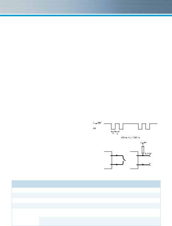
Technical data I/O
Load max. |
max. 30V DC/20 mA |
I/O 1, 2, 3 |
Open Drain, n-channel FET |
Cable |
D = 3.8 mm, 4-core |
Pulse-duty factor |
1:1 (out); 1:5 (in) |
Cable length |
1,5 m |
Input frequency |
max. 1 Hz |
Technical data M-Bus |
|
|
|
|
|
|
|
Cable length |
1,5 m |
A firmly attached cable is included: external |
|
Cable |
D=3.8 mm, 2-core |
||
wiring must be done by oneself. |
|||
|
|
4
 Loading...