

Page 1
EnergyMetering
multipulse, multilog
Installation and
operating manual
Electronic pulse counter module
with 3 inputs for connection
of meters
with pulse outputs
All that counts.
Page 2

General information
With multipulse resp. multilog you have acquired
one of the most up-to-date and modern electron-
ic pulse counter modules currently available on
the market.
Expressive symbols in the display and easy
menu navigation make readout simple. It can be
operated with one single button. The change of
pulse values and the setting of the data loggers
with multilog is being done via the software GMM.
The pulse counter module is equipped with a long-
life battery made for operation during a period of 5
years including a reserve of at least another year.
With a second battery you will reach 11 years.
Electro-magnetic interference
multipulse resp. multilog fulls the national and
international requirements for interference resis-
tance. To avoid malfunctions due to other inter-
ferences, do not install uorescent lamps, switch
cabinets or electric devices such as motors or
pumps in the immediate vicinity of the meter
(minimum distance 1 m). Cables leaving the
meter should not be laid parallel to live cables
(230V, minimum distance 0.2 m).
Care instructions
Clean plastic surfaces with a damp cloth only.
Do not use any scouring or aggressive cleaning
agents! The device is maintenance-free during
the service life. Repairs can only be made by the
manufacturer. The most up-to-date information
about this product and of our installation notice
can be found at www.zenner.com.
Cables leaving the meter should not be laid paral-
lel to live cables (230V, minimum distance 0.2 m).
The device complies with Directive 89/336/EEC
(electromagnetic compatibility).
2
Page 3
11
10
GND
pulse
11
10
pulse
11
10
VCC 2,5 … 3,6 V
Uhigh = 2,5 … 3,6 V
Ulow = 0 … 0,3 V
11
10
52/
54
11
10
GND
pulse
11
10
pulse
11
10
VCC 2,5 … 3,6 V
53/
55
Uhigh = 2,5 … 3,6 V
Ulow = 0 … 0,3 V
11
10
pulse
11
10
Technical data
Dispay Multifunctional LCD, 8-digit, oating
Interface meter Models with contact pulsers or active pulsers (no
Namur or Opto) Reed max. 1Hz /active max. 100 Hz
Interfaces optical, optionally ZR-Bus, M-Bus, RS-232,
Ambient temperature °C 0 - 55
Power supply Battery 3.6 V Lithium,
optionally mains power supply 230V/24V
Battery lifetime 6 years, optionally 11 years
Protection class IP 54 / IP 65, acc. to DIN 40050
Mechanical/electro-magnetic class
M1/E1
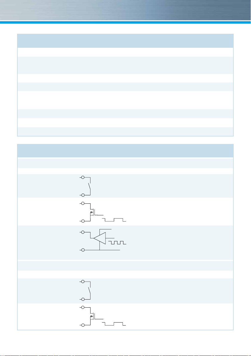
Technical data flow sensor input
Flow sensor input
Electrical connection Schematic diagram Connection data
Passive with
10
mechanical
contact (Reed)
Passive with
open drain FET
Active f.ex. with
C-MOS Gate
Technical data additional inputs
Electrical connection Schematic diagram Connection data
Passive with
mechanical
contact (Reed)
Passive with
open drain FET
11
10
11
10
Uhigh = 2,5 … 3,6 V
Ulow = 0 … 0,3 V
11
52/
54
53/
55
52/
54
53/
55
pulse
VCC 2,5 … 3,6 V
pulse
1 Hz Version: fmax = 1 Hz, Pulse-duty factor 1:1 to 1:9 Input
capacitance: approx. 10 nF, Input resistance approx 850 kOhm
100 Hz Version: not allowed
1 Hz Version: fmax = 1 Hz, Pulse-duty factor 1:1 to 1:9 Input
capacitance: approx. 10 nF, Input resistance approx 850 kOhm
100 Hz Version: fmax = 30 Hz, Pulse-duty factor 1:1, Input
capacitance: approx. 2,5 nF, Input resistance approx. 850 kOhm
1 Hz Version: fmax = 1 Hz, Pulse-duty factor 1:1 to 1:9
Uhigh = 2,5 … 3,6V, Ulow = 0 … 0,3 V, Input capacitance:
pulse
approx. 10 nF, Input resistance approx 850 kOhm
100 Hz Version: fmax = 100 Hz, Pulse-duty factor 1:1
Uhigh = 2,5 … 3,6V, Ulow = 0 … 0,3 V, Input capacitance:
GND
approx. 2,5 nF, Input resistance approx. 850 kOhm
fmax = 1 Hz,
Pulse-duty factor 1:1 to 1:9
Input capacitance: approx. 15 nF,
Input resistance approx 470 kOhm
fmax = 1 Hz,
Pulse-duty factor 1:1 to 1:9
Input capacitance: approx. 15 nF,
Input resistance approx 470 kOhm
3
Page 4
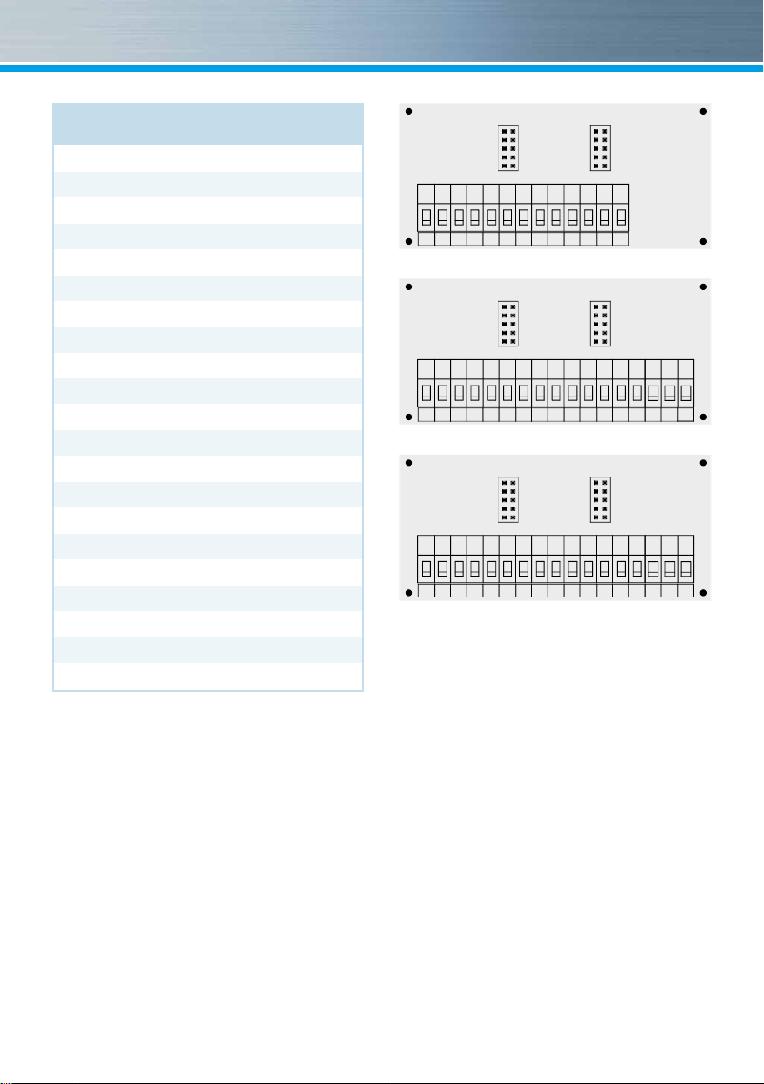
Connector pin assignment
Main input
Volume pulse 10
Volume GND 11
Additional inputs
Input 1 pulse 52
Input 1 GND 53
Input 2 pulse 54
Input 2 GND 55
M-Bus
M-Bus A 24
M-Bus B 25
RS-232
DTR 71
GND 72
Tx 73
Rx 74
RS-485
+UB 71
GND 72
A 73
B 74
Note
You can download additional information in our
product area at www.zenner.com.
1 2 3 4 10 11 9 50 51 52 53 54 55
Version without interface
1 2 3 4 10 11 9 50 51 52 53 54 55 24 25 24 25
Version M-Bus
1 2 3 4 10 11 9 50 51 52 53 54 55 71 72 73 74
Version RS 232 / RS 485 (ZR-Bus)
If water meters with a potential free reed contact
are connected to the inputs the connection can
be made in any direction.
The connectors are given twice for the incoming
and outgoing of the M-bus wires.
Depending on the pulse counter module’s model
the version of the connection board can differ.
4
Page 5

Communication
The pulse values can be programmed via the
software GMM. The pulse value can be called up
in the display (see the display overview, Level 1).
The display resolution should be chosen in such
way that the display can not overow within one
years time.
M-Bus (optional)
The optional M-Bus interface complies with the
norm EN 1434-3 and operates with 2400 baud
xed. It can be set to 300/9600 baud if neces-
sary.
B
Dimensions
Height: H = 106 mm
Width: B = 126 mm
Depth: T = 54 mm
H
T
5
Page 6

Installation instructions
Safety instructions
The installation has to be done by qualied per-
sonnel. Read the instructions carefully right up to
the end before starting to mount the device.
The current laws and regulations regarding the
installation have to be observed
At devices with communication interfaces or
mains supply the general technical rules and the
correspondent regulations have to be followed.
General Information
Take care of:
■ the display of the module must readable at all
times,
■ to avoid malfunctions due to other interfer-
ences do not install uorescent lamps, switch
cabinets or electric devices such as motors or
pumps in the immediate vicinity of the module
(minimum distance 1 m),
■ the ambient temperature must not exceed
55°C,
■ the pulse value of the meter must correspond
with the one from the module.
The module has 7 cable glands for wires with a
diameter between 4,2 and 10 mm. Keep unused
glands closed. multipulse resp. multilog is deliv-
ered ready for operation. It does not need any set-
tings or adjusting.
ZENNER International GmbH & Co. KG
Römerstadt 6
D-66121 Saarbrücken
Telephone +49 681 99 676-30
Telefax +49 681 99 676-3100
E-Mail info@zenner.com
Internet www.zenner.com
Subject to modications and errors excepted. Any liability for misprints excluded. SAP124288_150601_EN
6
Page 7

Installation pulse counting module
ZENNER recommends to mount the module on
the wall.
Do not mount the device at the pipe or attach it
directly on the meter. The mounting adapter at
the backside of the module can be used for rail
mounting or for wall mounting.
For wall mounting detach the adapter and turn it
180°, attach the adapter with at least two screws
to the wall and clip the module on it.
For rail mounting lift the adapter a little bit, place
the module on the rail and push the adapter
back until it locks.
Connection meter
With mechanical meters the connection order is
optional. Mind the polarity at electronic meters.
External power supply
A small vertical line appears in the display when
the optional external power supply is on service.
In case of a failure of the external power sup-
ply the devices switches automatically to battery
supply.
The battery lifetime can be checked in the dis-
play (level 3). After having reached the date the
battery has to be replaced if needed.
Rail mounting Wall mounting
7
Page 8

Operation test
Check the pulse counter module for any error
codes in the display after installation (see table
for error codes).
Most of the errors can be deleted by pressing
the button. If the error appears permanently, it
will be detected at the next measuring cycle and
displayed again.
When attaching the top cover on the housing
pulses on the inputs can possibly be generated.
Check readings of the inputs and correct if nec-
essary.
Sealing
We recommend sealing the device with the in-
cluded seals to prevent unauthorized opening.
Maintenance
Repairs or overhaul are only allowed by the
manufacturer or companies authorized by the
manufacturer.
8
Page 9

Status display / Error codes
The symbols in the table below show the pulse counting module’s operational status. The status
mes
sages only appear in the main display! The temporary display of the warning triangle can be caused
by special operating states and does not always mean that the device is malfunctioning. However,
should the symbol be displayed over a longer period of time you should contact the service company.
Symbol Status Event
Flow existent -
Data transmission -
Emergency operation Exchange device
External power supply -
Error codes show faults detected by multipulse resp. multilog. If more than one error appears, the sum of
the error codes is displayed: Error 1100 = error 1000 and error 100.
Code Error Event
100 Emergency operation Exchange device
1000 Battery life time exceeded Exchange device
> 8000 Internal hardware error Exchange device
9
Page 10

Level 1 Level 2
Monthly value main input
Monthly value input 1
Monthly value input 2
Pulse value main input
Basic configuration
Model number
Date battery end
Time
Date
M-bus address
Baud rate
Input display
Remaining energy read-out
Date SRD
SRD value input 1
SRD value input 2
Monthly values main input Date month main input Monthly value main input
Date month input 1
Date month input 2
Monthly value input 1
Monthly value input 2
Monthly values input 1
Monthly values input 2
Serial number
Customer number
Serial number input 1
Serial number input 2
Main input volume at SRD
Date SRD
Main input volume at SRD
You can switch levels at
any point in the menu.
H
Volume main input
Volume input 1
Volume input 2
Segment test
Flow
S
L
L
H
Pulse value main input
H
Pulse value input 2
SRD value input 1
SRD value input 2
L
Monthly values main input Date month main input
L
Monthly values input 1
L
Monthly values input 2
Serial number
Customer number
Serial number input 1
Serial number input 2
Monthly consumption
H
H
Date month input 1
H
Date month input 2
L
L
L
S
10
Page 11

S
Kälte am Stichtag
Monatswerte Kälte
Fühlerart und Einbauort
Monthly value main input
S
Monthly value input 1
S
Monthly value input 2
Level 3
Pulse value main input
Basic configuration
Model number
Date battery end
Time
Date
M-bus address
Baud rate
Remaining energy read-out
Input display
Error status
H
S
L
H
Legend
Press the button briey (S),
to switch through the display
from top to bottom. When hav-
ing reached the last menu item
the device automatically jumps
back to the menu item at the
top (loop).
Press the button for about 2
seconds (L), wait for the door
symbol to appear (upper right
corner of the display) and then
release the button.
The menu is then updated
resp. switches to the sub-
menu.
Hold down the button (H) until
the device switches to another
level or switches back from the
sub-menu.
Note
Depending on your mulipulse
or multilog model its displays
can differ in number and order
from those shown here.
Software version
S
11
Page 12

Disposal
Attention: This device contains a non-remova-
ble and non-rechargeable lithium battery.
Batteries contain substances, which could harm
the environment and might endanger human
health if not disposed of properly.
To reduce the disposal quantity so as unavoid-
able pollutants from electrical and electronic
equipment in waste, old equipment should be
reused prior or materials recycled or reused as
another form.
This is only possible if old equipment, which con-
tains batteries or other accessories are disposed.
Therefore please contact the department of your
local authority which is responsible for waste
disposal. Alternatively a waste disposal via
ZENNER is possible.
Your local or municipal authority or the local
waste disposal company can give you informa-
tion relating the collection points for your used
equipments.
Attention:
Do not dispose of the devices with domestic
waste.
In this way, you will help to protect natural re-
sources and to promote the sustainable reuse
of material resources.
For any question, please contact
info@zenner.com
The most up-to-date information about this prod-
uct and of our installation notice can be found at
www.zenner.com
12
 Loading...