

Page 1
EnergyMetering
multidata
Installation and operating manual
Electronic energy calculator for heat meters
with 2 inputs/outputs
optionally with M-Bus, RS-232 and RS-485
All that counts.
Page 2

General information
With multidata you have acquired one of the
most up-to-date, modern heat calculators cur-
rently available on the market.
Expressive symbols in the display and easy
menu navigation make readout simple. It can be
operated with one single button. The setting of
the data loggers (depending on the type of de-
vice) is being done via the software GMM.
The calculator is equipped with a long-life battery
made for operation during the initial verication
validity period (5 years) including a reserve of at
least another year. With a second battery you will
reach 11 years.
Initial verification
multidata is produced and tested in compliance
with the new European measuring instruments
directive (MID). According to this directive, de-
vices do no longer carry an initial verication
stamp, but rather the year of the device’s decla-
ration of conformity (recognizable on the front of
the device, for example: M09). The MID controls
the use of heat meters up to the moment they
are placed on the market resp. their rst putting
into use. After this, the national regulations for
devices subject to legal verication apply within
the EU.
Technical data multidata
Temperature range
Temperaturdifferenz k 3 - 120
Display Multifunctional LCD, 8-digit, oating
Display unit
Interface ow sensor
Temperature sensor connection
Max. cable length 2-wire
Max. cable length 4-wire
Interfaces
Ambient temperature
Power supply
Battery lifetime
Protection class IP 54 / IP 65, acc. to DIN 40050
Mechanical/electro-magnetic class
Accuracy class according to EN1434
Measuring cycle dynamic
°C 1 - 150
MWh, kWh, GJ, MJ
Models with contact pulsers or active pulser
(no Namur or Opto),
passive max. 1Hz / active max. 100 Hz
PT500, optional PT100, PT1000
12,5 m (PT500), 2,5 m (PT100), 20 m (PT1000)
20 m
optical, optionally ZR-Bus (RS-485), M-Bus, RS-232,
remote readout outputs
°C 5 - 55
Battery 3.6 V Lithium,
optionally mains power supply 230V/24V
6 years, optionally 11 years
M1/E1
40s/30s/10s
2
Page 3
11
10
GND
pulse
11
10
pulse
11
10
VCC 2,5 … 3,6 V
Uhigh = 2,5 … 3,6 V
Ulow = 0 … 0,3 V
11
10
52/
54
11
10
GND
pulse
11
10
pulse
11
10
VCC 2,5 … 3,6 V
53/
55
Uhigh = 2,5 … 3,6 V
Ulow = 0 … 0,3 V
11
10
pulse
11
10
pulse
GND
pulse
pulse
VCC 2,5 … 3,6 V
pulse
52/
54
11
10
GND
pulse
11
10
pulse
11
10
VCC 2,5 … 3,6 V
tp
tp
53/
55
52/
54
53/
55
Uhigh = 2,5 … 3,6 V
Ulow = 0 … 0,3 V
pulse
52/
54
11
10
GND
pulse
11
10
pulse
11
10
VCC 2,5 … 3,6 V
U = 3 … 30 V
Imax = 20 mA
tp
tp
53/
55
52/
54
53/
55
52/
54
Uhigh = 2,5 … 3,6 V
Ulow = 0 … 0,3 V
The duration of initial verication validity in Germany
remains 5 years for heat meters. After this period has
expired, the measuring device may no longer be used
for billing in commercial use. The regulations resp.
validity period may vary in other countries of the EU.
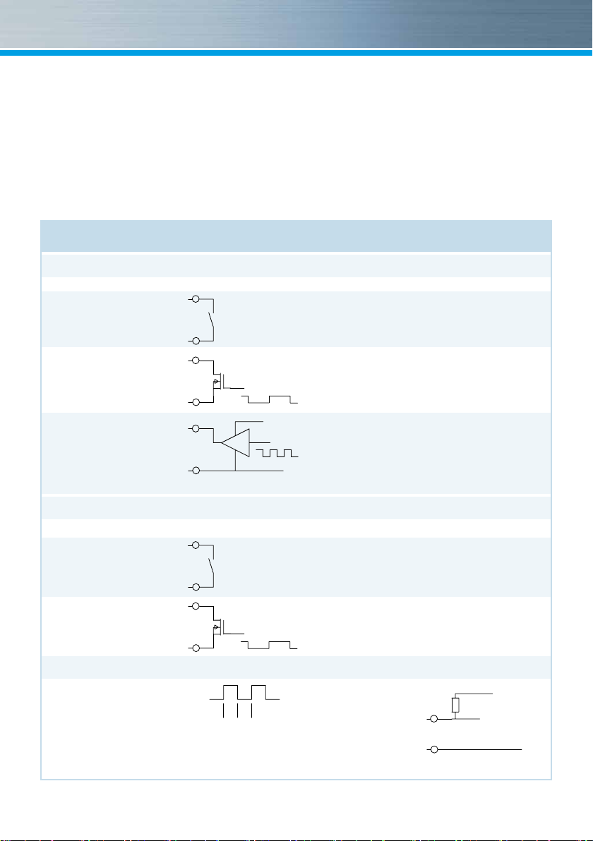
Technical data flow sensor input
Flow sensor input
Electrical connection Schematic diagram Connection data
Passive with
10
mechanical
contact (Reed)
Passive with
open drain FET
Active f.ex. with
C-MOS Gate
Technical data additional inputs
Electrical connection Schematic diagram Connection data
Passive with
mechanical
contact (Reed)
Passive with
open drain FET
Connection data outputs
Ext. Voltage 3V … 30 V DC
Max. current 20 mA
Output frequency 1 Hz (8 Hz dynamically switching, if output
with 1 Hz is not possible)
Switching times: 1 Hz: 400ms < tp < 600 ms
8 Hz: 50ms < tp < 80 ms
11
10
11
10
Uhigh = 2,5 … 3,6 V
Ulow = 0 … 0,3 V
11
52/
54
53/
55
52/
54
53/
55
3
Electro-magnetic interference
multidata fulls the national and international
requirements for interference resistance. To
avoid malfunctions due to other interferences,
do not install uorescent lamps, switch cabinets
1 Hz Version: fmax = 1 Hz, Pulse-duty factor 1:1 to 1:9 Input
capacitance: approx. 10 nF, Input resistance approx 850 kOhm
100 Hz Version: not allowed
1 Hz Version: fmax = 1 Hz, Pulse-duty factor 1:1 to 1:9 Input
pulse
VCC 2,5 … 3,6 V
pulse
tp
tp
capacitance: approx. 10 nF, Input resistance approx 850 kOhm
100 Hz Version: fmax = 30 Hz, Pulse-duty factor 1:1, Input
capacitance: approx. 2,5 nF, Input resistance approx. 850 kOhm
1 Hz Version: fmax = 1 Hz, Pulse-duty factor 1:1 to 1:9
Uhigh = 2,5 … 3,6V, Ulow = 0 … 0,3 V, Input capacitance:
pulse
approx. 10 nF, Input resistance approx 850 kOhm
100 Hz Version: fmax = 100 Hz, Pulse-duty factor 1:1
Uhigh = 2,5 … 3,6V, Ulow = 0 … 0,3 V, Input capacitance:
GND
approx. 2,5 nF, Input resistance approx. 850 kOhm
fmax = 1 Hz,
Pulse-duty factor 1:1 to 1:9
Input capacitance: approx. 15 nF,
Input resistance approx 470 kOhm
fmax = 1 Hz,
Pulse-duty factor 1:1 to 1:9
Input capacitance: approx. 15 nF,
Input resistance approx 470 kOhm
Typical connection
52/
54
53/
55
U = 3 … 30 V
Imax = 20 mA
GND
Page 4
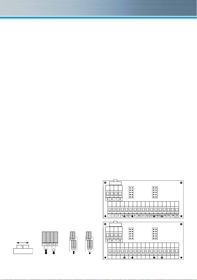
Connector pin assignment
or electric devices such as motors or pumps in
the immediate vicinity of the meter (minimum
distance 1 m). Cables leaving the meter should
not be laid parallel to live cables (230V, minimum
distance 0.2 m).
Declaration of Conformity
ZENNER International GmbH & Co. KG declares
that this product with the number of the EC type-
examination certicate DE-08-MI004-PTB012
complies with the requirements of the EC direc-
tives 2004/22/EC (Measuring instruments direc-
tive) and 89/336/ EEC (electro-magnetic compa-
tibility).
The most up-to-date information about this pro-
duct and of our installation notice can be found at
www.zenner.com
Temperature sensors
2-wire measurement
Supply 1 - 2
Return 3 - 4
4-wire measurement (optionally)
Supply 1 - 2 / 5 - 6
Return 3 - 4 / 7 - 8
Flow sensor
Flow sensor pulse 10
GND 11
Input/Output
I/O 1 pulse 52
GND 53
I/O 2 pulse 54
GND 55
Depending on the meter’s mo-
del the version of the connec-
tion board can differ.
M-Bus
M-Bus L1 24
L2 25
RS-232
DTR 71
GND 72
Tx 73
Rx 74
RS-485
+UB 71
GND 72
A 73
B 74
24
Switch Connection 2-wire Connection 4-wire
4
1 2 3 4 10 11 9 50 51 52 53 54 55 71 72 73 74
Page 5

B
Communication
If water meters with a potential free reed contact
are connected to the inputs the connection can
be made in any direction.
Take care of the polarity when connecting to a
BMS.
The connectors are given twice for the incoming
and outgoing of the M-bus wire.
Height: H = 106 mm
Width: B = 126 mm
Depth: T = 54 mm
H
At calculators with two pulse outputs typically the
rst output (I/O1) gives the energy and the sec-
ond (I/O2) the volume information.
The pulse value is permanently set and corre-
sponds to the last position of the associated dis-
play value.
Example:
Output 1 = energy output
Energy display = XXXXX.XX MWh
Last position = 0.01 MWh = 10 kWh
Output pulse = 10 KWh
The calculator can be ordered with two inputs op-
tionally. The pulse value can be called up in the
display (see the display overview, Level 1).
M-Bus (optional)
The optional M-Bus interface complies with the
norm EN 1434-3 and operates with 2400 baud
xed. It can be set to 300/9600 baud if neces-
sary.
The display resolution shall be selected such that
the display can not run over within a period of
one year.
T
5
Page 6

Installation instructions
Safety instructions
The installation has to be done by qualied per-
sonnel. Read the instructions carefully right up to
the end before starting to mount the device.
The current laws and regulations have to be
observed, especially EN 1434 part 1+6, (in Ger-
many also AGFW directive FW202 and DIN 4713
part 4 and the initial verication directive).
At devices with communication interfaces or
mains supply the general technical rules and the
correspondent regulations have to be followed.
While demounting ow sensors and temperature
sensors make sure no heating water escapes
from the pipe – this can cause burns!
Close valves and release pressure before instal-
lation.
General Information
Take care of:
■ the display must readable at all times,
■ to avoid malfunctions due to other interfe-
rences do not install uorescent lamps, switch
cabinets or electric devices such as motors or
pumps in the immediate vicinity of the meter
(minimum distance 1 m),
■ all welding must be nished,
■ the ambient temperature must not exceed
55°C,
■ the type of temperature sensor must corres-
pond with the calculator,
■ the pulse value of the ow sensor must corres-
pond with the one from the calculator.
The calculator has 7 screwed cable glands for
wires with a diameter between 4,2 and 10 mm.
Keep unused glands closed.
Mind the connection order: temperature sensors
rst, ow sensor afterwards!
multidata is delivered ready for operation.
It does not need any settings or adjustings.
ZENNER International GmbH & Co. KG
Römerstadt 6
D-66121 Saarbrücken
Telephone +49 681 99 676-30
Telefax +49 681 99 676-3100
E-Mail info@zenner.com
Internet www.zenner.com
6
Subject to modications and errors excepted. Any liability for misprints excluded. SAP120966_150622_EN
Page 7

Installation heat calculator
ZENNER recommends to mount the calculator
on the wall. Do not mount the device at the pipe
or attach it directly on the ow sensor.
The mounting adapter at the backside of the cal-
culator can be used for rail mounting or for wall
mounting.
For wall mounting detach the adapter and turn it
180°, attach with at least two screws to the wall
and clip the calculator on it.
For rail mounting lift the adapter a little bit, place
the calculator on the rail and push the adapter
back until it locks.
Connection sensors
The mounting of the temperature sensors should
be done symmetrical with direct immersion.
If immersion sleeves are used they have to be
checked for conformity to MID and have to be
marked accordingly.
The installation of immersion sleeves has to be
done according to DIN EN 1434-2.
■ The sensor cables are marked with colors (red
= supply, blue = return).
■ Do not buckle, extend or shorten the wires!
■ Do only use paired sensors with the same se-
rial number on it.
■ At 2-wire systems the cable length of the tem-
perature sensor for supply and return should
not exceed 2.5 m for PT100, 12.5 m for PT500
and 20.0 m for PT1000.
■ At 4-wire systems the maximum cable length
is 20 m.
■ Consider EN 1434-2 regarding the diameter of
the wires.
■ Supply and return sensors must be inserted
into the immersion sleeves completely.
■ Installation points in the ow sensor can be
used for symmetrical installation of the tem-
perature sensors.
■ Seal temperature sensor after installation to
prevent unauthorized demounting (seals in-
cluded).
■ Do not wrap or install wires along hot pipes.
Switch 2-/4-wire
Calculators equipped with 4-wire measuring sys-
tem can be switched to 2-wire with the switch on
the top left side of the connection board.
Switch to the left for 2-wire, switch position on the
right for 4-wire measurement.
Rail mounting Wall mounting
7
Connection flow sensor
The total length of the wire between ow sensor
and calculator should not exceed 10 m.
With mechanical ow sensors the connection
order is optional. Mind the polarity at electronic
ow sensors.
Page 8

External power supply
A small vertical line appears in the display when
the optional external power supply is on service.
In case of a failure of the external power sup-
ply the devices switches automatically to battery
supply. The battery lifetime can be checked in the
display (level 3). After having reached the date
the battery has to be replaced if needed.
Operation test
Check the calculator for any error codes in the
display after installation (see table for error
codes). Most of the errors can be deleted by
pressing the button. If the error appears perma-
nently, it will be detected at the next measuring
cycle and displayed again. Check weather the
volume information is updated and the displayed
temperatures correspond to the present ones
while the system is running (measuring cycle 2
minutes max.).
When attaching the top cover on the housing
pulses on the inputs can possibly be generated.
Check readings of the inputs and correct if ne-
ces sary.
Care instructions
Clean plastic surfaces with a damp cloth only.
Do not use any scouring or aggressive cleaning
agents! The device is maintenance-free during
the service life.
Sealing
Seal the device with the included seals to pre-
vent unauthorized opening.
Maintenance
Repairs or overhaul are only allowed by the
manufacturer or companies authorized by the
manufacturer.
8
Page 9

Status display / Error codes
The symbols in the table below show the meter’s operational status. The status messages only appear
in the main display (energy)! The temporary display of the warning triangle can be caused by special
operating states and does not always mean that the device is malfunctioning. However, should the symbol
be displayed over a longer period of time you should contact the service company.
Symbol Status Maßnahme
Flow existent
Attention! Check system / device for errors
-
Data transmission
Emergency operation Exchange device
External power supply
Error codes show faults detected by multidata. If more than one error appears, the sum of the error
codes is displayed: Error 1005 = error 1000 and error 5.
.
-
-
Code Error Event
1 Short-circuit return sensor
2 Interruption return sensor
3 Short-circuit supply sensor
4 Interruption supply sensor
5 Hardware error Exchange device
6 Battery empty or wrong temp. sensor Check device / sensor
7
100 Emergency operation Exchange device
1000 Battery life time exceeded Exchange device
2000 Initial verication expired Exchange device
> 8000 Internal hardware error Exchange device
Temperatures out of measuring range
Check sensors, replace if needed
Check sensors, replace if needed
Check sensors, replace if needed
Check sensors, replace if needed
Correction heating system
9
Page 10

Level 1 Level 2
Date month heating energy
Date month input 1
H
H
Date month input 2
H
Monthly logger meter reading
Maximum 24 previous month values
L
L
L
Energy (main display)
Volume
Volume counter 1
Volume counter 2
Segment test
Supply temperature
Return temperature
Temperature difference
Flow
Maximum flow, Average value per
hour since commissioning
Instantaneous power
Maximum power, Average value
since commissioning
S
H H
You can switch levels at
any point in the menu.
Energy at SRD
SRD
L
H
Pulse value counter 1
L
H
Pulse value counter 2
SRD value counter 1
SRD value counter 2
Energy consumption current month
Input 1 current monthly consumption
Input 2 current monthly consumption
Serial number
Monthly logger
Maximum flow and power
Maximum 10 previous month values
L
H
Date month maximum flow
L
H
Date month maximum power
S
S
S
Average value per hour
maximum flow
S
Average value per hour
maximum power
Customer number
Serial number input 1
Serial number input 2
S
L
L
L
10
Page 11

Level 3
Sensor type and installation point
Pulse value
Basic configuration
Model number
End of Battery lifetime
Time
Date
M-bus address
Baud rate
Input display
Error status
Software version
Reading residual energy
Sensor type and installation point
Pulse value
Back to
H
Level 1
Monthly logger meter reading
Maximum 24 previous month values
H
Date month heating energy
H
Date month input 1
H
Date month input 2
L
L
L
S
Monthly value heating energy
S
1. Monthly value input 1
S
2. Monthly value input 2
Note
Depending on your multidata
model its displays can differ in
number and order from those
shown here.
Basic configuration
Model number
End of Battery lifetime
Time
Date
M-bus address
Baud rate
Reading residual energy
Input display
Error status
Software version
Legend
S
Press the button briey (S),
to switch through the display
from top to bottom.
When having reached the
last menu item the device
automatically jumps back
to the menu item at the top
(loop).
L
Press the button for about 2
seconds (L), wait for the door
symbol to appear (upper
right corner of the display)
and then release the button.
The menu is then updated
resp. switches to the sub-
menu.
H
Hold down the button (H)
until the device switches to
another level or switches
back from the sub-menu.
11
Page 12

Disposal
Attention: This device contains a non-remova-
ble and non-rechargeable lithium battery.
Batteries contain substances, which could harm
the environment and might endanger human
health if not disposed of properly.
To reduce the disposal quantity so as unavoid-
able pollutants from electrical and electronic
equipment in waste, old equipment should be
reused prior or materials recycled or reused as
another form.
This is only possible if old equipment, which con-
tains batteries or other accessories are disposed.
Therefore please contact the department of your
local authority which is responsible for waste
disposal. Alternatively a waste disposal via
ZENNER is possible.
Your local or municipal authority or the local
waste disposal company can give you informa-
tion relating the collection points for your used
equipments.
Attention:
Do not dispose of the devices with domestic
waste.
In this way, you will help to protect natural re-
sources and to promote the sustainable reuse
of material resources.
For any question, please contact
info@zenner.com
The most up-to-date information about this prod-
uct and of our installation notice can be found at
www.zenner.com
dtpwork design
Grafik, Design, Webdesign, Layout,
DTP, Reinzeichnung und Produktion
An der Sonnhalde 18
79336 Herbolzheim
http://www.dtpwork.de
12
 Loading...