

Page 1

Alles, was zählt.
Energ ieTech nik
Durchflusssensor IMF
Installation and operating instructions ...7
Flow sensor as mechanical multi jet version
for splitt heat or cooling meters
q
p
3,5 / 6 / 10 m3/h
Notice d’installation et d’utilisation ....... 12
Elément de mesure de volume en version mécanique à jets multiples
En version compteur à éléments séparés d’énergie thermique ou
de frigorie
q
p
3,5 / 6 / 10 m3/h
Istruzioni per il montaggio e l‘utilizzo .... 18
Volumetrica a getto multiplo
Per contatori di calore o di raffrescamento split
q
p
3,5 / 6 / 10 m3/h
Instrucciones de montaje y operación ...22
Sensor de flujo en diseño de medidor de turbina con chorro
múltiple como medidor de refrigeración o medidor de calefacción modular
q
p
3,5 / 6 / 10 m3/h
Montage- und Bedienungsanleitung .......2
Durchflusssensor in Mehrstrahl-Flügelradzählerausführung für
Split-Wärmezähler oder -Kältezähler
q
p
3,5 / 6 / 10 m3/h
Page 2

2
Español
Italiano
Français
English
Deutsch
Allgemeine Hinweise
Diese Anleitung vor Installationsbeginn sorgfältig bis zum Schluss durchlesen!
Die Montage darf nur von dafür qualizierten
Fachhandwerkern durchgeführt werden.
Aktuell gültige Geset ze und Vorschriften sowie
die allgemein anerkannten Regeln der Technik
sind bei d er Mon tage un d Inst allati on zu be ach ten, insbesondere die t echnischen Richtlinien TR
K 8 und K 9 der PTB, die EN 143 4 Teil 1 + 6 und
in Deutschland die AGFW Richtlinien FW202,
FW208 und FW51 0. Die Sicherungsstempel dürfen nicht zerstört werden, da ansonsten die Eichfrist und die Gewährleistung erlischt.
Der Durchusssensor ist bevorzugt in den Rücklauf (bei Wärmezählern kälterer Strang, bei Kältezählern wärmerer Strang) der Anlage einzubauen. Di e Montage - und Bedienung sanleitung
des Rechenwerks und der Temperaturfühler sind
zu beachten.
Vorsicht bei Austritt von Heizwasser bei der
Montage - Verbrühungsgefahr!
Eine ungestörte gerade Zulaufstrecke vor dem
Durchusssensor sowie eine ungestörte gerade
Ablaufstrecke nach dem Durchusssensor ist
nicht erforderlich. Allerdings ist bei Heizungsanlagen mit fehlender Temperaturdurchmischung
bzw. Temperaturschichtung eine Zulaufstrecke
von min. 10 x DN am Einbauort vorzusehen.
Es ist auf ausreichenden Anlagendruck zur Vermeidung von Kavitation zu achten.
■
Vor Erstmontage Anlage gründlich spülen.
■
Frei von Spannungs- / Zugkräften und Vibrationen einbauen.
■
Signalleitungen nicht entlang stromführender
Kabel verlegen.
Der Durchusssensor IMF ist ein Mehrstrahlügelradzähler. Der IMF ist in den Nenngrößen
3,5 m³/ h, 6 m³/h oder 10 m³/h e rhältlic h und ist
so für die verschiedensten Messaufgaben einsetzbar.
Der IMF ist über die Einsatzdauer wartungsfrei.
Der Durchusssensor ist zum Anschluss an
ein separates Rechenwerk für Wärme- oder
Kältezählung und den wahlweisen Einbau im
Vor- oder Rücklauf eines WärmetauscherKreislaufsystems vorgesehen. Zum elektrischen
Ansc h l u s s d i ent ein Kabel, welche s a m Rechen werk einfach angeschlossen werden kann. Reparatur en kö nn en n ur vo m H e r ste l le r vo rg e no mmen werden.
Vor der Montage beachten
■
Der Volumenimpulseingang des Rechenwerks muss kompatibel zu dem Impulsausgang des IMF sein (siehe technische Daten
Impulsausgangsvorrichtung).
■
Impulswertigkeit von Rechenwerk (RW) und
IMF müssen übereinstimmen (Typenschilder
vergleichen!).
■
Der Einbauort (Vor- bzw. Rücklauf) des IMF
muss mit der entsprechenden Angabe auf
dem Rechenwerk übereinstimmen.
■
Der Durchusssensor IMF darf nur mit einem
zu den Anschlussdaten (siehe Daten Durch-
usssensor / Impulsausgangsvorrichtung)
kompatiblen Rechenwerk betrieben werden.
Montage Durchflusssensor
■
Absperrorgane vor und hinter der Einbaustel-
le schließen, Einbaustelle druckentlasten.
■
In der Regel ist dies der Rücklauf (kälterer
Strang bei Heizanlagen , wärmerer Strang bei
Kühlanlagen).
■
Einbauort beachten.
■
Bitte Angabe auf dem Typenschild beachten.
■
Flussrichtung beachten.
■
Diese ist durch einen Pfeil an der Seite des
DFS angegeben.
■
Vorhandenen Durchusssensor / Passstück
ausbauen.
■
Nur neues Dichtmaterial verwenden, Dicht-
ächen säubern und auf Beschädigung
kontrollieren.
■
Neuen Durchusssensor ießrichtungs- und
lagerichtig einbauen.
Page 3

3
■
Das Zählwerk muss immer nach oben zeigen.
■
Absperrorgane langsam öffnen – Anlage
entlüften und in Betrieb nehmen, Druckschläge vermeiden.
■
Einbaustelle auf Dichtigkeit prüfen.
■
Elektrischen Anschluss zum Rechenwerk
herstellen.
■
Inbetriebnahmeprotokoll gemäß PTB-Richtlinie TR K 9 ausfüllen.
Anschluss des Durchflusssensors an ein
Rechenwerk
Zählausgang des IMF mit Volumenimpulseingang
des RW verbinden (üblicher weise Klemme 10 und
11).
Inbetriebnahme
■
Anlage auf Dichtheit prüfen.
■
Bei laufender Anlage Volumen, Energiefortschritt
und Temperaturanzeigen am RW kontrollieren.
■
Nach abgeschlossener Inbetriebnahme Benutzersicherungen anbringen (im Lieferumfang
enthalten).
Wichtigste Merkmale
■
Einbau wahlweise im Vor- oder Rücklauf möglich
■
Korrekte Einbaulage beachten
■
Temperaturbereich 5 °C – 120 °C
■
Verfügbar in q
p
3,5 / 6 / 10 m³/h
Elektromagentische Störungen
Der Durchusssensor IMF erfüllt die nationalen
und internationalen Anforderungen an die Störsicherheit. Um Fehlfunktionen durch darüber hinaus gehende Störungen zu vermeiden, dürfen
Leuchtstoffröhren, Schaltkästen oder elektrische
Verbraucher wie Motoren und Pumpen nicht in
unmittelbarer Umgebung des Durchusssensors
montiert werden (Mindestabstand 1 m).
Die Anschlussleitung nicht parallel zu spannungsführenden Leitungen (230V/400V) verlegen (mind. Abstand 0,2 m).
Konformität und MID-Richtlinie
Der Durchusssensor IMF kann für den Einsatzbereich Wärme (Baumusterprüfbescheinigungsnummer DE-14-MI004-PTB012) oder Kälte
(Baumusterprüfbescheinigungsnummer DE-16M-PTB-0087) verwendet werden. Für den Einsatz bere ich Wär me ist d er DFS na ch der n euen
europäischen Messgeräterichtlinie 2014/32/EU
(MID) und für den Einsatzbereich Kälte nach dem
neuen Mess- und Eichgesetz (MessEG) sowie
der technischen Richtlinie PTB TR K 7 .2 gefertigt
und gepr üf t. Nac h dies en Ric htlin ien er set zt die
Angabe des Jahres der Konformitätsbewertung
die Eichkennzeichnung (auf der Frontseite des
Geräts erkennbar: z.B. M17 = 2017).
Die MI D regelt die Ver wendung von Me ssgerä ten nur bis zu m in Verkehr brin gen bzw. bis zur
Erstinbetriebnahme.
Danach gelten innerhalb der EU weiterhin die jeweiligen nationalen Regelungen für eichpichtige Mes sg e rä te. D ie E ic h frist betr ä gt i n D eu ts c hland unverändert 5 Jahre für Wärmezähler,
Kältezähler und deren Teilgeräte. Nach Ablauf
dieser Fri st darf das M ess ger ät zur A brec hnun g
im geschäftlichen Verkehr nicht mehr eingesetzt
werden.
Die Rege lungen bzw. die Eichfristen können in
anderen EU Ländern abweichend sein.
Bei Fragen wenden Sie sich bitte an
support@zenner.com
Die Konformitätserklärung ist jedem Messgerät
beigefügt. Neueste Informationen zu diesem
Produk t können unter www.zenner.de abgeru-
fen werden.
Page 4

4
Español
Italiano
Français
English
Deutsch
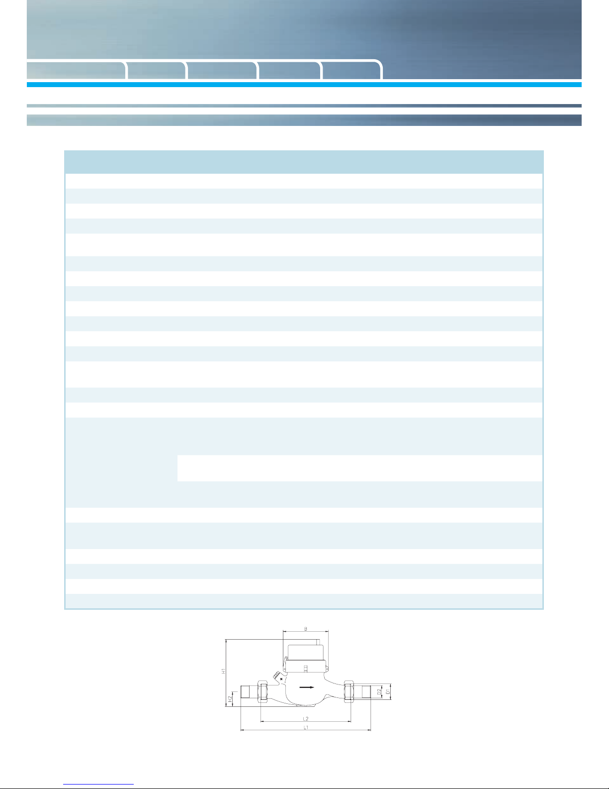
Abmessungen IMF
Technische Daten Durchflusssensor Typ IMF
Nenndurchuss q
p
m³/h 3,5 3,5 6 6 6 6 10 10
Nennweite DN mm 25 25 25 25 32 32 40 40
Zoll 1 -- 1 -- 1 ¼ -- 1 ½ -Baulänge ohne Verschr. L2 mm 260 260 260 260 260 260 300 300
Baulänge mit Verschr. ca. L1 mm 378 -- 378 -- 384 -- 428 -Gewinde Zähler G x B D1 Zoll 1 ¼ Flansch 1 ¼ Flansch 1 ½ Flansch 2 Flansch
Gewinde Verschr. R x D2 Zoll 1 -- 1 -- 1 ¼ -- 1 ½ -Metrologische Klasse Standard: Klasse 2, optional Klasse 3 nach DIN EN 1434
Einbaulage Horizontal (Zählwerk muss nach oben zeigen)
Impulswertigkeit l/Imp 10 10 10 10 10 10 10 10
Impulskabellänge m 1,5 / 3 (verlängerbar um 7)
Maximaler Durchuss q
s
m³/h 7 12 12 12 12 12 20 20
Minimaldurchuss (*) q
i
m³/h 0,14
0,12/
0,24
0,12/
0,24
0,12/
0,24
0,12/
0,24
0,12/
0,24
0,2/
0,4
0,2/
0,4
Medientemperaturbereich °C 5° C ≤ Θq ≤ 120 °C
Druckklasse PN/PS bar 16 (Verschraubung) / 25 (Flansch)
Umgebungsbedingungen /
Einussgrößen
- klimatisch
Höchste Umgebungstemperatur 55 °C
Niedrigste Umgebungstemperatur 5 °C
Schutzklasse IP65
- mechanische
Klasse
M2
- elektromagnetische Klasse
E2
Druckverlust bei q
p
bar ≤ 0,25
Wärmeträger
Wasser
Wasser-Glykol-Gemische (ohne Konformitätsbewertung)
Höhe H1 mm 160 160 160 160 160 160 174 174
H2 mm 40 40 40 40 40 40 50 50
Breite B mm 95 95 95 95 95 95 110 110
Gewicht kg 2,9 4,5 2,9 4,5 2,9 5,8 5,1 9,5
(*) wahlweise
Page 5

5
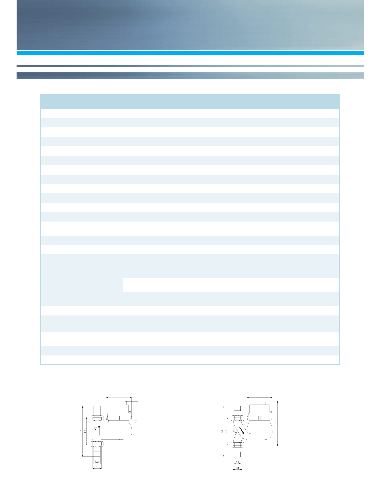
Abmessungen IMF-ST Abmessungen IMF-FA
Technische Daten Durchflusssensor Typ IMF-ST, IMF-FA
Nenndurchuss q
p
m³/h 3,5 3,5 6 6 6 10 10
Nennweite DN mm 25 25 25 25 32 40 40
Zoll 1 1 1 1 1 ¼ 1 ½ 1 ½
Baulänge ohne Verschr. L2 mm 135 150 135 150 150 150 200
Baulänge mit Verschr. ca. L1 mm 253 268 253 268 274 278 328
Gewinde Zähler G x B D1 Zoll 1 ¼ 1 ¼ 1 ¼ 1 ¼ 1 ½ 2 2
Gewinde Verschr. R x D2 Zoll 1 1 1 1 1 ¼ 1 ½ 1 ½
Metrologische Klasse Standard: Klasse 2, optional Klasse 3 nach DIN EN 1434
Einbaulage Horizontal (Zählwerk muss nach oben zeigen)
Impulswertigkeit l/Imp 10 10 10 10 10 10 10
Impulskabellänge m 1,5 / 3 (verlängerbar um 7)
Maximaler Durchuss q
s
m³/h 7 7 12 12 12 20 20
Minimaldurchuss (*) q
i
m³/h 0,14 0,14
0,12/
0,24
0,12/
0,24
0,12/
0,24
0,2/
0,4
0,2/
0,4
Medientemperaturbereich °C 5 °C ≤ Θq ≤ 120 °C
Druckklasse PN/PS bar 16
Umgebungsbedingungen /
Einussgrößen
- klimatisch
Höchste Umgebungstemperatur 55 °C
Niedrigste Umgebungstemperatur 5 °C
Schutzklasse IP65
- mechanische
Klasse
M2
- elektromagnetische Klasse
E2
Druckverlust bei q
p
bar ≤ 0,25
Wärmeträger
Wasser
Wasser-Glykol-Gemische (ohne Konformitätsbewertung)
Höhe H1 mm 195 195 195 195 195
206 (ST)
197 (FA)
231 (ST)
212 (FA)
Breite B mm 95 95 95 95 95 110 110
Gewicht kg 3,1 3,1 3,1 3,1 3,1 5,5 5,5
(*) wahlweise
Page 6

6
ZENNER International GmbH & Co. KG
Römerstadt 6
D-66121 Saarbrücken
Telefon +49 681 99 676-30
Telefax +49 681 99 676-3100
E-Mail info@zenner.com
Internet www.zenner.com
Technische Daten Impulsausgangsvorrichtung
Zählausgang
Klassen nach EN1434-2 OA
Schalterart Reedkontakt
Polaritätsumkehr möglich
Impulsdauer ≥ 100 ms
Impulspause ≥ 100 ms
Prellzeit ≤ 1ms
Größte Eingangsspannung 30 V
Größter Eingangsstrom 27 mA
Schutzwiderstand 68 Ohm
Impulswertigkeit Entsprechend Typenschildangabe
Maximale Anschlussleitungslänge 25 m
Español
Italiano
Français
English
Deutsch
Technische Änderungen vorbehalten. Für etwaige Irrtümer und Druckfehler übernehmen wir keine Haftung.
Page 7

7
General information
Read thes e instr uction s caref ully rig ht up to the
end before starting to mount the device!
The installation has to be done by qualied professional personnel.
The cur rent laws an d regulat ions as wel l as the
genera lly recognis ed codes of pra ctice have to
be observed for installation and mounting, especia lly the P TB tec hnic al guid eline s R K 8 and
K 9 EN1434 par t 1+6 ( in Germany also AGFW
directives FW202, FW208 und FW510). The seal
must not be d estroyed other wise the vali dity of
calibration and warranty is void.
The ow sensor is preferably to be installed in
the colder pipe (for heat meters in colder line and
for for heat meters in w armer li ne) of the system.
The inst a ll at i on a n d op e r at in g in st ructi on s of t h e
calc ulato r and t he tem per atur e sens or s must b e
observed.
Caution with dircharge of hot water during the installation – scalding danger!
No unhin der ed st rai ght i nlet i n fro nt of t he mete r
or outle t behi nd the m eter ne ede d. However, for
heating systems with missing temperature mix-
ing and temperature stratication a straight pipe
length o f min. 10 x D is n ec e ss ary befo re t he installation point.
It is impo rta nt to ensure ad equate system p ressure to avoid cavitation.
■
Flush the system before installation.
■
Mount free of clamping, torsion and vibrations.
■
Do not lay signal cables parallel to live cables.
The ow sensor IMF is a multi jet impeller meter.
The ow sensor IMF is a multi jet impeller meter.
The IM F is available in nom inal sizes 3.5 m ³/h,
6 m³/h or 10 m³/h and is used for a variety of
measurement tasks.
The IM F is maintenance f ree during it s servic e
lifetime. The ow sensor is intended for connection to a se parate ca lculator fo r heat meter s for
the optional installation in the supply or return
pipe of a heat exchanger circuit system. For
electrical connection a cable exists which can be
easily c onnect ed to the cal culator. Repairs m ay
only be carried out by the manufacturer or authorized service partners.
Note before installation
■
The volume pulse input of the calculator must
be compatible to the pulse output of the IMF
(see technical data device of pulse output).
■
Pulse value of calculator unit (RW) and IMF
must match (compare nameplates!).
■
The installation (supply or return) of the IMF is
to be done according to the instruction on the
calculator.
■
The ow sensor IMF may only be operated
with one to the connection data (see data ow
sensor / device of pulse output) compatible
calculator.
Installation flow sensor
■
Close valves upstream and downstream of
the point of installation, release pressure.
■
Normally this is the return (the colder pipe in
heating systems).
■
Respect the installation place.
■
Please observe the indication on the type
plate.
■
Respect the direction of ow.
■
This is indicated by an arrow on the side of
the ow sensor.
■
Dismount the existing ow sensor / tting.
■
Use only new sealing material, clean sealing
surfaces and check for damage.
■
Install the new ow sensor in the correct
ow direction and in the correct installation
position.
■
The register always has to face upwards.
■
Open the valves slowly – purge and start
operation, avoid water hammers make sure
there is no leakage.
■
Check the installation place for leaks.
■
Make electrical connections to the calculator.
Page 8

8
Español
Italiano
Français
English
Deutsch
■
Fill out the commissioning protocol according
to local or legal requirements.
Connection of the flow sensor to the calculator
Connect pulse output of the IMF with volume
pulse input of the calculator (usually terminal 10
and 11).
Commissioning
■
Check system for leaks.
■
Check while the system is running if progress
of volume, power and temperature is shown
on the calculator display.
■
Install user seals (included) after commissioning.
Key Features
■
Can be installed in the supply or return pipe
■
Observe correct installation position
■
Temperature range 5 °C - 120 °C
■
Available in q
p
3,5 / 6 / 10 m³/h
Electro-magnetic interference
The ow sensor IMF fulls the national and international requirements for interference resistanc e. To avoid m alfunct ions due to oth er inter-
ferences, do not install uorescent lamps, switch
cabinets or electric devices such as motors or
pumps in the immediate vicinity of the meter
(minimum distance 1 m).
Cables l eavi ng th e mete r sho uld n ot be l aid p arallel to live cables (230V/400V) (minimum distance 0.2 m).
MID - Initial verification
The ow sensor IMF can be used for the range
of application heat (the examination certicate
number D E-14 - MI0 04- PTB 012) or for the r ange
of application cooling (the examination cer-
ticate number DE-16-M-PTB-0087). The ow
sensor I MF for the range of applic ation heat is
produc ed an d teste d in co mpli anc e with t he European Measuring Instruments Directive (MID).
The ow sensor IMF for the range of application
cooling is produced and tested in compliance
with th e measurement a nd calibrat ion (Weight s
and Mea sur e s Ac t). Th e pa rt for th e c o o l in g application is produced and tested in compliance
with the German PTB regulation K7 .2. According
to this dir ective, devic es are no long er carr ying
an initial verication stamp, but rather the year of
the devic e’s decla rati on of c onfo rmi ty (rec ogn izable on t he front of th e dev i c e, f o r exa mp l e: M17
= 2017).
The MID c ontrols the use of measuring device
up to the mo me nt th ey are p la c ed o n t he m ar ket
resp. their rst putting into use.
After this, the national regulations for devices
subject to compulsory verication apply within
the EU. The duration of initial verication validity
in Ger m a ny r e m a i n s 5 ye ars for he at meters. Af ter this period has expired, the measuring device
may no long er be used f or billi ng in com merci al
use.
The reg ulat io ns re sp. val idi t y per i od m ay var y in
other countries of the EU.
If you have questions, please direct them to
support@zenner.com
The declaration of conformity is attached to each
measuring instrument. The latest information
about this product can be accessed or downloaded from www.zenner.com
Page 9

9
Dimensions IMF
Technical data flow sensor model IMF
Nominal ow q
p
m³/h 3.5 3.5 6 6 6 6 10 10
Nominal diameter DN mm 25 25 25 25 32 32 40 40
inch 1 -- 1 -- 1 ¼ -- 1 ½ -Overall length without
connectors
L2 mm 260 260 260 260 260 260 300 300
Length with connectors
approx.
L1 mm 378 -- 378 -- 384 -- 428 --
Thread meter G x B D1 inch 1 ¼ Flange 1 ¼ Flange 1 ½ Flange 2 Flange
Thread connector R x D2 inch 1 -- 1 -- 1 ¼ -- 1 ½ -Metrological class Standard class 2, optionally 3 according to EN 1434
Installation position horizontal (the register always has to face upwards)
Pulse value l/pulse 10 10 10 10 10 10 10 10
Cable length m 1,5 / 3 (it will be extendable by 7 m)
Maximum ow q
s
m³/h 7 12 12 12 12 12 20 20
Minimum ow * q
i
m³/h 0.14
0.12
0.24
0.12
0.24
0.12
0.24
0.12
0.24
0.12
0.24
0.2
0.4
0.2
0.4
Temperature range °C 5° C ≤ Θq ≤ 120 °C
Nominal pressure PN/PS bar 16 (Threaded connection) / 25 (Flange)
Ambient conditions /
climatic inuencing
- climatic
Highest permissible ambient temperature 55 °C
Lowest permissible ambient temperature 5 °C
Protection class IP65
- metrological
class
M2
- elektromagnetic
class
E2
Pressure loss at q
p
bar ≤ 0,25
Heat carrier
Water
glycol (without Declaration of conformity)
Height H1 mm 160 160 160 160 160 160 174 174
H2 mm 40 40 40 40 40 40 50 50
Width B mm 95 95 95 95 95 95 110 110
Weight kg 2.9 4.5 2.9 4.5 2.9 5.8 5.1 9.5
* optionally
Page 10

10
Dimensions
IMF-ST
Dimensions
IMF-FA
Español
Italiano
Français
English
Deutsch
Technical data flow sensor model IMF-ST, IMF-FA
Nominal ow q
p
m³/h 3.5 3.5 6 6 6 10 10
Nominal diameter DN mm 25 25 25 25 32 40 40
inch 1 1 1 1 1 ¼ 1 ½ 1 ½
Overall length without
connectors
L2 mm 135 150 135 150 150 150 200
Length with connectors
approx.
L1 mm 253 268 253 268 274 278 328
Thread meter G x B D1 inch 1 ¼ 1 ¼ 1 ¼ 1 ¼ 1 ½ 2 2
Thread connector R x D2 inch 1 1 1 1 1 ¼ 1 ½ 1 ½
Metrological class Standard class 2, optionally 3 according to EN 1434
Installation position horizontal (the register always has to face upwards)
Pulse value l/pulse 10 10 10 10 10 10 10
Cable length m 1,5 / 3 (it will be extendable by 7 m)
Maximum ow q
s
m³/h 7 7 12 12 12 20 20
Minimum ow * q
i
m³/h 0.14 0.14
0.12/
0.24
0.12/
0.24
0.12/
0.24
0.2/
0.4
0.2/
0.4
Temperature range °C 5 °C ≤ Θq ≤ 120 °C
Nominal pressure PN/PS bar 16
Ambient conditions /
climatic inuencing
- climatic
Highest permissible ambient temperature 55 °C
Lowest permissible ambient temperature 5 °C
Protection class IP65
- metrological
class
M2
- elektromagnetic
class
E2
Pressure loss at q
p
bar ≤ 0,25
Heat carrier
Water
glycol (without Declaration of conformity)
Height H1 mm 195 195 195 195 195
206 (ST)
197 (FA)
231 (ST)
212 (FA)
Width B mm 95 95 95 95 95 110 110
Weight kg 3.1 3.1 3.1 3.1 3.1 5.5 5.5
* optionally
Page 11

11
Subject to modications and errors excepted. Any liability for misprints excluded.
Technical data device of pulse output
counter output
Classes in accordance withEN1434-2 OA
Switch variants reed contact
Polarity reversal possible
Duration of the pulse ≥ 100 ms
Pulse break ≥ 100 ms
Bounce time ≤ 1ms
Input magnitude, max. 30 V
Input current, max. 27 mA
Protection resistor 68 Ohm
Pulse value in accordance with the details on the label
Connection line length, max. 25 m
ZENNER International GmbH & Co. KG
Römerstadt 6
D-66121 Saarbrücken
Telefon +49 681 99 676-30
Telefax +49 681 99 676-3100
E-Mail info@zenner.com
Internet www.zenner.com
Page 12

12
Español
Italiano
Français
English
Deutsch
Informations générales
Ces instructions de montage doivent être lues
soigneusement dans leur intégralité avant le
début de l’installation!
Le montage ne peut être effectué que par du per-
sonnel spécialisé et qualié.
Les lois et réglementations en vigueur actuellement ains i que les règl es général es techniqu es
sont à pre ndre en comp te lors de l’assem blage
et de l’installation, en particulier celles de type
EN1434, par tie 1 + 6 (en Allema gne égalem ent
les directives AGF W FW02,FW208 et FW510).
Les scellements ne doivent pas être endommagés, le cas échéant la validité du certicat d’étalonnage et la garantie est alors nulle.
Le capteur de débit doit de préférence être
instal lé dans le segment f roid (dans le cas de s
compteurs d’énergie thermique sur le circuit retour, dans le cas des compteurs de frigorie sur le
circu it aller) du sys tème. L’inst allat ion et les i nstructions de service du calculateur et des sondes
de températures sont à respecter.
Attent i o n e n cas d’écoule m e nt d ’eau ch au d e d urant le montage / Risque de graves brûlures!
Pas de longueurs droites nécessaires en amont
et en aval du cap teu r de d é bi t. N é a nm oi ns , p ou r
toutes les installations de chauffage sans mélan-
geur de température et sans stratication de
tempér atur e, il fa ut pr évoir 10 x DN au m ini mum
de longueurs droites en amont du compteur.
Pour éviter le phénomène de cavitation, une
pression sufsante doit être assurée sur l’installation.
■
Rincer soigneusement l’installation avant le
montage initial.
■
Installer loin de toute tensions / force de traction et vibrations.
■
Ne pas poser les conducteurs de signaux le
long de câbles électriques sous tension.
L’élément de mesure de volume IMF est un
compteur à jets multiples à turbine. L’élément
de mesure de volume IMF est disponible dans
les dimensions nominales 3,5 m³/h, 6 m³/h ou
10 m³/h et est utilisé pour des opérations de mesure très variées.
Il ne néc essite auc une maintena nce penda nt la
durée de son utilisation.
L’élément de me sure de volume est destiné au
branchement à un calculateur séparé pour énergie thermique et au montage au choix sur le système aller ou retour d’un échangeur de chaleur à
circu it fe rm é. Un c âbl e qui p eut êt re si mpl eme nt
conne cté au c alc ulateu r perm et le bra nche ment
électrique. La maintenance du produit ne peut
être effectuée que par le fabricant.
A respecter avant le montage
■
L’entrée d’impulsion de débit du calculateur
doit être compatible à la sortie d’impulsion de
l’IMF (voir données techniques dispositif de
sortie d’impulsion).
■
Valeur d’impulsion du calculateur (RW) et
IMF doivent correspondre (comparer plaque
signalétiques!).
■
Le point d’installation (aller ou retour) de l’IMF
doit correspondre avec la mention équivalente sur le calculateur.
■
Il faut faire fonctionner l‘élément de mesure
de volume IMF qu‘avec le calculateur
compatible du point de vue des données de
connexion (voir données élément de mesure
de volume/ dispositif de sortie d‘impulsions).
Installation du mesureur de volume
■
Couper les organes de fermeture devant et
derrière l’emplacement de montage, évacuer
la pression.
■
En général il s‘agit du circuit retour (segment
le plus froid dans le cas d‘installations de
chauffage).
■
Respecter le point d‘installation
■
Respecter l‘indication sur la plaque signalétique
■
Respecter la direction du ux
■
Celle-ci est indiquée par une èche sur le
côté du mesureur de volume.
■
Démonter l’ancien mesureur de volume /
adaptateur
■
Utiliser uniquement du matériel d’étanchéité
neuf, nettoyer les surfaces d’étanchéité et
contrôler l’absence d’endommagements.
Page 13

13
■
Installer le nouveau mesureur de volume en
respectant la direction de ux et de montage.
■
Le calculateur doit toujours être orienté vers
le haut.
■
Ouvrir lentement les organes de fermeture –
éviter les coups de pression.
■
Contrôler l’emplacement de l’installation pour
vérier l’étanchéité.
■
Effectuer le branchement électrique au
calculateur.
■
Remplir le protocole de mise en service
conformément aux exigences légales et / ou
locales.
Branchement de l’élément de mesure de
volume au calculateur
Connecter la sortie d’impulsion de l’IMF avec
l’entrée d’ impulsion de débit du calculateur (habituellement borne 10 et 11).
Mise en route
■
Vérier si l’installation est étanche.
■
Contrôler le débit, la consommation d’énergie
et l’afchage des températures au calculateur
durant le fonctionnement de l’installation.
■
Une fois la mise en route effectuée, installer
les sécurités utilisateur (comprises dans la
livraison).
Caractéristiques principales
■
Peut être installé dans le circuit aller ou retour
■
Observer la position d’installation correcte
■
Gamme de température 5 °C – 120 °C
■
Disponible en q
p
3,5 / 6 / 10 m³/h
Perturbations électromagnétiques
L’élément de mesure de volume IMF remplit
les exigences nationales et internationales en
matièr e d’imm unité au b rui t. Pou r éviter l es dys fonctionnements causés par des perturbations
électromagnétiques, les tubes luminescents,
les boîtiers électroniques ou les équipements
cons ommant de l ’électri cité c omme les m oteurs
et les pompes ne doivent pas être montés à
proximité du compteur (distance minimale d’un
mètre).
Les ls sortant du compteur ne doivent pas être
installés parallèlement aux ls conduisant le
coura nt du résea u élect rique (23 0V / 400V, distanceminimale 0,2 m).
KEtalonnage et Directive MID
L’élément de mesure de volume IMF peut être
utilisé dans le domaine de l’énergie thermique
(attestation d’examen de type (DE-14-MI004PTB012) ou de frigorie (attestation d’examen
de typ e D E-16-M-PTB- 0087). D ans l e c a dr e du
champ d’application de l’énergie thermique le
capteur de débit est fabriqué, contrôlé et marqué
selon la n ouvelle Dire ctive des Ins truments d e
Mesure (MID) et dans le cadre du champ d’appli-
cation de l’énergie frigorique selon la nouvelle
législation de mesure et de métrologie (MessEG). La partie mesurant la frigorie est fabriquée
et étalonnée conformément aux dispositions
K7.2 du service physico-technique allemand
(PTB). Selon cette directive, aucune date de
renouvellement n ’est stipulée sur l’appareil, mais
seule l’année de déclaration de conformité gure
sur la façade de l’appareil (exemple M1 7 = 201 7).
La directive MID régit uniquement l’utilisation
d’instr um e nt s de m es ur e ju sq u’à leur ar r i vée s ur
le marché et leur première mise en service.
Ce sont ensuite les ré glementatio ns nationales
qui s’appliquent à l’intérieur de l’Union européenne pour des appareils soumis à l’obligation
d’étalonnage. La validité d’étalonnage s’élève
à cinq ans en Allemagne pour les compteurs
d’énergie thermique et les pièces. A l’expiration
de cette période, l’appareil de mesure ne peut
plus être u ti lis é c om me o ut il d e fac tu ra ti on c o m merciale.
Les réglementations ou les durées de validité
des compteurs peuvent varier d’un pays européen à l’autre.
Pour toutes les questions, veuillez vous adresser à notre support technique
zenner.france@zenner.com
La déc la r a t i o n de conformité est j oi nt e à c h a qu e
compteur. V ous trouverez les informations mises
à jour sur c e prod uit ainsi q ue notr e manuel d e
montage et d’installation dernière édition sur
notre site www.compteurs-zenner.fr
Page 14
14
Dimensions IMF
Español
Italiano
Français
English
Deutsch
Caracteristiques techniques mesureur de volume type IMF
Débit permanent q
p
m³/h 3,5 3,5 6 6 6 6 10 10
Diamètre nominal DN mm 25 25 25 25 32 32 40 40
pouce 1 -- 1 -- 1 ¼ -- 1 ½ --
Longueur sans raccords L2 mm 260 260 260 260 260 260 300 300
Longueur avec raccords
env.
L1 mm 378 -- 378 -- 384 -- 428 --
Filetage compteur G x B D1 pouce 1 ¼ Bride 1 ¼ Bride 1 ½ Bride 2 Bride
Filetage raccord R x D2 pouce 1 -- 1 -- 1 ¼ -- 1 ½ -Classe métrologique Standard cl. 2, en option cl. 3 conformément EN 1434
Position d'installation horizontal (Le calculateur doit toujours être orienté vers le haut)
Valeur d'impulsion l/Imp. 10 10 10 10 10 10 10 10
Longueur des câbles m 1,5 / 3 (extensible à 7)
Débit maximal q
s
m³/h 7 12 12 12 12 12 20 20
Débit minimal* q
i
m³/h 0,14
0,12/
0,24
0,12/
0,24
0,12/
0,24
0,12/
0,24
0,12/
0,24
0,2/
0,4
0,2/
0,4
Plage de température °C 5° C ≤ Θq ≤ 120 °C
Classe de pression PN/PS bar 16 (raccord leté) / 25 (xation par bride)
Conditions ambiantes/
inuences climatiques
- climatique
Température ambiante max autorisée 55 °C
Température ambiante mini autorisée 5 °C
Classe de protection IP65
- Classe métrologique
M2
- Classe électromagnétique
E2
Perte de charge à q
p
bar ≤ 0,25
Agent caloporteur
Eau
glycol (sans déclaration de conformité)
Hauteur H1 mm 160 160 160 160 160 160 174 174
H2 mm 40 40 40 40 40 40 50 50
Largeur B mm 95 95 95 95 95 95 110 110
Poids kg 2,9 4,5 2,9 4,5 2,9 5,8 5,1 9,5
(*) au choix
Page 15

15
Dimensions
IMF-ST
Dimensions
IMF-FA
Caractéristiques techniques des modèles IMF-ST, IMF-FA
Débit permanent q
p
m³/h 3,5 3,5 6 6 6 10 10
Diamètre nominal DN mm 25 25 25 25 32 40 40
pouce 1 1 1 1 1 ¼ 1 ½ 1 ½
Longueur sans raccords L2 mm 135 150 135 150 150 150 200
Longueur avec raccords
env.
L1 mm 253 268 253 268 274 278 328
Filetage compteur G x B D1 pouce 1 ¼ 1 ¼ 1 ¼ 1 ¼ 1 ½ 2 2
Filetage raccord R x D2 pouce 1 1 1 1 1 ¼ 1 ½ 1 ½
Classe métrologique Standard cl. 2, en option cl. 3 conformément EN 1434
Position d'installation horizontal (Le calculateur doit toujours être orienté vers le haut)
Valeur d'impulsion l/Imp. 10 10 10 10 10 10 10
Longueur des câbles m 1,5 / 3 (extensible par 7)
Débit maximal q
s
m³/h 7 7 12 12 12 20 20
Débit minimal* q
i
m³/h 0,14 0,14
0,12/
0,24
0.12/
0,24
0,12/
0,24
0,2/
0,4
0,2/
0,4
Plage de température °C 5 °C ≤ Θq ≤ 120 °C
Classe de pression PN/PS bar 16
Conditions ambiantes/
inuences climatiques
- climatique
Température ambiante max autorisée 55 °C
Température ambiante mini autorisée 5 °C
Classe de protection IP65
- Classe métrologique
M2
- Classe électromagnétique
E2
Perte de charge à q
p
bar ≤ 0,25
Agent caloporteur
Eau
glycol (sans déclaration de conformité)
Hauteur H1 mm 195 195 195 195 195
206 (ST)
197 (FA)
231 (ST)
212 (FA)
Largeur B mm 95 95 95 95 95 110 110
Poids kg 3,1 3,1 3,1 3,1 3,1 5,5 5,5
(*) au choix
Page 16
16
Sous réserve de modications techniques. Nous déclinons toute responsabilité concernant d’éventuelles erreurs et errata.
Compteurs ZENNER S.A.R.L.
7, rue Gustave Eiffel
F-87410 Le Palais sur Vienne
Téléphone 05 55 38 37 09
Télécopie 05 55 38 37 15
Courriel zenner.france@zenner.com
Internet www.compteurs-zenner.fr
Données techniques dispositif de sortie d’impulsion
Sortie comptage
Classes selon EN1434-2 OA
Type d’interrupteur Contacteur Reed
Inversion de polarité possible
Durée d’impulsion ≥ 100 ms
Pause d’impulsion ≥ 100 ms
Temps de rebondissement ≤ 1ms
Tension d’entrée max 30 V
Courant d’entrée max 27 mA
Résistance de protection 68 Ohm
Valeur d’impulsion Conformément plaque signalétique
Longueur max câble de raccordement 25 m
Español
Italiano
Français
English
Deutsch
Page 17

17
Indicazioni generali
Prima di iniziare l‘installazione leggere attentamente queste istruzioni per l‘uso dall‘inizio alla
ne!
Il montaggio deve essere eseguito solt anto dal
personale tecnico qualicato.
Durante il montaggio e l‘installazione attenersi
alle norme e alle speciche attualmente vigenti
nonché ai principi tecnici generalmente riconosciut i, in parti colare EN1434 pa rte 1+ 6 e le direttive AGFW FW202, FW208 e FW510. Il sigillo
non deve ess e re r o tto altr im e nt i d e c a d on o s ia l a
garanzia sia la calibrazione.
È preferibile montare il sensore di usso nella
par te d e l l‘impia nt o p i ù f r e d d a (nel caso di c o ntatori di c alore n ella par te del c ircui to più fre dda,
mentre nel caso di contatori di frigorie nella parte
più cal da). Atteners i alle istr uzioni di m ontagg io
ed uso del l ‘un it à d i c a lcolo e del la s o nd a di t emperatura.
Attenzione alla fuoriuscita di acqua di riscaldamento durante il montaggio - pericolo di ustione!
Non è nec essario pr evedere un tratto ret tilineo
privo di turbolenze a monte e a valle della volumetr ic a. Tuttavia per i mpia nti di r isc alda mento
privi di temperatura straticata è necessario un
trat to rettilineo d i almeno 10 volte il diamet ro a
monte del punto di installazione.
Attenzione al livello di pressione dell‘impianto
per evitare fenomeni di cavitazione.
■
Lavare a fondo l‘impianto prima di eseguire il
primo montaggio.
■
Montare senza applicare forze meccaniche,
trazione e vibrazioni.
■
Non montare i cavi di segnalazione lungo il
cavo destinato alla conduzione della corrente
elettrica.
La volumetrica modello IMF è a getto multiplo ed
è dispon ibi le n ell e dim en sio ni n om ina li 3, 5 m³/ h,
6 m³/h o 10 m³/h.
La volumetrica IMF non necessita di par ticolare manutenzione durante tutta la sua durata di
utilizzo.
La volumetrica è prevista per essere collegata
ad una unità di calcolo separata, per il montaggio
a scelta sulla man data o sul ritorno di u n circuit o
di riscaldamento/raffrescamento. Per il collegamento elettrico serve un cavo che può essere
collegato semplicemente all‘unità di calcolo.
Eventuali riparazioni possono essere eseguite
soltanto dal produttore.
Prima del montaggio rispettare i seguenti
punti
■
La ricezione degli impulsi di volume dell‘unità di calcolo deve essere compatibile con
l‘emissione di impulsi della volumetrica IMF
(vedi dati tecnici).
■
Il valore degli impulsi dell‘unità di calcolo
(UC) e quello della volumetrica IMF devono
coincidere (cfr. targhette!).
■
Il punto di installazione (mandata o ritorno)
della volumetrica deve coincidere con il dato
relativo indicato nell‘unità di calcolo.
■
La volumetrica IMF deve essere collegata
soltanto con un‘unità di calcolo compatibile
(vedi dati della volumetrica/ uscite impulsive).
Montaggio della volumetrica
■
Chiudere la rubinetteria posizionata prima
e dopo il punto di installazione, scaricare la
pressione sul punto di montaggio.
■
Solitamente si tratta del ritorno (circuito più
freddo in impianti di riscaldamento).
■
Fare attenzione al punto di installazione.
■
Fare attenzione ai dati della targhetta.
■
Fare attenzione alla direzione del usso.
■
Questa è indicata da una freccia sul lato della
volumetrica.
■
Smontare la volumetrica esistente.
■
Utilizzare soltanto guarnizioni nuove, pulire
le superci delle guarnizioni e controllare la
presenza di eventuali danneggiamenti.
■
Montare la volumetrica nuova in base alla
direzione di usso e alla posizione.
■
L‘orologeria deve essere sempre orientata
verso l‘alto.
Page 18

18
Español
Italiano
Français
English
Deutsch
■
Aprire lentamente la valvola - scaricare l‘aria
dell‘impianto e metterlo in funzione, evitare
colpi d‘ariete.
■
Vericare la tenuta del punto di installazione.
■
Eseguire il collegamento elettrico all‘unità di
calcolo.
■
Compilare il protocollo della messa in funzione in base alla direttiva PTB TR K 9 o altre
normative locali.
Collegamento della volumetrica ad un‘unità
di calcolo
Collegare l’uscita impulsiva della volumetrica
con l’ingresso della parte elettronica (solitamen te morsetti 10 e 11).
Messa in funzione
■
Vericare la tenuta dell‘impianto.
■
Durante il funzionamento dell‘impianto
controllare gli indicatori di volume, consumo
energetico e temperatura dell‘unità di calcolo.
■
Dopo aver concluso la messa in funzione
applicare i sigilli di sicurezza per l‘utente
(contenuti nella dotazione di serie).
Principali caratteristiche
■
Possibile montaggio a scelta sul circuito della
mandata o del ritorno.
■
Rispettare la corretta posizione di montaggio.
■
Range temperatura 5 °C – 120 °C
■
Disponibile in qp 3,5 / 6 / 10 m³/h
Interferenze elettromagnetiche
La volumetrica IMF rispetta i requisiti nazionali
internazionali sulla protezione da eventuali interferenze. Per evitare possibili malfunzionamenti derivanti da interferenze, non montare nelle
immediate vicinanze della volumetrica lampade
uorescenti, scatole di comando o strumenti
elett rici c ome mot ori e pom pe (distanz a minima
1m).
Non po siz io na re i l c avo di c o ll eg am ent o pa ra llelamente ai cavi destinati al passaggio di corrente
elettrica (230V/400V) (distanza minima 0,2 m).
Conformità e direttiva MID
La volumetrica IMF può essere utilizzata per
misurare l’energia termica (certicato nr. DE-
14-MI004-PTB012) o di raffreddamento (certi-
cato nr. DE-16-M-PTB-0087). La volumetrica
è prodotta, testata e marcata per applicazione
con energia termica secondo la nuova normativa europe a de gl i st r ume nt i di mi sur a zi on e (M ID)
e per appl icazi one in imp ianti di raf fre scame nto
seco ndo la nuova legg e di taratura . La parte di
misurazione delle frigorie viene prodotta e tarata
secondo le indicazioni del PTB K7.2. Per questo motivo s ull‘a ppa rec ch io no n vi ene a ppli c ato
nessun marchio di taratura, ma viene indicato l‘anno in c ui è stata dichiarata la conformità
dell‘apparecchio (riconoscibile sul lato frontale
ad esempio M17 = 2017).
La MID regola l‘utilizzo degli apparecchi di mi-
surazione solo nché vengono messi in circolazione ovvero no alla prima messa in funzione.
In base a ta le principi o, all‘in termo dell‘ UE valgono inoltre anche i rispettivi regolamenti nazionali per gli apparecchi soggetti ad obbligo
di tarat ura. La du rata de lla validi tà di ta ratura i n
Germania resta invariata a 5 anni per i contatori
di calo re e per i re lativi a pparec chi c ompon enti.
Alla scadenza di questo termine l‘apparecchio di
misurazione non può essere più impiegato per la
contabilizzazione.
Attenzione: queste n ormative e la loro validità
posso n o e s s e r e di ve r s i a s e conda del l a nazione
europea.
In caso di domande vi potete rivolgere a:
info@zenneritalia.it
La dichiarazione di conformità è allegata ad ogni
strumento. Potete trovare ulteriori informazioni relativamente a questo prodotto sul ns. sito:
www.zenneritalia.it
Page 19

19
Dimensioni IMF
Volumetrica a getto multiplo IMF
Portata nominale q
p
m³/h 3,5 3,5 6 6 6 6 10 10
Diametro nominale DN mm 25 25 25 25 32 32 40 40
Pollici 1 -- 1 -- 1 ¼ -- 1 ½ -Lunghezza senza bocchettoni
L2 mm 260 260 260 260 260 260 300 300
Lunghezza con bocchettoni
(circa)
L1 mm 378 -- 378 -- 384 -- 428 --
Filettatura del contatore
G x B
D1 Pollici 1 ¼ Flangia 1 ¼ Flangia 1 ½ Flangia 2 Flangia
Filetto del bocchettone R x D2 Pollici 1 -- 1 -- 1 ¼ -- 1 ½ -Classe metrologica Standard Classe 2, su richiesta Classe 3 secondo EN 1434
Posizione di installazione orizzontale (L‘orologeria deve essere sempre orientata verso l‘alto)
Valore impulsivo l/Imp. 10 10 10 10 10 10 10 10
Lunghezza del cavo m 1,5 / 3 (allungabile di 7 m)
Portata massima q
p
m³/h 7 12 12 12 12 12 20 20
Portata minima* q
i
m³/h 0,14
0,12/
0,24
0,12/
0,24
0,12/
0,24
0,12/
0,24
0,12/
0,24
0,2/
0,4
0,2/
0,4
Campo temperatura °C 5° C ≤ Θq ≤ 120 °C
Classe di pressione PN/PS bar 16 (attacco lettato) / 25 (angia)
Condizioni ambientali /
inuenze possibili
- Climatico
Max temperatura ambiente 55 °C
Min. temperatura 5 °C
Classe di protezione IP 65
- classe meccanica
M2
- classe elettromagnetica
E2
Perdita di carico a q
p
bar ≤ 0,25
Fluido vettore
Acqua
glicolata (senza dichiarazione di conformità)
Altezza H1 mm 160 160 160 160 160 160 174 174
H2 mm 40 40 40 40 40 40 50 50
Larghezza B mm 95 95 95 95 95 95 110 110
Peso kg 2,9 4,5 2,9 4,5 2,9 5,8 5,1 9,5
(*) a richiesta
Page 20

20
Español
Italiano
Français
English
Deutsch
Dimensioni
IMF-ST (a usso ascendente)
Dimensioni
IMF-FA (a usso discendente)
Dati tecnici volumetrica a getto multiplo modello IMF-ST, IMF-FA
Portata nominale q
p
m³/h 3,5 3,5 6 6 6 10 10
Diametro nominale DN mm 25 25 25 25 32 40 40
Pollici 1 1 1 1 1 ¼ 1 ½ 1 ½
Lunghezza senza bocchettoni
L2 mm 135 150 135 150 150 150 200
Lunghezza con bocchettoni
(circa)
L1 mm 253 268 253 268 274 278 328
Filettatura del contatore
G x B
D1 Pollici 1 ¼ 1 ¼ 1 ¼ 1 ¼ 1 ½ 2 2
Filetto del bocchettone R x D2 Pollici 1 1 1 1 1 ¼ 1 ½ 1 ½
Classe metrologica Standard Classe 2, su richiesta Classe 3 secondo EN 1434
Posizione di installazione orizzontale (L‘orologeria deve essere sempre orientata verso l‘alto)
Valore impulsivo l/Imp. 10 10 10 10 10 10 10
Lunghezza del cavo m 1,5 / 3 (allungabile di 7 m)
Portata massima q
s
m³/h 7 7 12 12 12 20 20
Portata minima* q
i
m³/h 0,14 0,14
0,12/
0,24
0,12/
0,24
0,12/
0,24
0,2/
0,4
0,2/
0,4
Campo temperatura °C 5° C ≤ Θq ≤ 120 °C
Classe di pressione PN/PS bar 16
Condizioni ambientali /
inuenze possibili
- Climatico
Max temperatura ambiente 55 °C
Min. temperatura 5 °C
Classe di protezione IP 65
- classe meccanica
M2
- classe elettromagnetica
E2
Perdita di carico a q
p
bar ≤ 0,25
Fluido vettore
Acqua
glicolata (senza dichiarazione di conformità)
Altezza H1 mm 195 195 195 195 195
206 (ST)
197 (FA)
231 (ST)
212 (FA)
Larghezza B mm 95 95 95 95 95 110 110
Peso kg 3,1 3,1 3,1 3,1 3,1 5,5 5,5
(*) a richiesta
Page 21

21
Dati tecnici uscita impulsiva
Uscita contatore
Classe secondo EN 1434-2 OA
Tipo di contatto contatto reed
Inversione di polarità possibile
Durata impulso ≥ 100 ms
Pausa impulso ≥ 100 ms
Tempo di rimbalzo ≤ 1ms
Tensione di ingresso max. 30 V
Corrente in ingresso max. 27 mA
Resistenza 68 Ohm
Valore impulsivo corrisponde a quanto scritto sulla targhetta
Lunghezza collegamento max. 25 m
Ci si riserva la facoltà di apportare modiche tecniche. Non siamo responsabili di eventuali errori di stampa.
Zenner Srl
Via Marzabotto 85
I - 40050 Funo di Argelato (BO)
Telefono +39 051 198 733 80
Fax +39 051 198 733 99
E-Mail info@zenneritalia.it
Internet www.zenneritalia.it
Page 22

22
Español
Italiano
Français
English
Deutsch
Observaciones generales
Leer detenidamente estas instrucciones hasta el
nal antes de empezar la instalación!
El montaje solo puede ser realizado por especia-
listas cualicados.
Durante el montaje e instalación se deben tener
en cuent a las leyes y reglam entos vigente s así
como las normas técnicas reconocidas, especialm ente la EN1434 p arte 1+6 y las Dire ctivas
nacio nales e n vigo r. Los sellos de s egur idad no
se deben e str op ear, porque s ino l a gar antía y la
vigencia de la calibración expira.
El sensor de ujo (la unidad volumétrica) debe
montar se p refer entem ente en e l ram al fr ío de la
instalación (en el caso de medidores de calefacción, en el retorno). Hay que tener en cuenta las
instr ucc io nes d e mont aje y m anej o de la un idad
digital y de las sondas de temperatura.
Cuidado a nte la posi ble sali da de agua c aliente
durante el montaje: ¡peligro de escaldaduras!
No es nec e sa r io un t r amo r ec to s in al ter ac io ne s
antes del sensor de ujo, ni tampoco lo es un
tramo d e sal id a rec to s in al ter ac io nes t ra s dic h o
sensor. Por lo dem ás, en cas o de insta lacion es
de calefacción sin entremezclado térmico o estraticación térmica, se debe prever un tramo
recto de mín. 10 x DN en el lugar de montaje.
Se debe procurar que la instalación tenga una
presión suciente para evitar la cavitación.
■
Antes del primer montaje, enjuagar a fondo la
instalación.
■
Realizar el montaje sin fuerzas de tensión/
tracción ni vibraciones.
■
No conducir los cables de señal junto a cables conductores de corriente.
El sensor de ujo IMF es un contador de turbina
de chor r o mú lti pl e. El I M F est á d isp o nib le e n t a maños nominales de 3,5 m³/h, 6 m³/h o 10 m³/h y,
por tanto, se puede utilizar para las más diversas
tareas de medición.
El IMF no necesita mantenimiento durante su
período de uso.
El sensor de ujo está previsto para su conexión
a un calc ulador (unidad digit al) de un contado r
de energía té rmic a para el mo ntaje op ciona l en
la ida o en el r etorno de un si stema de circ uito
de intercambiadores de calor. Para la conexión
eléctrica se utiliza un cable que se puede conectar fác ilmente en l a unidad di gital. So lo el fabr icante está autorizado a realizar reparaciones.
Aspectos a tener en cuenta antes del
montaje
■
La entrada de impulsos de volumen del calculador debe ser compatible con la salida de
impulsos del IMF (véanse los datos técnicos).
■
El valor de impulsos del calculador y del IMF
deben coincidir (¡comparar las placas de
identicación!).
■
El lugar de montaje (ida o retorno) del IMF
debe coincidir con el dato correspondiente en
el calculador.
■
El sensor de ujo IMF sólo se debe utilizar
con un calculador compatible con los datos
de conexión (véa datos del sensor de ujo /
salida de impulsos).
Montaje del sensor de flujo
■
Cerrar los dispositivos de cierre delante y
detrás del punto de montaje y descargar la
presión en él.
■
Normalmente es en el ramal frío de la instala-
ción (en el caso de medidores de calefacción,
en el retorno).
■
Respetar el lugar de montaje.
■
Vease la información de la placa de identicación.
■
Respetar la dirección del ujo.
■
Esta está indicada por medio de una echa
en la parte lateral del sensor de ujo.
■
Desmontar el sensor de ujo / la pieza de
ajuste existente.
■
Utilizar exclusivamente juntas nuevas, limpiar
las supercies a sellar y vericar que no
existen daños.
■
Montar el nuevo sensor de ujo en la dirección de ujo y posición correctas.
Page 23

23
■
La relojería debe apuntar siempre hacia
arriba.
■
Abrir lentamente los dispositivos de cierre,
purgar la instalación y ponerla en funcionamiento evitando golpes de ariete.
■
Vericar la estanquidad del punto de montaje.
■
Establecer la conexión eléctrica al calculador.
■
Rellenar el protocolo de puesta en marcha
conforme a la directiva nacional vigente.
Conexión del sensor de flujo a un calculador
Conectar la salida de medición del IMF con entrada de impulsos de volumen del calculador
(habitualmente, en los bornes 10 y 11).
Puesta en marcha
■
Comprobar la estanquidad de la instalación.
■
Con la instalación en funcionamiento, contro-
lar el volumen, el progreso de la energía y las
indicaciones de temperat u ra en el calculador.
■
Una vez nalizada la puesta en marcha,
colocar los seguros de usuario (incluidos en
el suministro).
Características más importantes
■
El montaje se puede realizar en la ida o el
retorno, según se preera
■
Prestar atención a la situación de montaje
■
Rango de temperaturas 5 °C – 120 °C
■
Disponible en qp 3,5 / 6 / 10 m³/h
Interferencias electromagnéticas
El sensor de ujo IMF cumple con las exigencias
nacionales e internacionales re lativas a la pro-
tección frente a interferencias. Para evitar fallos
de funcionamiento por emisión de interferencias,
no se deben montar tubos uorescentes, cajas
de distribución o consumidores eléctricos como
motores y bombas cerca del sensor de ujo (dis-
tancia mínima 1 m).
No conducir el cable de conexión en paralelo a
cables conductores de tensión (230 V / 400 V)
(distancia mín. 0,2 m).
Conformidad de Directiva MID
El sensor de ujo IMF se puede utilizar para el
campo de aplicación de la calefacción (número de certicado de prototipo DE-14-MI004PTB012) o la refrigeración (número de certica-
do de proto tipo DE-16- M- PTB -0 087). El senso r
de ujo está fabricado, vericado e identicado
conforme a la nueva Directiva europea de instrumentos de medida (MID) para el campo de
aplicación de la calefacción y conforme a la nueva Ley Alemana sobre Medición y Calibración
(MessEG) para el campo de aplicación de la refrigeración. La parte de aplicación para refrigeración está fabricada y calibrada conforme a la
Direc t iva K 7.2 de la PTB e n A le man ia. Po r e ste
motivo no s e ap li c a un s el lo e n el m ed id or, sino
aparec e el año en el c ual ha sid o declar ada la
confo r mid ad de l me did or (rec on oc ib le en l a parte frontal: p. ej. M17 = 2017).
La MID regula el uso de medidores solo hasta su
puesta en circulación o hasta la primera puesta
en marcha.
Despué s, en la U E se si guen ap lic ando l os res pectivos reglamentos nacionales para dispositi-
vos sujetos a calibración. El período de validez
de la calibración se mantiene en Alemania en 5
años para medidores de calefacción y sus acce-
sori os. U na vez tr ans cur r id o ese p lazo, e l med i-
dor ya no se puede utilizar para la facturación de
consumos de energía.
A tener en cuenta: estos reglamentos o el período de val idez pued en ser difer entes en otr os
países de la UE.
Para cualquier información dirigirse por favor a
zenner@zenner.es
La declaración de conformidad está adjunta a
cada instrumento de medición. Puede encontrar
la información más actualizada sobre este pro-
ducto en nuestra web www.zenner.es
Page 24

24
Español
Italiano
Français
English
Deutsch
Dimensiones IMF
Datos técnicos sensor de flujo IMF
Caudal permanente q
p
m³/h 3,5 3,5 6 6 6 6 10 10
Diámetro de conexión DN mm 25 25 25 25 32 32 40 40
Pulgadas 1 -- 1 -- 1 ¼ -- 1 ½ -Longitud contador sin racores L2 mm 260 260 260 260 260 260 300 300
Longitud contador con racores L1 mm 378 -- 378 -- 384 -- 428 -Rosca en el contador G x B D1 Pulgadas 1 ¼ Brida 1 ¼ Brida 1 ½ Brida 2 Brida
Rosca en el racor R x D2 Pulgadas 1 -- 1 -- 1 ¼ -- 1 ½ --
Clase metrológica Estándar Por estándar clase 2, opcional 3 según EN 1434
Posición de montaje Horizontal (registro tiene que indicar hacia arriba)
Valor de impulsos l/Imp. 10 10 10 10 10 10 10 10
Longitud del cable de impulsos m 1,5/3 (extensible por 7)
Caudal maximo q
s
m³/h 7 12 12 12 12 12 20 20
Caudal minimo* q
i
m³/h 0,14
0,12/
0,24
0,12/
0,24
0,12/
0,24
0,12/
0,24
0,12/
0,24
0,2/
0,4
0,2/
0,4
Rango de temperaturas °C 5 °C ≤ Θq ≤ 120 °C
Clase de presión PN/PS bar 16 (conexión roscada) / 25 (conexión bridada)
Condiciones ambientales /
inuencias climáticas
- climática
Temperatura ambiente máxima 55 °C
Temperatura ambiente mínima 5 °C
Protección IP 65
- clase mecánica M2
- clase electromagnética
E2
Pérdida de presión a q
p
bar ≤ 0,25
Fluido portador
agua
glicol (sin declaración de conformidad)
Altura H1 mm 160 160 160 160 160 160 174 174
H2 mm 40 40 40 40 40 40 50 50
Anchura B mm 95 95 95 95 95 95 110 110
Peso kg 2,9 4,5 2,9 4,5 2,9 5,8 5,1 9,5
(*) opcionalmente
Page 25
25
Dimensiones
IMF-ST
Dimensiones
IMF-FA
Datos técnicos sensor de flujo IMF-ST, IMF-FA
Caudal permanente q
p
m³/h 3,5 3,5 6 6 6 10 10
Diámetro de conexión DN mm 25 25 25 25 32 40 40
Pulgadas 1 1 1 1 1 ¼ 1 ½ 1 ½
Longitud contador sin racores L2 mm 135 150 135 150 150 150 200
Longitud contador con racores L1 mm 253 268 253 268 274 278 328
Rosca en el contador G x B D1 Pulgadas 1 ¼ 1 ¼ 1 ¼ 1 ¼ 1 ½ 2 2
Rosca en el racor R x D2 Pulgadas 1 1 1 1 1 ¼ 1 ½ 1 ½
Clase metrológica Estándar Por estándar clase 2, opcional 3 según EN 1434
Posición de montaje Horizontal (registro tiene que indicar hacia arriba)
Valor de impulsos l/Imp. 10 10 10 10 10 10 10
Longitud del cable de impulsos m 1,5/3 (extensible por 7)
Caudal maximo q
s
m³/h 7 7 12 12 12 20 20
Caudal minimo* q
i
m³/h 0,14 0,14
0,12/
0,24
0,12/
0,24
0,12/
0,24
0,2/
0,4
0,2/
0,4
Rango de temperaturas °C 5 °C ≤ Θq ≤ 120 °C
Clase de presión PN/PS bar 16
Condiciones ambientales /
inuencias climáticas
- climática
Temperatura ambiente máxima 55 °C
Temperatura ambiente mínima 5 °C
Protección IP 65
- clase mecánica M2
- clase electromagnética
E2
Pérdida de presión a q
p
bar ≤ 0,25
Fluido portador
agua
glicol (sin declaración de conformidad)
Altura H1 mm 195 195 195 195 195
206 (ST)
197 (FA)
231 (ST)
212 (FA)
Anchura B mm 95 95 95 95 95 110 110
Peso kg 3,1 3,1 3,1 3,1 3,1 5,5 5,5
(*) opcionalmente
Page 26

26
Notizen
Respondemos de posibles equivocaciones y errores de imprenta, salvo modicaciones técnicas.
ZENNER ESPAÑA - CAF, S.A.U.
C/ Cerrajeros, 6 Pol. Pinares Llanos
28670 VILLAVICIOSA DE ODÓN Madrid
Teléfono +34 91 616 28 55
Fax +34 91 616 29 01
E-Mail zenner@zenner.es
Internet www.zenner.es
Datos técnicos salida de impulsos
Salida
Clase según EN1434-2 OA
Tipo de contacto Contacto reed
Cambio de polaridad posible
Duración de impulsos ≥ 100 ms
Pausa entre dos impulsos ≥ 100 ms
Tiempo de vibración del contacto ≤ 1ms
Tensión de entrada máxima 30 V
Corriente de entrada máxima 27 mA
Resistencia de protección 68 Ohm
Valor de impulsos Ver placa de identicación
Longitud máxima del cable de conexión 25 m
Español
Italiano
Français
English
Deutsch
Page 27

27
Page 28

ZENNER International GmbH & Co. KG
Römerstadt 6
D-66121 Saarbrücken
Telefon +49 681 99 676-30
Telefax +49 681 99 676-3100
E-Mail info@zenner.com
Internet www.zenner.com
Technische Änderungen vorbehalten. Für etwaige Irrtümer und Druckfehler übernehmen wir keine Haftung. SAP148652_ZRI_171204_DE_EN_FR_IT_ES
 Loading...