

Page 1

zelsius® C5-ISF
Installation and operating manual
electronic compact heat meter
with single-jet flow sensor ISF
M-Bus, wM-Bus and 3 inputs/outputs optional
qp 0,6/1,5/2,5 m3/h
EnergyMetering
All that counts.
Page 2

Installation manual
General information
With zelsius® C5-ISF you have acquired one of
the most up-to-date, modern heat meters cur-
rently available on the market.
Expressive symbols in the display and easy
menu navigation make readout simple. Can be
operated with one single button. It is equipped
with a long-life battery made for operation dur-
ing the initial verication validity period (5 years)
including a reserve of at least another year. The
meter can be equipped optionally with a battery
lifetime of 11 years.
MID - Initial verification
zelsius® C5-ISF is produced and tested in
compliance with the new European Measur-
ing Instruments Directive (MID). According to
this directive, devices are no longer carrying an
initial verication stamp, but rather the year of
the device’s declaration of conformity (recog-
nizable on the front of the device, for example:
M12). The MID controls the use of heat meters
up to the moment they are placed on the market
resp. their rst putting into use. After this, the
national regulations for devices subject to com-
pulsory verication apply within the EU.
The duration of initial verication validity in Ger-
many remains 5 years for heat meters. After
this period has expired the measuring device
may no longer be used for billing in commercial
use.
The regulations resp. validity period may vary in
other countries of the EU.
2
* Standard: Ratio 25; optionally R50 but not for qp=0,6 and non-symmetrical temperature sensors installation
Technical data flow sensor ISF
Nominal flow qp m³/h 0,6 1,5 2,5
Maximum flow qs m³/h 1,2 3,0 5,0
Minimum flow qi horizontally* l / h 12 / 24 30 / 60 50 / 100
Minimum flow qi vertically* l / h 12 / 24 30 / 60 50 / 100
Starting flow horizontally ca. l/h 4 4 5
Pressure loss at qp bar <= 0,25 bar
Temperature range °C 10°C <= θ
q
<= 90°C
Minimum pressure
(to avoid cavitation)
bar 0,3
Measurement accuracy class 3
Nominal pressure PS/PN 16
Nominal diameter DN 15 15 20
Installation position horizontally or vertically, no upside down installation
Installation return flow optionally forward flow
Cable length up to calculator
(in version combi)
m 1,2
Installation place temperature sensors M10 x 1
Heat carrier (Medium) water
Page 3

3
Technical data temperature sensors
Platinum resistance Pt 1000
Sensor diameter/type mm Standard: 5,0 (DS according to EN 1434); other sizes on demand
Temperature range °C 0 - 105
Cable length m 1,5 (opt. 5)
Installation
forward
temp.-sensor
by direct immersion or by immersion sleeves (in case of existing measuring points )
return
temp.-sensor
by direct immersion or by immersion sleeves (in case of existing measuring points);
optionally integrated in flow sensor
ZENNER International GmbH & Co. KG declares
that this product with the number of the EC type-
examination certicate DE-12-MI004-PTB010
complies with the requirements of the EC direc-
tives 2004/22/EC (Measuring instruments direc-
tive) and 89/336/ EEC (electro-magnetic
compa-
tibility).
Electro-magnetic interference
zelsius® C5-ISF fulls the national and interna-
tional requirements for interference resistance.
To avoid malfunctions due to other interfer-
ences, do not install uorescent lamps, switch
cabinets or electric devices such as motors or
pumps in the immediate vicinity of the meter
(minimum distance 1 m). Cables leaving the
meter should not be laid parallel to live cables
(230V) (minimum distance 0.2 m).
Care instructions
Clean plastic surfaces with a damp cloth only.
Do not use any scouring or aggressive cleaning
agents! The device is maintenance-free during
the service life. Repairs can only be made by the
manufacturer.
The most up-to-date information about this pro-
duct and of our installation notice can be found at
www.zenner.com.
Pulse inputs and outputs
(optional)
By meters with pulse outputs, the pulse value
can be called up in the display (see the display
overview, Level 4).
The pulse value of the outputs is permanently set
and corresponds with the last position of the as-
sociated display value.
Example:
Output 1 = energy output
Energy display = XXXXX.XXX
Last position = 0.001 MWh = 1 kWh
Output pulse = 1 kWh
In 1…3 Out 1…3
Eingang
GNDGND
Ausgang
In 1…3 Out 1…3
Eingang
GN
DG
ND
Ausgang
Page 4

4
Technical data calculator
Temperature range °C 0…105
Temperature difference range K 3…80
Display LCD 8-digit + additional character
Ambient temperature °C 5...55
Minimum temperature diffence K 3 ( cooling or change-over: 2)
Resolution temperature °C 0,01
Measurement frequency s adjustable ex works, beginning with 2s, standard 30s
Unit to read the heat consumption
Standard MWh; optionally kWh, GJ
Data storage
1 x daily
Due date values
Storage of all monthly values during the entire operating time
Maximum value storage
extensive storage of flow rate, performance and other parameters
Interface
Standard
optical interface (ZVEI, IrDA)
optional
M-Bus, wM-Bus, RS485, radio
Supply
3,6 V lithium battery (different capacities)
Battery lifetime
Years > 6, opt. > 11 (changeable during the operation time)
Protection class IP54
EMC C
Ambient conditions /
climatic influencing
(valid for complete
compact meter)
- climatic
Highest permissible ambient temperature 55°C
Lowest permissible ambient temperature 5°C
Humidity class IP54
- mechanical
class
M1
- electro-magnetic
class
E1
colour
connection signification
white I/O 1 In-/Output 1
yellow I/O 2 In-/Output 2
green I/O 3 In-/Output 3
brown GND
common ground for
I/O 1-3
Technical data M-Bus
Cable length 1,5 m
Cable D=3.8 mm, 2-core
A rmly attached cable is included: external
wiring must be done by oneself.
Technical data I/O
Load max. max. 30V DC/20 mA
I/O 1, 2, 3 Open Drain, n-channel FET
Cable D = 3.8 mm, 4-core
Pulse-duty factor 1:1 (out); 1:5 (in)
Cable length 1,5 m
Input frequency
max. 1 Hz
Page 5

5
M-Bus (optional)
The optional M-Bus interface complies with the
norm 1434-3 and operates with 2400 baud xed.
The two conductors can be connected in any or-
der to the M-Bus network.
colour
connection signification
brown M-Bus 1 M-Bus-Line 1
white M-Bus 2 M-Bus-Line 2
Compact version
Combiversion
E
H1
H2=25mm
Dimensions
Height compact version:
H
max
= 55 mm
E
max
= 21 mm
Height combiversion:
(H1+H2): H
max
= 65 mm
E
max
= 21 mm
Connecting sizes
Nominal ow qpm³/h 0,6 1,5 2,5
Nominal diameter DN mm 15 15 20
Connecting
length AS
L mm 11 0 110 130
High
H1 mm 40 40 40
Required minimum installation height min. = 30 mm
Page 6

6
Subject to modications and errors excepted. Any liability for misprints excluded. SAP139726_150529_EN
ZENNER International GmbH & Co. KG
Römerstadt 6
D-66121 Saarbrücken
Telephone +49 681 99 676-30
Telefax +49 681 99 676-3100
E-Mail info@zenner.com
Internet www.zenner.com
Installation instructions
General information
Read these instructions carefully right up to the
end before starting to mount the device!
The installation has to be done by qualied pro-
fessional personnel. The current laws and regu-
lations have to be observed, especially EN1434
part 1+6, (in Germany also AGFW directive
FW202, FW510, FW218 and DIN4713 part 4 and
the initial verication directive). At devices with
M-Bus the general rules of technology and the
respective regulations for electrical installations
have to be followed.
Make sure no heating water escapes during in-
stallation – this can cause burns!
The maximum heating water temperature at the
ow sensor may not exceed 90ºC.
For heating systems with a lack of temperature
mixing resp. with temperature stratication a
straight pipeline of min. 10xDN has to be pro-
vided upstream of the meter. It is important to
ensure adequate system pressure to avoid cavi-
tation.
To mount the heat computer of the C5-ISF in
combi version on the wall, the supplied mounting
adapter has to be used. The review of the ap-
proval can be identied denitely in the display
menu (Level 3). ZENNER recommends to use
direct temperature measurement and not to use
immersion sleeves.
Notes to installation of the flow sensor
(VMT)
■ Mount ball valves up- and downstream of the
VMT.
■ Consider the correct installation point (sup-
ply or return). Normally this is the return pipe
(cooler pipe at heating systems). Please note
the type plate information.
■ Consider the correct ow direction. This is indi-
cated by an arrow on the side of the VMT.
■ Install horizontally or vertically only, not tilted,
inclined or overhead. Installation into horizon-
tal or upstreaming or downstreaming pipelines.
■ Do not install at highest point of piping to avoid
air inside the ow sensor.
■ Consider the dimensions of the heat meter.
■ Keep about 1 meter distance between zelsius
®
C5-ISF and electromagnetic sources of inter-
ference like switch cabinets, motors or pumps.
Keep about 0.2 m distance to power cables.
Keep min. 3 cm free mounting space around
the device.
Page 7
7
Notes ball valves
■ Mount ball valves up- and downstream of the
meter.
■ Mount a ball valve with bore M10x1 for direct
sensors in the supply. This is required for the
installation of the supply sensor
■ For symmetrical temperature sensor installa-
tion, mount an identical ball valve in the return.
This one is used for mounting the return sensor.
Mounting heating- / cooling energy meter
■ Flush the system thoroughly before installing
the heating-/cooling energy meter.
■ Close valves and release pressure.
■ Dismount the existing ow sensor or meter blank.
■ Use only new and awless sealing material
and check the seal face for damage.
■ Install the new ow sensor according to the
correct ow direction and installation position.
■ Turn heat computer to desired reading position.
Information: The best measuring results can be
achieved by mounting with horizontal diallevel.
Combi-devices are, for example, used in tight
installation points without room for the calculator
on the ow sensor or when the calculator is dif-
cult to read. Therefore the device still remains
easy to read enabling optimum use of the space
available for installation of the ow meter.
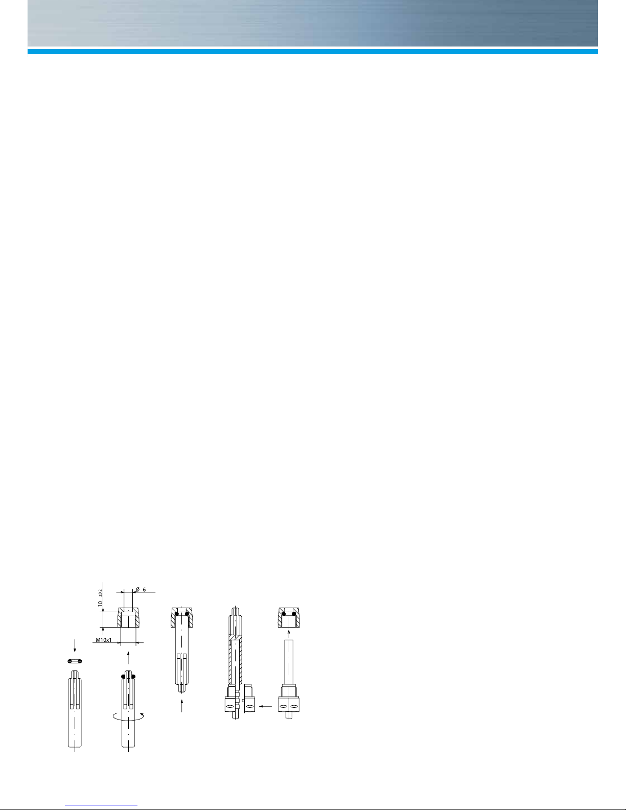
Installing the temperature sensor
■ The installation of the temperature sensors
should be preferably symmetrical and direct
installation.
■ Do not remove the return sensor if already
mounted in the VMU.This is also valid for all
the safety seals which are mounted on the de-
vice as standard.
■ Sensors are colour-coded (red = supply, blue
= return).
■ The connecting cables may not be buckled, ex-
tended or shortened.
■ The seal at the sensor installation point on the
measuring capsule may not be damaged.
■ Remove locking screw and seal at the ball
valve completely, if existing.
■ Attach the O-ring to the installation aid (the 2nd
O-ring is only a spare O-ring).
■ Using the installation aid, insert the O-ring into
the installation point according to DIN EN 1434
with a slight circular motion.
■ Using the other end of the installation aid bring
the O-ring into the correct position.
■ Insert the 2 halves of the plastic connector into
the sensor’s three notches (crimps) and press
them together.
■ Use the installation aid as positioning aid.
■ Insert the temperature sensor into the installa-
tion point and screw it in tightly until the dead
stop of the seal on the 12-point is reached
(mounting torque 3-5 Nm).
■ The sensor optional integrated in the VMT has
to be secured
■ Secure the sensor after installation against
unauthorised removal with appropriate sealing
(available as a sealing set).
Montage DF- Adapter
Page 8

8
Putting into use
■ Open valves carefully and check installation for
leakage.
■ If the sleep mode of the counter is enabled
(Display: SLEEP 1), then it must be deactivat-
ed by longer pressing the button (>5s).
■ While the system is operating, check whether
the volume display advances and the tem-
peratures displayed correspond with the actual
temperatures (see the display overview).
■ Wait for the temperature display to be updated
(1-2 sec).
■ Secure meter with the enclosed sealing mate-
rial against unauthorised removal.
■ Fill in the putting into use report in accordance
with PTB-Directive TR K9.
Consumer
Asymmetrical sensor installation for zelsius® C5-ISF with the return
sensor integrated in the flow sensor
Supply
Return
Consumer
Asymmetrical sensor installation for zelsius® C5-ISF with the return
sensor integrated in the flow sensor
Supply
Return
Consumer
Symmetrical sensor installation for zelsius® C5-ISF
Supply
Return
Note relating to the mounting in existing immersion sleeves:
The device C5 can be put into use in connection
with existing immersion sleeves in accordance
with the article “Putting into use of MID homolo-
gated temperature sensors” released in the PTB
notications 119 (2009), vol.6.
Based on current information, the regulation has
a period of validity until 30.10.2016. For the iden-
tication
and marking of the usable existing immersion
sleeves in connection with the C5 device, an
identication and marking set can be delivered
from our company.
Page 9

9
Status display / Error codes
The symbols in the table below show the meter’s operational status. The status messages only appear in
the main display (energy)! The temporary display of the warning triangle can be caused by special operat-
ing states and does not always mean that the device is malfunctioning. However, should the symbol be
displayed over a longer period of time, you should contact the service company.
Error codes show faults detected by zelsius® C5-ISF. If more than one error appears, the sum of the
error codes is displayed: Error 1005 = error 1000 and error 5.
Code
Error Event
1 Temperature out of measuring range Check sensors
2 Temperature out of measuring range Check sensors
3 Short-circuit return sensor Check sensors
4 Interruption return sensor Check sensors
5 Short-circuit supply sensor Check sensors
6 Interruption supply sensor Check sensors
7 Battery voltage Exchange device
8 Hardware error Exchange device
9 Hardware error Exchange device
100 Hardware error Exchange device
800 Wireless interface Exchange device
1000 Status end of the battery Exchange device respectively battery*
2000 Status Initial verification expired Exchange device
* Due to certification reasons, change of the battery only possible abroad.
Symbol Status Event
External voltage -
Flow existent -
Attention!
Check system / device for errors
Symbol ashing: Data transmission
-
Symbol constantly displayed: optical interface active -
Emergency operation
Exchange device
Page 10

10
Important Note:
The optical interface has to be activated by
means of the OptoHead through keypress before
reading out of the de vice.
Devices, which are in sleep mode (Display:
SLEEP 1) have to be activated through keypress
until the energy display shows up.
Depending on you meter’s model
its displays can differ in number and order from
those shown here.
Ebene 1 Ebene 2
Legend
Press the button briey (S) to switch
through the display from top to bottom.
When you have reached the last menu
item the device automatically jumps back
to the menu item at the top (loop).
Press the button for about 2 seconds (L),
wait for the door symbol to appear (upper
right corner of the display) and then re-
lease the button. The menu is then upda-
ted resp. switches to the sub-menu.
Hold down the button (H) until the device
switches to another level or switches back
from the sub-menu.
A detailed display overview including sub-
menus is available upon request.
H
L
S
Ebene 1 Ebene 2 Ebene 3 Ebene 4
3
4
4
4
3
3
3
3
3
3
3
3
3
3
2
2
2
2
2
2
2
2
2
2
1
1
3
S
S
S
HHH
H
1
3
1
3
1
3
3
3
1
2
3
4
1
1
water-glycol-mixtures*
1
1
1
1
Heat energy
(Main display)
Sensor type and
installation point VMT
Model number
Serial number
Heat energy difference from
last due date to now
Cooling energy difference
from last due date to now
Heat energy difference from
1. this month to now
Cooling energy
Segment test
End of the battery
Error status
System Date
Maximal Flow
Cooling energy difference from
1. this month to now
Volume difference from
1. this month to now
Due date cooling energy
Energy
Last due date
Date last due date
Volume
Supply temperature
Flow rate
System Time
Operation hours
Primary M-Bus address
Date month maximal
flow
Maximum power, Average value
since commissioning
Maximum heat energy
power month
Return temperature
Temperature difference
Certification model
Firmware version
Maximum cooling energy
power month
Maximum cooling energy power,
average value since commissioning
Function
Output 3
Function
Output 2
Function
Output 1
Current output
Pulse value
Input 1
Pulse value
Input 2
Pulse value
Input 3
Ebene 1 Ebene 2 Ebene 3 Ebene 4
3
4
4
4
3
3
3
3
3
3
3
3
3
3
2
2
2
2
2
2
2
2
2
2
1
1
3
* Function only available in variant zelsius C5 „Glycol Meter“
2
S
S
S
HHHH
1
3
1
3
1
3
3
3
1
2
3
4
1
1
water-glycol-mixtures*
1 1
1
1
Heat energy
(Main display)
Sensor type and
installation point VMT
Model number
Serial number
Heat energy difference from
last due date to now
Cooling energy difference
from last due date to now
Heat energy difference from
1. this month to now
Cooling energy
Segment test
End of the battery
Error status
System Date
Maximal Flow
Cooling energy difference from
1. this month to now
Volume difference from
1. this month to now
Due date cooling energy
Energy
Last due date
Date last due date
Volume
Supply temperature
Flow rate
System Time
Operation hours
Primary M-Bus address
Date month maximal
flow
Maximum power, Average value
since commissioning
Maximum heat energy
power month
Return temperature
Temperature difference
Certification model
Firmware version
Maximum cooling energy
power month
Maximum cooling energy power,
average value since commissioning
Function
Output 3
Function
Output 2
Function
Output 1
Opto readout energy
Current output
Pulse value
Input 1
Pulse value
Input 2
Pulse value
Input 3
3
4
4
4
3
3
3
3
3
3
3
3
3
3
2
2
2
2
2
2
2
2
2
2
3
2
S
S
HH
H
1
3
1
3
1
3
3
3
1
1
1
Sensor type and
installation point VMT
Model number
Serial number
Heat energy difference from
last due date to now
Cooling energy difference
from last due date to now
Heat energy difference from
1. this month to now
End of the battery
Error status
System Date
Maximal Flow
Cooling energy difference from
1. this month to now
Volume difference from
1. this month to now
System Time
Operation hours
Primary M-Bus address
Date month maximal
flow
Maximum power, Average value
since commissioning
Maximum heat energy
power month
Certification model
Firmware version
Maximum cooling energy
power month
Maximum cooling energy power,
average value since commissioning
Function
Output 3
Function
Output 2
Function
Output 1
Pulse value
Input 1
Pulse value
Input 2
Pulse value
Input 3
Page 11

11
Ebene 3
Level 1
Ebene 4 Setting of water-glycol-mixtures
for zelsius C5 „Glycol Meter“
Selection of the display „E 0“
on Level 1
Press the button for about 2
seconds until letter „E“ ashes
With each short press on the
button the following loop for dif-
ferent mixing ratios runs:
E 20 - E 25 - E 30 - E 35 - E 40 - E 45 - E 50
P 20 - P 25 - P 30 - P 35 - P 40 - P 45 - P 50 - E 0
E = ethylene glycol
P = propylene glycol
E 0 = water without glycol additive
Upon reaching the required value, press the but-
ton for about 2 seconds to program the value.
Buchstabe Letter "E" or "P" will stop ashing.
The programming process can be retried if nec-
essary.
4
4
4
S
H
1
3
1
3
1
3
Pulse value
Input 1
Pulse value
Input 2
Pulse value
Input 3
3
4
4
4
3
3
3
3
3
3
3
3
3
3
2
2
2
2
2
2
2
2
2
2
3
2
S
S
HHHH
1
3
1
3
1
3
3
3
1
1
1
Sensor type and
installation point VMT
Model number
Serial number
Heat energy difference from
last due date to now
Cooling energy difference
from last due date to now
Heat energy difference from
1. this month to now
End of the battery
Error status
System Date
Maximal Flow
Cooling energy difference from
1. this month to now
Volume difference from
1. this month to now
System Time
Operation hours
Primary M-Bus address
Date month maximal
flow
Maximum power, Average value
since commissioning
Maximum heat energy
power month
Certification model
Firmware version
Maximum cooling energy
power month
Maximum cooling energy power,
average value since commissioning
Function
Output 3
Function
Output 2
Function
Output 1
Pulse value
Input 1
Pulse value
Input 2
Pulse value
Input 3
3
4
4
4
3
3
3
3
3
3
3
3
3
3
3
2
S
S
H
H
1
3
1
3
1
3
3
3
Sensor type and
installation point VMT
Model number
Serial number
End of the battery
Error status
System Date
System Time
Operation hours
Primary M-Bus address
Certification model
Firmware version
Function
Output 3
Function
Output 2
Function
Output 1
Opto readout energy
Pulse value
Input 1
Pulse value
Input 2
Pulse value
Input 3
Page 12

12
Disposal
Attention: This device contains a non-remova-
ble and non-rechargeable lithium battery.
Batteries contain substances, which could harm
the environment and might endanger human
health if not disposed of properly.
To reduce the disposal quantity so as unavoid-
able pollutants from electrical and electronic
equipment in waste, old equipment should be
reused prior or materials recycled or reused as
another form.
This is only possible if old equipment, which con-
tains batteries or other accessories are disposed.
Therefore please contact the department of your
local authority which is responsible for waste
disposal. Alternatively a waste disposal via
ZENNER is possible.
Your local or municipal authority or the local
waste disposal company can give you informa-
tion relating the collection points for your used
equipments.
Attention:
Do not dispose of the devices with domestic
waste.
In this way, you will help to protect natural re-
sources and to promote the sustainable reuse
of material resources.
For any question, please contact
info@zenner.com
The most up-to-date information about this prod-
uct and of our installation notice can be found at
www.zenner.com
 Loading...