

Page 1

Colibri 7
Operating Manual
Page 2

ZEI
SS Copyright / Trademark Colibri 7
Knowledge of this manual is required for operation of the device. You should therefore familiarize
yourself with its contents, paying particular attention to instructions concerning safe handling of the
device.
We reserve the right to make changes to the product in the light of technical developments. The manual
is not covered by an update service.
© Unless expressly authorized, dissemination and duplication of this document and commercial
exploitation or communication of its contents are not permitted. Persons in contravention of this
copyright shall be liable for damages.
All rights reserved in the event of granting of patents or registration as a utility model.
ll names of companies and products mentioned in this operating manual may be trademarks or
A
registered trademarks. Third party products are cited for information purposes only. This does not
represent approval or recommendation of these products.
Carl Zeiss Microscopy GmbH accepts no liability for the performance or use of these products.
authorized dealer:
Pulch + Lorenz microscopy
Am Untergrün 23, D-79232 March
tel: 07665 9272-0
fax: 07665 9272-20
mail: kontakt@pulchlorenz.de
web: pulchlorenz.de
Editor: Carl Zeiss Microscopy GmbH
Carl-Zeiss-Promenade 10
07745 Jena, Germany
microscopy@zeiss.com
www.zeiss.com/microscopy
C
arl Zeiss Microscopy GmbH
Königsallee 9-21
37081 Göttingen, Germany
perating manual number: 423052-7344-001
O
Date of publication: Version 5 – 20.02.2017
2 423052-7344-001 02/2017
Page 3

Colibri 7
Contents ZEISS
CONTENTS
Page
1 INTRODUCTION ................................................................................................................ 5
1.1 Notes on device safety ........................................................................................................ 5
1.2 Warning labels ................................................................................................................... 8
1.3 Warranty notes................................................................................................................... 9
2 DESCRIPTION OF THE DEVICE ........................................................................................ 10
2.1 Name, intended use, and main features ............................................................................ 10
2.2 Components overview ...................................................................................................... 11
2.3 Technical data .................................................................................................................. 12
2.4 Operating and function controls ....................................................................................... 13
2.4.1 Connection panel on the lamp module ............................................................................. 13
2.4.2 LED Trigger Box for Colibri 7 (optional) .............................................................................. 14
2.4.3 Control panel for Colibri 7 (optional) ................................................................................. 15
3 START-UP ....................................................................................................................... 17
3.1 Terminal diagrams ............................................................................................................ 17
3.1.1 Terminal diagram for stand-alone operation ...................................................................... 17
3.1.2 Terminal diagram with PC and motorized microscope ........................................................ 18
3.2 Unpacking Colibri 7 .......................................................................................................... 19
3.3 Attaching Colibri 7 to the microscope and connecting it .................................................... 19
3.4 Configuring Colibri 7 with MicroToolBox (MTB) ................................................................. 21
4 OPERATION .................................................................................................................... 23
4.1 Starting operation of Colibri 7 for the first time ................................................................. 23
4.2 Controlling the Colibri 7 solid-state light source................................................................. 23
4.2.1 Control via TFT display of the microscope .......................................................................... 24
4.2.2 Control via the control panel for Colibri 7 .......................................................................... 25
4.2.3 Operation with PC via the ZEN 2.3 (blue edition) software ................................................. 27
5 CARE AND SERVICE ........................................................................................................ 32
5.1 Care ................................................................................................................................. 32
5.2 Service ............................................................................................................................. 33
6 ANNEX ............................................................................................................................ 34
6.1 Property rights .................................................................................................................. 34
02/2017 423052-7344-001 3
Page 4

ZEI
SS List of illustrations Colibri 7
LIST OF ILLUSTRATIONS
Fig. 1 Warning labels on the lamp module .................................................................................... 8
Fig. 2 Warning label on reflected light mount of microscope .......................................................... 9
Fig. 3 Components overview of the Colibri 7 solid-state light source ............................................ 11
Fig. 4 Connection panel on the lamp module .............................................................................. 13
Fig. 5 LED Trigger Box for Colibri 7 (front and rear side) ............................................................... 14
Fig. 6 Control panel for Colibri 7 – operating and function controls ............................................. 15
Fig. 7 Terminal diagram for stand-alone operation ....................................................................... 17
Fig. 8 Terminal diagram with PC and motorized microscope for fast acquisition............................ 18
Fig. 9 Attaching the lamp module to the microscope ................................................................... 19
Fig. 10 Connecting the lamp module and components .................................................................. 20
Fig. 11 MTB – Configuring the connection type ............................................................................. 21
Fig. 12 MTB – Configuring the lamp module type .......................................................................... 22
Fig. 13 TFT display, page "Colibri LEDs": one LED switched on and activated for brightness
adjustment ....................................................................................................................... 24
Fig. 14 TFT display, page "Colibri LEDs": three LEDs switched on and activated for brightness
adjustment ....................................................................................................................... 24
Fig. 15 Control panel for Colibri 7 ................................................................................................. 25
Fig. 16 Colibri 7 control via "Microscope Components" tool.......................................................... 27
Fig. 17 Control menu for Colibri 7 ................................................................................................ 27
Fig. 18 "Locate" tab – "Camera" tool .......................................................................................... 28
Fig. 19 Colibri 7 control via "Channels" tool ................................................................................. 29
Fig. 20 "Acquisition" tab – "Acquisition mode" tool ..................................................................... 30
Fig. 21 Colibri 7 control via "Imaging Setup" tool ......................................................................... 31
4 423052-7344-001 02/2017
Page 5

INTRODUCTION
ly be removed by
ZEISS Service (not a customer interface). Otherwise there is a risk of eye damage upon laser
Colibri 7 Notes on device safety ZEISS
1 INTRODUCTION
1.1 Notes on device safety
The Colibri 7 solid-sate light source has been designed, produced and tested in compliance with the
European standard DIN EN 61010-1 (IEC 61010-1), "Safety requirements for electrical equipment for
measurement, control and laboratory use", meets the requirements set forth in the RoHS Directive
2011/65/EC and carries the mark.
The Colibri 7 solid-state light source meets the Low Voltage Directive 2014/35/EU and the EMC Directive
2014/30/EC.
The devices must be disposed of in compliance with the WEEE Directive 2012/19/EC.
This operating manual contains information and warnings that must be followed by the operator.
The following warning and information symbols are used in this operating manual:
CAUTION
This symbol indicates a potential hazard to the user.
CAUTION LED radiation!
LED risk group 3 according to DIN EN 62471:2009 when the user looks directly into the
Colibri 7 light output.
UV radiation is emitted.
Any direct looking into the Colibri 7 light output is to be avoided.
Failure to heed this caution may result in eye damage.
Skin and eye irradiation is to be minimized by appropriate shielding.
WARNING of possible laser radiation!
The safety screw for fastening the lamp module to the microscope may on
coupling.
CAUTION: High-energy UV radiation!
Risk of damage to the eyes and skin!
CAUTION
Disconnect the device from the line before any intervention!
CAUTION
Hot surfaces on lamp module!
ATTENTION
This symbol indicates a potential hazard to the instrument or system.
NOTE
This symbol designates information that should be closely followed.
02/2017 423052-7344-001 5
Page 6

INTRODUCTION
other applications of the instrument, including the use of individual modules or components.
This also applies to any service or repair work that is not carried out by authorized service
state light source in connection with the
Keep combustible and easily inflammable materials away from the light beam and its
7 is not equipped with any special devices for protection from substances that are
radioactive or other substances that may be
hazardous to health. Observe all legal regulations, particularly the relevant national accident
ZEISS Notes on device safety Colibri 7
Depending on the design of the microscope, the risk for the user must be assessed as being markedly
lower.
When it comes to the intended use of the Axio Observer microscope with Colibri 7, for example, the risk
status of the overall system is downgraded to LED risk group 2 according to DIN EN 62471:2009.
Colibri 7 and its original accessories may only be used for the purposes described in this operating
manual.
Particular attention should be paid to the following:
Use Colibri 7 for ZEISS microscopes only. The manufacturer cannot assume any liability for any
personnel. Failure to comply with this shall render all warranty claims invalid.
To ensure safe operation of the Colibri 7 solidmicroscope, pay attention to the operating manual of the microscope.
Colibri 7 is not to be used in explosive environments.
surroundings.
Colibri
corrosive, potentially infectious, toxic, and
prevention regulations when handling such substances.
Disconnect the power plug of the desktop power supply unit prior to assembly / disassembly of
the lamp module.
Only specially authorized experts or service staff are permitted to open the lamp module.
6 423052-7344-001 02/2017
Page 7

INTRODUCTION
to 60 Hz range without the voltage setting on the
The desktop power supply unit should not be brought into contact with moisture. If the
The power plug of the desktop power supply unit must be inserted in an outlet featuring a
grounding (earth) contact. The protective capacity must not be rendered ineffective by the use
detachable power cables with power cables that do not meet the
If it is determined that protective measures are no longer effective, the instrument must be
against inadvertent operation. To repair the instrument,
) or your local ZEISS overseas
cause burns to the eyes and skin. Never look directly into the light and avoid direct skin
devices belonging to the
neither with nor without optical instruments, even not if you
simply want to observe the specimen. Failure to follow these instructions may result in eye
Colibri 7 Notes on device safety ZEISS
The desktop power supply unit of the Colibri 7 solid-state light source permits mains voltages in
the 100 V to 240 V ±10 %, 50 Hz
instrument having to be changed.
housing is damaged, the desktop power supply unit should be taken out of use. Colibri 7 must
only be operated with the desktop power supply unit contained in the scope of delivery.
Before connecting the desktop power supply unit to a power outlet check whether it is suitable
for the available line voltage.
of extension cables with no grounding conductor.
Do not substitute
specifications. Only the specified power cables should be used.
taken out of service and secured
contact the ZEISS service team in Germany (see page 33
representative.
Colibri 7, if equipped with the corresponding LED modules, emits ultraviolet radiation that may
exposure. When operating the microscope, always use the protective
instrument.
Never look into the light beam –
injury!
Take appropriate protective measures if the specimen releases noxious gases, dust, and vapors,
secondary radiation or explosive substances as a result of the UV radiation!
Hot surfaces on lamp module! Avoid touching the hot lamp housing.
02/2017 423052-7344-001 7
Page 8
INTRODUCTION
that may damage the device and, in extreme cases, cause a fire. Always keep the ventilation
protected from these influences and covered with the dust cover when not being in use.
Defective devices must not be disposed of with the household waste. Dispose them of in
compliance with the relevant legal requirements or return them to the manufacturer of the
ZEISS Warning labels Colibri 7
Placing objects against or covering ventilation slats of the control unit may lead to heat build-up
slots clear and ensure that no objects enter or fall into the instrument through the ventilation
slats.
Dust and dirt may impair the instrument’s performance. Therefore, the device must largely be
Always check whether the instrument is switched off before you cover it.
device.
The manufacturer of the device is under the legal obligation to take defective devices back.
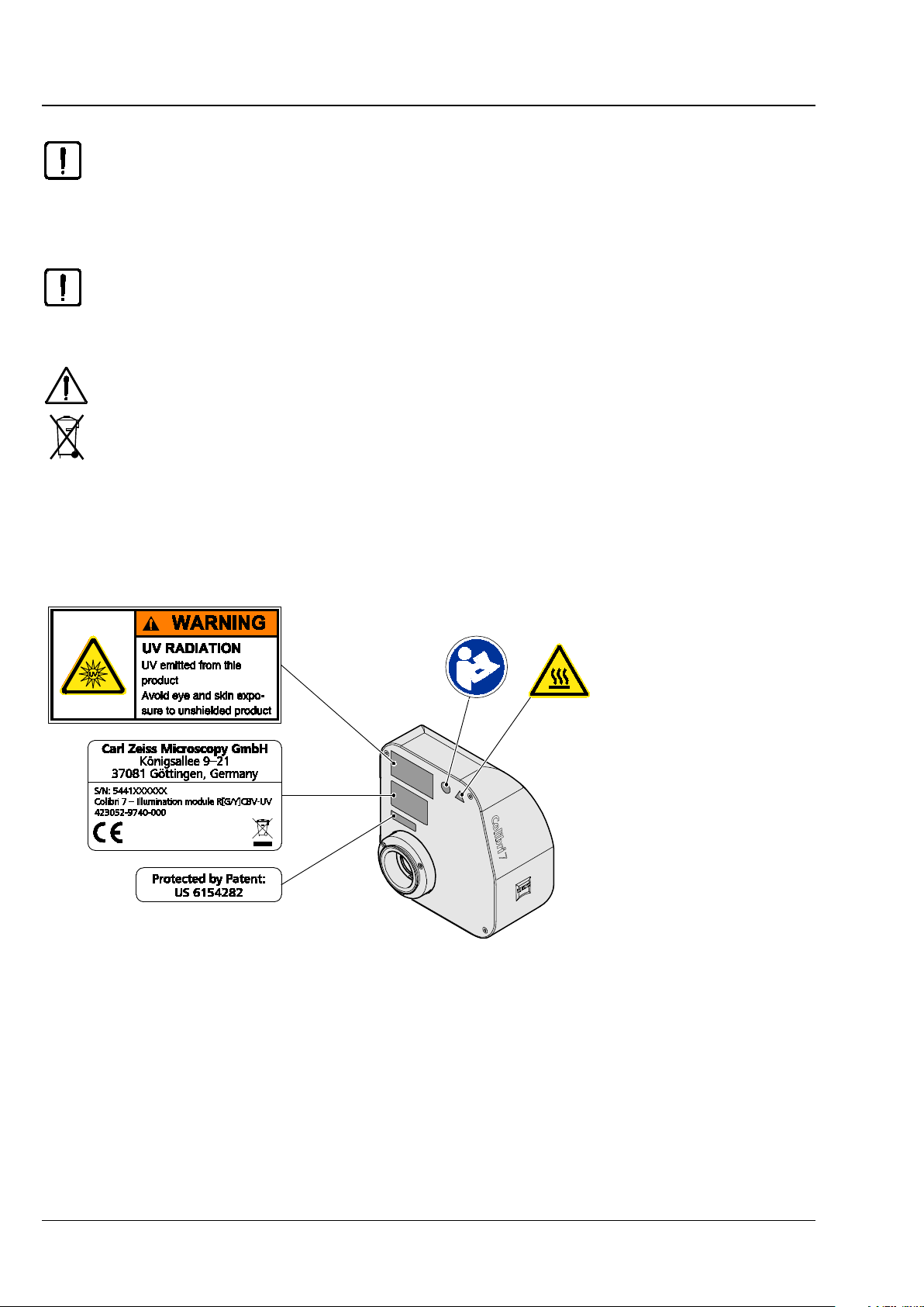
1.2 Warning labels
Standard labeling
Fig. 1 Warning labels on the lamp module
8 423052-7344-001 02/2017
Page 9

INTRODUCTION
fastening the lamp module to the
microscope may only be removed by ZEISS Service (not a customer interface). Otherwise there is
Colibri 7 Warranty notes ZEISS
Labels on the reflected light mount of the microscope for laser application with Colibri 7
Fig. 2 Warning label on reflected light mount of microscope
The safety screw (Fig. 2
/1) on the reflected light mount for
a risk of eye damage upon laser coupling.
1.3 Warranty notes
The manufacturer guarantees that the device is free of material or manufacturing defects upon delivery.
Any defects must be reported immediately and steps taken to minimize damage. If such a defect is
reported, the device manufacturer shall be obliged to correct the default, either by repairing the device or
replacing it with a new one, at the manufacturer’s discretion. No warranty is given for defects caused by
natural wear (particularly of wearing parts) and improper use of the device.
The device manufacturer shall not be liable for damage caused by misuse, negligence or any other
tampering with the device, particularly the removal or replacement of instrument components, or the use
of accessories from other manufacturers. Such actions shall invalidate any warranty claims.
With the exception of the work described in this manual, no maintenance or repair work is to be carried
out on these microscopes. Repairs may only be carried out by ZEISS Service or individuals specially
authorized by ZEISS Service. In the event of a problem occurring with the instrument, please contact the
ZEISS Service in Germany (see page 33) or your local ZEISS overseas representative.
02/2017 423052-7344-001 9
Page 10

DESCRIPTION OF THE DEVICE
ZEISS Name, intended use, and main features Colibri 7
2 DESCRIPTION OF THE DEVICE
2.1 Name, intended use, and main features
Manufacturer’s designation: Colibri 7
Colibri 7 is designed to be used as a light source for reflected light fluorescence applications.
It can be used in connection with the following upright microscopes:
− Axio Imager
− Axio Examiner
− Axioplan 2
− Axioskop 2
− Axioskop 2 FS
− Axioskop 40
− Axio Scope.A1
and with the following inverted microscope:
− Axio Observer
− Axio Vert.A1
− Axiovert 200
The device has the following essential features:
− High-end LED light source for fluorescence applications with visible and UV light for direct
connection to the microscope, no adjustment necessary
− Four different variations (fixed LEDs), equipped with four to seven excitation lines with different
emission wavelengths and fixed excitation filters
− LED emission is individually adjustable for each LED in increments of 1 % (1 – 100 %)
− Standby mode to reduce power consumption
− Real-time stabilization of brightness for low-noise image captures
− Long-time stabilization and performance optimization to improve the comparability of image
captures
− Integrated and motorized switchable excitation filters
− Calibrated and monitored lamp intensity to improve quantification of image results
− Very quick switching on, over and off of the LED modules, no shutter required
− Control via the TFT display of Axio Observer 7 / Z1 stands via CAN connector
− Optional control via software ZEN 2.3 (blue edition), manual control panel or Trigger Box
− Integrated interface for triggered image capture from ZEN 2.3 (blue edition)
− Specific filter sets (as P&C filter modules without excitation filters) for the LED variations deliverable
− Minimum heat development
− Guaranteed lifetime 15,000 h for each bulb per LED line
− Easy integration in 3rd party software packages via LED Trigger Box
10 423052-7344-001 02/2017
Page 11

DESCRIPTION OF THE DEVICE
Colibri 7 Components overview ZEISS
2.2 Components overview
Fig. 3 Components overview of the Colibri 7 solid-state light source
02/2017 423052-7344-001 11
Page 12

DESCRIPTION OF THE DEVICE
ZEISS Technical data Colibri 7
2.3 Technical data
Dimensions
Lamp module (length × width × height) ..................................................... 167 mm x 183 mm x 103 mm
LED Trigger Box (length × width × height) .................................................. 220 mm x 245 mm x 105 mm
Control panel (length × width × height) ....................................................... 180 mm x 110 mm x 70 mm
Weight
Lamp module .................................................................................................................... up to 1,900 g
LED Trigger Box ..............................................................................................................approx. 2,100 g
Control panel .................................................................................................................... approx. 590 g
Excitation wavelengths
Solid-state light source Colibri 7, type RGB-UV ..................................................... 630, 555, 475, 385 nm
Solid-state light source Colibri 7, type RYB-UV ..................................................... 630, 590, 475, 385 nm
Solid-state light source Colibri 7, type R[G/Y]B-UV .........................................630, 590, 555, 475, 385 nm
Solid-state light source Colibri 7, type R[G/Y]CBV-UV .................... 630, 590, 555, 511, 475, 430, 385 nm
Ambient conditions
Transport (in packaging):
Permissible ambient temperature ............................................................................... -40 °C to +70 °C
Storage:
Permissible ambient temperature .............................................................................. +10 °C to +40 °C
Permissible relative air humidity (no condensation) ............................................... max. 75 % at 35 °C
Operation:
Permissible ambient temperature .............................................................................. +10 °C to +40 °C
Permissible relative air humidity (no condensation) ............................................... max. 75 % at 35 °C
Altitude of operating site ................................................................................................ max. 2000 m
Atmospheric pressure ......................................................................................... 800 hPa to 1060 hPa
Degree of pollution ........................................................................................................................... 2
12 423052-7344-001 02/2017
Page 13

DESCRIPTION OF THE DEVICE
module
Colibri 7 Operating and function controls ZEISS
Operating data
Operating area ............................................................................................................... Enclosed rooms
Protection class ......................................................................................................................................I
Ingress protection rating .................................................................................................................. IP 20
Electrical safety ........................................................... in compliance with DIN EN 61010-1 (IEC 61010-1)
............................................................................................. and conforming to CSA and UL regulations
Overvoltage category ............................................................................................................................. II
Radio interference suppression ........................................................ in compliance with EN 55011 Class B
Noise immunity ............................................................................... in accordance with DIN EN 61326-1
Line voltage of controller module ..................................................................... 100 to 240 VAC (±10 %)
Line frequency ...................................................................................................................... 50 to 60 Hz
Power consumption of controller module ....................................................................................... 70 VA
Colibri 7 overall LED classification ........................... LED risk group 3 according to DIN EN 62471:2009
Solid-state light source Colibri 7, type RGB-UV ............. LED risk group 3 according to DIN EN 62471:2009
Solid-state light source Colibri 7, type RYB-UV .............. LED risk group 3 according to DIN EN 62471:2009
Solid-state light source Colibri 7, type R[G/Y]B-UV ........ LED risk group 3 according to DIN EN 62471:2009
Solid-state light source Colibri 7, type R[G/Y]CBV-UV .... LED risk group 3 according to DIN EN 62471:2009
2.4 Operating and function controls
2.4.1 Connection panel on the lamp module
The following connectors are located on the lamp
module (Fig. 4):
1 Increment connection socket
2 USB connection socket
3 Remote connection socket
4 Breakout connection socket
5 Power connection socket
6 CAN connection socket
Fig. 4 Connection panel on the lamp
02/2017 423052-7344-001 13
Page 14

DESCRIPTION OF THE DEVICE
ZEISS Operating and function controls Colibri 7
2.4.2 LED Trigger Box for Colibri 7 (optional)
The LED Trigger Box is only needed if Colibri 7 is to
be controlled via a third-party software.
The front of the LED Trigger Box contains the
following elements (Fig. 5):
1 Power indicator light
2 Digital off / on selection button
3 6x trigger sockets (Digital In) for the LEDs to
be switched: UV, V, B, C, G/Y, R
4 Filter socket
5 Reserve socket
6 6x trigger sockets (Analog In) for the LEDs
to be switched: UV, V, B, C, G/Y, R
7 Analog off / on selection button
The rear of the LED Trigger Box contains the
following elements (Fig. 5):
Fig. 5 LED Trigger Box for Colibri 7 (front
and rear side)
8 Output of connection cable to Colibri 7
(to Breakout connection socket)
Function and description of the selection buttons and trigger sockets
Selection buttons
Digital: on The LED can only be switched on via the trigger sockets (Fig. 5/3).
Digital: off
Analog: on The LED intensity can only be adjusted via the trigger sockets (Fig. 5/6).
Analog: off
Trigger sockets
Digital In
Analog In
The LED can only be switched on via the control panel or the CAN interface.
The LED intensity can only be adjusted via the control panel or the CAN interface.
TTL level
0 to 10 V
14 423052-7344-001 02/2017
Page 15

DESCRIPTION OF THE DEVICE
operating and function controls
Colibri 7 Operating and function controls ZEISS
2.4.3 Control panel for Colibri 7 (optional)
The control panel has the following operating and
function controls (Fig. 6):
1 Control dial for brightness with pushbutton
to select the LED to be controlled
2 Settings button
3 Standby button
4 Shutter button
5 Brightness control of all activated LEDs
switched on button
6 Display
UV LED button for wavelength 385 nm
V LED button for wavelength 430 nm
B LED button for wavelength 475 nm
C LED button for wavelength 511 nm
G LED button for wavelength 555 nm
Y LED button for wavelength 590 nm
Fig. 6 Control panel for Colibri 7 –
R LED button for wavelength 630 nm
Functions of the control panel
Display / control element Function Description
Display
LED buttons
Control dial
Status display of LEDs or of
the device
Switching one or several LEDs
on or off
Rotating function: Brightness
control
Push function: Selecting the
LEDs to be controlled
− On / off state of LEDs
− Current brightness value of the switched
on LEDs in %
− Highlighting of controllable LEDs
− Error messages
LED on: LED button lights up
LED off: LED does not light up
Using the 7 LED buttons, up to 6 LEDs can be
switched on simultaneously.
Control from dark to bright in steps of 1 % to
100 %
− Transit switching between switched-on
LEDs to activate for brightness control.
− A maximum of 6 LEDs can be switched on
simultaneously so that up to 6 LEDs can be
switched through.
− The LED which is currently controlled
flashes.
02/2017 423052-7344-001 15
Page 16

DESCRIPTION OF THE DEVICE
ZEISS Operating and function controls Colibri 7
Display / control element Function Description
Settings button
Standby button
Shutter button
Brightness control of all activated
LEDs button
Setting of brightness for
buttons and display
Menu navigation as follows:
− Enable feature:
Press Settings button
− Adjusting brightness:
Turn the control dial
− Exit feature:
Press Settings button
Colibri 7 standby Activate standby:
− Press Standby button
In standby mode, the backlighting of all
buttons will be switched off, only the standby
button will light up.
All LEDs will be switched off.
Exit standby:
− Press Standby button
Switching all LEDs on and off All LEDs (up to 6) will be switched on or off
simultaneously.
Brightness control of all
activated LEDs switched on
Activating all switched-on LEDs for brightness
control
− Control takes place in an adjusted ratio
relative to the wavelengths of the LEDs
− Control:
Rotate the control dial
- Default values of individual
LEDs
20 % after initialization and activation of the
LEDs
- Intensity value memory In Standby mode:
− Set brightness will be stored after switching
off the device, i.e. when the device is
switched on again, the previously selected
value will be restored.
After deenergizing the device:
− Default values are set.
16 423052-7344-001 02/2017
Page 17

START-UP
Colibri 7 Terminal diagrams ZEISS
3 START-UP
The Colibri 7 solid-state light source consists of the following components:
− Colibri 7 lamp module (available in 4 variations, incl. SPU65-102 desktop power supply unit)
− Control panel for Colibri 7 (optional)
− LED Trigger Box for Colibri 7 (optional)
The device can be commissioned by the customer.
The lamp module of the Colibri 7 solid-state light source is delivered completely assembled in accordance
with the equipment ordered (e.g. RGB-UV variation with 4 excitation lines).
3.1 Terminal diagrams
3.1.1 Terminal diagram for stand-alone operation
Fig. 7 Terminal diagram for stand-alone operation
02/2017 423052-7344-001 17
Page 18

START-UP
ZEISS Terminal diagrams Colibri 7
3.1.2 Terminal diagram with PC and motorized microscope
SVB 1 signal distribution box optional, only for fast acquisition
CAN / USB optional:
CAN for control via ZEN 2.3 (blue edition) ZEISS software
USB for control via third-party software
Fig. 8 Terminal diagram with PC and motorized microscope for fast acquisition
18 423052-7344-001 02/2017
Page 19

START-UP
) on the
reflected light mount for fastening the lamp module to the microscope is a safety screw and
k of
Colibri 7 Unpacking Colibri 7 ZEISS
3.2 Unpacking Colibri 7
The lamp module, the desktop power supply unit and other optional accessories are supplied separately
in customary packaging.
• Remove all parts from the packaging.
• Check them for completeness according to the delivery note.
3.3 Attaching Colibri 7 to the microscope and connecting it
The lamp module is operated via the reflected light mount of the microscope.
In case of microscope systems with laser application, the clamping screw (Fig. 9
may only be removed by ZEISS Service (not a customer interface). Otherwise there is a ris
eye damage upon laser coupling.
In case of microscope systems without laser
applications proceed as follows:
• Attach dovetail (Fig. 9/1) of the lamp module
(Fig. 9/2) to the reflected light mount (Fig. 9/3).
• Tighten clamping screw (Fig. 9/4).
The lamp module does not require any adjustment.
Depending on equipment variation, the Colibri 7
can be controlled via the TFT display of the
microscope, the control panel, the LED Trigger Box
or via PC.
/4
Fig. 9 Attaching the lamp module to the
microscope
02/2017 423052-7344-001 19
Page 20

START-UP
ZEISS Attaching Colibri 7 to the microscope and connecting it Colibri 7
Depending in the existing microscope equipment, ensure the correct connection type as follows:
• Connect the connection cable of the desktop power supply unit (Fig. 10/7) to the Power connection
socket (Fig. 10/5) of the lamp module (Fig. 10/1).
• If used, connect the control panel (Fig. 10/8) with connecting cable to the Remote connection socket
(Fig. 10/2) of the lamp module.
• If used, connect the LED Trigger Box (Fig. 10/9) with connecting cable to the Breakout connection
socket (Fig. 10/3) of the lamp module.
• If the microscope has a TFT display, connect the CAN connection socket (Fig. 10/4) of the lamp
module via the CAN cable to the microscope stand.
• If Colibri 7 is to be controlled via a third-party software on the PC, connect the USB connection socket
(Fig. 10/6) of the lamp module via USB cable to the PC.
Fig. 10 Connecting the lamp module and components
20 423052-7344-001 02/2017
Page 21

START-UP
If the installed lamp module has been connected to the PC via the CAN bus of the motorized
1
2
3
4
Colibri 7 Configuring Colibri 7 with MicroToolBox (MTB) ZEISS
3.4 Configuring Colibri 7 with MicroToolBox (MTB)
stand, it will be automatically recognized and registered by the Auto Configuration function.
If Colibri 7 is connected directly to a PC via USB, the connection type and the lamp module type must be
selected manually in the MTB and transferred to the hardware configuration.
Please proceed as follows for manual configuration:
• Start MTB2011 Configuration by double-clicking on the corresponding icon on the desktop.
• Alternatively, launch the program with:
Start -> All programs -> Carl Zeiss -> MTB 2011 – 2.x.x.x -> MTB2011 Configuration
Like other fluorescence illuminators, Colibri 7 will be used in the reflected light path and will be
displayed in the Reflected Light Path directory (Fig. 11/1) of the microscope.
• Select the Reflected Light Path folder (Fig. 11/1) and then Colibri 7 (Fig. 11/2) in the window of the
MTB which will be displayed upon selecting the configuration in the microscope directory (e.g.
Axio Imager.Z2).
• Select the USB connection type (Fig. 11/3) in the selection list under Colibri 7 / Connection / Type:
and click on Check Connection, if required.
• Then click on Apply (Fig. 11/4).
Fig. 11 MTB – Configuring the connection type
02/2017 423052-7344-001 21
Page 22

START-UP
1
2
3
ZEISS Configuring Colibri 7 with MicroToolBox (MTB) Colibri 7
• Click on the lamp module entry in the Colibri directory (Fig. 12/1)
• Select the name of the installed lamp module in the selection window of lamp modules (Fig. 12/2).
• Then click on Apply (Fig. 12/3).
• Finally, click the current configuration (e.g. Motorized Imager Dual Cam) and click on the Write
configuration to hardware button which will appear next to activate the configuration.
• Exit the MTB program.
Fig. 12 MTB – Configuring the lamp module type
22 423052-7344-001 02/2017
Page 23

OPERATION
Colibri 7 Starting operation of Colibri 7 for the first time ZEISS
4 OPERATION
4.1 Starting operation of Colibri 7 for the first time
Colibri 7 does not have a separate on / off switch.
After mounting it to a microscope it only has to be connected to a power outlet.
• Connect the Colibri 7 desktop power supply unit (Fig. 10/7) with a power supply cable to a power
outlet.
After a short initialization time Colibri 7 is ready for operation.
• Switch on the microscope.
• Start the control software used (from ZEN 2.3 (blue edition) or third-party software).
If the control panel or the LED Trigger Box are connected, they will be powered via Colibri 7 and are also
ready for use.
4.2 Controlling the Colibri 7 solid-state light source
Colibri 7 can be controlled in various ways depending on the available components:
− via TFT display and selector wheel for illumination intensity at the Axio Observer, Axio Imager or
Axio Examiner microscopes, see section 4.2.1
− via the control panel for Colibri 7, see section 4.2.2
− via PC and installed software ZEN 2.3 (blue edition), see section 4.2.3
− via LED Trigger Box or external triggering via third-party software
02/2017 423052-7344-001 23
Page 24

OPERATION
Colibri 7 has been mounted on the
microscope, connected via CAN and
powered via the desktop power supply
The G and Y intensity has always an
identical value because the same LED is
activated for brightness adjustment
ZEISS Controlling the Colibri 7 solid-state light source Colibri 7
4.2.1 Control via TFT display of the microscope
unit.
The microscope has been switched on.
• Select the Colibri LEDs page on the TFT display
of the microscope: Press
Microscope -> Control -> Colibri LEDs
(see Fig. 13).
Fig. 13 TFT display, page "Colibri LEDs":
one LED switched on and activated
for brightness adjustment
• Open the shutter in the reflected light path by
clicking the RL Illumination -> On button.
• Switch on the desired LED by shortly pressing
the corresponding button, e.g. UV button.
The button changes its color from blue to gray.
• To activate the LED for brightness adjustment,
press the corresponding button longer.
The marking circle in the upper left of the button
changes to green.
• Set the desired brightness with the selector
wheel on the microscope stand (e.g. on front
side of Axio Observer).
The current brightness adjustment of the LED will
be displayed in percent in the button below the
letter.
Fig. 14 TFT display, page "Colibri LEDs":
three LEDs switched on and
used for both excitation colors.
• To adjust the brightness control of all LEDs switched on simultaneously press the button (sun).
This button will now be gray , and all LEDs switched on are activated and marked with a green circle
(see Fig. 14).
• Set the desired brightness for the LEDs switched on simultaneously using the selector wheel on the
microscope.
In the display field below the LED buttons the wavelength and current brightness settings are displayed
for the selected LED.
24 423052-7344-001 02/2017
Page 25

OPERATION
If the brightness of several LEDs is controlled simultaneously, the LEDs which are switched on
are controlled relative to each other. Thus, various adjustment values may be displayed for the
The remaining LEDs can be
control the intensity of the selected LEDs. To control TL illumination intensity, the RL shutter
Colibri 7 has been mounted on the
microscope and powered via the
desktop power supply unit.
The control panel is connected to the
Colibri 7 Controlling the Colibri 7 solid-state light source ZEISS
LEDs. If an LED reaches 100 % it cannot be set to a higher value.
controlled simultaneously, until they have reached their maximum at 100 %.
If the (sun) button is activated, further LEDs will be automatically controlled when switched
on.
If RL and TL are switched on at the same time, the selector wheel on the microscope stand will
must be closed.
4.2.2 Control via the control panel for Colibri 7
Colibri 7.
The microscope has been switched on.
• Open the reflected light path shutter on the
stand, if required.
• Switch on the desired LED by shortly pressing
the corresponding LED button (see Fig. 15/5),
e.g. UV LED button.
The LED button lights up. On the display
(Fig. 15/1), the current brightness value is shown as
a percentage to signal that the LED is switched on.
• If required, switch on further LEDs by pressing the corresponding LED buttons (up to 6 LEDs
Fig. 15 Control panel for Colibri 7
simultaneously).
• Activate the brightness adjustment for an LED by pressing the control dial (Fig. 15/6) shortly
downwards.
The LED which is switched on and activated for brightness adjustment will flash. The LED which has been
activated for brightness adjustment will be marked with a circle (Fig. 15/2) left of the letter.
• If several LEDs have been switched on, press the control dial shortly until the LED button of the desired
LED flashes. The LEDs which are switched on can be switched through by shortly pressing the control
dial.
• Set the desired brightness for the activated LEDs using the control dial on the control panel.
The brightness setting is updated synchronously on the display.
• To adjust the brightness control of all LEDs switched on simultaneously press the button
(Fig. 15/4).
All LEDs which are switched on will flash.
02/2017 423052-7344-001 25
Page 26

OPERATION
ZEISS Controlling the Colibri 7 solid-state light source Colibri 7
• Use the control dial to set the brightness for the activated LEDs simultaneously.
If the brightness adjustment of several LEDs is controlled simultaneously, the LEDs which are switched on
are controlled relative to each other. Thus, various adjustment values may be displayed for the LEDs. If an
LED reaches 100 % it cannot be set to a higher value. The remaining LEDs can be controlled
simultaneously, until they have reached their maximum at 100 %. When decreasing the brightness, the
brightness of all LEDs will be decreased in reverse order.
• To quickly switch on and off all LEDs switched on simultaneously press the button (Fig. 15/3).
• To activate / deactivate the standby mode press the button (Fig. 15/8).
• To change the brightness of buttons and display press the button (Fig. 15/7) and set the desired
brightness using the control dial. To finish the setting, press the button again.
26 423052-7344-001 02/2017
Page 27

OPERATION
Colibri 7 has been mounted on the
microscope, connected via CAN and
powered via the desktop power supply
e and the PC have been
After opening, the default mode of the
Colibri 7 Controlling the Colibri 7 solid-state light source ZEISS
4.2.3 Operation with PC via the ZEN 2.3 (blue edition) software
unit.
The microscop
switched on.
The ZEN software (blue edition) has
been started.
4.2.3.1 Control of Colibri 7 with the "Microscope Control" tool in the "Locate" tab
• Click on the Locate tab in the software (see
Fig. 16).
• Expand the Microscope Control tool by
clicking on the expander.
• If required, activate the Show All option.
• Click on the Colibri 7 icon to open the
Colibri 7 control menu.
control menu is Continuous.
• Switch the LEDs on or off by activating /
deactivating the respective checkbox, e.g.
(see Fig. 17).
• Adjust the brightness for the selected wave
length using the sliders, entry fields or arrow
buttons.
• Activate the excitation filter for LED 567 by
clicking on the 555 or 590 button at Excitation
filter for LED 567.
Fig. 16 Colibri 7 control via "Microscope
Components" tool
• Switch all LEDs simultaneously on or off by
clicking on Deactivate all LEDs or Activate all
LEDs.
• Click on Continuous or Gated to select the
desired mode for image acquisition (see also
next page).
02/2017 423052-7344-001 27
Fig. 17 Control menu for Colibri 7
Page 28

OPERATION
Fig. 18 "Locate" tab – "Camera" tool
ZEISS Controlling the Colibri 7 solid-state light source Colibri 7
Image acquisition in "Continuous" mode in the "Locate" tab
Continuous is the default setting for Colibri 7 in the ZEN 2.3 (blue edition) control software.
When acquiring images with a camera mounted to the microscope system, the corresponding LEDs must
be manually switched on in the Locate tab and switched off again after acquisition.
• Switch on all required LEDs by clicking the corresponding checkbox and set the desired brightness.
• Use the Live, Continuous or Snap buttons to acquire images (see Fig. 16).
• Switch the LEDs off by clicking with the mouse.
Image acquisition in "Gated" mode in the
"Locate" tab
Gated allows the direct control of LEDs via the
trigger output of the camera.
The active LED will be switched on or off with the
adjusted brightness in parallel to camera exposure.
The bleaching impact on the probe will be reduced
by synchronizing the exposure time of Colibri 7
with that of the camera.
• Connect the trigger output of the camera (e.g.
Axiocam 506) using the trigger cable (accessory
for Axiocam, order number 426557-0001-000,
see operating manual Axiocam) with the
Increment outlet socket on Colibri 7 (see
(Fig. 4/1).
• In the Locate tab, expand the Camera tool by
clicking on the expander (see Fig. 18).
• Activate the checkboxes Enable for Snap and
Enable for Live in Trigger Control -> Trigger
Out (see Fig. 18)
• Activate the Gated mode in the Colibri 7
control menu (see Fig. 17).
• Select the LEDs by clicking the corresponding
checkbox and set the desired brightness.
The LEDs will only be switched on or off
automatically during image acquisition.
• Open the reflected light shutter of the
microscope.
• Use the Live, Continuous or Snap buttons to
acquire images.
28 423052-7344-001 02/2017
Page 29

OPERATION
Colibri 7 Controlling the Colibri 7 solid-state light source ZEISS
4.2.3.2 Control of Colibri 7 with the "Channels" tool in the "Acquisition" tab
• Click on the Acquisition tab in the software
(see Fig. 19).
• Open the Channels tool by clicking on the
expander .
• Set the channels manually or via Smart Setup.
Alternatively, you can load a saved experiment.
• If required, activate the Show All option.
• If required, select Colibri 7 as light source in
Selected Lightsource.
• Switch the LEDs on or off by activating /
deactivating the respective checkbox, e.g.
.
• Adjust the brightness for the selected wave
length using the sliders, entry fields or arrow
buttons.
• Activate the excitation filter for LED 567 by
clicking on the 555 or 590 button at Excitation
filter for LED 567.
• Select all LEDs simultaneously by clicking on
Deactivate all LEDs or Activate all LEDs.
• Click on Continuous or Gated to select the
desired mode for image acquisition.
Image acquisition in "Continuous" mode in
the "Acquisition" tab
Continuous is the default setting for Colibri 7 in
the ZEN control software.
The camera and Colibri 7 are automatically
controlled via software commands. Manual
switching on or off is not necessary.
Image acquisition during the experiment: The LEDs
are shuttered between exposures via software
commands.
• Select the required LEDs by clicking the
corresponding checkbox and set the desired
brightness.
• Use the Live, Continuous or Snap buttons to
acquire images.
Fig. 19 Colibri 7 control via "Channels" tool
02/2017 423052-7344-001 29
Page 30
OPERATION
ZEISS Controlling the Colibri 7 solid-state light source Colibri 7
Image acquisition in the "Gated" mode
Gated allows the direct control of LEDs via the
trigger output of the camera.
The active LED will be switched on or off with the
adjusted brightness in parallel to camera exposure.
All relevant shutters will be automatically
controlled by ZEN.
The bleaching impact on the probe will be reduced
by synchronizing the exposure time of Colibri 7
with that of the camera.
In an experiment, the Gated mode is typically
faster than the Continuous mode.
• Connect the trigger output of the camera using
the trigger cable (accessory for Axiocam, order
number 426557-0001-000, see operating
manual Axiocam) with the Increment outlet
socket on Colibri 7 (see (Fig. 4/1).
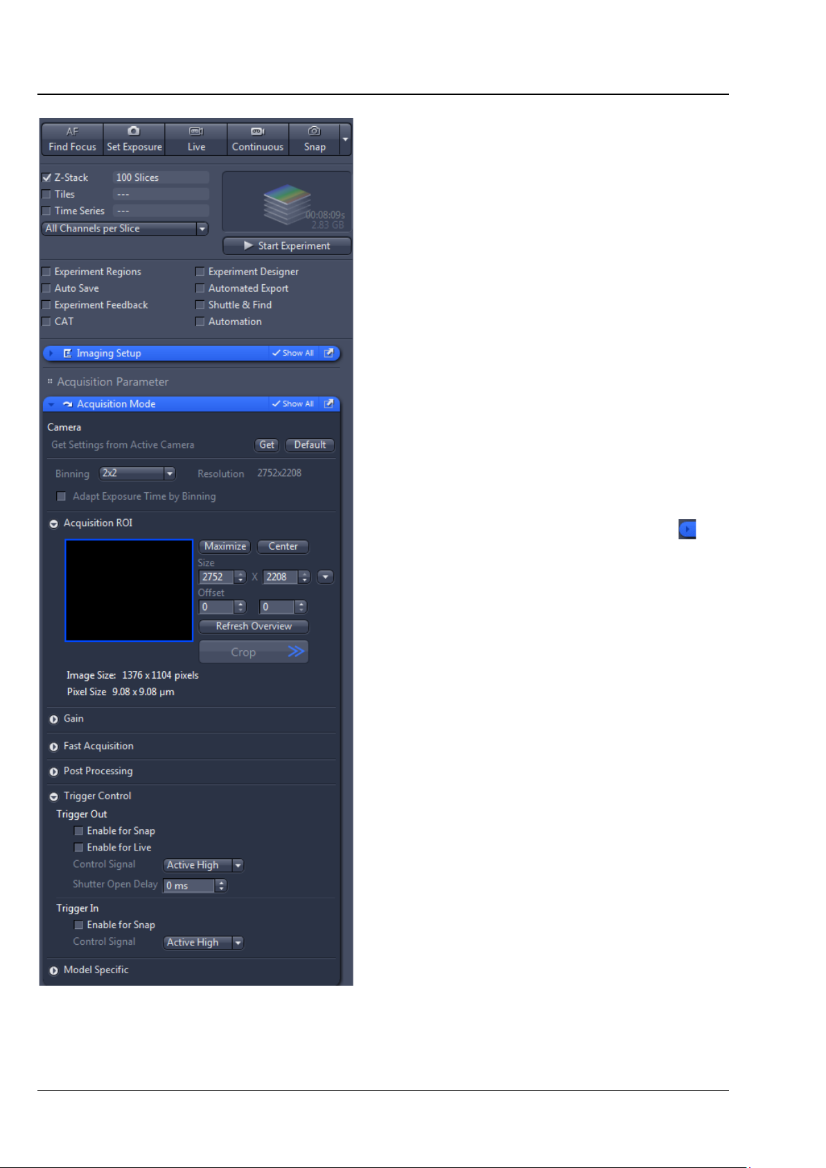
• In the Acquisition tab, expand the Acquisition
mode tool by clicking on the expander (see
Fig. 20).
• Activate the checkboxes Enable for Snap and
Enable for Live in Trigger Control -> Trigger
Out.
• Activate the Gated mode in the Colibri 7
control menu.
• Activate LEDs by clicking the corresponding
checkbox and set the desired brightness.
• Use the Live, Continuous or Snap buttons to
acquire images.
Fig. 20 "Acquisition" tab – "Acquisition
mode" tool
30 423052-7344-001 02/2017
Page 31

OPERATION
Colibri 7 Controlling the Colibri 7 solid-state light source ZEISS
4.2.3.3 Colibri 7 control via "Imaging Setup" tool and including of hardware settings into the "Acquisition" tab
The control of Colibri 7 in the Imaging Setup tool
of the Acquisition tab is analogous to the
Microscope Control tool.
Additionally, the switching states of LEDs and the
image acquisition mode can be saved here by
clicking the check boxes in the Include in this
Setting... field (Fig. 21).
Fig. 21 Colibri 7 control via "Imaging
Setup" tool
02/2017 423052-7344-001 31
Page 32

CARE AND SERVICE
The risk of growth of fungus on opto-mechanical instruments always exists in the following
°C for more than
ZEISS Care Colibri 7
5 CARE AND SERVICE
5.1 Care
Disconnect the power plug of the desktop power supply unit prior to cleaning!
Clean labels and desktop power supply unit only dry.
• Clean lamp module, control panel and LED Trigger Box only with a slightly moist cloth (not dripping
wet). Do not allow moisture to penetrate the inside of the devices.
• All labels on the components and the desktop power supply unit may only be cleaned using a dry
cotton cloth. Do not allow moisture to penetrate the inside of the desktop power supply unit.
When using the device in warm and humid climatic zones, pay attention to the following instructions:
• Store the device in bright, dry and well-ventilated rooms with a humidity of less than 65 %; store
particularly sensitive optical components and accessories, such as objectives and eyepieces, in a dry
cabinet.
• If the microscope is to be stored in closed containers for a prolonged period, fungicide-soaked cloths
should be placed in the containers to prevent mould.
conditions:
− relative humidity > 75 % and temperatures between +15 °C and +35
three days
− installation in poorly-ventilated, dark rooms and
− dust deposits and fingerprints on optical surfaces.
32 423052-7344-001 02/2017
Page 33

CARE AND SERVICE
Colibri 7 Service ZEISS
5.2 Service
Any repairs to optical components or moving parts inside the instrument or any work on the power
supply may only be carried out by service technicians or specially authorized personnel.
f servicing is required, please contact your local representative or
I
Carl Zeiss Microscopy GmbH
Carl-Zeiss-Promenade 10
07745 Jena, Germany
microscopy@zeiss.com
www.zeiss.com/microscopy
arl Zeiss Microscopy GmbH
C
Königsallee 9-21
37081 Göttingen, Germany
02/2017 423052-7344-001 33
Page 34

ANNEX
ZEISS Property rights Colibri 7
6 ANNEX
6.1 Property rights
evices, parts of devices or any procedures described in this manual are protected by the following
D
patents:
S 6154282 A1 Semiconductor based excitation illuminator for fluorescence and phosphorescence
U
microscopy.
authorized dealer:
Pulch + Lorenz microscopy
Am Untergrün 23, D-79232 March
tel: 07665 9272-0
fax: 07665 9272-20
mail: kontakt@pulchlorenz.de
web: pulchlorenz.de
34 423052-7344-001 02/2017
 Loading...