

Page 1

___________________________________________________________________________
Infrastructure Installation Guide
Location Sensor
(including Locating Access Point)
Installation Guide
___________________________________________________________________________ 1
Location Sensor Installation Guide D0405 rev PA6
Copyright WhereNet, Corp. 2001
WhereNet Confidential
Page 2
___________________________________________________________________________
_____________
____________
____________
Infrastructure Installation Guide
Typographical Conventions
Warnings call attention to a procedure or practice that could result in
personal injury if not correctly performed. Do not proceed until you fully
_____________
______________
Note
____________
understand and meet the required conditions.
Cautions call attention to an operation procedure or practice that could
damage the product, or degrade performance if not correctly performed. Do
not proceed until understanding and meeting these required conditions.
Notes provide information that can be helpful in understanding the operation
of the product.
___________________________________________________________________________ 2
Location Sensor Installation Guide D0405 rev PA6
Copyright WhereNet, Corp. 2001
WhereNet Confidential
Page 3

___________________________________________________________________________
Infrastructure Installation Guide
Document Revision History
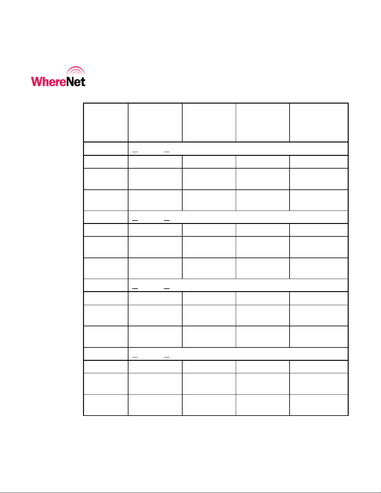
Revision Description of Changes Date Approved
PA6 Preliminary 1/20/02
___________________________________________________________________________ 3
Location Sensor Installation Guide D0405 rev PA6
Copyright WhereNet, Corp. 2001
WhereNet Confidential
Page 4

___________________________________________________________________________
Infrastructure Installation Guide
Table of Contents Page
1 DOCUMENT O VERVIEW 6
2 PRODUCT DESCRIPTION AND FEATURES 6
3 PRODUCT SPECIFICATIONS 8
4 PARTS AND TOOLS 9
5 CONFIGURATION 13
6 ASSEMBLY INSTRUCTIONS 17
7 FCC INFORMATION 17
8 MOUNTING O VERVIEW 19
9 CABLING 23
10 LOCATION SENSOR INSTALLATION CHECKLIST 27
Table of Figures Page
FIGURE 1 ALL WEATHER OMNI ANTE NNA 11
FIGURE 2 INDOOR OFFICE OMNI ANTENNA 11
FIGURE 3 FLAT PANEL DIRECTIONAL ANTENNA 11
FIGURE 4 OPTIONAL HIGH GAIN ANTENNA 11
FIGURE 5 POWER SUPPLY 12
FIGURE 6 OUTDOOR P.S. HOUSING 12
FIGURE 7 RJ CABLE TOOL 13
FIGURE 8 FLUKE LAN CABLEMETER 13
FIGURE 9 LAP-4200 LABEL 15
___________________________________________________________________________ 4
Location Sensor Installation Guide D0405 rev PA6
Copyright WhereNet, Corp. 2001
WhereNet Confidential
Page 5

___________________________________________________________________________
Infrastructure Installation Guide
FIGURE 10 WALL MOUNTING HOLE DIMENSIONS 21
FIGURE 11 LOCATION SENSOR CONNECTIONS 23
FIGURE 12 LOCATION SENSOR LED INDICATORSLED INDICATORS 33
___________________________________________________________________________ 5
Location Sensor Installation Guide D0405 rev PA6
Copyright WhereNet, Corp. 2001
WhereNet Confidential
Page 6

___________________________________________________________________________
Infrastructure Installation Guide
1 DOCUMENT OVERVIEW
This document describes the physical installation and basic configuration of the
Location Sensor product. The site design is detailed in the D0406 Location Sensor
Placement Guide.
2 PRODUCT DESCRIPTION AND FEATURES
The Location Sensor receives the signals transmitted by the WhereTags, which are
attached to the tracked assets. The decoded tag information is time stamped and
routed to a PC for additional processing. The locate algorithm running on the PC
calculates the tag position based on the time stamps of multiple Location Sensors,
and reports that position to the database where it is displayed by Resource
Manager.
There are two separate Location Sensor models:
• LOS-4100 (802.3 Wired Ethernet)
• LAP-4200 (with 802.11b Wireless LAN Access Point, also known as a
Locating Access Point)
The difference between the two models is that the LAP-4200 contains an Access
Point, while the LOS-4100 does not. These units are identical in appearance; the
___________________________________________________________________________ 6
Location Sensor Installation Guide D0405 rev PA6
Copyright WhereNet, Corp. 2001
WhereNet Confidential
Page 7

___________________________________________________________________________
Infrastructure Installation Guide
only way to distinguish them is by the model number on the housing. Note that
both units have a wired Ethernet port; the LAP-4200 has a can function as either a
client bridge or an access point.
Both units also include a low power transmitter which is used to distribute
configuration data, and timing signals to other Location Sensor units. This
transmitter has the same transmitter characteristics as a tag.
Features include:
• Outdoor weatherproof housing
• Wireless data transport capability
• Wireless Timing capability
There are three separate antenna options for the Location Sensor. In addition,
there is an optional high gain Wireless LAN Access Point directional antenna for
installati ons in which the standard antennas do not proved the range required to
communicate with the base access point. The available antennas are listed in
section 4 below.
___________________________________________________________________________ 7
Location Sensor Installation Guide D0405 rev PA6
Copyright WhereNet, Corp. 2001
WhereNet Confidential
Page 8

___________________________________________________________________________
18 to 36
Infrastructure Installation Guide
3 PRODUCT SPECIFICATIONS
3.1 Mechanical
Size: 10.3 x 3.2 x 12.0
261 x 80 x 305
Weight: 8.0
3.6
in (HxDxW)
mm
Lbs
kg
3.2 Electrical
Voltage:
36 nominal
Current: 1.5 (max) Amps
Pwr Diss: 25 (max) Watts
AC Power1
1
With recommended power supply
100- 240 Vac
Vdc
3.3 Environmental
___________________________________________________________________________ 8
Location Sensor Installation Guide D0405 rev PA6
Copyright WhereNet, Corp. 2001
WhereNet Confidential
Operating Temperature:
Storage Temperature:
-30 to +50
-40 to +70
Ingress Protection: 65 IP
ºC
Page 9

___________________________________________________________________________
Infrastructure Installation Guide
3.4 External Connections
Antenna: MCX (female)
DC Power: 2.5 ID/ 5.5 OD mm (female)
Opt. Access Point Antenna: RP-TNC (male)
Ethernet RJ45 (female)
Timing RJH (4 wire telephone handset, female)
4 PARTS AND TOOLS
The parts and tools indicated below are required to complete the installation of the
Location Sensor. Ordering information is supplied where applicable.
Part Model Number
• All Weather Omni Antenna1 (standard)
• Office Omni Antenna1 (indoor only)
• Flat PanelAntenna1 (directional indoor/
AK-210 (Figure 1)
AK-110 (Figure 2)
AK-120 (Figure 3)
outdoor)
• High Gain WLAN Antenna (optional)
• Power Supply
• Outdoor Power Supply enclosure
TBD (Figure 4)
PS-021 (Figure 5)
(Figure 6)
(outdoor use only)
___________________________________________________________________________ 9
Location Sensor Installation Guide D0405 rev PA6
Copyright WhereNet, Corp. 2001
WhereNet Confidential
Page 10

___________________________________________________________________________
Infrastructure Installation Guide
Part Model Number
• Pole Mount Kit
• Wall Mount Bracket (to provide 12
inch (305 mm) spacing from metal
wall w/ AK-210 antenna
• Cat 5 network cable;
• Connector
• Timing cable (2 twisted pairs);
• Connector
• Network hub/ router/ switch
1
Choose 1 of the three antenna options
RM-410-00
RM-250-00
Belden: 1583A 006U1000
riser , 1585A 877U1000
Plenum, or equiv.
1624R Non-plenum, shielded;
1624P Plenum, shielded.
AMP 5-569278-X with load
bar, or AllenTel
AT8X8RCSC-24
Belden: 1588R-006U1000
riser, 1590A-8771000 plenum
Allen Tel AT4X4SC-2224
N/A
Recommended cable/connector/tool supplier Graybar (800) 766-7101
___________________________________________________________________________ 10
Location Sensor Installation Guide D0405 rev PA6
Copyright WhereNet, Corp. 2001
WhereNet Confidential
Page 11
___________________________________________________________________________
Infrastructure Installation Guide
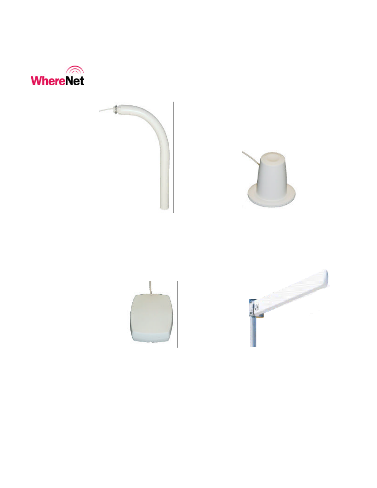
Figure 1 All weather omni antenna Figure 2 Indoor office omni antenna
Figure 3 Flat panel directional antenna Figure 4 Optional high gain antenna
___________________________________________________________________________ 11
Location Sensor Installation Guide D0405 rev PA6
Copyright WhereNet, Corp. 2001
WhereNet Confidential
Page 12

___________________________________________________________________________
Infrastructure Installation Guide
Figure 5 Power supply Figure 6 Outdoor P.S. housing
Tools
• Computer to configure Location
Sensor, including
• Crossover Cat 5 (Ethernet) cable
• Null Modem serial cable (optional)
Available locally
Digi-Key: AE1034-ND DB9
M/F, or AE1033-ND F/F
• RJ Connector tool for RJ45 and RJH
• Fluke 620 LAN CableMeter
• Miscellaneous hand tools
Figure 7
Figure 8
Available locally
___________________________________________________________________________ 12
Location Sensor Installation Guide D0405 rev PA6
Copyright WhereNet, Corp. 2001
WhereNet Confidential
Page 13
___________________________________________________________________________
____________
Infrastructure Installation Guide
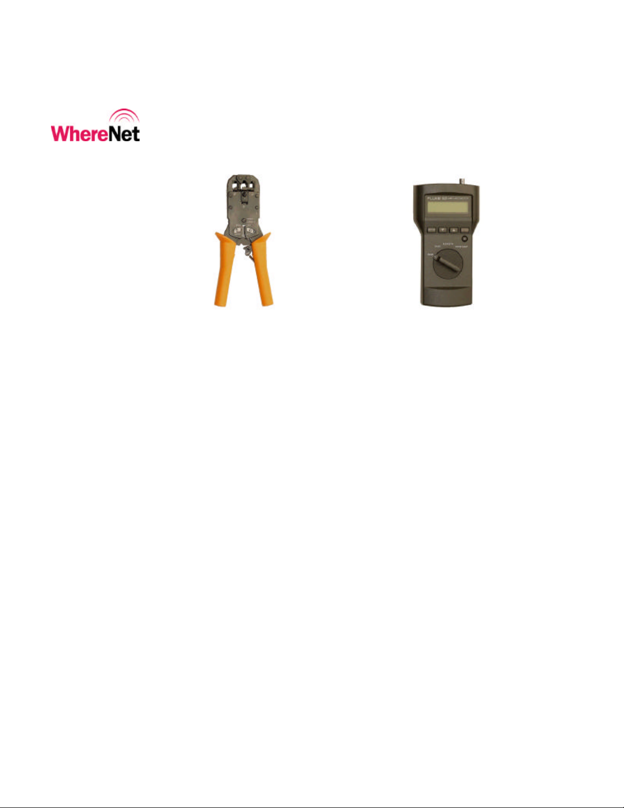
Figure 7 RJ cable tool Figure 8 Fluke LAN CableMeter
Note
____________
5 CONFIGURATION
The Location Sensor (Location Access Point) must be configured prior to
operation. Configuration includes:
• Setting the Location Sensor configuration, including the IP address
• Setting the embedded Access Point configuration (LAP-4200 only),
including the Service Set Identifier (ESS ID), and IP address.
Failure to configure the Location Sensor prior to operation may result in an
inoperative unit.
___________________________________________________________________________ 13
Location Sensor Installation Guide D0405 rev PA6
Copyright WhereNet, Corp. 2001
WhereNet Confidential
Page 14

___________________________________________________________________________
Infrastructure Installation Guide
Both of these units are configured using:
• LPManager software via Ethernet (preferred),
• Telnet via Ethernet, or
• Hyperterminal (or any terminal emulation software) via serial port
For the LAP-4200, both the Location Sensor and the embedded Access Point must
be independently configured. That is, both units must have their IP addresses
correctly specified. The communication connection can be switched between the
Location Sensor and the Access Point by typing ctrl-w.
5.1 Location Sensor Configuration
Location Sensors communicate over an Ethernet interface using TCP/IP. Each
Location sensor must be configured with a unique IP address. The IP address of
each LS must be recoded and entered into the WhereNet site file, which contains
the configuration information for each LS, including its location.
Each Location Sensor is shipped with a label set containing one label (Figure 9)
with the bar coded MAC address of the Location Sensor (and of the Access Point
if so equipped) and three labels with the last six characters of the Location
Sensor’s MAC address in large type. Ensure that the label is correct by matching
the MAC address(es) on the loose label set with the MAC address(es) listed on the
back of the Location Sensor. Place the loose bar code label in the site design
___________________________________________________________________________ 14
Location Sensor Installation Guide D0405 rev PA6
Copyright WhereNet, Corp. 2001
WhereNet Confidential
Page 15

___________________________________________________________________________
Last 6 LS
Access
Point
Label applied
factory
Location Sensor
Location Sensor
Infrastructure Installation Guide
document where indicated, and place one or more of the large type, six character
labels on the exterior of the Location Sensor in positions that are visible after
installation.
MAC digits
to unit from
Serial Number
MAC Address
MAC Address
Figure 9 LAP-4200 Label
Like other network equipment, the Location Sensor IP address(es) must be set to a
predetermined address. While there is no restriction to the IP address, it must
match the address in the Site file for that particular Location Sensor. The IP
address(es) can be static assigned, or dynamically assigned via DHCP. If assigned
though DHCP, the DHCP server must contain the MAC address and
corresponding IP address for each of the Location Sensors (and Access Points).
___________________________________________________________________________ 15
Location Sensor Installation Guide D0405 rev PA6
Copyright WhereNet, Corp. 2001
WhereNet Confidential
Page 16

___________________________________________________________________________
____________
Infrastructure Installation Guide
The Location Sensors can be configured using either an automatic process or a
manual process:
Automatic Configuration
TBD
Manual Configuration
• Connect to the Location Sensor using LP Manager, Telnet or
______________
Hyperterminal.
• Confirm the unique MAC address for the Location Sensor.
• Select Set IP Address from the menu and set the IP address.
• Access the Access Point configuration by typing ctrl-w.
• Follow the menu prompts and set the IP address.
• Confirm communication to the Location Sensor by “pinging” the device(s)
using LP Manager.
The MAC address label must be clearly marked on the exterior of the
Location Sensor housing in a position visible after installation.
___________________________________________________________________________ 16
Location Sensor Installation Guide D0405 rev PA6
Copyright WhereNet, Corp. 2001
WhereNet Confidential
Page 17

___________________________________________________________________________
____________
____________
Infrastructure Installation Guide
6 ASSEMBLY INSTRUCTIONS
The Outdoor Omni antenna must be mounted to the Location Sensor housing; the
Indoor Office Omni antenna and the Flat Panel Directional antennas are mounted
separately to the appropriate wall or ceiling. Follow the specific instructions
included with the antennas.
The left and right antenna must be correctly oriented per the site design.
______________
Note
____________
Inadvertently reversing the left and right antenna will result in a two foot
location error.
7 FCC INFORMATION
This equipment complies with Part 15 of the FCC Rules.
Any changes or modifications to WhereNet Corp. equipment not expressly
approved by WhereNet Corp. could void the user’s authority to operate the
equipment.
___________________________________________________________________________ 17
Location Sensor Installation Guide D0405 rev PA6
Copyright WhereNet, Corp. 2001
WhereNet Confidential
Page 18

___________________________________________________________________________
Infrastructure Installation Guide
This equipment complies with Part 15 of the FCC Rules. Operation is subject to
the following two conditions:
1. This device may not cause harmful interference.
2. This device must accept any interference received, including interference
that may cause undesired operation.
This equipment has been tested and found to comply with the limits for a Class B
digital device pursuant to Part 15 of the FCC Rules. These limits are designed to
provide reasonable protection against harmful interference in a residential (and
commercial) installation.
This equipment generates, uses, and can radiate radio frequency energy and, if not
installed and used in accordance with the manufacturer's instruction manual, may
cause interference with radio communications. However, there is no guarantee
that interference will not occur in a particular installation. If this equipment does
cause harmful interference to radio or television reception, which can be
determined by turning the equipment off and on, you are encouraged to try to
correct the interference by one or more of the following measures:
• Reorient or relocate the receiving antenna.
• Increase the separation between the equipment and the receiver.
___________________________________________________________________________ 18
Location Sensor Installation Guide D0405 rev PA6
Copyright WhereNet, Corp. 2001
WhereNet Confidential
Page 19

___________________________________________________________________________
____________
_____________
Infrastructure Installation Guide
• Connect the equipment into an outlet on a circuit different from that to
which the receiver is connected.
• Consult the dealer or an experienced radio/ television technician for
assistance.
To comply with FCC RF exposure requirements, no one may remain within
_____________
______________
20 cm of the antenna.
8 MOUNTING OVERVIEW
The site design specifies the location of the Location Sensor(s) to provide
optimum system performance. It is critical that the Location Sensor is mounted in
a position which provides good RF visibility to the tracked assets. Thus the
Location Sensor must be mounted exactly in the position specified in the site
design document.
Failure to mount the Location Sensor in the exact position specified in the site
design will result in erroneous or non-locates of the tracked assets.
___________________________________________________________________________ 19
Location Sensor Installation Guide D0405 rev PA6
Copyright WhereNet, Corp. 2001
WhereNet Confidential
Page 20

___________________________________________________________________________
Infrastructure Installation Guide
The Location Sensor can be mounted to a wall using the integral keyhole mounting
slots. An attachment hole is also provided to accept a 3/8 in (10 mm) threaded
rod. A pole mount hardware kit is available separately.
8.1 Wall Mount
The Location Sensor may be mounted directly against a non-metallic wall using
the standard AK-210 All Weather Omni-directional antennas. For a metallic wall,
Location Sensor must be mounted 12 inches (305 mm) away from the wall for the
antennas to operate properly. Alternately, the AK-120 Flat Panel antennas may
utilized as they may be mounted directly to a metallic wall.
The Location Sensor can be mounted to a wall using the four key hole mounting
slots per the following instructions:
• Determine the preferred screw/ anchor type (not supplied) for the particular
wall material. The Location Sensor requires a #6 or 3.5 mm mounting
screw.
• Mark and drill holes in the wall to match the keyholes on the Location
Sensor (Figure 10).
• Mount the Location Sensor and securely tighten the screws.
___________________________________________________________________________ 20
Location Sensor Installation Guide D0405 rev PA6
Copyright WhereNet, Corp. 2001
WhereNet Confidential
Page 21

___________________________________________________________________________
7.88i
n
_____________
Infrastructure Installation Guide
200.2 mm
9.22 in
234.2 mm
_____________
Figure 10 Wall mounting hole dimensions
If the Location Sensor is in a position in which it could be ripped off the wall
by industrial equipment, it should be secured to the building infrastructure
with a safety cable through the 3/8 inch (10 mm) hole in the housing.
___________________________________________________________________________ 21
Location Sensor Installation Guide D0405 rev PA6
Copyright WhereNet, Corp. 2001
WhereNet Confidential
Page 22

___________________________________________________________________________
Infrastructure Installation Guide
8.2 3/8ths Threaded Rod
The Location Sensor can be hung via a 3/8 inch (10 mm) threaded rod per the
following instructions. The required supports, threaded rod, nuts, etc., are not
included.
• Cut the threaded rod to the desired length and install it directly above the
desired Location Sensor position.
• Thread one nut up 2 inches (50 mm) from the bottom of the threaded rod.
• Place the Location Sensor onto the threaded rod and install the second nut.
• Tighten the upper nut down on top of the Location Sensor housing.
8.3 Pole Mount
The required pole mount kit, catalog number RM-410-00, must be ordered
separately. The Location Sensor can be mounted to a pole per the following
instructions:
TBD
___________________________________________________________________________ 22
Location Sensor Installation Guide D0405 rev PA6
Copyright WhereNet, Corp. 2001
WhereNet Confidential
Page 23

___________________________________________________________________________
Infrastructure Installation Guide
9 CABLING
Figure 11 below shows the connections which must be made to the Location
Sensor in normal operation. The connector types and recommended cable types
are detailed in section 4 above.
Power
Left Right
Antenna
Ethernet
Timing
Serial
Figure 11 Location Sensor connections
9.1 Power
The customer must provide 120 Vac power to the specified Location Sensor
position. The Location Sensor utilizes an external power supply to convert 120
Vac to the required +18 to 36 Vdc. The recommended power supply has a 6 foot
(2 m) AC cable and a 6 foot (2 m) dc cable. The electrician should verify that the
AC power is available within 3 feet (1 m) of the position of the Location Sensor.
___________________________________________________________________________ 23
Location Sensor Installation Guide D0405 rev PA6
Copyright WhereNet, Corp. 2001
WhereNet Confidential
Page 24

___________________________________________________________________________
_____________
____________
Infrastructure Installation Guide
This allows a 9 foot (3 m) “service loop” margin if the Location Sensor position
must be readjusted after the AC power is installed.
For outdoor installations the power supply must be installed within a suitable
waterproof housing. Follow local and national building codes.
_____________
9.2 Timing
______________
For most indoor and some outdoor applications the Location Sensor requires at
least one timing cable to be connected to other nearby Location Sensor units. The
site design document will specify which Location Sensors will be connected
together. Each of the three timing ports on the Location Sensor is an identical bidirectional link. The cable and connector types are specified in section 4 above.
For a reliable system operation, the jacket of the timing cable must be
securely crimped inside the RJH connector. Standard eight conductor cat 5
cable is too large for crimping in the 4 wire connector; the recommended 4
wire cable must be utilized to ensure a proper crimp.
___________________________________________________________________________ 24
Location Sensor Installation Guide D0405 rev PA6
Copyright WhereNet, Corp. 2001
WhereNet Confidential
Page 25

___________________________________________________________________________
____________
Infrastructure Installation Guide
The following rules must be applied when connecting timing cables between the
Location Sensors:
• Do not connect the timing cable from one Location Sensor back to the
same Location Sensor.
• Do not connect two timing cables between the same two Location Sensors.
• The maximum timing cable length is 1000 feet (310 m).
Install the Location Sensor timing cables from one unit to the next, as specified in
the site design document, using the specified 2 pair Cat 3 cable and RJH
______________
(telephone handset) connectors.
Incorrect routing of the timing cables between the Location Sensors may
result in decreased location accuracy.
9.3 Ethernet
The Location Sensor utilizes standard 10/100 802.3 Ethernet connectivity via cat 5
cables. The Location Sensor must be wired to a nearby hub, which is in turn
connected to the network containing the database cpu. The maximum Ethernet
cable run is 328 feet (100 m). If additional distance is required, hubs, repeaters,
and fiber (with 10baseT converters) can be used to extend the distance. Refer to
IEEE guidelines for Ethernet cabling.
___________________________________________________________________________ 25
Location Sensor Installation Guide D0405 rev PA6
Copyright WhereNet, Corp. 2001
WhereNet Confidential
Page 26

___________________________________________________________________________
____________
Infrastructure Installation Guide
______________
Do not exceed the maximum Ethernet cabling length of 328 ft (100 m).
9.4 Access Point Antenna Cabling (Optional)
In many installations, the Access Point antenna must have omni directional RF
coverage to support communication from nearby 802.11 wireless terminals. Thus,
in the standard configuration the Access Point shares the same antennas as the
Location Sensor.
However, in some installations the distance between the Location Sensor and the
receiving Access Point is beyond the maximum **TBD** range supported by the
omni directional antennas. In that case the optional high gain antenna must be
utilized to permit the embedded Access Point to communicate with the receiving
Access Point. The high gain Access Point antenna will increase the
communication range to approximately 2000 feet (620 m) (US Only), at a bit rate
of 1 MB/s, when used in conjunction with a receiving omni directional antenna.
The range in Europe will be less due to regulatory output power restrictions.
___________________________________________________________________________ 26
Location Sensor Installation Guide D0405 rev PA6
Copyright WhereNet, Corp. 2001
WhereNet Confidential
Page 27

___________________________________________________________________________
____________
Infrastructure Installation Guide
The use of the optional high gain Access Point antenna will reduce the
wireless LAN coverage range for hand held terminals in areas of the site to
______________
the side of and behind the high gain antenna due to the directivity of the
antenna.
To install the optional high gain Access Point antenna follow the following
instructions:
TBD
10 LOCATION SENSOR INSTALLATION
CHECKLIST
___________________________________________________________________________ 27
Location Sensor Installation Guide D0405 rev PA6
Copyright WhereNet, Corp. 2001
WhereNet Confidential
10.1 Location Sensor Installation Verification
The installation of each Location Sensor must be verified by the Account Manager
to ensure that it was correctly installed at the location specified in the Site Design
document. The Account Manager should also record the MAC and IP addresses of
each Location Sensor. After verifying these items the Account Manager should
initial and date the table at the end of this section.
Page 28

___________________________________________________________________________
Infrastructure Installation Guide
q Location Sensor mounted within +/-1 foot (0.3 m) of position specified in
Site Design document. After measuring the installed position,
documenting it on the following form, and comparing it to the position
specified in the Site Design document, the Account Manager should place
an “X” in the installed position accepted/rejected line for each Location
Sensor on site.
q MAC and IP addresses recorded in document below. One or more MAC
label (s) placed on the Location Sensor in a position visible from ground.
q Location Sensor mounted properly with cylindrical antennas pointing down
a minimum of 12” (0.3 m) from metal walls.
q Ethernet, power, timing (if required), and antennas cables properly
connected.
LS Site
Design ID
Number
Reference
point desc.
(e.g., column
E12)
Distance and
bearing from
reference point
in X direction
Distance and
bearing from
reference point
in Y direction
1. MAC address: IP address:
Specified in
Site Design
Actual
installed
Height above
floor level Z/
Direction LEDs
are facing
___________________________________________________________________________ 28
Location Sensor Installation Guide D0405 rev PA6
Copyright WhereNet, Corp. 2001
WhereNet Confidential
Page 29
___________________________________________________________________________
Infrastructure Installation Guide
LS Site
Design ID
Number
Reference
point desc.
(e.g., column
E12)
Distance and
bearing from
reference point
in X direction
Distance and
bearing from
reference point
in Y direction
Accept Reject installed position specified above
2. MAC address: IP address:
Specified in
Site Design
Actual
installed
Accept Reject installed position specified above
3. MAC address: IP address:
Specified in
Site Design
Actual
installed
Accept Reject installed position specified above
Height above
floor level Z/
Direction LEDs
are facing
4. MAC address: IP address:
Specified in
Site Design
Actual
installed
Accept Reject installed position specified above
5. MAC address: IP address:
Specified in
Site Design
Actual
installed
___________________________________________________________________________ 29
Location Sensor Installation Guide D0405 rev PA6
Copyright WhereNet, Corp. 2001
WhereNet Confidential
Page 30

___________________________________________________________________________
Infrastructure Installation Guide
LS Site
Design ID
Number
Reference
point desc.
(e.g., column
E12)
Distance and
bearing from
reference point
in X direction
Distance and
bearing from
reference point
in Y direction
Accept Reject installed position specified above
6. MAC address: IP address:
Specified in
Site Design
Actual
installed
Accept Reject installed position specified above
7. MAC address: IP address:
Specified in
Site Design
Actual
installed
Accept Reject installed position specified above
Height above
floor level Z/
Direction LEDs
are facing
8. MAC address: IP address:
Specified in
Site Design
Actual
installed
Accept Reject installed position specified above
9. MAC address: IP address:
Specified in
Site Design
Actual
installed
___________________________________________________________________________ 30
Location Sensor Installation Guide D0405 rev PA6
Copyright WhereNet, Corp. 2001
WhereNet Confidential
Page 31

___________________________________________________________________________
Infrastructure Installation Guide
LS Site
Design ID
Number
Reference
point desc.
(e.g., column
E12)
Distance and
bearing from
reference point
in X direction
Distance and
bearing from
reference point
in Y direction
Accept Reject installed position specified above
10. MAC address: IP address:
Specified in
Site Design
Actual
installed
Accept Reject installed position specified above
11. MAC address: IP address:
Specified in
Site Design
Actual
installed
Accept Reject installed position specified above
Height above
floor level Z/
Direction LEDs
are facing
12. MAC address: IP address:
Specified in
Site Design
Actual
installed
Accept Reject installed position specified above
13. MAC address: IP address:
Specified in
Site Design
Actual
installed
___________________________________________________________________________ 31
Location Sensor Installation Guide D0405 rev PA6
Copyright WhereNet, Corp. 2001
WhereNet Confidential
Page 32

___________________________________________________________________________
Infrastructure Installation Guide
LS Site
Design ID
Number
Reference
point desc.
(e.g., column
E12)
Distance and
bearing from
reference point
in X direction
Distance and
bearing from
reference point
in Y direction
Accept Reject installed position specified above
14. MAC address: IP address:
Specified in
Site Design
Actual
installed
Accept Reject installed position specified above
Section Signoff
Initial Date Comments/ Exceptions
Height above
floor level Z/
Direction LEDs
are facing
10.2 Location Sensor Operational Verification
Prior to optimizing locate performance, the operation of the Location Sensor must
be verified. The checklist below specifies the verification of the configuration and
basic operation.
___________________________________________________________________________ 32
Location Sensor Installation Guide D0405 rev PA6
Copyright WhereNet, Corp. 2001
WhereNet Confidential
Page 33

___________________________________________________________________________
Infrastructure Installation Guide
Location Sensor
Power/
WLAN
Health
Tag
Reception
Ethernet
Outdoor
Omni
Antenna
Figure 12 Location Sensor LED indicatorsLED indicators
q Verify that each Location Sensor is operational by verifying that the left
Power/ Health LED is illuminated green.
q For wired 802.3 Location Sensors, verify that the Ethernet LED is blinking
green.
q Verify that the RX detects LED is blinking green.
q For wireless 802.11b Location Sensors, verify that the WLAN activity
LED is blinking green.
___________________________________________________________________________ 33
Location Sensor Installation Guide D0405 rev PA6
Copyright WhereNet, Corp. 2001
WhereNet Confidential
Page 34

___________________________________________________________________________
Infrastructure Installation Guide
q Confirm that the site LS channel assignment is correct by running “display
locate” from the LP Manager tool with a tag placed directly under each LS.
Verify that the nearest LS, as indicated by a “0” in the display locate
report, is that LS nearest the tag.
q Verify that detects are received on the channel by using either LP Manager
Detect History, or WT LPHealth APC detects when a tag is placed at a
distance from each LA equivalent to the maximum required range from
that LA. Typical tag to LA range is 1000 ft (305 m) (Unobstructed/
outdoor), 350 ft (107 m) Minimally Obstructed (indoor office/ light
commercial), 250 feet (76 m) Significantly Obstructed (heavy industrial).
Section Signoff
Initial Date Comments/ Exceptions
___________________________________________________________________________ 34
Location Sensor Installation Guide D0405 rev PA6
Copyright WhereNet, Corp. 2001
WhereNet Confidential
 Loading...