

Page 1

HC100™
Wristband Printer
User Guide
Page 2

ii
© 2012 ZIH Corp. The copyrights in this manual and the software and/or firmware in the printer described
therein are owned by ZIH Corp. and Zebra’s licensors. Unauthorized reproduction of this manual or the software
and/or firmware in the printer may result in imprisonment of up to one year and fines of up to $10,000
(17 U.S.C.506). Copyright violators may be subject to civil liability.
This product may contain ZPL
Monotype Imaging fonts. Software © ZIH Corp. All rights reserved worldwide.
®
, ZPL II®, and ZebraLink™ programs; Element Energy Equalizer® Circuit; E3®; and
ZebraLink and all product names and numbers are trademarks, and Zebra, the Zebra logo, ZPL, ZPL II, Element
Energy Equalizer Circuit, and E
3
Circuit are registered trademarks of ZIH Corp. All rights reserved worldwide.
All other brand names, product names, or trademarks belong to their respective holders. For additional trademark
information, please see “Trademarks” on the product CD.
Proprietary Statement This manual contains proprietary information of Zebra Technologies Corporation and its
subsidiaries. It is intended solely for the information and use of parties operating and maintaining the equipment
described herein. Such proprietary information may not be used, reproduced, or disclosed to any other parties for any
other purpose without the express, written permission of Zebra Technologies Corporation.
Product Improvements Continuous improvement of products is a policy of Zebra Technologies Corporation.
All specifications and designs are subject to change without notice.
Liability Disclaimer Zebra Technologies Corporation takes steps to ensure that its published Engineering
specifications and manuals are correct; however, errors do occur. Zebra Technologies Corporation reserves the right
to correct any such errors and disclaims liability resulting therefrom.
Limitation of Liability In no event shall Zebra Technologies Corporation or anyone else involved in the creation,
production, or delivery of the accompanying product (including hardware and software) be liable for any damages
whatsoever (including, without limitation, consequential damages including loss of business profits, business
interruption, or loss of business information) arising out of the use of, the results of use of, or inability to use such
product, even if Zebra Technologies Corporation has been advised of the possibility of such damages. Some
jurisdictions do not allow the exclusion or limitation of incidental or consequential damages, so the above limitation
or exclusion may not apply to you.
61207L-003 HC100 User Guide 7/17/12
Page 3

Compliance Information
Declaration of Conformity
We have determined that the Zebra printers identified as the
HC100™
iii
manufactured by:
Zebra Technologies Corporation
333 Corporate Woods Parkway
Vernon Hills, Illinois 60061-3109 U.S.A.
Have been shown to comply with the applicable technical standards of the FCC
For Home, Office, Commercial, and Industrial use
If no unauthorized change is made in the equipment,
and if the equipment is properly maintained and operated.
7/17/12 HC100 User Guide 61207L-003
Page 4

Compliance Information
iv
FCC Compliance Statement
FCC Compliance Statement
This device complies with Part 15 rules. Operation is subject to the following two conditions:
1. This device may not cause harmful interference, and
2. This device must accept any interference received, including interference that may cause
undesired operation.
The user is cautioned that any changes or modifications not expressly approved by Zebra
Technologies Corporation could void the user’s authority to operate the equipment. To ensure
compliance, this printer must be used with Shielded Communication Cables.
FCC Radiation Exposure Statement (for printers with internal radio devices)
This equipment complies with FCC radiation exposure limits set forth for an uncontrolled
environment. This equipment should be installed and operated with minimum distance 20cm
between the radiator and your body.
This transmitter must not be co-located or operating in conjunction with any other antenna or
transmitter.
FCC Rules and Regulations for Data Cables
Zebra printers comply with FCC Rules and Regulations, Part 15 for Class B Equipment using
fully shielded, 6.5 ft. (2 m) data cables. Use of unshielded cables may increase radiation above
the Class B limits.
Canadian DOC Compliance Statement
This Class B digital apparatus complies with Canadian ICES-003.
Cet appareil numérique de la classe B est conforme à la norme NMB-003 du Canada.
61207L-003 HC100 User Guide 7/17/12
Page 5

About This Document
This section provides you with contact information, document structure and organization,
and additional reference documents.
Contents
Who Should Use This Document . . . . . . . . . . . . . . . . . . . . . . . . . . . . . . . . . . . . . . . . . . . . vi
How This Document Is Organized . . . . . . . . . . . . . . . . . . . . . . . . . . . . . . . . . . . . . . . . . . . vi
Contacts. . . . . . . . . . . . . . . . . . . . . . . . . . . . . . . . . . . . . . . . . . . . . . . . . . . . . . . . . . . . . . .vii
Document Conventions . . . . . . . . . . . . . . . . . . . . . . . . . . . . . . . . . . . . . . . . . . . . . . . . . . viii
7/17/12 HC100 User Guide 61207L-003
Page 6

About This Document
vi
Who Should Use This Document
Who Should Use This Document
This User Guide is intended for use by any person who needs to operate or to troubleshoot the
printer. An additional section is included for advanced users or service technicians.
How This Document Is Organized
The User Guide is set up as follows:
Section Description
Introduction to the HC100 on page 1 This section shows the printer components,
Printer Setup on page 11 This section provides instructions for setting up the
Troubleshooting on page 19 This section includes the meaning of various
indicator lights, and operational controls.
printer, connecting it to your network, and
preparing it for use.
printer status lights.
Routine Maintenance on page 29 This section includes routine cleaning procedures
and recycling information.
Advanced User Information
on page 41
Specifications on page 61 This section contains the specifications for the
This section contains information and instructions
that are intended only for advanced users or
service technicians.
printer and wristbands.
61207L-003 HC100 User Guide 7/17/12
Page 7

Contacts
About This Document
Technical Support via the Internet is available 24 hours per day, 365 days per year.
Web Site: www.zebra.com
E-mail Back Technical Library:
E-mail address: emb@zebra.com
Subject line: Emaillist
Self Service Knowledge Base: www.zebra.com/knowledgebase
Online Case Registration: www.zebra.com/techrequest
Contacts
vii
Which Department
Do You Need?
Regional Headquarters Zebra Technologies Corporation
475 Half Day Road, Suite 500
Lincolnshire, IL 60069 USA
T: +1 847 634 6700
Toll-free +1 866 230 9494
F: +1 847 913 8766
Technical Support
For questions on the
operation of Zebra
equipment and software,
please call your distributor.
For additional assistance,
contact us.
Please have your model and
serial numbers available.
Repair Service
Department
For back-to-base service
and repair.
Technical Training
Department
For Zebra product training
courses.
Inquiry Department
For product literature and
distributor and dealer
information.
Customer Service
Department (US)
Internal Sales
Department (UK)
For printers, parts, media,
and ribbon, please call your
distributor or contact us.
Key:
T: Telephone
F: Facsimile
E: E-mail
T: +1 877 ASK ZEBRA (275 9327)
F: +1 847 913 2578
Hardware: ts1@zebra.com
Software: ts3@zebra.com
Kiosk printers:
T: +1 866 322 5202
E: kiosksupport@zebra.com
T: +1 877 ASK ZEBRA (275 9327)
F: +1 847 821 1797
E: repair@zebra.com
To request a repair in the U.S.,
go to www.zebra.com/repair
T: +1 847 793 6868
T: +1 847 793 6864
F: +1 847 913 2578
E: ttamerica@zebra.com
T: +1 877 ASK ZEBRA (275 9327)
E: inquiry4@zebra.com
T: +1 877 ASK ZEBRA (275 9327)
E: clientcare@zebra.com
The Americas
.
Europe, Middle East,
and Africa
Zebra Technologies Europe
Limited
Dukes Meadow
Millboard Road
Bourne End
Buckinghamshire, SL8 5XF
United Kingdom
T: +44 (0) 1628 556000
F: +44 (0) 1628 556001
T: +44 (0) 1628 556039
F: +44 (0) 1628 556003
E: Tseurope@zebra.com
T: +44 (0) 1772 693069
F: +44 (0) 1772 693046
New requests: ukrma@zebra.com
Status updates:
repairupdate@zebra.com
T: +44 (0) 1628 556000
F: +44 (0) 1628 556001
E: Eurtraining@zebra.com
T: +44 (0) 1628 556037
F: +44 (0) 1628 556005
E: mseurope@zebra.com
T: +44 (0) 1628 556032
F: +44 (0) 1628 556001
E: cseurope@zebra.com
Asia Pacific
and India
Zebra Technologies Asia Pacific
Pte. Ltd.
120 Robinson Road
#06-01 Parakou Building
Singapore 068913
T: + 65 6858 0722
F: +65 6885 0838
T: +65 6858 0722
F: +65 6885 0838
E: China: tschina@zebra.com
All other areas:
tsasiapacific@zebra.com
T: +65 6858 0722
F: +65 6885 0838
E: China: tschina@zebra.com
All other areas:
tsasiapacific@zebra.com
T: + 65 6858 0722
F: +65 6885 0838
E: China: tschina@zebra.com
All other areas:
tsasiapacific@zebra.com
E: China:
GCmarketing@zebra.com
All other areas:
APACChannelmarketing@zebra.c
om
T: +65 6858 0722
F: +65 6885 0836
E: China: order-csr@zebra.com
All other areas:
csasiapacific@zebra.com
7/17/12 HC100 User Guide 61207L-003
Page 8

About This Document
1
2
viii
Document Conventions
Document Conventions
The following conventions are used throughout this document to convey certain information.
Alternate Color (online only) Cross-references contain hot links to other sections in this
guide. If you are viewing this guide online in .pdf format, you can click the cross-reference
(blue text) to jump directly to its location.
Icons Used
Caution • Warns you of the potential for electrostatic discharge.
Caution • Warns you of a situation where excessive heat could cause a burn.
Caution • Advises you that failure to take or avoid a specific action could result in physical
harm to you.
Caution • (No icon) Advises you that failure to take or avoid a specific action could result in
physical harm to the hardware.
Important • Advises you of information that is essential to complete a task.
Note • Indicates neutral or positive information that emphasizes or supplements important
points of the main text.
Illustration Callouts Callouts are used when an illustration contains information that needs
to be labeled and described. A table that contains the labels and descriptions follows the
graphic. Figure 1 provides an example.
Figure 1 • Sample Figure with Callouts
Eject button
1
Pause/Feed button
2
61207L-003 HC100 User Guide 7/17/12
Page 9

Control Panel Lights The printer status indicator uses green, yellow, and orange lights that
sometimes blink or rotate to indicate the printer’s status and any error conditions. The lights
and light sequences are indicated as follows:
Lights On A solid, colored bar indicates when the printer
status indicator is on.
A solid bar that is divided into two colors indicates
that half of the printer status indicator lights are on
with one color while the other half of the lights are
on with the other color.
About This Document
Document Conventions
ix
Lights Flashing or
Blinking
Alternating colors in a subdivided bar indicate that the lights on the printer
status indicator are flashing or blinking.
• one colored blink
• two colored blinks
• steady color on with two blinks off
• three colored blinks
• four colored blinks
• consistent flashing on and off
• flashing between two colors.
Lights Rotating The printer status indicator lights can light up in a clockwise rotating
sequence.
Rotating lights that come on one at a time are
indicated by a curved, broken arrow and a bar
that shows the color of the lights.
Rotating lights that stay on after lighting up
are indicated by a curved, solid arrow and a
bar that shows the color of the lights.
7/17/12 HC100 User Guide 61207L-003
Page 10

About This Document
Notes • ___________________________________________________________________
__________________________________________________________________________
__________________________________________________________________________
__________________________________________________________________________
__________________________________________________________________________
__________________________________________________________________________
__________________________________________________________________________
__________________________________________________________________________
__________________________________________________________________________
__________________________________________________________________________
x
Document Conventions
61207L-003 HC100 User Guide 7/17/12
Page 11

Contents
Declaration of Conformity . . . . . . . . . . . . . . . . . . . . . . . . . . . . . . . . . . . . . . . . . . . iii
FCC Compliance Statement . . . . . . . . . . . . . . . . . . . . . . . . . . . . . . . . . . . . . . . . . . . . . . . . iv
FCC Radiation Exposure Statement
(for printers with internal radio devices) . . . . . . . . . . . . . . . . . . . . . . . . . . . . . . . . . . . . . . . iv
FCC Rules and Regulations for Data Cables . . . . . . . . . . . . . . . . . . . . . . . . . . . . . . . . . . . iv
Canadian DOC Compliance Statement . . . . . . . . . . . . . . . . . . . . . . . . . . . . . . . . . . . . . . . iv
About This Document . . . . . . . . . . . . . . . . . . . . . . . . . . . . . . . . . . . . . . . . . . . . . . . v
Who Should Use This Document . . . . . . . . . . . . . . . . . . . . . . . . . . . . . . . . . . . . . . . . . . . . vi
How This Document Is Organized . . . . . . . . . . . . . . . . . . . . . . . . . . . . . . . . . . . . . . . . . . . vi
Contacts . . . . . . . . . . . . . . . . . . . . . . . . . . . . . . . . . . . . . . . . . . . . . . . . . . . . . . . . . . . . . . .vii
Document Conventions. . . . . . . . . . . . . . . . . . . . . . . . . . . . . . . . . . . . . . . . . . . . . . . . . . . viii
1 • Introduction to the HC100 . . . . . . . . . . . . . . . . . . . . . . . . . . . . . . . . . . . . . . . . . 1
Front of Printer . . . . . . . . . . . . . . . . . . . . . . . . . . . . . . . . . . . . . . . . . . . . . . . . . . . . . . . . . . 2
Rear of Printer and Connectors . . . . . . . . . . . . . . . . . . . . . . . . . . . . . . . . . . . . . . . . . . . . . 3
Control Panel . . . . . . . . . . . . . . . . . . . . . . . . . . . . . . . . . . . . . . . . . . . . . . . . . . . . . . . . . . . 4
Control Panel Lights . . . . . . . . . . . . . . . . . . . . . . . . . . . . . . . . . . . . . . . . . . . . . . . . . . . 4
Control Panel Buttons. . . . . . . . . . . . . . . . . . . . . . . . . . . . . . . . . . . . . . . . . . . . . . . . . . 4
Media Cartridges and Wristbands. . . . . . . . . . . . . . . . . . . . . . . . . . . . . . . . . . . . . . . . . . . . 6
Media Cartridges . . . . . . . . . . . . . . . . . . . . . . . . . . . . . . . . . . . . . . . . . . . . . . . . . . . . . 6
Wristband Sizes . . . . . . . . . . . . . . . . . . . . . . . . . . . . . . . . . . . . . . . . . . . . . . . . . . . . . . 7
Wristband Colors . . . . . . . . . . . . . . . . . . . . . . . . . . . . . . . . . . . . . . . . . . . . . . . . . . . . . 7
Wristband Closure Type . . . . . . . . . . . . . . . . . . . . . . . . . . . . . . . . . . . . . . . . . . . . . . . . 8
Wristband Print Zone . . . . . . . . . . . . . . . . . . . . . . . . . . . . . . . . . . . . . . . . . . . . . . . . . 10
7/17/12 HC100 User Guide 61207L-003
Page 12

Contents
xii
2 • Printer Setup . . . . . . . . . . . . . . . . . . . . . . . . . . . . . . . . . . . . . . . . . . . . . . . . . . 11
Handling the Printer . . . . . . . . . . . . . . . . . . . . . . . . . . . . . . . . . . . . . . . . . . . . . . . . . . . . . 12
Unpack and Inspect the Printer . . . . . . . . . . . . . . . . . . . . . . . . . . . . . . . . . . . . . . . . . 12
Store the Printer . . . . . . . . . . . . . . . . . . . . . . . . . . . . . . . . . . . . . . . . . . . . . . . . . . . . . 12
Ship the Printer . . . . . . . . . . . . . . . . . . . . . . . . . . . . . . . . . . . . . . . . . . . . . . . . . . . . . . 12
Preparing the Printer for Use . . . . . . . . . . . . . . . . . . . . . . . . . . . . . . . . . . . . . . . . . . . . . . 13
Site Selection . . . . . . . . . . . . . . . . . . . . . . . . . . . . . . . . . . . . . . . . . . . . . . . . . . . . . . . 13
Connect to Data Communication Interfaces . . . . . . . . . . . . . . . . . . . . . . . . . . . . . . . . 13
Connect to Power Source and Turn on Power . . . . . . . . . . . . . . . . . . . . . . . . . . . . . . 15
Insert Media Cartridge . . . . . . . . . . . . . . . . . . . . . . . . . . . . . . . . . . . . . . . . . . . . . . . . 17
3 • Troubleshooting . . . . . . . . . . . . . . . . . . . . . . . . . . . . . . . . . . . . . . . . . . . . . . . 19
Media Status Indicator . . . . . . . . . . . . . . . . . . . . . . . . . . . . . . . . . . . . . . . . . . . . . . . . . . . 20
Printer Status Indicator . . . . . . . . . . . . . . . . . . . . . . . . . . . . . . . . . . . . . . . . . . . . . . . . . . . 22
Wireless Status Indicator . . . . . . . . . . . . . . . . . . . . . . . . . . . . . . . . . . . . . . . . . . . . . . . . . 25
Miscellaneous Troubleshooting. . . . . . . . . . . . . . . . . . . . . . . . . . . . . . . . . . . . . . . . . . . . . 26
4 • Routine Maintenance . . . . . . . . . . . . . . . . . . . . . . . . . . . . . . . . . . . . . . . . . . . 29
Cleaning the Media Path. . . . . . . . . . . . . . . . . . . . . . . . . . . . . . . . . . . . . . . . . . . . . . . . . . 30
Using a Cleaning Card . . . . . . . . . . . . . . . . . . . . . . . . . . . . . . . . . . . . . . . . . . . . . . . . 30
Using a Swab . . . . . . . . . . . . . . . . . . . . . . . . . . . . . . . . . . . . . . . . . . . . . . . . . . . . . . . 32
Cleaning the Smart Card Contacts and the Media Cartridge Sensor Pins . . . . . . . . . . . . 38
Replacing Printer Components. . . . . . . . . . . . . . . . . . . . . . . . . . . . . . . . . . . . . . . . . . . . . 40
Ordering Replacement Parts . . . . . . . . . . . . . . . . . . . . . . . . . . . . . . . . . . . . . . . . . . . 40
Recycling Printer Components . . . . . . . . . . . . . . . . . . . . . . . . . . . . . . . . . . . . . . . . . . 40
Lubrication . . . . . . . . . . . . . . . . . . . . . . . . . . . . . . . . . . . . . . . . . . . . . . . . . . . . . . . . . . . . 40
5 • Advanced User Information . . . . . . . . . . . . . . . . . . . . . . . . . . . . . . . . . . . . . . 41
Viewing Printer Settings . . . . . . . . . . . . . . . . . . . . . . . . . . . . . . . . . . . . . . . . . . . . . . . . . . 42
On a Printer Configuration Wristband. . . . . . . . . . . . . . . . . . . . . . . . . . . . . . . . . . . . . 42
Through the Printer’s Web Pages. . . . . . . . . . . . . . . . . . . . . . . . . . . . . . . . . . . . . . . . 43
Changing and Restoring Printer Settings . . . . . . . . . . . . . . . . . . . . . . . . . . . . . . . . . . . . . 44
Setting, Changing, and Restoring Print Server Settings . . . . . . . . . . . . . . . . . . . . . . . . . . 52
Connecting for the First Time . . . . . . . . . . . . . . . . . . . . . . . . . . . . . . . . . . . . . . . . . . . 52
Changing Parameters after Connecting . . . . . . . . . . . . . . . . . . . . . . . . . . . . . . . . . . . 52
Web Pages . . . . . . . . . . . . . . . . . . . . . . . . . . . . . . . . . . . . . . . . . . . . . . . . . . . . . . . . . . . . 56
Additional Diagnostics Tools . . . . . . . . . . . . . . . . . . . . . . . . . . . . . . . . . . . . . . . . . . . . . . . 58
Media Sensor Profile . . . . . . . . . . . . . . . . . . . . . . . . . . . . . . . . . . . . . . . . . . . . . . . . . 58
Communications Diagnostics Test . . . . . . . . . . . . . . . . . . . . . . . . . . . . . . . . . . . . . . . 59
Downloading Firmware . . . . . . . . . . . . . . . . . . . . . . . . . . . . . . . . . . . . . . . . . . . . . . . . . . . 60
6 • Specifications . . . . . . . . . . . . . . . . . . . . . . . . . . . . . . . . . . . . . . . . . . . . . . . . . 61
Physical and Environmental . . . . . . . . . . . . . . . . . . . . . . . . . . . . . . . . . . . . . . . . . . . . . . . 62
61207L-003 HC100 User Guide 7/17/12
Page 13

Contents
Printing . . . . . . . . . . . . . . . . . . . . . . . . . . . . . . . . . . . . . . . . . . . . . . . . . . . . . . . . . . . . . . . 62
Standard and Optional Features . . . . . . . . . . . . . . . . . . . . . . . . . . . . . . . . . . . . . . . . . . . . 62
Power Cord . . . . . . . . . . . . . . . . . . . . . . . . . . . . . . . . . . . . . . . . . . . . . . . . . . . . . . . . . . . . 63
xiii
7/17/12 HC100 User Guide 61207L-003
Page 14

Contents
Notes • ___________________________________________________________________
__________________________________________________________________________
__________________________________________________________________________
__________________________________________________________________________
__________________________________________________________________________
__________________________________________________________________________
__________________________________________________________________________
__________________________________________________________________________
__________________________________________________________________________
__________________________________________________________________________
xiv
61207L-003 HC100 User Guide 7/17/12
Page 15

1
Introduction to the HC100
This section shows the printer components, indicator lights, and operational controls.
Contents
Front of Printer . . . . . . . . . . . . . . . . . . . . . . . . . . . . . . . . . . . . . . . . . . . . . . . . . . . . . . . . . . 2
Rear of Printer and Connectors . . . . . . . . . . . . . . . . . . . . . . . . . . . . . . . . . . . . . . . . . . . . . 3
Control Panel . . . . . . . . . . . . . . . . . . . . . . . . . . . . . . . . . . . . . . . . . . . . . . . . . . . . . . . . . . . 4
Control Panel Lights. . . . . . . . . . . . . . . . . . . . . . . . . . . . . . . . . . . . . . . . . . . . . . . . . . . . 4
Control Panel Buttons . . . . . . . . . . . . . . . . . . . . . . . . . . . . . . . . . . . . . . . . . . . . . . . . . . 4
Media Cartridges and Wristbands . . . . . . . . . . . . . . . . . . . . . . . . . . . . . . . . . . . . . . . . . . . 6
Media Cartridges . . . . . . . . . . . . . . . . . . . . . . . . . . . . . . . . . . . . . . . . . . . . . . . . . . . . . . 6
Wristband Sizes . . . . . . . . . . . . . . . . . . . . . . . . . . . . . . . . . . . . . . . . . . . . . . . . . . . . . . . 7
Wristband Colors . . . . . . . . . . . . . . . . . . . . . . . . . . . . . . . . . . . . . . . . . . . . . . . . . . . . . . 7
Wristband Closure Type. . . . . . . . . . . . . . . . . . . . . . . . . . . . . . . . . . . . . . . . . . . . . . . . . 8
Wristband Print Zone . . . . . . . . . . . . . . . . . . . . . . . . . . . . . . . . . . . . . . . . . . . . . . . . . . 10
7/17/12 HC100 User Guide 61207L-003
Page 16

Introduction to the HC100
1
3
2
4
2
Front of Printer
Front of Printer
Figure 1 shows the front of the printer.
Figure 1 • Front of Printer
Media cartridge slot
1
Upper cover
2
Upper cover release button
3
(one on each side)
Control panel (see Control Panel on page 4)
4
61207L-003 HC100 User Guide 7/17/12
Page 17

Rear of Printer and Connectors
Standard and
Optional Wireless
Optional 10/100
Wired Ethernet
1
2
3
4
5
Figure 2 shows the data communication connectors on the rear of the printer, the power
button, and the D/C power connector. For more information about the optional wired and
wireless Ethernet print servers, see Connect to Data Communication Interfaces on page 13 and
Changing and Restoring Printer Settings on page 44.
Figure 2 • Rear of Printer
Introduction to the HC100
Rear of Printer and Connectors
3
1
2
3
4
5
7/17/12 HC100 User Guide 61207L-003
Serial port
Optional ZebraNet® 10/100 Internal Print Server (wired Ethernet) port
USB port
Power on/off button (in is On, out is Off)
D/C power connector
Page 18

Introduction to the HC100
Standard and Optional
10/100 Wired Ethernet Optional Wireless
1
3
2
Standard and Optional
10/100 Wired Ethernet Optional Wireless
1
2
4
Control Panel
Control Panel
The control panel is located on the front of the printer.
Control Panel Lights
The control panel has two basic lights that indicate the printer’s status and error conditions
(Figure 3). Printers with the Wireless Ethernet Option have an additional status indicator light.
Figure 3 • Control Panel Lights
Media status indicator (see Media Status Indicator on page 20)
1
Printer status indicator (outer ring) (see Printer Status Indicator on page 22)
2
Wireless status indicator (see Wireless Status Indicator on page 25)
3
Control Panel Buttons
The control panel has two buttons (Figure 4). Their function is described in Table 1. When you
press or press and hold a button, the printer action occurs when you release the button.
Figure 4 • Control Panel Buttons
EJECT button
1
PAUSE/FEED button
2
61207L-003 HC100 User Guide 7/17/12
Page 19

Table 1 • Function of the Control Panel Buttons
Button Function/Description
Introduction to the HC100
Control Panel
5
EJECT
PAUSE/FEED
This button functions only when the printer is idle or paused. The function depends on
whether you press the button or press and hold it.
• Pressing and releasing
EJECT causes the printer to retract the current wristband and
eject the media cartridge.
• Pressing and holding
EJECT for 6 seconds force ejects the media cartridge without
retracting the protruding wristband. After a forced eject, press the upper cover release
buttons to open the printer’s upper cover and release the wristband. See Media Cartridges
on page 6 for information on removing the wristband from the cartridge. Do NOT pull the
remainder of the wristband out of the cartridge.
Note • If pressing EJECT does not eject the media cartridge, power cycle the printer
and press
EJECT again. Use the forced eject option only as a last resort if these other
attempts fail.
PAUSE/FEED
has different functions depending on whether the printer is idle or paused and
on whether you press the button or press and hold it.
• Pressing and releasing
•Pause—
PAUSE/FEED functions as a pause button when the printer is actively printing
PAUSE/FEED has two functions.
a wristband. While a wristband is printing, press the button to pause the printer before
the next wristband starts printing. The printer remains paused until you press the button
again.
•Feed—
PAUSE/FEED functions as a feed button when the printer is idle. Press the
button to feed one blank wristband.
• Pressing and holding
PAUSE/FEED places the printer in user configuration mode. The
printer status indicator lights blink orange in 2-second intervals, adding one blink each
interval. Depending on when you release
PAUSE/FEED, different actions take place:
• One orange blink—A printer configuration wristband prints.
• Two orange blinks—A media sensor profile prints.
• Three orange blinks—The printer resets all print server parameters (wired Ethernet and
wireless Ethernet) back to defaults. This is equivalent to sending the ^JUN ZPL II
command.
• Four orange blinks—The printer resets all printer parameters back to defaults. This is
equivalent to sending the ^JUF ZPL II command.
• After four orange blinks, the printer exits user configuration mode. The printer status
lights return to solid green. The printer feeds a wristband when you release
PAUSE/FEED.
7/17/12 HC100 User Guide 61207L-003
Page 20

Introduction to the HC100
1
2
6
Media Cartridges and Wristbands
Media Cartridges and Wristbands
Zebra’s HC100 printer is developed to maximize ease of use. There’s minimal training
required. Just pop the easy-to-load cartridges containing Zebra’s Z-Band® wristbands into the
printer—and print individual wristbands. The HC100 printer detects the wristband size and
automatically calibrates its settings for optimal print quality. You get long-lasting wristbands
with bar codes and text that remain readable.
Different sizes, colors, and closure types of wristbands are available in recyclable media
cartridges. This information appears on the media cartridge label.
See the Zebra Web site (www.zebra.com) for the latest information on media types for various
uses and environments including antimicrobial coated wristbands.
For ordering information, see Contacts on page vii. Only Genuine Zebra™ supplies will work
with your printer.
Media cartridges cannot be reused or refilled. Dispose of media cartridges in accordance with
your local regulations or standards. For information on Zebra's recycling program, see
http://www.zebra.com/environment.
Media Cartridges
View the level of media remaining in the cartridge through the wristband supply window on
the left side of the media cartridge (Figure 5). Wristbands exit through a slot on the front of the
media cartridge.
Figure 5 • Media Cartridge
Wristband supply window
1
Wristband exit area
2
61207L-003 HC100 User Guide 7/17/12
Page 21

Important • Forcibly pulling a wristband from the media cartridge can damage the cartridge.
Adult Pediatric Infant
A damaged cartridge will not work. If a wristband sticks out partially from a cartridge, use
scissors to cut off the exposed part so that it is flush with the cartridge. Do NOT pull the
remainder of the wristband out of the cartridge. The printer will eject the partial wristband
after the cartridge loads properly.
Wristband Sizes
The size of the wristbands is indicated on the top of each media cartridge (Figure 6). A
wristband should be snug enough to stay on the person’s wrist or ankle but not so tight that it
cuts into the person’s skin or cuts off circulation.
Introduction to the HC100
Media Cartridges and Wristbands
7
Wristband Colors
Wristbands are available in seven colors for color-coding.
Adhesive Closure Type
•Red
•Blue
•Yellow
•Green
•Pink
• Purple
•Orange
•White
Figure 6 • Wristband Size Indicators
Clip Closure Type
•Red
•Blue
•Yellow
• Green
•Pink
• Purple
• White
7/17/12 HC100 User Guide 61207L-003
Page 22

Introduction to the HC100
8
Media Cartridges and Wristbands
Wristband Closure Type
Zebra offers two types of wristband: adhesive closure and clip closure.
Adhesive Wristbands
Zebra Z-Band™ Direct Wristbands are fastened with adhesives that are part of the wristband.
To fasten an adhesive wristband, complete these steps:
1. Remove the cover from the adhesive.
Figure 7 • Adhesive Closure Wristband
2. Wrap the wristband around a person’s wrist or ankle, and then press the exposed adhesive
to the wristband.
Important • To keep the wristband from being too loose or too tight, place your finger
between the wristband and the person’s wrist or ankle while fastening the wristband. Do
not attempt to adjust the wristband after it is fastened. The tamper-evident slits under the
adhesive tear if you try to remove the wristband.
61207L-003 HC100 User Guide 7/17/12
Page 23

Clip Wristbands
XXX
X X
XX
XXXX
XXXXX
XXX
X
XX
XX
X
XX
X
X
Zebra Z-Band™ QuickClip Wristbands are fastened with clips.
Figure 8 • Clip Closure Wristband
To fasten a clip wristband, complete these steps:
1. Insert the post on a clip through a hole on the wristband.
2. Wrap the wristband around a person’s wrist or ankle, and then thread the post through the
lone hole on the opposite end of the wristband. If necessary, move the clip to a different
hole to resize the wristband.
Introduction to the HC100
Media Cartridges and Wristbands
9
3. Fold the clip over, and press to lock it.
X
X
X
X
X
X
X
X
X
X
X
X
X
X
X
X
X
X
X
X
X
X
X
X
X
X
7/17/12 HC100 User Guide 61207L-003
Page 24

Introduction to the HC100
Z-Band QuickClip
12
3 4
Z-Band Direct
12
3 4
10
Media Cartridges and Wristbands
Wristband Print Zone
The best area for printing varies by wristband type. For best results, design your wristband
formats so that they print in the recommended print zone of the wristband (Figure 9). Avoid
printing over the clip holes (Z-Band QuickClip) or the tamper-evident slits (Z-Band Direct).
Figure 9 • Media Home Position and Recommended Print Zone
Non-printable area
1
(shown in red)
Media home position The media home position (0,0) occurs 1 in. (25.4 mm) from the leading
2
You cannot print on approximately the first 1 inch (25.4 mm) of each
wristband because the media does not backfeed into the printer.
edge of the wristband.
Recommended print start
3
position
Recommended print zone
4
(shown in green)
The start position from the leading edge of the wristband varies by
wristband type (see Tab le 2).
This area is recommended for printing because it is visible on the
patient after the wristband is secured.
Table 2 • Recommended Print Start Position by Label Type
Wristband Type Wristband Length Start Position from the Leading Edge
Z-Band Direct 11 in. (279 mm) 4.5 in. (114 mm)
7 in. (178 mm) 2.5 in. (64 mm)
6 in. (152 mm) 2 in. (51 mm)
Z-Band QuickClip 11 in. (279 mm) 6.25 in. (159 mm)
7 in. (178 mm) 3.25 in. (83 mm)
61207L-003 HC100 User Guide 7/17/12
Page 25

2
Printer Setup
This section provides instructions for setting up the printer, connecting it to your network, and
preparing it for use.
Contents
Handling the Printer . . . . . . . . . . . . . . . . . . . . . . . . . . . . . . . . . . . . . . . . . . . . . . . . . . . . . 12
Unpack and Inspect the Printer . . . . . . . . . . . . . . . . . . . . . . . . . . . . . . . . . . . . . . . . . . 12
Store the Printer. . . . . . . . . . . . . . . . . . . . . . . . . . . . . . . . . . . . . . . . . . . . . . . . . . . . . . 12
Ship the Printer . . . . . . . . . . . . . . . . . . . . . . . . . . . . . . . . . . . . . . . . . . . . . . . . . . . . . . 12
Preparing the Printer for Use . . . . . . . . . . . . . . . . . . . . . . . . . . . . . . . . . . . . . . . . . . . . . . 13
Site Selection . . . . . . . . . . . . . . . . . . . . . . . . . . . . . . . . . . . . . . . . . . . . . . . . . . . . . . . . 13
Connect to Data Communication Interfaces . . . . . . . . . . . . . . . . . . . . . . . . . . . . . . . . 13
Connect to Power Source and Turn on Power. . . . . . . . . . . . . . . . . . . . . . . . . . . . . . . 15
Insert Media Cartridge . . . . . . . . . . . . . . . . . . . . . . . . . . . . . . . . . . . . . . . . . . . . . . . . . 17
7/17/12 HC100 User Guide 61207L-003
Page 26

Printer Setup
12
Handling the Printer
Handling the Printer
This section describes how to handle your printer.
Unpack and Inspect the Printer
When you receive the printer, immediately unpack it and inspect for shipping damage.
• Save all packing materials.
• Check all exterior surfaces for damage.
If you discover shipping damage upon inspection:
• Immediately notify the shipping company and file a damage report.
• Keep all packaging material for shipping company inspection.
• Notify your authorized Zebra reseller
Important • Zebra Technologies Corporation is not responsible for any damage incurred
during the shipment of the equipment and will not repair this damage under warranty.
Store the Printer
If you are not placing the printer into immediate operation, repackage it using the original
packing materials. You may store the printer under the conditions shown in Table 3.
Temperature Relative Humidity
–40°F to 140°F (–40° to 60°C) 5% to 85% non-condensing
Ship the Printer
If you must ship the printer:
• Turn off (
• Remove any media cartridges from the printer.
• Make sure that upper cover is closed.
• Carefully pack the printer into the original container or a suitable alternate container to
avoid damage during transit. A shipping container can be purchased from Zebra if the
original packaging has been lost or destroyed.
Table 3 • Storage Temperature and Humidity
O) the printer, and disconnect all cables.
61207L-003 HC100 User Guide 7/17/12
Page 27

Preparing the Printer for Use
1
2
3
To prepare the printer for use, select an appropriate location for the printer, connect the
appropriate cables to the printer, turn on the printer power, and then select and insert a media
cartridge.
Site Selection
Select a solid, level surface within reach of an available power outlet. To allow for proper
ventilation and cooling, leave open space on all sides of the printer.
Caution • Do not place any padding or cushioning material under the unit or next to the
back of the unit. This can prevent proper cooling and cause the unit to overheat.
Connect to Data Communication Interfaces
Select a data communication interface that is supported by both your printer and your
computer or your Local Area Network (LAN). You may send wristband formats to the printer
through any of its data communication ports.
Printer Setup
Preparing the Printer for Use
13
Figure 10 shows the location of the data communication ports. Tab le 4 provides basic
information about the data communication interfaces.
Figure 10 • Data Communication Ports
Serial port
1
Optional ZebraNet 10/100 Internal Print Server
2
(wired Ethernet) port
USB port
3
Caution • Be careful not to plug a USB cable into the optional 10/100 wired Ethernet port
on the printer. Doing so will damage the connector. The 10/100 wired Ethernet port comes
with a plastic plug to protect it from accidental damage.
7/17/12 HC100 User Guide 61207L-003
Page 28

Printer Setup
14
Preparing the Printer for Use
Table 4 • Characteristics of the Data Communication Interfaces
Interface
Standard
or Optional
Characteristics
RS-232 Serial Standard • Maximum cable length of 50 ft (15.24 m).
• You may need to change printer parameters to match the host
computer. See Changing and Restoring Printer Settings
on page 44.
• You need to use a null-modem adaptor to connect to the printer if
using a standard modem cable.
USB Standard • Maximum cable length of 16.4 ft (5 m).
• No printer parameter changes required to match the host
computer.
• Requires installation of a printer driver. The driver is available at
http://www.zebra.com/drivers or on the user CD that came with
your printer.
ZebraNet 10/100
Internal Print Server
(wired Ethernet)
Optional • Can print to the printer from any computer on your LAN.
• Can communicate with the printer through the printer’s web
pages.
• The printer must be configured to use your LAN. See Setting,
Changing, and Restoring Print Server Settings on page 52.
ZebraNet Internal
Wireless Print Server
(wireless Ethernet,
802.11b/g)
Optional • Can print to the printer from any computer on your Wireless
Local Area Network (WLAN) or LAN.
• Can communicate with the printer through the printer’s web
pages.
• The printer must be configured to use your WLAN. See Setting,
Changing, and Restoring Print Server Settings on page 52.
Use of Shielded Data Cables Ethernet cables do not require shielding, but all other data
cables must be fully shielded and fitted with metal or metallized connector shells. Unshielded
data cables may increase radiated emissions above the regulated limits.
61207L-003 HC100 User Guide 7/17/12
Page 29

Connect to Power Source and Turn on Power
12
After you connect to a data communication interface, you may connect the printer to a power
source and turn the power on.
Caution • For personnel and equipment safety, always use an approved three-conductor
power cord specific to the region or country intended for installation. This cord must use an
IEC 320 female connector and the appropriate region-specific three-conductor grounded
plug configuration.
To connect the printer to a power source and turn on the power, complete these
steps:
1. Locate the two parts of the power cord assembly. The power cord assembly consists of an
A/C power cord (
(Zebra model number FSP070-RDBM). If an A/C power cord was not included with your
printer, refer to Power Cord on page 63 for specifications.
1) and a low-voltage D/C cord that is attached to a power supply (2)
Printer Setup
Preparing the Printer for Use
15
2. Insert the female end of the A/C power cord into the power supply.
3. Insert the low-power D/C cord into the D/C power connector on the back of the printer.
7/17/12 HC100 User Guide 61207L-003
Page 30

Printer Setup
115 V AC
230 V AC
16
Preparing the Printer for Use
4. Plug the male end of the A/C power cord into an appropriate power outlet.
5. Push the power button to turn on (I) the printer.
The printer performs a self-test, and the control panel cycles through the light colors. The
media status indicator and the printer status indicator blink orange to indicate that there is
no media in the printer.
61207L-003 HC100 User Guide 7/17/12
Page 31

Insert Media Cartridge
1 2
For more information about media cartridges and wristbands, see Media Cartridges and
Wristbands on page 6.
To insert a media cartridge, complete these steps:
1. Orient the cartridge and the printer as shown.
Printer Setup
Preparing the Printer for Use
17
2. Insert the cartridge into the printer, and then press down until the cartridge clicks.
The printer prepares a wristband for printing. With a new cartridge, the printer status
indicator (
1) turns green, and the media status indicator (2) remains off. For other media
conditions, see Media Status Indicator on page 20.
7/17/12 HC100 User Guide 61207L-003
Page 32

Printer Setup
Notes • ___________________________________________________________________
__________________________________________________________________________
__________________________________________________________________________
__________________________________________________________________________
__________________________________________________________________________
__________________________________________________________________________
__________________________________________________________________________
__________________________________________________________________________
__________________________________________________________________________
__________________________________________________________________________
18
Preparing the Printer for Use
61207L-003 HC100 User Guide 7/17/12
Page 33

Troubleshooting
This section includes the meaning of various printer status lights.
3
Contents
Media Status Indicator . . . . . . . . . . . . . . . . . . . . . . . . . . . . . . . . . . . . . . . . . . . . . . . . . . . 20
Printer Status Indicator. . . . . . . . . . . . . . . . . . . . . . . . . . . . . . . . . . . . . . . . . . . . . . . . . . . 22
Wireless Status Indicator . . . . . . . . . . . . . . . . . . . . . . . . . . . . . . . . . . . . . . . . . . . . . . . . . 25
Miscellaneous Troubleshooting . . . . . . . . . . . . . . . . . . . . . . . . . . . . . . . . . . . . . . . . . . . . 26
7/17/12 HC100 User Guide 61207L-003
Page 34

Troubleshooting
20
Media Status Indicator
Media Status Indicator
Table 5 shows how the media status indicator and printer status indicator display different
media levels or media errors. For light sequences not included here, see Printer Status
Indicator on page 22.
Table 5 • Media Status Indicator Lights
Media Status Indicator/
Printer Status Indicator
Off/
Green
Solid Orange/
Green
Blinking Orange/
Blinking Orange
Meaning/Action Required
The printer is ready to print. The media cartridge still
contains a substantial number of wristbands. No action is
required.
The media level is low in the media cartridge (usually 20 or
fewer wristbands). The printer can still continue to print.
To order replacement media cartridges, see Contacts
on page vii.
A media error occurred.
To resolve the problem, complete these steps:
1. Push the Eject button, and then remove the media cartridge from the
printer.
2. Check the media cartridge for the level of media and for misfed
wristbands.
(continued on next page)
61207L-003 HC100 User Guide 7/17/12
Page 35

Table 5 • Media Status Indicator Lights (Continued)
Troubleshooting
Media Status Indicator
21
Media Status Indicator/
Printer Status Indicator
Blinking Orange/
Blinking Orange
Meaning/Action Required
(continued from previous page)
3. If the media cartridge is...
Empty
a. Dispose of or recycle the empty media cartridge
according to your local ordinances.
b. Insert a different media cartridge in the printer.
Not empty
a. Reinsert the media cartridge into the printer.
b. If the error persists, clean the smart card on the
media cartridge and the media cartridge sensor (see
Cleaning the Smart Card Contacts
and the Media Cartridge Sensor Pins on page 38).
c. If the error reoccurs after cleaning, replace the media cartridge.
d. If the error reoccurs with a different media cartridge, contact
technical support (see Contacts on page vii).
Not empty, but wristbands are protruding from the
cartridge or jamming in the printer
Media is not loading correctly.
a. Cut off the protruding part of the wristband. Do NOT
pull the wristband out of the media cartridge, or you
will damage the media cartridge.
b. Reinsert the cartridge into the printer.
c. If the error reoccurs, replace the media cartridge.
d. If the error reoccurs with a different media cartridge, contact
technical support (see Contacts on page vii).
7/17/12 HC100 User Guide 61207L-003
Page 36

Troubleshooting
22
Printer Status Indicator
Printer Status Indicator
In alert and error conditions, the printer status indicator lights may be on, blinking, or rotating.
Table 6 describes the different lights and light sequences. See Control Panel Lights on page 4
for information about how the light sequences are indicated.
Table 6 • Lights and Light Sequences for Alert and Error Conditions
Light or Light Sequence Meaning Action Required
Steady Green The printer is ready to print. None
Rotating Green The printer is downloading or
None.
processing data.
Rotating Green Fill The printer is defragmenting or
None.
initializing flash memory.
Steady Green, 2 Blinks Off The printer is paused. Press
printing.
Flashing Green then Orange The printer is in forced download
mode.
Download firmware to the printer,
or power cycle the printer to return
to regular printing mode.
Steady Half-Orange, Half-Green The printer is writing to flash after
a firmware download.
Steady Yellow A forced eject of the media
None.
Caution • Do not power cycle the
printer during this phase. Doing
so makes the printer inoperable.
• To cancel the forced eject
cartridge is being initiated by
pressing and holding
EJECT. The
printer will ultimately eject the
media cartridge when the button is
released, but it may be a forced
• To proceed with the forced
eject or a normal eject.
PAUSE/FEED to resume
and eject the media cartridge
normally, release
EJECT
before the printer status
indicator blinks yellow.
eject, continue to hold
EJECT
(about 6 seconds) until the
printer status indicator blinks
yellow.
After the forced eject, press
the upper cover release
buttons to open the printer’s
upper cover and release the
wristband. See Media
Cartridges on page 6 for
information on removing the
wristband from the cartridge.
Do NOT pull the remainder of
the wristband out of the
cartridge.
61207L-003 HC100 User Guide 7/17/12
Page 37

Printer Status Indicator
Table 6 • Lights and Light Sequences for Alert and Error Conditions (Continued)
Light or Light Sequence Meaning Action Required
Troubleshooting
23
Flashing Yellow A forced eject of the media
cartridge is pending.
Rotating Yellow Fill The printhead reached temperature
fail safe mode.
Steady Orange If the color lasts for more than
3 seconds, one of the following
conditions exists:
• The printhead is too cold.
• The printhead is too hot.
• The platen motor is too hot.
Release EJECT to allow the
printer to force eject the media
cartridge.
Caution • The printhead
may be hot and could
cause severe burns.
Allow the printhead to
cool.
1. Turn the printer off (O).
2. Wait for the printhead to cool.
3. Turn the printer back on (I).
4. If the problem persists, repeat
steps 1 and 2 and then make
sure that the printhead cables
are connected properly.
5. If the problem persists after
checking the cables, contact
technical support (see
Contacts on page vii).
Wait a few minutes. If the platen
motor is causing the problem,
printing resumes when it cools.
If printing does not resume, do the
following:
Caution • The printhead
may be hot and could
cause severe burns.
Allow the printhead to
cool.
1. Turn the printer off (O).
2. Wait for the printhead to cool.
3. Turn the printer back on (I).
4. If the problem persists, repeat
steps 1 and 2 and then make
sure that the printhead cables
are connected properly.
5. If the problem persists after
checking the cables, contact
technical support (see
Contacts on page vii).
7/17/12 HC100 User Guide 61207L-003
Page 38

Troubleshooting
24
Printer Status Indicator
Table 6 • Lights and Light Sequences for Alert and Error Conditions (Continued)
Light or Light Sequence Meaning Action Required
Flashing Orange A media error occurred. See Media Status Indicator
on page 20.
The printer’s upper cover is open. Make sure that the upper cover is
closed and latched. If the problem
persists, contact technical support
(see Contacts on page vii).
Rotating Orange A wristband was waiting to be
removed when the printer tried to
eject the media cartridge.
Steady Orange, 2 Blinks Off The printer is paused because one
of the following conditions exists:
• The printer encountered an
error while downloading a
wristband format, a graphic, a
font, or a bitmap.
• The printer is out of memory.
Flashing Yellow then Orange
PAUSE/FEED was pressed and
held during printer power up. The
printer can initiate forced
download mode.
Tear off the wristband that is
hanging outside the printer before
trying again to eject the media
cartridge.
PAUSE/FEED to resume
Press
printing.
Release
PAUSE/FEED during the
3 seconds that these lights flash to
enter forced download mode. If
you hold
than 3 seconds,
PAUSE/FEED longer
the printer boots
up normally.
61207L-003 HC100 User Guide 7/17/12
Page 39

Wireless Status Indicator
Table 7 describes the meaning of the wireless status indicator lights. For more information
about the wireless print server, see the ZebraNet Wireless User Guide. A copy of this manual is
available at http://www.zebra.com/manuals or on the user CD that came with your printer.
Table 7 • Wireless Status Indicator Lights
Troubleshooting
Wireless Status Indicator
25
Wireless Status
Indicator
Meaning
Steady Green The printer is associated with a wireless network. The signal strength is strong.
Flashing Green The printer is NOT associated with a wireless network. The signal strength is strong.
Steady Orange The printer is associated with a wireless network. The signal strength is weak.
Flashing Orange The printer is NOT associated with a wireless network. The signal strength is weak.
OFF The wireless status indicator will turn off when wireless networks are not found.
7/17/12 HC100 User Guide 61207L-003
Page 40

Troubleshooting
26
Miscellaneous Troubleshooting
Miscellaneous Troubleshooting
Table 8 lists troubleshooting situations that are not necessarily shown by the status indicators.
Table 8 • Miscellaneous Troubleshooting
Problem Meaning/Action Required
Data is not printing on the first part of the
wristband.
You cannot print on the leading edge of each wristband.
Redesign your wristband format so that it fits in the
recommended print zone. See Wristband Print Zone
on page 10.
Data prints poorly on some sections of the
wristband.
Printing on uncoated areas, over holes, or over scores
affects print quality.
Redesign your wristband format so that it fits in the
recommended print zone. See Wristband Print Zone
on page 10.
The print darkness is unusually high. Because direct thermal media is sensitive to temperature,
this problem can occur in environments with high ambient
temperature and high relative humidity.
Use a lower darkness value while extreme high temperature
or humidity conditons exist.
1. Set the darkness mode to USER or RELATIVE. See
Select Darkness Mode on page 44.
2. Set the print darkness value to a lower value. See Adjust
Print Darkness on page 45.
Wristbands will not load from a particular
media cartridge.
The printer is not detecting the media cartridge.
Clean the smart card contacts on the media cartridge and the
pins on the media cartridge sensor (see Cleaning the Smart
Card Contacts and the Media Cartridge Sensor Pins
on page 38).
The media cartridge is damaged. This can occur if someone
pulls a wristband out of the media cartridge.
If you believe that the media cartridge was damaged when
you received it, contact your authorized Zebra reseller.
Otherwise, dispose of or recycle the media cartridge. To
order replacement media cartridges, see Contacts
on page vii.
The media cartridge is refurbished. Only Genuine Zebra™
supplies will work with your printer.
Dispose of or recycle the media cartridge. To order
replacement media cartridges, see Contacts on page vii.
Wristbands will not load from any media
cartridge.
The printer is not detecting the media cartridge.
Clean the pins on the media cartridge sensor (see Cleaning
the Smart Card Contacts and the Media Cartridge Sensor
Pins on page 38). If the problem persists, have the printer
repaired by a qualified service technician.
61207L-003 HC100 User Guide 7/17/12
Page 41

Table 8 • Miscellaneous Troubleshooting (Continued)
Problem Meaning/Action Required
Troubleshooting
Miscellaneous Troubleshooting
27
Wristbands consistently jam or do not load
correctly.
The printer will not eject the media cartridge.
The printer might not be detecting the black mark on the
back of the wristbands.
1. Replace the media cartridge.
2. If the problem persists with a different media cartridge,
have a qualified service technician check and possibly
replace the media sensor.
1. Turn the printer off (O) and then back on (I).
2. If the problem persists, initiate a forced eject.
a. Press and hold EJECT for at least 6 seconds. The
printer status indicator turns yellow after 2 seconds
and flashes yellow after 6 seconds.
b. Release EJECT after the printer status indicator
flashes.
c. Press the upper cover release buttons to open the
printer’s upper cover and release the wristband.
d. See Media Cartridges on page 6 for information on
removing the wristband from the cartridge. Do
NOT pull the remainder of the wristband out of the
cartridge.
e. Close the upper cover.
3. If the problem persists, contact technical support (see
Contacts on page vii).
The printer overheats. Improper ventilation may be causing the printer to overheat.
Check that the printer has open spaces on all sides. The
printer should be on a flat, level surface. Do not place
objects on top of the printer.
7/17/12 HC100 User Guide 61207L-003
Page 42

Troubleshooting
Notes • ___________________________________________________________________
__________________________________________________________________________
__________________________________________________________________________
__________________________________________________________________________
__________________________________________________________________________
__________________________________________________________________________
__________________________________________________________________________
__________________________________________________________________________
__________________________________________________________________________
__________________________________________________________________________
28
Miscellaneous Troubleshooting
61207L-003 HC100 User Guide 7/17/12
Page 43

Routine Maintenance
This section includes routine cleaning procedures and recycling information.
4
Contents
Cleaning the Media Path . . . . . . . . . . . . . . . . . . . . . . . . . . . . . . . . . . . . . . . . . . . . . . . . . 30
Using a Cleaning Card. . . . . . . . . . . . . . . . . . . . . . . . . . . . . . . . . . . . . . . . . . . . . . . . . 30
Using a Swab. . . . . . . . . . . . . . . . . . . . . . . . . . . . . . . . . . . . . . . . . . . . . . . . . . . . . . . . 32
Cleaning the Smart Card Contacts and the Media Cartridge Sensor Pins . . . . . . . . . . . 38
Replacing Printer Components . . . . . . . . . . . . . . . . . . . . . . . . . . . . . . . . . . . . . . . . . . . . 40
Ordering Replacement Parts . . . . . . . . . . . . . . . . . . . . . . . . . . . . . . . . . . . . . . . . . . . . 40
Recycling Printer Components . . . . . . . . . . . . . . . . . . . . . . . . . . . . . . . . . . . . . . . . . . 40
Lubrication . . . . . . . . . . . . . . . . . . . . . . . . . . . . . . . . . . . . . . . . . . . . . . . . . . . . . . . . . . . . 40
7/17/12 HC100 User Guide 61207L-003
Page 44

Routine Maintenance
30
Cleaning the Media Path
Cleaning the Media Path
For best results, clean the media path after each cartridge of media. You can clean the media
path using a cleaning card or using a swab.
Using a Cleaning Card
For cleaning cards, order part number 61332M. For ordering information, see Contacts
on page vii.
To clean the media path using a cleaning card, complete these steps:
1. Press EJECT, and then remove the media cartridge from the printer.
2. Turn off (O) the printer power.
3. Remove the cleaning card from its packaging.
4. Press both upper cover release buttons simultaneously.
The upper cover springs partially open.
61207L-003 HC100 User Guide 7/17/12
Page 45

Routine Maintenance
Cleaning the Media Path
5. Insert the cleaning card into the media chute as shown until 1/4 in. (6 mm) is visible from
the front of the printer.
6. Close the upper cover.
31
7. Press and hold EJECT.
8. Turn on (I) the printer power.
9. Hold EJECT for approximately 15 seconds while the printer powers up and performs a
self-test.
10. Release EJECT when the cleaning card begins moving.
The printer uses the cleaning card to clean the media path.
11.
Caution • The cleaning card contains isopropyl alcohol, a flammable material. After
use, discard according to your local regulations.
Cleaning is complete when the card stops moving and returns to its original position.
When cleaning is completed, remove and dispose of the cleaning card.
Reinsert the media cartridge.
12.
7/17/12 HC100 User Guide 61207L-003
Page 46

Routine Maintenance
32
Cleaning the Media Path
Using a Swab
Use the swab from a Preventive Maintenance Kit (part number 47362) or a clean swab dipped
in a solution of isopropyl alcohol (minimum 90%) and deionized water (maximum 10%).
Caution • Remove all rings, watches, hanging necklaces, identification badges, or other
metallic objects that could touch the printhead or drop into the media cartridge slot.
Caution • Before proceeding, discharge any built-up static electricity by touching the
printer’s metal back plate near its power switch or by using an anti-static wriststrap and
mat.
To clean the media path using a swab, complete these steps:
1. Press the Eject button, and remove the media cartridge from the printer.
2. Turn off (O) the printer power.
3. Press both upper cover release buttons simultaneously.
The upper cover springs partially open.
61207L-003 HC100 User Guide 7/17/12
Page 47

Routine Maintenance
Cleaning the Media Path
4. Rotate the upper cover up and back.
5.
Caution • The printhead may be hot and could cause severe burns. Allow the
printhead to cool.
Grasp the metal lever plate on the printhead assembly and rotate the assembly upward to
expose the printhead elements.
33
7/17/12 HC100 User Guide 61207L-003
Page 48

Routine Maintenance
34
Cleaning the Media Path
6. Clean the printhead elements.
a. Using the swab from the Preventive Maintenance Kit or a swab dipped in the alcohol
solution, wipe along the brown strip on the printhead assembly from end to end.
b. Allow the solution to evaporate.
7. Clean the media guide surfaces.
a. Using the swab, wipe the media chute surfaces.
b. Allow the solution to evaporate.
61207L-003 HC100 User Guide 7/17/12
Page 49

8. Rotate the two side clips on the platen roller upward.
9. Remove the platen roller from the printer.
Routine Maintenance
Cleaning the Media Path
35
10. Clean the platen roller.
a. Using the swab, thoroughly clean the platen roller.
b. Allow the solution to evaporate.
7/17/12 HC100 User Guide 61207L-003
Page 50

Routine Maintenance
36
Cleaning the Media Path
11. Place the platen roller back into its place in the printer.
12. Secure the platen roller by rotating the two side clips back into place.
13. Align the snap tabs on the bottom of the media chute with the slots in the printer chassis.
61207L-003 HC100 User Guide 7/17/12
Page 51

Routine Maintenance
Cleaning the Media Path
14. Press down on the metal lever plate to snap the printhead assembly back into place.
15. Close the upper cover.
37
16. Turn on (I) the printer power.
17. Reinsert the media cartridge.
18. Discard the used swab.
7/17/12 HC100 User Guide 61207L-003
Page 52

Routine Maintenance
38
Cleaning the Smart Card Contacts and the Media Cartridge Sensor Pins
Cleaning the Smart Card Contacts
and the Media Cartridge Sensor Pins
After every five media cartridges, clean the media cartridge sensor pins to ensure that they
make good contact with the smart card contacts on the media cartridge. If the printer will not
detect a media cartridge, cleaning the media cartridge sensor pins and the smart card contacts
on the cartridge may correct the problem. Use the swab from a Preventive Maintenance Kit
(part number 47362) or a clean swab dipped in a solution of isopropyl alcohol (minimum 90%)
and deionized water (maximum 10%).
Caution • Remove all rings, watches, hanging necklaces, identification badges, or other
metallic objects that could touch the printhead or drop into the media cartridge slot.
Caution • Before proceeding, discharge any built-up static electricity by touching the
printer’s metal back plate near its power switch or by using an anti-static wriststrap and
mat.
To clean the smart card contacts and the media cartridge sensor pins, complete
these steps:
1. Press the Eject button, and remove the media cartridge from the printer.
2. Turn off (O) the printer power.
3. Disconnect the low-power D/C cord from the D/C power connector on the back of the
printer.
4. Using the swab from the Preventive Maintenance Kit or a swab dipped in the alcohol
solution, clean the gold smart card contacts on the back of the media cartridge. Allow the
solution to evaporate.
61207L-003 HC100 User Guide 7/17/12
Page 53

Routine Maintenance
Cleaning the Smart Card Contacts and the Media Cartridge Sensor Pins
5.
Caution • Use only vertical strokes to clean the media cartridge sensor pins. Using
horizontal strokes could damage the pins.
Clean the media cartridge sensor pins.
a. Using the swab and vertical strokes, clean the gold media cartridge sensor pins,
which are visible at the back of the media cartridge slot.
39
b. Allow the solution to evaporate.
6.
Insert the low-power D/C cord into the D/C power connector on the back of the printer.
7. Turn on (I) the printer power.
8. Reinsert the media cartridge.
9. Discard the used swab.
7/17/12 HC100 User Guide 61207L-003
Page 54

Routine Maintenance
40
Replacing Printer Components
Replacing Printer Components
Some printer components, such as the printhead and platen roller, may wear out over time and
can be replaced easily. Regular cleaning may extend the life of some of these components.
Ordering Replacement Parts
For optimal printing quality and proper printer performance across our product line, Zebra
strongly recommends the use of Genuine Zebra™ supplies as part of the total solution.
Contact your authorized Zebra reseller for part ordering information, or see Contacts
on page vii for contact addresses and telephone numbers.
Recycling Printer Components
The majority of this printer’s components are recyclable. Do not dispose of any printer
components in unsorted municipal waste. Please recycle the printer components according to
your local standards. For more information, see http://www.zebra.com/environment.
Lubrication
No lubrication is needed for this printer.
Caution • Some commercially available lubricants will damage the finish and the
mechanical parts if used on this printer.
61207L-003 HC100 User Guide 7/17/12
Page 55

5
Advanced User Information
This section contains information and instructions that are intended only for advanced users or
service technicians.
Contents
Viewing Printer Settings. . . . . . . . . . . . . . . . . . . . . . . . . . . . . . . . . . . . . . . . . . . . . . . . . . 42
On a Printer Configuration Wristband . . . . . . . . . . . . . . . . . . . . . . . . . . . . . . . . . . . . . 42
Through the Printer’s Web Pages . . . . . . . . . . . . . . . . . . . . . . . . . . . . . . . . . . . . . . . . 43
Changing and Restoring Printer Settings. . . . . . . . . . . . . . . . . . . . . . . . . . . . . . . . . . . . . 44
Setting, Changing, and Restoring Print Server Settings . . . . . . . . . . . . . . . . . . . . . . . . . 52
Connecting for the First Time. . . . . . . . . . . . . . . . . . . . . . . . . . . . . . . . . . . . . . . . . . . . 52
Changing Parameters after Connecting. . . . . . . . . . . . . . . . . . . . . . . . . . . . . . . . . . . . 52
Web Pages. . . . . . . . . . . . . . . . . . . . . . . . . . . . . . . . . . . . . . . . . . . . . . . . . . . . . . . . . . . . 56
Additional Diagnostics Tools . . . . . . . . . . . . . . . . . . . . . . . . . . . . . . . . . . . . . . . . . . . . . . 58
Media Sensor Profile . . . . . . . . . . . . . . . . . . . . . . . . . . . . . . . . . . . . . . . . . . . . . . . . . . 58
Communications Diagnostics Test . . . . . . . . . . . . . . . . . . . . . . . . . . . . . . . . . . . . . . . . 59
Downloading Firmware . . . . . . . . . . . . . . . . . . . . . . . . . . . . . . . . . . . . . . . . . . . . . . . . . . 60
7/17/12 HC100 User Guide 61207L-003
Page 56

Advanced User Information
42
Viewing Printer Settings
Viewing Printer Settings
The printer configuration wristband provides some basic information about the printer,
particularly about the connectivity settings. If your printer has an active Ethernet wired or
wireless connection, you can view all of the printer’s settings through the printer’s web pages.
On a Printer Configuration Wristband
A printer configuration wristband (Figure 11) shows the printer’s connectivity settings and the
wristband tear-off position. The IP ADDRESS and MAC ADDRESS fields will have values
only if a wired or wireless print server is active. The USB COMM field shows if the printer is
connected to a computer via the USB connector.
Figure 11 • Sample Printer Configuration Wristband
To print a printer configuration wristband, complete these steps:
1. Make sure that the printer is on (I) and ready to print.
2. Press and hold PAUSE/FEED until the green lights turn off on the printer status indicator
and the orange lights blink once.
3. Release PAU S E/FEED.
A printer configuration wristband prints.
61207L-003 HC100 User Guide 7/17/12
Page 57

Through the Printer’s Web Pages
The View Printer Configuration web page is shown in Figure 12. You can access this page for
your printer by clicking View Printer Configuration on the printer home page. For more
information about the web pages, see Web Pa g es on page 56.
Figure 12 • View Printer Configuration Web Page (Printer Default Values Shown)
Advanced User Information
Viewing Printer Settings
43
Important • If you select the Print on Label option, a printer configuration wristband prints
(see Figure 11 on page 42).
7/17/12 HC100 User Guide 61207L-003
Page 58

Advanced User Information
44
Changing and Restoring Printer Settings
Changing and Restoring Printer Settings
By default, the printer automatically adjusts the settings based on the type of media cartridge
that you insert. You will not usually need to adjust these settings. If necessary, you can adjust
the printer settings to obtain optimal print quality or to change connectivity parameters. You
do this through Zebra Programming Language II (ZPL II) commands, Set/Get/Do (SGD)
commands, or through the printer’s web pages. The printer requires an active wired or wireless
Ethernet connection for you to access the printer’s web pages.
For the ZPL commands and SGD commands, see the ZPL II Programming Guide. A copy of
this manual is available at http://www.zebra.com/manuals or on the user CD that came with
your printer. For instructions on accessing the printer’s web pages, see Web P a ge s on page 56.
Table 9 shows the printer parameters and what you can use to modify them.
Table 9 • Printer Parameters
Parameter Details
DARKNESS MODE Select Darkness Mode
The printer has three darkness modes, which determine how the DARKNESS
value is set.
Default Value: CARTRIDGE
Selections:
• CARTRIDGE—DARKNESS is set to the media cartridge default value. No
changes are allowed, and the printer ignores ZPL commands that change the
darkness value.
• USER—DARKNESS is set by the user, and the printer ignores the media
cartridge default value. This darkness value is used for all media cartridges
that are inserted into the printer.
• RELATIVE—DARKNESS is stored as the difference between the current
darkness setting and the current media cartridge default value. The printer
adds this difference to the default darkness value of any subsequent media
cartridges.
Corresponding ZPL Command: None
Corresponding SGD Command: media.darkness_mode
Located on Web Page: General Setup
61207L-003 HC100 User Guide 7/17/12
Page 59

Table 9 • Printer Parameters (Continued)
Parameter Details
DARKNESS Adjust Print Darkness
Change the darkness setting if the wristbands print too light or too dark.
Important • To ensure the best image durability, set the darkness to the
highest setting that provides good print quality and bar codes that scan
consistently. If the darkness is set too high, bar codes may not scan, or the
printhead may wear prematurely.
Default Value: This value varies depending on the darkness mode and the media
cartridge being used. Typically, the value is +21.
Corresponding ZPL Command: ~SD, ^MD (available when the darkness mode is
set to USER or RELATIVE; ignored when the darkness mode is set to
CARTRIDGE)
Corresponding SGD Command: None
Located on Web Page: General Setup
PRINT WIDTH Set Print Width
This parameter is set automatically by the printer cartridge. It cannot be modified.
The ^PW ZPL II command is ignored.
Located on Web Page: Media Setup (view only)
Advanced User Information
Changing and Restoring Printer Settings
45
TEAR OFF Adjust the Tear-Off Position
This parameter adjusts the resting position of the wristband after printing. Higher
numbers move the wristband farther out of the printer while lower numbers move
the wristband farther inside the printer.
Default Value: +0
Range: +0 to +120
Corresponding ZPL Command: ^TA
Corresponding SGD Command: None
Located on Web Page: General Setup
LABEL LENGTH Set Wristband Length
This parameter is set automatically by the printer cartridge. It cannot be modified.
The ^LL ZPL II command is ignored.
MAXIMUM LENGTH Set Maximum Wristband Length
This parameter is set automatically by the printer cartridge. It cannot be modified.
The ^ML ZPL II command is ignored.
Located on Web Page: Media Setup (view only)
SERIAL Set Serial Communications
Select the communications port that matches the one being used by the host
computer. This setting applies only when the serial port is used.
Default Value: RS232
Selections: RS232, RS485 MULTIDROP
Corresponding ZPL Command: ^SC
Corresponding SGD Command: None
Located on Web Page: Serial Communications Setup
7/17/12 HC100 User Guide 61207L-003
Page 60

Advanced User Information
46
Changing and Restoring Printer Settings
Parameter Details
BAUD Set Baud
DATA BITS Set Data Bits
Table 9 • Printer Parameters (Continued)
This setting applies only when the serial port is used. The baud setting of the
printer must match the baud setting of the host computer for accurate
communications to take place. Select the value that matches the one being used
by the host computer.
Default Value: 9600
Selections: 300, 600, 1200, 2400, 4800, 9600, 14400, 19200, 28800, 38400,
57600, 115200
Corresponding ZPL Command: ^SC
Corresponding SGD Command: None
Located on Web Page: Serial Communications Setup
This setting applies only when the serial port is used. The data bits of the printer
must match the data bits of the host computer for accurate communications to
take place. Set the data bits to match the setting being used by the host computer.
Default Value: 8BITS
Selections: 7BITS, 8BITS
Corresponding ZPL Command: ^SC
Corresponding SGD Command: None
Located on Web Page: Serial Communications Setup
PARITY Set Parity
This setting applies only when the serial port is used. The parity of the printer
must match the parity of the host computer for accurate communications to take
place. Select the parity that matches the one being used by the host computer.
Default Value: NONE
Selections: EVEN, ODD, NONE
Corresponding ZPL Command: ^SC
Corresponding SGD Command: None
Located on Web Page: Serial Communications Setup
HOST HANDSHAKE Set Host Handshake
This setting applies only when the serial port is used. The handshake protocol of
the printer must match the handshake protocol of the host computer for
communication to take place. Select the handshake protocol that matches the one
being used by the host computer.
Default Value: XON/XOFF
Selections: XON/XOFF, DSR/DTR, RTS/CTS
Corresponding ZPL Command: ^SC
Corresponding SGD Command: None
Located on Web Page: Serial Communications Setup
61207L-003 HC100 User Guide 7/17/12
Page 61
Table 9 • Printer Parameters (Continued)
Parameter Details
PROTOCOL Set Protocol
Protocol is a type of error checking system. Depending on the selection, an
indicator may be sent from the printer to the host computer signifying that data
has been received. Select the protocol that is requested by the host computer.
Further details on protocol can be found in the ZPL II Programming Guide.
Default Value: NONE
Selections: NONE, ZEBRA, ACK_NAK
Corresponding ZPL Command: ^SC
Corresponding SGD Command: None
Located on Web Page: Serial Communications Setup
NETWORK ID Set Network ID
This parameter assigns a unique number to the printer when the printer is
operating in an RS422/485 multi-drop network environment (an external
RS422/485 adapter is required). This gives the host computer the means to
address a specific printer. This does not affect TCP/IP or IPX networks.
Default Value: 000
Range: 000 to 999
Advanced User Information
Changing and Restoring Printer Settings
47
Corresponding ZPL Command: ^NI
Corresponding SGD Command: None
Located on Web Page: Serial Communications Setup
COMMUNICATIONS Set Communications Diagnostics Mode
The communication diagnostics mode is a troubleshooting tool for checking the
interconnection between the printer and the host computer. For more information,
see Communications Diagnostics Test on page 59.
Default Value: NORMAL MODE
Selections: NORMAL MODE, DIAGNOSTICS
Corresponding ZPL Command: ~JD to start, ~JE to stop
Corresponding SGD Command: None
Located on Web Page: None
CONTROL PREFIX Set Control Prefix Character
The printer looks for this two-digit hex character to indicate the start of a
ZPL/ZPL II control instruction.
Note • Do not use the same hex value for the control, format, and
delimiter character. The printer must see different characters to work
properly.
Default Value: 7E ~
Range: 00 to FF
Corresponding ZPL Command: ^CT or ~CT
Corresponding SGD Command: None
Located on Web Page: ZPL Control
7/17/12 HC100 User Guide 61207L-003
Page 62

Advanced User Information
48
Changing and Restoring Printer Settings
Table 9 • Printer Parameters (Continued)
Parameter Details
FORMAT PREFIX Set Format Prefix Character
The format prefix is a two-digit hex value used as a parameter place marker in
ZPL/ZPL II format instructions. The printer looks for this hex character to
indicate the start of a ZPL/ZPL II format instruction. See the ZPL II
Programming Guide for more information.
Note • Do not use the same hex value for the control, format, and
delimiter character. The printer must see different characters to work
properly.
Default Value: 5E ^
Range: 00 to FF
Corresponding ZPL Command: ^CC or ~CC
Corresponding SGD Command: None
Located on Web Page: ZPL Control
DELIMITER CHAR Set Delimiter Character
The delimiter character is a two-digit hex value used as a parameter place marker
in ZPL/ZPL II format instructions. See the ZPL II Programming Guide for more
information.
Note • Do not use the same hex value for the control, format, and
delimiter character. The printer must see different characters to work
properly.
Default Value: 2C ,
Range: 00 to FF
Corresponding ZPL Command: ^CD or ~CD
Corresponding SGD Command: None
Located on Web Page: ZPL Control
ZPL MODE Select ZPL Mode
The printer remains in the selected mode until it is changed by this parameter or
by using a ZPL/ZPL II command. The printer accepts wristband formats written
in either ZPL or ZPL II, eliminating the need to rewrite any ZPL formats that
already exist.
Default Value: ZPL II
Range: ZPL II, ZPL
Corresponding ZPL Command: ^SZ
Corresponding SGD Command: None
Located on Web Page: ZPL Control
61207L-003 HC100 User Guide 7/17/12
Page 63

Table 9 • Printer Parameters (Continued)
Parameter Details
LABEL TOP Adjust Top Position
This parameter adjusts the print position vertically on the wristband. Positive
numbers adjust the top position farther down the wristband (away from the
printhead) by the specified number of dots. Negative numbers adjust the top
position up the wristband (toward the printhead).
Default Value: +000
Range: +000 to +120 dots
Corresponding ZPL Command: ^LT
Corresponding SGD Command: None
Located on Web Page: General Setup
LEFT POSITION Adjust Left Position
This parameter adjusts the print position horizontally on the wristband. Positive
numbers adjust printing to the left by the specified number of dots. Negative
numbers shift printing to the right.
Default Value: 0000
Range: –9999 to +9999 dots
Advanced User Information
Changing and Restoring Printer Settings
49
Corresponding ZPL Command: ^LS
Corresponding SGD Command: None
Located on Web Page: Advanced Setup
REPRINT MODE Enable Reprint Mode
When reprint mode is enabled, the printer reprints the last wristband after you
correct an error condition.
Default Value: DISABLED
Selections: ENABLED, DISABLED
Corresponding ZPL Command: ^JZ
Corresponding SGD Command: None
Located on Web Page: None
ZBI Run ZBI 2.0
If your printer was not factory-enabled with ZBI 2.0, you must purchase a
ZBI 2.0 Activation Key to use ZBI 2.0. Contact your authorized Zebra reseller for
more information.
Default Value: STOPPED (DISABLED)
Selections: STARTED (ENABLED), STOPPED (DISABLED)
Corresponding ZPL Command: ^JI or ~JI to start, ~JQ to stop
Corresponding SGD Command: zbi.control.run to start,
zbi.control.terminate to stop
Located on Web Page: None
7/17/12 HC100 User Guide 61207L-003
Page 64

Advanced User Information
50
Changing and Restoring Printer Settings
Table 9 • Printer Parameters (Continued)
Parameter Details
FORMAT CONVERT Select Format Convert
Selects the bitmap scaling factor. The first number is the original dots per inch
(dpi) value; the second, the dpi to which you would like to scale.
Default Value: NONE
Selections: NONE, 150 → 300, 150 → 600, 200 → 600, 300 → 600
Corresponding ZPL Command: ^MU
Corresponding SGD Command: None
Located on Web Page: Advanced Setup
NONRESET CNTR View Non-Resettable Counter
This parameter displays the total length of media that the printer has printed. You
can use ZPL commands to change the unit of measure for this counter.
Corresponding ZPL Command: ~HQ to view, ^MU to change unit of measure
Corresponding SGD Command: odometer.total_print_length
Located on Web Page: None
RESET CNTR1 View User-Controlled Counter 1
This parameter displays the total length of media that the printer has printed since
this parameter was last reset. You can use ZPL commands to change the unit of
measure and reset this counter.
Corresponding ZPL Command: ~HQ to view, ~RO to reset, ^MU to change unit of
measure
Corresponding SGD Command: odometer.media_marker_count1
Located on Web Page: None
RESET CNTR2 View User-Controlled Counter 2
This parameter displays the total length of media that the printer has printed since
this parameter was last reset. You can use ZPL commands to change the unit of
measure and reset this counter.
Corresponding ZPL Command: ~HQ to view, ~RO to reset, ^MU to change unit of
measure
Corresponding SGD Command: odometer.media_marker_count2
Located on Web Page: None
61207L-003 HC100 User Guide 7/17/12
Page 65

Table 9 • Printer Parameters (Continued)
Parameter Details
LOAD DEFAULTS Restore Printer Default Values
Restores all parameters other than the network settings back to the factory
defaults. Use care when loading defaults because you will need to reload all
settings that you changed manually.
Note • Loading factory defaults causes the printer to auto-calibrate.
Corresponding ZPL Command: ^JUF
Corresponding SGD Command: None
Located on Web Page: View and Modify Printer Settings (Restore Default
Configuration button)
To restore printer default values through the control panel, complete
these steps:
1. Press and hold PAUSE/FEED to place the printer in user configuration mode.
The printer status indicator blinks orange. Depending on when you release
PAUSE/FEED, different actions take place.
2. Release PAUSE/FEED after the orange light blinks four times.
The printer resets all printer parameters back to defaults. The default values
are shown in Figure 12 on page 43.
Advanced User Information
Changing and Restoring Printer Settings
51
7/17/12 HC100 User Guide 61207L-003
Page 66

Advanced User Information
52
Setting, Changing, and Restoring Print Server Settings
Setting, Changing, and Restoring Print Server Settings
Your printer may include an optional ZebraNet 10/100 Internal Print Server (wired Ethernet)
or a ZebraNet
For additional information, refer to the manuals for your wired or wireless print server. Copies
of the manuals are available at http://www.zebra.com/manuals or on the user CD that came
with your printer. For instructions on accessing the printer’s web pages, see Web Pages
on page 56.
Internal Wireless Plus Print Server (wireless Ethernet).
Connecting for the First Time
ZebraNet 10/100 Internal Print Server To configure the 10/100 Internal Print Server,
connect the printer to your Local Area Network (LAN) using an Ethernet cable. By default, the
printer is set for dynamic IP resolution, so it should acquire an IP address. Print a printer
configuration wristband to find the printer’s IP address (see Viewing Printer Settings
on page 42). If you need to change parameters before you can connect the first time, use the
serial or USB port to send the appropriate ZPL or SGD commands.
Zebranet Internal Wireless Print Server See the ZebraNet Wireless User Guide for
configuration instructions. Before you can connect your printer to your Wireless Local Area
Network (WLAN) or view the printer’s web pages, you need to set the printer’s parameters to
match your WLAN. Use the serial or USB port to send the appropriate instructions to the
printer.
After the printer connects to your WLAN, you can access the printer’s web pages to make
changes to the settings. Print a printer configuration wristband to find the printer’s IP address
(see Viewing Printer Settings on page 42).
Changing Parameters after Connecting
Table 9 shows basic print server parameters and what you can use to modify them. For all
other print server parameters, refer to the manuals for your wired or wireless print server.
Table 10 • Print Server Parameters
Parameter Details
IP ADDRESS View or Change the Printer’s IP Address
This parameter can be modified only when PERMANENT is selected for
IP PROTOCOL.
Selections: 0 to 255 for each field
Default Value: 0.0.0.0
Note • Leading zeroes are not shown in the address.
Corresponding ZPL Command: ^ND, ^NS (wired), or ^WI (wireless)
Corresponding SGD Command: internal_wired.ip.addr (wired) or
wlan.ip.addr (wireless)
Located on Web Page: TCP/IP Settings
61207L-003 HC100 User Guide 7/17/12
Page 67

Setting, Changing, and Restoring Print Server Settings
Table 10 • Print Server Parameters (Continued)
Parameter Details
IP PROTOCOL Select the Method to Obtain an IP Address
This parameter tells if the user (permanent) or the server (dynamic) selects the
IP address. If a dynamic option is chosen, this parameter tells the method by
which the print server (wired or wireless) receives the IP address from the server.
Selections: ALL, BOOTP, DHCP, DHCP AND BOOTP, PERMANENT
Default Value: All
Corresponding ZPL Command: ^ND, ^NS (wired), or ^WI (wireless)
Corresponding SGD Command: internal_wired.ip.protocol (wired)
or wlan.ip.protocol (wireless)
Located on Web Page: TCP/IP Settings
SUBNET MASK View or Change the Subnet
This parameter can be modified only when PERMANENT is selected for
IP PROTOCOL.
Selections: 0 to 255 for each field
Default Value: 255.255.255.0
Note • Leading zeroes are not shown in the address.
Advanced User Information
53
Corresponding ZPL Command: ^ND, ^NS (wired), or ^WI (wireless)
Corresponding SGD Command: internal_wired.ip.netmask (wired) or
wlan.ip.netmask (wireless)
Located on Web Page: TCP/IP Settings
DEFAULT GATEWAY View or Change the Gateway
This parameter can be modified only when PERMANENT is selected for
IP PROTOCOL.
Selections: 0 to 255 for each field
Default Value: 0.0.0.0
Note • Leading zeroes are not shown in the address.
Corresponding ZPL Command: ^ND, ^NS (wired), or ^WI (wireless)
Corresponding SGD Command: internal_wired.ip.gateway (wired) or
wlan.ip.gateway (wireless)
Located on Web Page: TCP/IP Settings
7/17/12 HC100 User Guide 61207L-003
Page 68

Advanced User Information
54
Setting, Changing, and Restoring Print Server Settings
Table 10 • Print Server Parameters (Continued)
Parameter Details
IP PROTOCOL Select the Method to Obtain an IP Address
This parameter tells if the user (permanent) or the server (dynamic) selects the
IP address. If a dynamic option is chosen, this parameter tells the method by
which the print server (wired or wireless) receives the IP address from the server.
Selections: ALL, BOOTP, DHCP, DHCP AND BOOTP, PERMANENT
Default Value: All
Corresponding ZPL Command: ^ND, ^NS (wired), or ^WI (wireless)
Corresponding SGD Command: internal_wired.ip.protocol (wired)
or wlan.ip.protocol (wireless)
Located on Web Page: TCP/IP Settings
SUBNET MASK View or Change the Subnet
This parameter can be modified only when PERMANENT is selected for
IP PROTOCOL.
Selections: 0 to 255 for each field
Default Value: 255.255.255.0
Note • Leading zeroes are not shown in the address.
Corresponding ZPL Command: ^ND, ^NS (wired), or ^WI (wireless)
Corresponding SGD Command: internal_wired.ip.netmask (wired) or
wlan.ip.netmask (wireless)
Located on Web Page: TCP/IP Settings
DEFAULT GATEWAY View or Change the Gateway
This parameter can be modified only when PERMANENT is selected for
IP PROTOCOL.
Selections: 0 to 255 for each field
Default Value: 0.0.0.0
Note • Leading zeroes are not shown in the address.
Corresponding ZPL Command: ^ND, ^NS (wired), or ^WI (wireless)
Corresponding SGD Command: internal_wired.ip.gateway (wired) or
wlan.ip.gateway (wireless)
Located on Web Page: TCP/IP Settings
61207L-003 HC100 User Guide 7/17/12
Page 69

Setting, Changing, and Restoring Print Server Settings
Table 10 • Print Server Parameters (Continued)
Parameter Details
DEFAULT NET Restore Print Server Default Values
Restores the wired and wireless network settings back to factory defaults.
Corresponding ZPL Command: ^JUN
Corresponding SGD Command: none
Located on Web Page: View and Modify Printer Settings (Restore Default
Network Configuration button)
To restore printer default values through the control panel, complete
these steps:
1. Press and hold PAUSE/FEED to place the printer in user configuration mode.
The printer status indicator blinks orange. Depending on when you release
PAUSE/FEED, different actions take place.
2. Release PAUSE/FEED after the orange light blinks three times.
The printer resets all print server parameters back to defaults.
Advanced User Information
55
7/17/12 HC100 User Guide 61207L-003
Page 70

Advanced User Information
56
Web Pages
Web Pages
If your printer has an active Ethernet wired or wireless connection, you can view and modify
the printer’s settings through the printer’s web pages. For additional information, refer to the
manuals for your wired or wireless print server. Copies of the manuals are available at
http://www.zebra.com/manuals or on the user CD that came with your printer.
The printer home page is shown in Figure 13.
Figure 13 • Printer Home Page
To access printer settings through the web pages, complete these steps:
1. On the printer home page, click View and Modify Printer Settings.
The printer prompts for a password.
2. Enter the password for your printer. The default password is 1234.
3. Click Submit Changes.
The following statement appears:
Access Granted. This IP Address now has admin access to the restricted printer
pages. Please Click here to proceed
61207L-003 HC100 User Guide 7/17/12
Page 71

4. Click on the statement.
The View and Modify Printer Settings page displays.
Advanced User Information
Web Pages
57
5. Modify the settings as needed.
For additional information, refer to the manuals for your wired or wireless print server.
Copies of the manuals are available at http://www.zebra.com/manuals or on the user CD
that came with your printer.
7/17/12 HC100 User Guide 61207L-003
Page 72

Advanced User Information
MEDIA MEDIA MEDIA MEDIA MEDIA MEDIA MEDIA MEDIA MEDIA MEDIA MEDIA MEDIA MEDIA MEDIA MEDIA MEDIA MEDIA MEDIA MEDIA MEDIA MEDI IA MEDIA MEDIA MEDIA MEDIA MEDIA MEDIA MEDIA MEDIA MEDIA MEDIA MEDIA
100
80
60
40
20
0
58
Additional Diagnostics Tools
Additional Diagnostics Tools
The media sensor profile and the communications diagnostics test are available as diagnostic
tools.
Media Sensor Profile
Use the media sensor profile to troubleshoot the following types of problems:
• If the media sensor experiences difficulty in determining where wristbands start and stop.
• If the media sensor incorrectly identifies a preprinted area on a wristband as the end of the
wristband.
The media sensor readings are shown as peaks and flat areas on the media sensor profile
(Figure 14). Two peaks appear when the sensors are operating properly, indicating that the
sensors correctly detected the black mark on the back of the wristband. A media sensor profile
prints on two wristbands.
Figure 14 • Media Sensor Profile
To print a media sensor profile, complete these steps:
1. Make sure that the printer is on (I) and ready to print.
2. Press and hold PAUSE/FEED until the green lights turn off on the printer status indicator
and the orange lights blink once. Continue holding
PAUSE/FEED until the orange lights
blink twice.
3. Release PAU S E/FEED.
A media sensor profile prints.
61207L-003 HC100 User Guide 7/17/12
Page 73
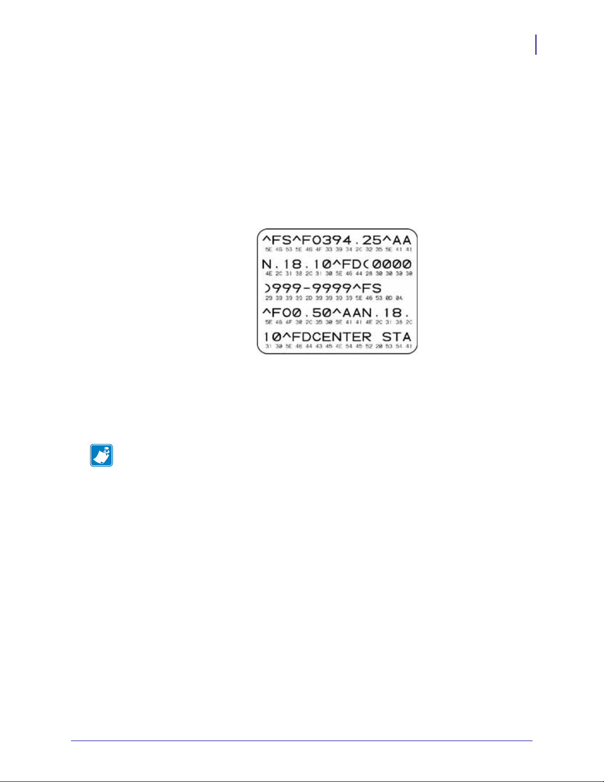
Communications Diagnostics Test
The communication diagnostics test is a troubleshooting tool for checking the interconnection
between the printer and the host computer.
When the printer is in diagnostics mode, it prints all data received from the host computer as
straight ASCII characters with the hex values below the ASCII text. The printer prints all
characters received, including control codes such as CR (carriage return). Figure 15 shows a
typical printout from this test. The actual format is modified to print on narrow wristbands.
Figure 15 • Communications Diagnostics Test Printout
Advanced User Information
Additional Diagnostics Tools
59
To use communications diagnostics mode, complete these steps:
1. Set the printer to Diagnostics mode by sending the ~JD ZPL II command to the printer.
The printer enters Diagnostics mode and prints any data received from the host computer
on a test printout
Note • The PAUSE/FEED button will not advance a wristband while the printer is in
Diagnostics mode. Exit Diagnostics mode to use that button and feed a wristband.
2. Check the test printout for error codes. For any errors, check that your communication
parameters are correct.
Errors show on the test printout as follows:
• FE indicates a framing error.
• OE indicates an overrun error.
• PE indicates a parity error.
• NE indicates noise.
3. Send the ~JE ZPL II command to the printer to return to normal operation.
7/17/12 HC100 User Guide 61207L-003
Page 74

Advanced User Information
60
Downloading Firmware
Downloading Firmware
Zebra periodically issues updated firmware to enhance the usability of its printers. You may
download the latest HC100 firmware to the printer at any time. For the latest firmware version
and instructions for downloading it, go to http://www.zebra.com/firmware.
Note • Zebra Technologies is aware that some safety and compliance organizations
require specific tested and approved firmware versions for the total system that uses the
wristband printer. Applying older firmware versions to newer printers may disable some
printer functions, such as networking.
Caution • During the firmware download process, the printer status indicator turns to a
steady half-orange and half-green as the printer writes to flash memory.
Do NOT power cycle the printer during this phase. Doing so makes the printer inoperable.
If necessary, contact technical support for assistance (see
Contacts on page vii).
You may choose to place the printer in forced download mode before downloading firmware.
While in this mode, the printer does not accept wristband printing instructions or control panel
button presses.
To place the printer in forced download mode, complete these steps:
1. Turn the printer off (O).
2. Press and hold PAUSE/FEED while turning on the printer (I).
During the printer self test, the printer status indicator rapidly alternates between yellow
and orange for 3 seconds.
3. Release PAU S E/FEED during this light sequence to enter forced download mode.
The printer status indicator alternates between green and orange lights.
4. Download firmware to the printer using any available connection.
As firmware is downloading, a green light rotates on the printer status indicator.
During the firmware download process, the printer status indicator turns to a steady halforange and half-green as the printer writes to flash memory. Do NOT power cycle the
printer during this phase.
When the firmware download process is complete, the printer returns to normal operation.
See Media Status Indicator on page 20 for more information on the indicator lights.
61207L-003 HC100 User Guide 7/17/12
Page 75

Specifications
This section contains the specifications for the printer and wristbands.
6
Contents
Physical and Environmental. . . . . . . . . . . . . . . . . . . . . . . . . . . . . . . . . . . . . . . . . . . . . . . 62
Printing. . . . . . . . . . . . . . . . . . . . . . . . . . . . . . . . . . . . . . . . . . . . . . . . . . . . . . . . . . . . . . . 62
Standard and Optional Features . . . . . . . . . . . . . . . . . . . . . . . . . . . . . . . . . . . . . . . . . . . 62
Power Cord . . . . . . . . . . . . . . . . . . . . . . . . . . . . . . . . . . . . . . . . . . . . . . . . . . . . . . . . . . . 63
7/17/12 HC100 User Guide 61207L-003
Page 76

Specifications
62
Physical and Environmental
Physical and Environmental
Physical
Dimensions (LxWxH) 9.5x5x7 in. (242x127x178 mm)
Clearance 6 in. (153 mm) above the printer to load a media cartridge
Weight 3.1 lb (1.4 kg)
Electrical 100-240 VAC, 50-60 Hz external power supply
Tem pe ra tu re
Operating 40° to 104°F (5° to 40°C)
Storage –40° to 140°F (–40° to 60°C)
Relative Humidity
Operating 20% to 85%, non-condensing
Storage 5% to 85%, non-condensing
Printing
Printhead Resolution 300 dpi
Print Speed 2 in./sec (51 mm/sec) or 4 in./sec. (102mm/sec.)
Note: Speed is set by the media cartridge.
Dot size (width x length) 0.0033 in. x 0.0039 in. (0.084 mm x 0.099 mm)
Minimum print length 3 in. (76 mm)
Maximum print length 22 in. (558 mm)
Bar code modulus
(X) dimension
3.27 mil to 32.67 mil
Standard and Optional Features
Memory • Standard 8 MB Flash (2 MB user available)
• Optional 64 MB Flash (58 MB user available)
• Standard 16 MB SDRAM (4 MB user available)
Connectivity • RS-232 Serial
•USB 2.0
• Optional 10/100 internal wired Ethernet (factory installed)
• Optional 802.11 b/g internal wireless Ethernet (factory installed)
Programming Languages •ZPL II
•XML
• Optional ZBI 2.0
61207L-003 HC100 User Guide 7/17/12
Page 77

Power Cord
3
1
2
4
Caution • For personnel and equipment safety, always use an approved three-conductor
power cord specific to the region or country intended for installation. This cord must use an
IEC 320 female connector and the appropriate region-specific, three-conductor grounded
plug configuration.
Depending on how your printer was ordered, a power cord may or may not be included. If one
is not included or if the one included is not suitable for your requirements, see Figure 16 and
refer to the following guidelines:
• The overall cord length must be less than 9.8 ft. (3 m).
• The cord must be rated for at least 10 A, 250 V.
• The chassis ground (earth) must be connected to ensure safety and reduce electromagnetic
interference.
Figure 16 • Power Cord Specifications
Specifications
Power Cord
63
AC power plug for your country—This should bear
1
the certification mark of at least one of the known
international safety organizations (Figure 17).
3-conductor HAR cable or other cable approved for
2
your country.
IEC 320 connector—This should bear the
3
certification mark of at least one of the known
international safety organizations (Figure 17).
Length ≤ 9.8 ft. (3 m). Rating 10 Amp, 250 VAC.
4
Figure 17 • International Safety Organization Certifications
7/17/12 HC100 User Guide 61207L-003
Page 78

Specifications
Notes • ___________________________________________________________________
__________________________________________________________________________
__________________________________________________________________________
__________________________________________________________________________
__________________________________________________________________________
__________________________________________________________________________
__________________________________________________________________________
__________________________________________________________________________
__________________________________________________________________________
__________________________________________________________________________
64
Power Cord
61207L-003 HC100 User Guide 7/17/12
 Loading...