


HC1
HEADSET COMPUTER
USER GUIDE


HC1 HEADSET COMPUTER
USER GUIDE
72E-165011-02
Rev. A
April 2015

ii HC1 Headset Computer User Guide
No part of this publication may be reproduced or used in any form, or by any electrical or mechanical means,
without permission in writing from Zebra. This includes electronic or mechanical means, such as photocopying,
recording, or information storage and retrieval systems. The material in this manual is subject to change
without notice.
The software is provided strictly on an “as is” basis. All software, including firmware, furnished to the user is on
a licensed basis. Zebra grants to the user a non-transferable and non-exclusive license to use each software
and firmware program delivered hereunder (licensed program). Except as noted below, such license may not
be assigned, sublicensed, or otherwise transferred by the user without prior written consent of Zebra. No right
to copy a licensed program in whole or in part is granted, except as permitted under copyright law. The user
shall not modify, merge, or incorporate any form or portion of a licensed program with other program material,
create a derivative work from a licensed program, or use a licensed program in a network without written
permission from Zebra. The user agrees to maintain Zebra’s copyright notice on the licensed programs
delivered hereunder, and to include the same on any authorized copies it makes, in whole or in part. The user
agrees not to decompile, disassemble, decode, or reverse engineer any licensed program delivered to the user
or any portion thereof.
Zebra reserves the right to make changes to any software or product to improve reliability, function, or design.
Zebra does not assume any product liability arising out of, or in connection with, the application or use of any
product, circuit, or application described herein.
No license is granted, either expressly or by implication, estoppel, or otherwise under any Zebra, intellectual
property rights. An implied license only exists for equipment, circuits, and subsystems contained in Zebra
products.

Revision History
Changes to the original guide are listed below:
Change Date Description
-01 Rev. A 07/10/13 Initial release.
-01 Rev. B 10/1/13 Minor updates.
-02 Rev. A 4/15 Zebra Rebranding
iii

iv HC1 Headset Computer User Guide

TABLE OF CONTENTS
Revision History .............................................................................................................................. iii
About This Guide
Introduction ..................................................................................................................................... ix
Documentation Set ................................................................................................................... ix
Configurations................................................................................................................................. ix
Software Versions..................................................................................................................... ix
Chapter Descriptions ...................................................................................................................... x
Notational Conventions................................................................................................................... x
Related Documents and Software .................................................................................................. xi
Service Information ......................................................................................................................... xi
Chapter 1: Getting Started
Introduction .................................................................................................................................... 1-1
Unpacking the Mobile Computer .................................................................................................... 1-1
Features ......................................................................................................................................... 1-2
HC1 Setup ..................................................................................................................................... 1-3
Installing the Battery ...................................................................................................................... 1-3
Charging the HC1 .......................................................................................................................... 1-4
Determining Dominant Eye ............................................................................................................ 1-7
Re-positioning the Computer/Optical Pod Assembly ..................................................................... 1-7
Re-positioning Speaker Module ..................................................................................................... 1-10
Placing the HC1 on Head .............................................................................................................. 1-10
Adjusting the Optical Boom ............................................................................................................ 1-13
Focus Display ................................................................................................................................ 1-16
Replacing the Battery ..................................................................................................................... 1-17
Replacing a Battery with Different Size .......................................................................................... 1-18
Chapter 2: Operation
Head Tracker Navigation ............................................................................................................... 2-1
Voice Control ................................................................................................................................. 2-2
Languages ............................................................................................................................... 2-3

vi HC1 Headset Computer User Guide
Mouse Navigation .......................................................................................................................... 2-3
Positioning Optical Pod When Not in Use ..................................................................................... 2-4
LED ................................................................................................................................................ 2-4
Suspend Mode ............................................................................................................................... 2-5
Resetting the HC1 ......................................................................................................................... 2-5
Desktop .......................................................................................................................................... 2-6
My Computer ................................................................................................................................. 2-7
Keyboards ................................................................................................................................ 2-9
Alpha-Numeric Keyboard ......................................................................................................... 2-9
Telephone Number Keyboard .................................................................................................. 2-10
IP Address Number Keyboard ................................................................................................. 2-10
Chapter 3: File Viewers
My Photos ...................................................................................................................................... 3-1
Zooming ............................................................................................................................. 3-3
Image Panning ................................................................................................................... 3-3
Freeze & Control Document Movement ............................................................................. 3-4
My Documents ............................................................................................................................... 3-4
Zooming ............................................................................................................................. 3-6
Paging ................................................................................................................................ 3-6
Image Panning ................................................................................................................... 3-6
Freeze & Control Document Movement ............................................................................. 3-7
My Videos ...................................................................................................................................... 3-7
Storage Card ................................................................................................................................. 3-9
Chapter 4: My Controls
Introduction .................................................................................................................................... 4-1
System Version .............................................................................................................................. 4-3
Changing the Device Name ..................................................................................................... 4-3
My Language ................................................................................................................................. 4-3
Head-Controlled Mouse ................................................................................................................. 4-4
Changing Mouse Speed .......................................................................................................... 4-4
Change Horizontal Movement ................................................................................................. 4-4
Change Vertical Movement ...................................................................................................... 4-5
Screen Brightness ......................................................................................................................... 4-5
Screen Rotation ............................................................................................................................. 4-5
Speaker Volume ............................................................................................................................ 4-6
Contrast Settings ........................................................................................................................... 4-6
Date and Time ............................................................................................................................... 4-7
Power Options ............................................................................................................................... 4-8
Setting Power Options ............................................................................................................. 4-9
Waking the HC1 ....................................................................................................................... 4-9
Launch Mode ................................................................................................................................. 4-9
Factory Settings ............................................................................................................................. 4-10
Chapter 5: My Network Controls
Introduction .................................................................................................................................... 5-1
Selecting a Network ....................................................................................................................... 5-2

Table of Contents vii
Configuring a Network ................................................................................................................... 5-4
Configuring Static IP Address ........................................................................................................ 5-4
Connecting to a Network ................................................................................................................ 5-6
Clearing the Preferred Network List ............................................................................................... 5-7
Chapter 6: My Bluetooth Controls
Introduction .................................................................................................................................... 6-1
Bluetooth SPP Devices ............................................................................................................ 6-2
Discovering Bluetooth Devices ...................................................................................................... 6-2
Pairing to a Bluetooth Device ......................................................................................................... 6-4
Connecting to a Bluetooth Device .................................................................................................. 6-5
Unpair a Bluetooth Device ............................................................................................................. 6-6
Removing a Bluetooth Device ........................................................................................................ 6-6
Chapter 7: My Telephone Controls
Introduction .................................................................................................................................... 7-1
Making a Call from the HC1 ........................................................................................................... 7-1
Answering a Call ...................................................................................................................... 7-2
Editing the Phone Book ........................................................................................................... 7-3
Chapter 8: Data Capture
Introduction .................................................................................................................................... 8-1
CS3070 Bluetooth Laser Scanner ................................................................................................. 8-1
Pairing with the HC1 ................................................................................................................ 8-1
Bar Code Capture with CS3070 Bluetooth Scanner ................................................................ 8-2
RS507 Hands-free Imager ............................................................................................................. 8-4
Pairing with the HC1 ................................................................................................................ 8-4
Bar Code Capture with RS507 Imager .................................................................................... 8-5
Chapter 9: Accessories
Introduction .................................................................................................................................... 9-1
Camera .......................................................................................................................................... 9-3
Installation ................................................................................................................................ 9-4
Removal ................................................................................................................................... 9-5
Installing a microSD Card ........................................................................................................ 9-5
microSD Card ................................................................................................................................ 9-7
Ear Buds ........................................................................................................................................ 9-8
Four Slot Battery Charger .............................................................................................................. 9-10
Battery Shim Installation .......................................................................................................... 9-10
Spare Battery Charging ........................................................................................................... 9-10
Battery Charging Indicators ..................................................................................................... 9-11
Charging Temperature ....................................................................................................... 9-11
Headstrap ...................................................................................................................................... 9-12
Neck Pad ....................................................................................................................................... 9-15

viii HC1 Headset Computer User Guide
Chapter 10: Maintenance & Troubleshooting
Introduction .................................................................................................................................... 10-1
Maintaining the HC1 ...................................................................................................................... 10-1
Battery Safety Guidelines .............................................................................................................. 10-1
Cleaning ......................................................................................................................................... 10-2
Approved Cleanser Active Ingredients ..................................................................................... 10-2
Harmful Ingredients .................................................................................................................. 10-2
Cleaning Instructions ............................................................................................................... 10-3
Special Cleaning Notes ............................................................................................................ 10-3
Materials Required ................................................................................................................... 10-3
Cleaning the HC1 ..................................................................................................................... 10-3
Housing .............................................................................................................................. 10-3
Display ............................................................................................................................... 10-3
Connector .......................................................................................................................... 10-3
Headstrap and Pads .......................................................................................................... 10-4
Cleaning Frequency ................................................................................................................. 10-4
Troubleshooting ............................................................................................................................. 10-5
HC1 .......................................................................................................................................... 10-5
Four-slot Spare Battery Charger .............................................................................................. 10-7
Appendix A: Specifications
HC1 and Accessory Technical Specifications ............................................................................... A-1
Glossary
Index

ABOUT THIS GUIDE
Introduction
This guide provides information about using the HC1 headset computers and accessories.
NOTE Screens and windows pictured in this guide are samples and may differ from actual screens.
Documentation Set
The documentation set for the HC1 is divided into guides that provide information for specific user needs.
•
HC1 Quick Reference Guide - describes how to start using the HC1 for the first time.
•
HC1 User Guide - describes how to use the HC1.
•
HC1 Integrator Guide - describes how to set up the HC1 and the accessories.
Configurations
This guide covers the following configurations:
Configuration Radios Display Memory
HC1 WLAN: 802.11 b/g
Software Versions
This guide covers various software configurations and references are made to operating system or software
versions. To determine the software versions:
WPAN: Bluetooth 2.1
with EDR
Color screen 512 MB RAM/
512 MB Flash
Data
Capture
optional
camera,
CS3070,
RS507
Operating
System
Windows CE 6.0
R3

x Headset Computer User Guide
Say “My Computer” > “My Controls” > “System Version.”
Chapter Descriptions
Topics covered in this guide are as follows:
•
Chapter 1, Getting Started, describes the HC1’s physical characteristics, how to install and charge the
batteries, remove and replace the handstrap and how to start the HC1 for the first time.
•
Chapter 2, Operation, provides basic instructions for using the HC1 and navigating the HC1 software.
•
Chapter 3, File Viewers, provides information for viewing photos, videos and documents.
•
Chapter 4, My Controls, describes how the HC1 works and affect its basic operation
•
Chapter 5, My Network Controls, provides information for connecting to a wireless network.
•
Chapter 6, My Bluetooth Controls, provides information for connecting to Bluetooth devices.
•
Chapter 7, My Telephone Controls, provides information for making and receiving phone calls using a
mobile phone or device.
•
Chapter 8, Data Capture, provides information about the optional data capture accessories.
•
Chapter 9, Accessories, describes the accessories available for the HC1 and how to use the accessories
to charge the HC1.
•
Chapter 10, Maintenance & Troubleshooting, includes instructions on cleaning and storing the HC1, and
provides troubleshooting solutions for potential problems during HC1 operation.
•
Appendix A, Specifications, includes a table listing the technical specifications for the HC1.
Notational Conventions
The following conventions are used in this document:
•
The term “headset computer” refers to the Zebra HC1.
•
Italics are used to highlight the following:
• Cha
• Dialo
• Dr
• Che
• Icons on a
pters and sections in this and related documents
g box, window and screen names
op-down list and list box names
ck box and radio button names
screen.

•
Bold text is used to highlight the following:
• Key names on a keypad
• Button names on a screen.
•
Bullets (•) indicate:
• Action items
• Lists of alternatives
• Lists of required steps that are not necessarily sequential.
•
Sequential lists (e.g., those that describe step-by-step procedures) appear as numbered lists.
Related Documents and Software
The following items provide more information about the HC1.
•
HC1 Quick Reference Guide, p/n 72-165008-xx
•
HC1 Integrator Guide, p/n 72E-165012-xx
About This Guide xi
For the latest version of this guide and all guides, go to: http://www.zebra.com/support
Service Information
If you have a problem with your equipment, contact Zebra Global Customer support for your region. Contact
information is available at:
When contacting Zebra Global Customer support, please have the following information available:
•
Serial number of the unit
•
Model number or product name
•
Software type and version number
Zebra responds to calls by email or telephone within the time limits set forth in support agreements.
If your problem cannot be solved by Zebra Global Customer Support, you may need to return your equipment
for servicing and will be given specific directions. Zebra is not responsible for any damages incurred during
shipment if the approved shipping container is not used. Shipping the units improperly can possibly void the
warranty.
If you purchased your product from a Zebra business partner, contact that business partner for support.
http://www.zebra.com/support.

xii Headset Computer User Guide

CHAPTER 1 GETTING STARTED
Introduction
This chapter describes the HC1 physical characteristics, how to install and charge the battery and how to
install the HC1 on your head.
Unpacking the Mobile Computer
Carefully remove all protective material from around the HC1 and save the shipping container for later storage
and shipping.
Verify that you received all equipment listed below:
•
HC1 headset computer
• Computer/Optical Pod Assembly
• Firm Goods Assembly
•
Lithium-ion battery
•
Speaker Module
•
Battery Cover
•
Quick Reference Guide.
Inspect the equipment for damage. If equipment is missing or damaged, contact the Zebra Global Customer
Support immediately. See
Service Information on page xi for contact information.
1 - 2 HC1 Headset Computer User Guide
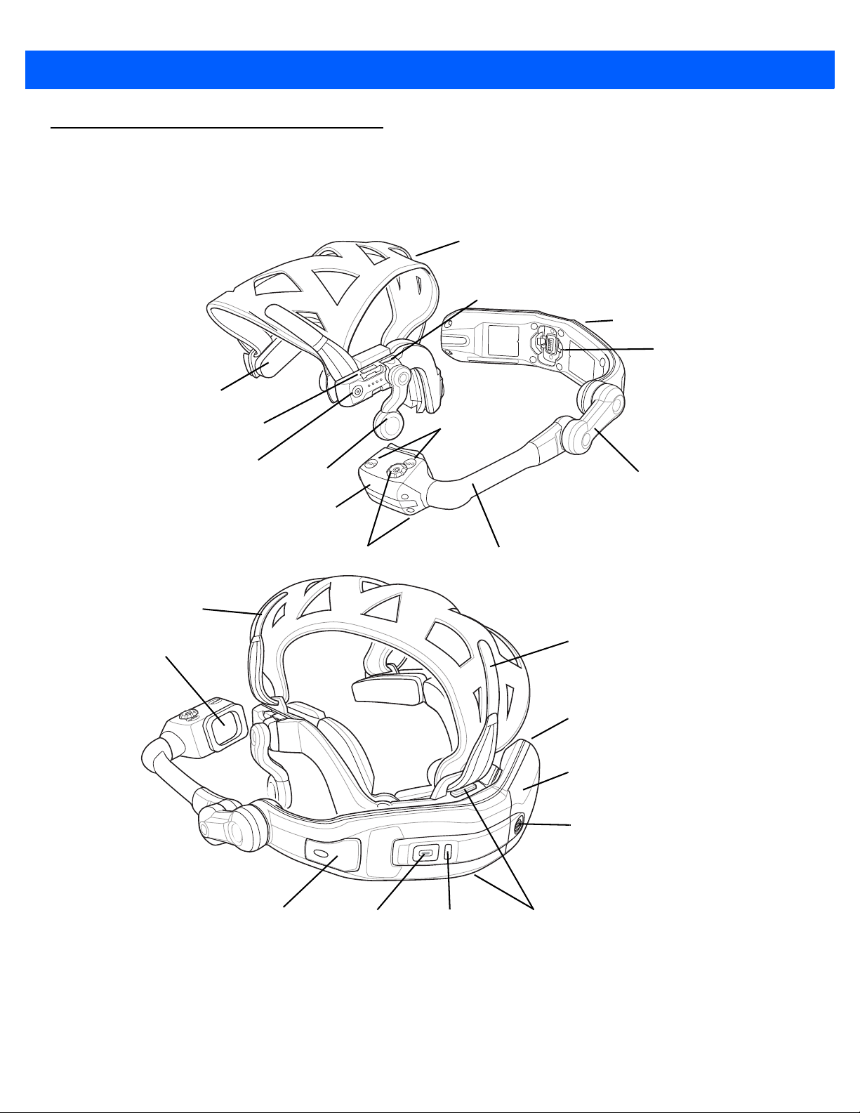
Optical Pod
Headstrap
Optical Boom
Programmable User
Button
(Default: Voice control on
or off)
Optical Focus
Computer/Optical Pod Assembly
Pivot Arm
Firm Goods Assembly
Speaker
Module
Computer
Neck Pad
Microphones
Power Connector/
Firm Goods Mount
Audio Port
Accessory Port
Battery Door
Door Screw
LEDPower Button
Release Latches
Display
SD Card
USB Port
Rear Adjustment tab
Left Adjustment
Ta b
Features
The features of the HC1 mobile computer are shown in Figure 1-1.
Figure 1-1
HC1 Headset Computer
HC1 Setup
Battery Release Latch
Contacts
Perform the following to setup the HC1:
•
Install the battery
•
Charge the HC1
•
Determining dominant eye
•
Re-position Computer/Optical Pod Assembly
•
Re-position speaker module
•
Place the HC1 on head
•
Adjust headset
•
Adjust optic pod.
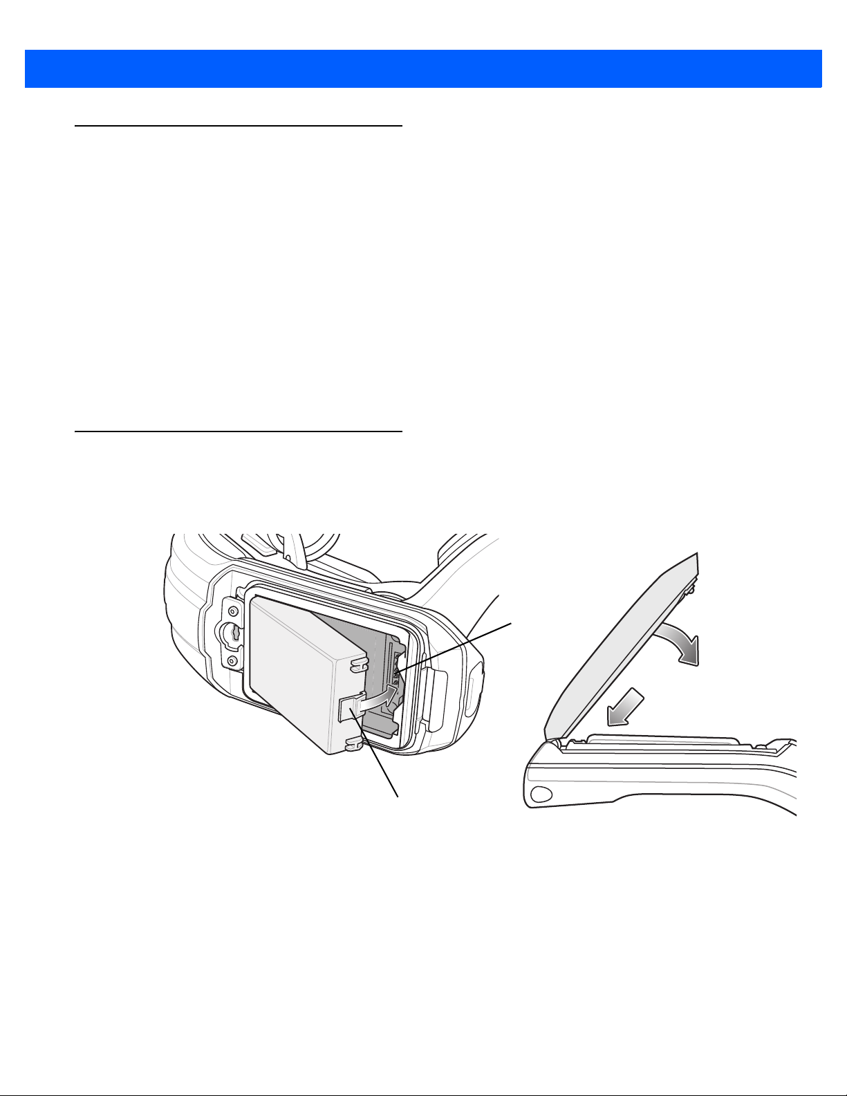
Installing the Battery
Getting Started 1 - 3
To install the battery:
1. Insert the battery into the battery well with the battery notches facing down and the release latch facing up.
Figure 1-2
2. Rotate the battery into the battery well until it snaps into place. If the battery is charged, the HC1 turns on.
3. Align the battery door with the housing.
Insert Battery
4. Close battery door.
1 - 4 HC1 Headset Computer User Guide
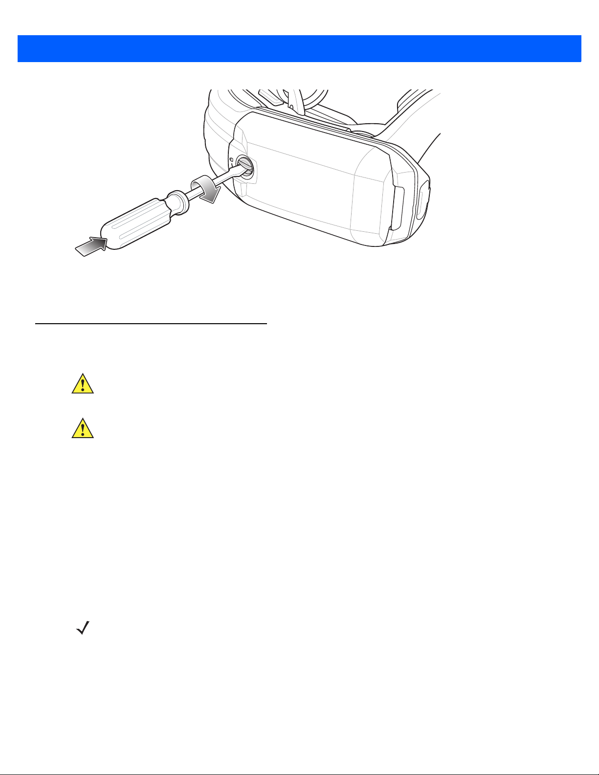
Figure 1-3
5. Using a screwdriver or coin, turn the locking screw clockwise 1/4 turn to the lock position.
Secure Battery Door
Charging the HC1
CAUTION Do not place on head while charging.
CAUTION Ensure that you follow the guidelines for battery safety described in Battery Safety Guidelines on page
The battery can be charged before insertion into the HC1 or after it is installed. Use the Four-slot Battery
Charger to charge the battery (out of the HC1) or the power module to charge the battery while it is installed in
the HC1.
Before using the HC1 for the first time, fully charge the
on page 1-7 for charge status indications). The 1950 mAh battery fully charges in less than four hours and the
4800 mAh battery fully charges in less than eight hours.
The HC1 is equipped with a backup battery which automatica
When using the HC1 for the first time, the backup battery requires approximately 30 hours to fully charge. This
is also true any time the backup battery is discharged, which occurs when the main battery is removed for
several hours. When the HC1 reaches a very low battery state, the combination of main battery and backup
battery retains clock data for at least 39 hours.
10-1.
battery until the LED Indicator remains lit (see Table 1-1
lly charges from the fully-charged main battery.
NOTE Batteries must be charged within the 0 ° to +40 ° C (32 ° to 104 ° F) ambient temperature range.
Press the release latches to remove the Firm Goods Assembly from the Computer/Optical Pod Assembly.
1.
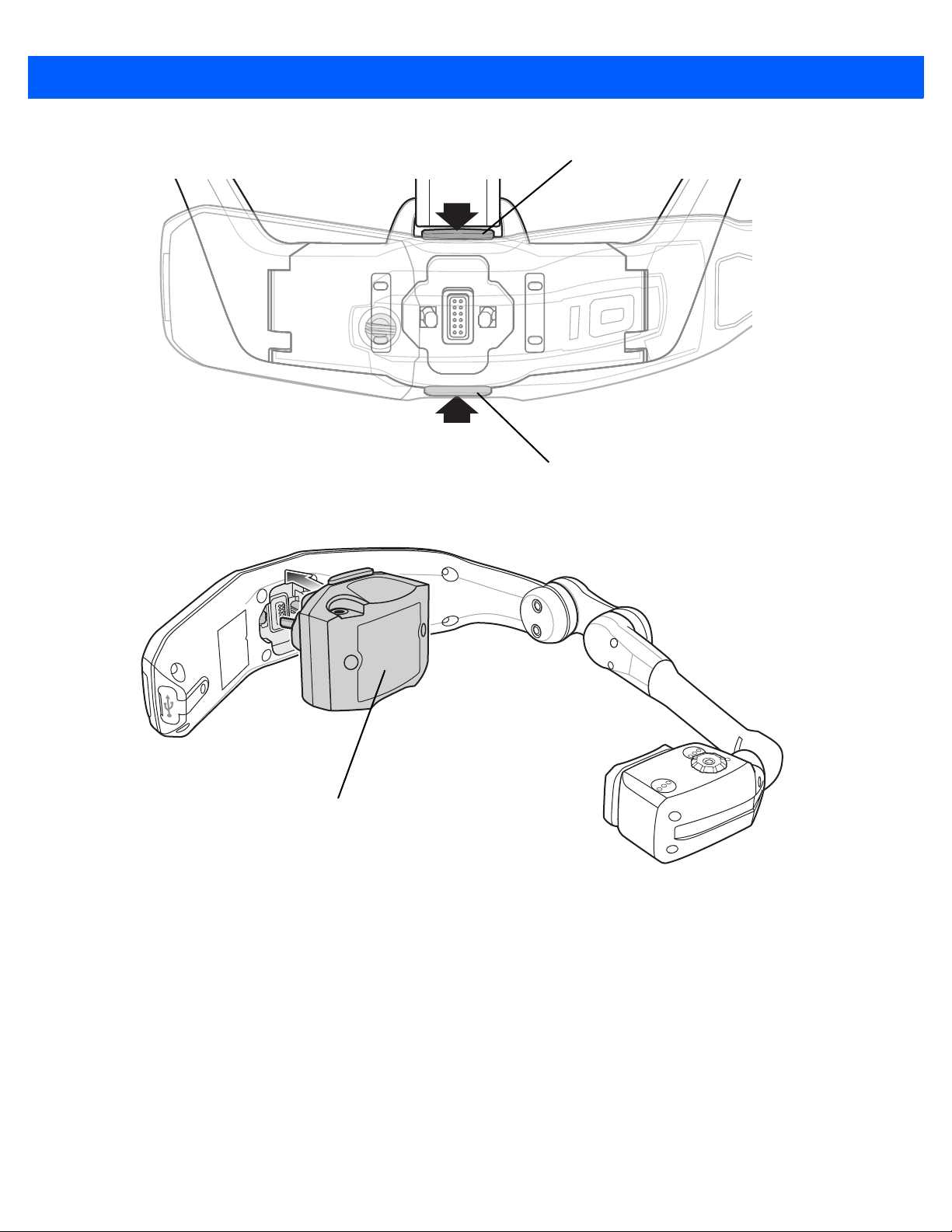
Bottom Release Latch
Top Release Latch
Getting Started 1 - 5
Charging Adapter
Figure 1-4
2. Connect the Charging Adapter to the Computer/Optical Pod Assembly.
Figure 1-5
3. Plug the Power Supply plug into the Charging Adapter and the Power Supply into a wall outlet.
Remove Firm Goods from Computer/Optical Pod Assembly
Connect Charging Adapter
or
Plug the Vehicle Charge Cable into the Charging
Adapter and into the vehicle power socket.
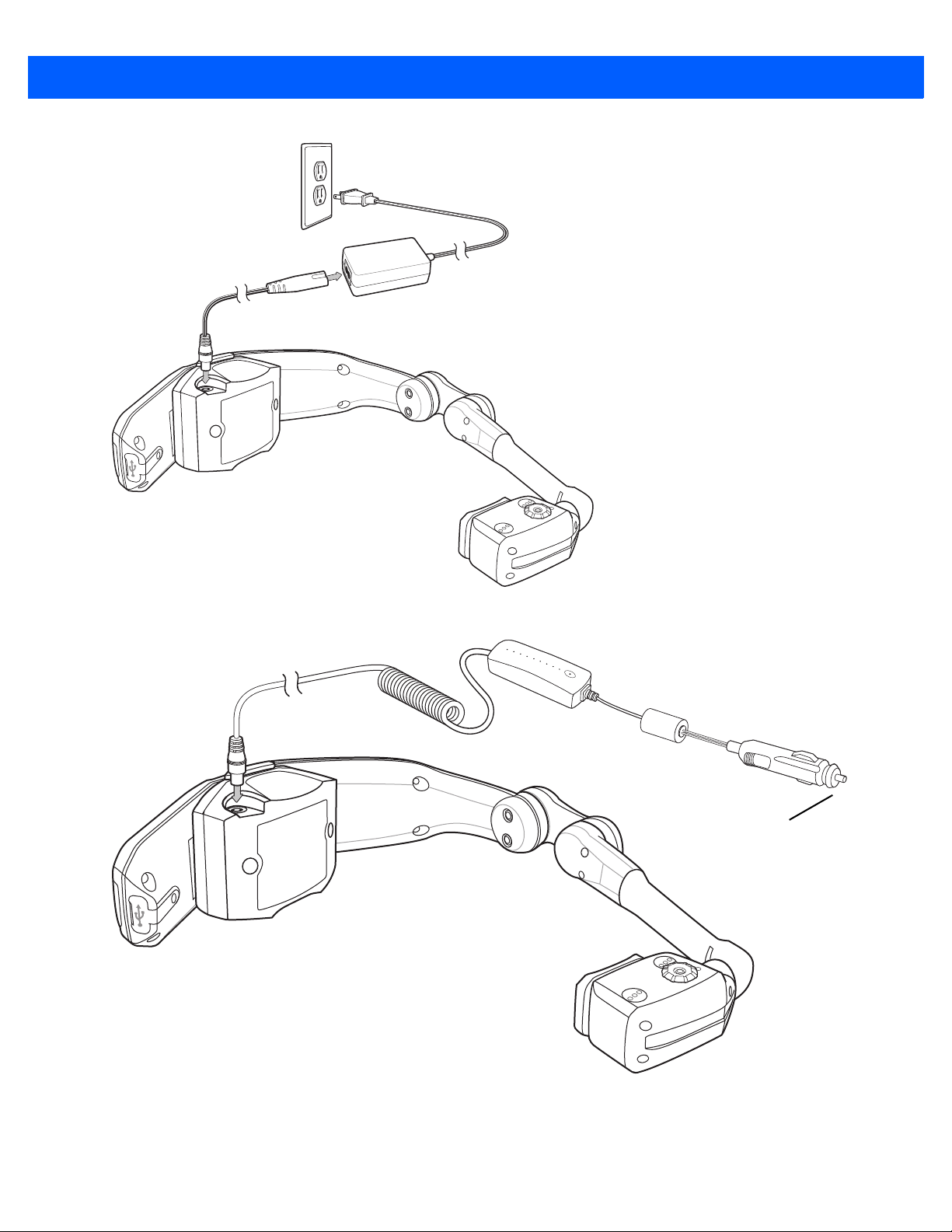
1 - 6 HC1 Headset Computer User Guide
To Vehicle
Power Socket
Figure 1-6
Connect AC Power Supply
Figure 1-7
4. Charge until the LED turns green.
Connect Vehicle Power Adapter
Getting Started 1 - 7
Table 1-1
Slow Flashing Amber HC1 is charging.
Solid Green HC1 is fully charged.
Fast Flashing Amber Charging error.
5. Press the Charging Adapter release latches and remove the Charging Adapter from the Computer/Optical
LED Indicator
LED State Description
Pod Assembly.
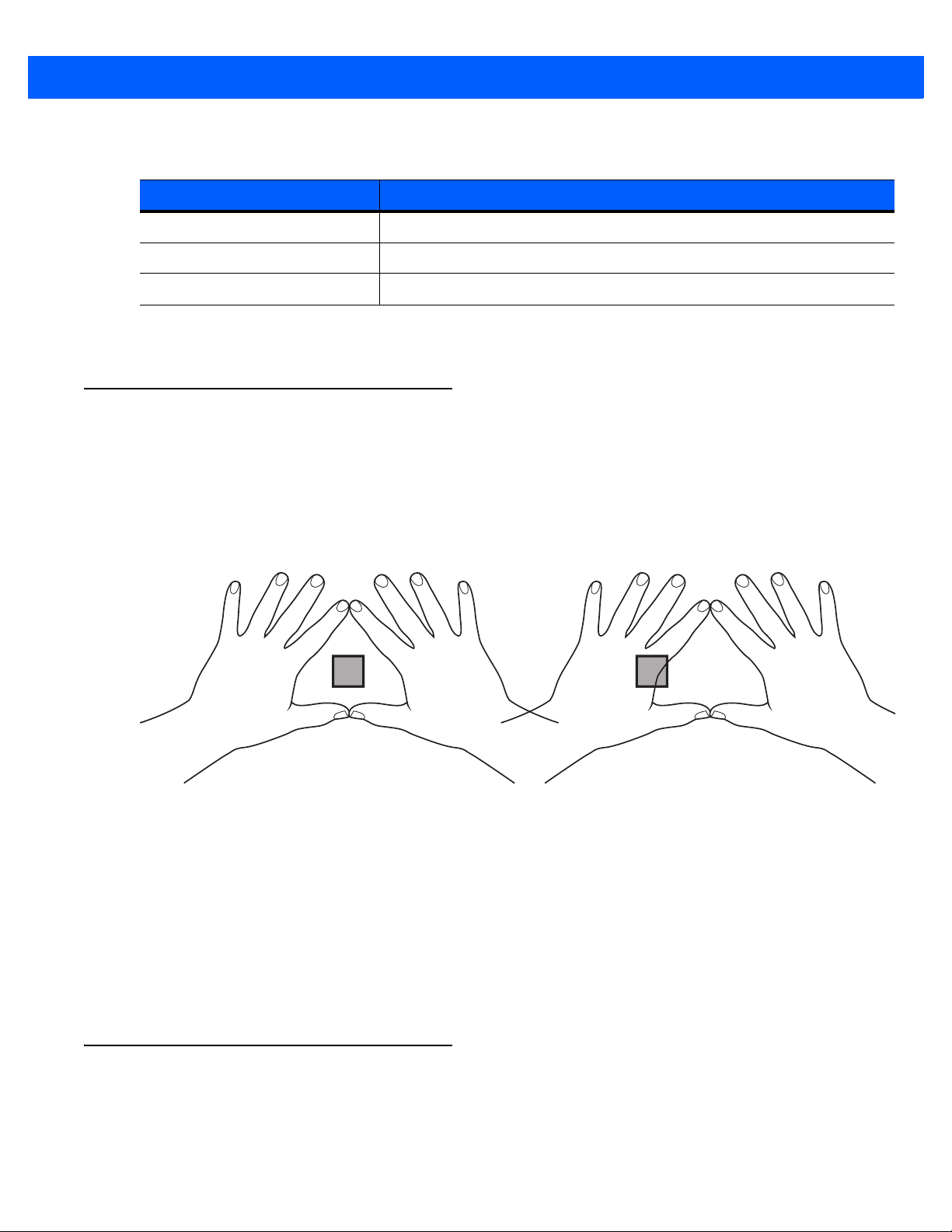
Determining Dominant Eye
Eye dominance is the tendency to prefer visual input from one eye to the other. Most people are right-eye
dominant; however in a small portion of the population neither eye is dominant. It is best to use your dominant
eye when viewing the display.
To determine which eye is dominant:
1. Place hands together as shown forming a triangle.
Figure 1-8
2. Keeping both eyes open, focus on any distant object.
3. Maintaining focus on the object centered in the triangle, close your right eye. If the object is still in the
triangle, you are left eye dominant.
4. Maintaining focus on the object centered in the triangle, close your left eye. If the object is still in the
triangle, you are right eye dominant.
5. If the object is in the triangle with either eye then you are dominant eye neutral.
6. Repeat test to confirm.
Dominant Eye Test
Re-positioning the Computer/Optical Pod Assembly
From the factory, the HC1 is configured for left eye dominant. To switch the optical pod position:
1. If not already removed, press the release latches to remove the Firm Goods Assembly from the
Computer/Optical Pod Assembly.
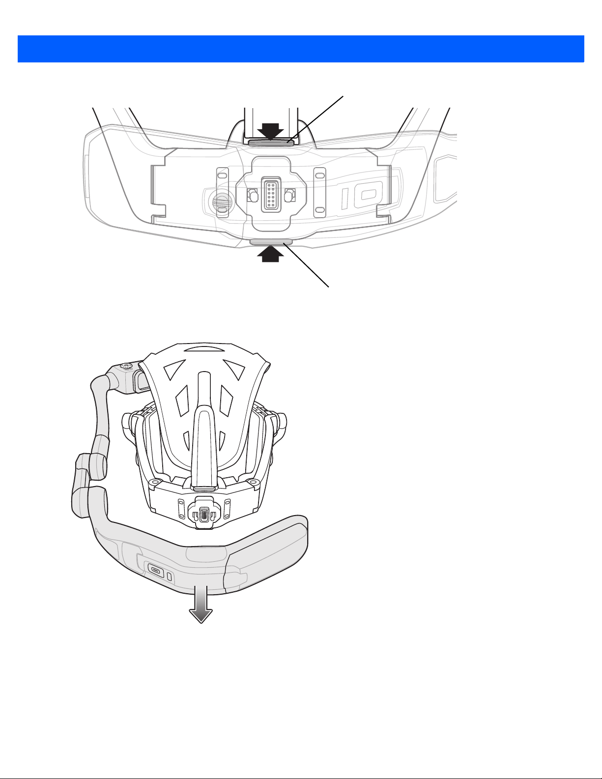
Bottom Release Latch
Top Release Latch
1 - 8 HC1 Headset Computer User Guide
Figure 1-9
2. Rotate the Computer/Optical Pod Assembly 180°.
Press Release Latches
Figure 1-10
Separate Firm Goods Assembly from Computer/Optical Pod Assembly
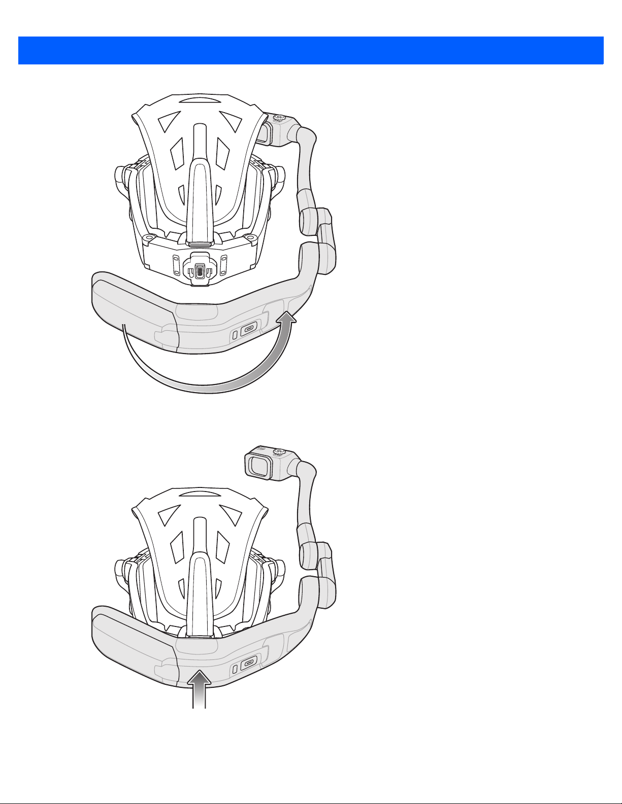
Getting Started 1 - 9
Figure 1-11
3. Reconnect the Firm Goods Assembly to the Computer/Optical Pod Assembly.
Flip Computer/Optical Pod Assembly
Figure 1-12
Re-Attach Computer/Optical Pod Assembly

1 - 10 HC1 Headset Computer User Guide
Speaker Release Latch
Contacts
Re-positioning Speaker Module
NOTE By default, the Speaker Module is installed on the right side. The user can switch the Speaker Module to
the left side if desired.
If switching the position of the Computer/Optical Po
re-position the Speaker Module.
4. Press release latch to remove Speaker Module from the Firm Good Assembly.
d Assembly was shifted it might be necessary to
Figure 1-13
5. Align the Speaker Module on the opposite arm. Ensure that the Speaker Module is connected to the
Re-Position Speaker Module
mating connector with the two contacts.
6. Press the Speaker Module in until it snaps into place.
Placing the HC1 on Head
The HC1 is worn on the head so that the main body of the device fits behind the base of the head with the strap
sitting on top of the head.
1. If the HC1 is off, press the power button to turn it on.
2. Grasp the HC1 by the Firm Goods Assembly arms.
3. Pull the arms out to expand Firm Goods Assembly arms.
4. Position the HC1 over head.

3
Getting Started 1 - 11
5
Figure 1-14
5. Place the HC1 onto the head. The front of the headstrap must be positioned at the top of the forehead.
Figure 1-15
6. Re-position the rear headstrap tab to position the height of the Computer/Optical Pod Assembly.
Expand HC1 Firm Goods Arms
Place HC1 on Head
7. Re-position the left and right headstrap tabs to position the arms above the ears.
Lengthen or shorten the head strap so that the ear loop
s are resting just above but not touching the ears.
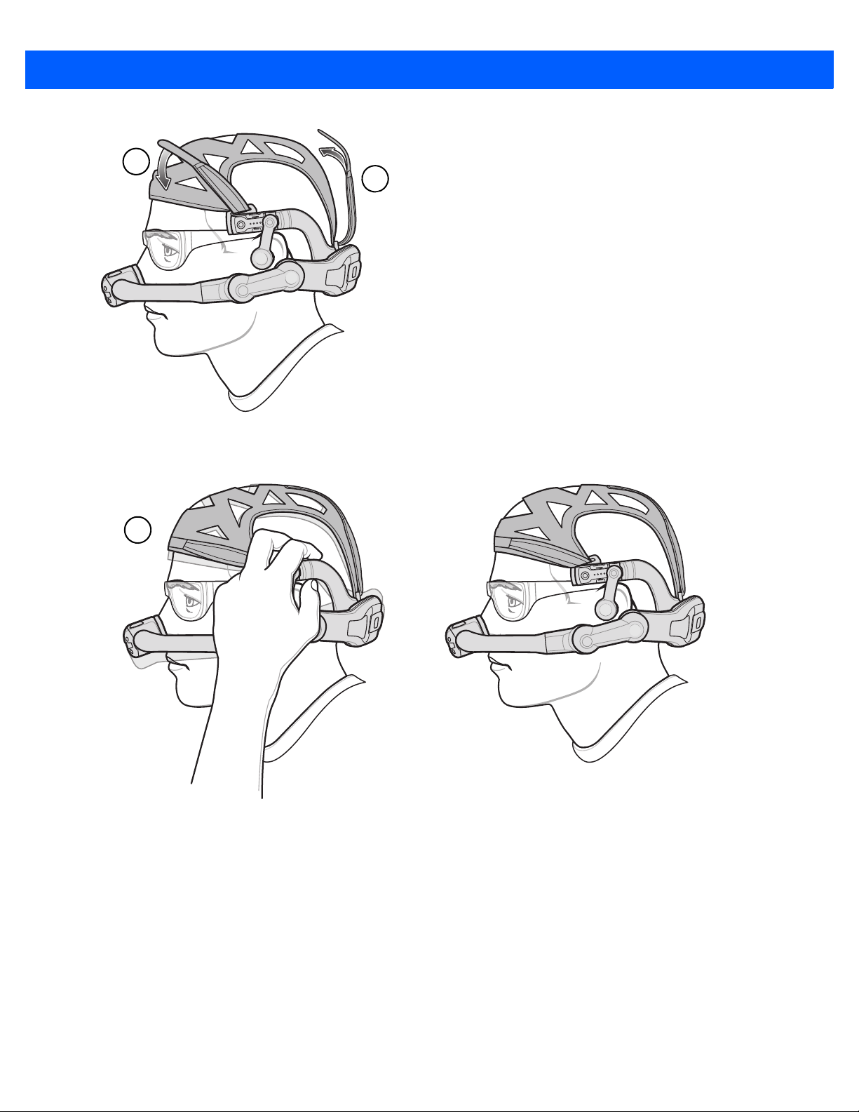
6
7
1 - 12 HC1 Headset Computer User Guide
8
Figure 1-16
8. Make sure the HC1 is balanced on head like you would a pair of eyeglasses.
Figure 1-17
Adjust Headstraps
Adjust HC1 on Head
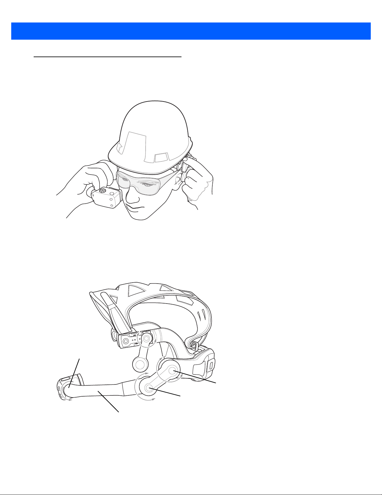
Adjusting the Optical Boom
Pod Pivot Point
Pod Pivot Point
Pod Pivot Point
Optical Boom
When adjusting the HC1 boom, hold the arm on the side opposite the boom when moving the boom up and
down.
Getting Started 1 - 13
Figure 1-18
The HC1 pivot points allow the user to properly position the Optica
user does not need to use it.
The Coarse Pivot Point allows for moving the Optical Pod la
tuning of the position. The Pod Pivot point allow for positioning of the display for viewing.
Adjusting the Optical Boom
l Pod and to move the optical Pod when the
rge distances. The Fine Pivot point allow for fine
Figure 1-19
Pivot Points
1 - 14 HC1 Headset Computer User Guide
Coarse Pivot Point
Fine Pivot Point
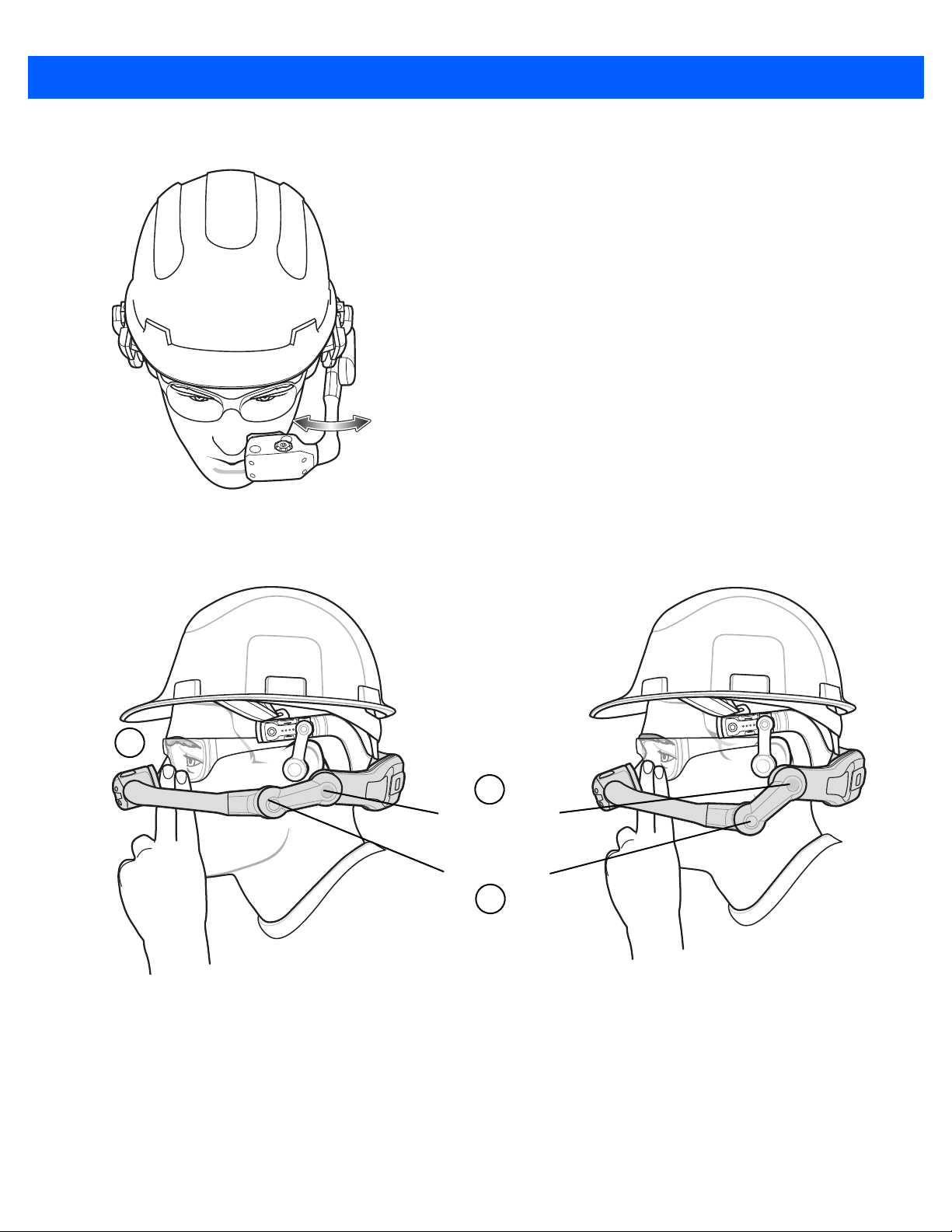
1
2
3
Move the Optical Boom in or out to position under eye.
Figure 1-20
Position the optical boom so that the Optical Pod is posit
wear.
Move Optical Boom
ioned approximately two fingers distance from the eye
Figure 1-21
The Optical Pod must be positioned so that it do
Optical Pod Alignment
es not block the line of sight of the user.
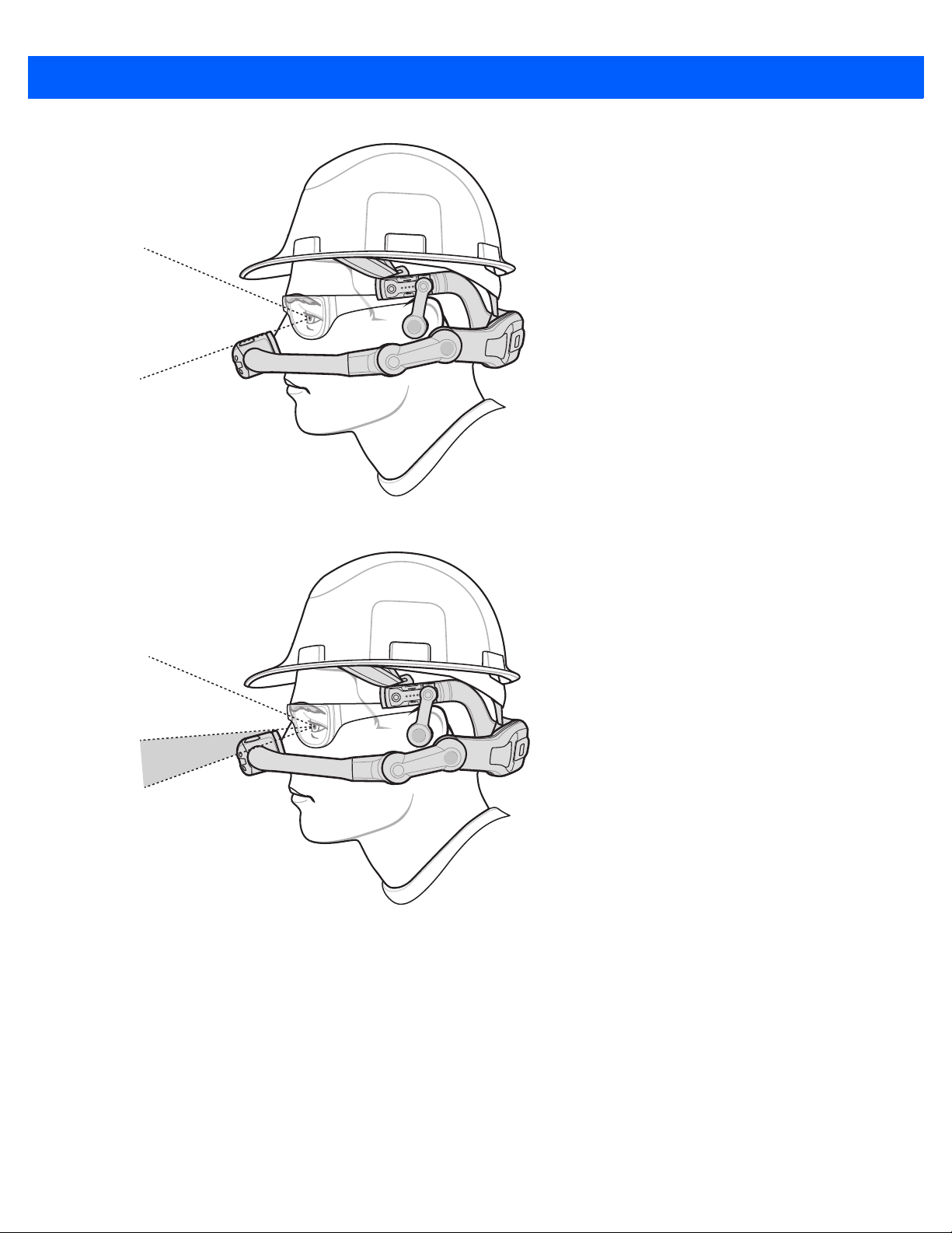
Getting Started 1 - 15
Figure 1-22
Figure 1-23
1. Hold the HC1 with one hand and rotate the arm at the Coarse Pivot Point.
Proper Position of Optical Pod
Blocked Field of View
2. Hold the HC1 with one hand and rotate the arm at the Fine Pivot Point.
3. Repeat adjustments until the Optical Pod is two finger lengths away from safety glasses and out of the
user’s line of sight.
4. Adjust the optical boom to position the display left or right.
5. Rotate the Optical Pod for best viewing angle.

5
1 - 16 HC1 Headset Computer User Guide
Figure 1-24
Adjust Optical Pod
Focus Display
To focus the display:
1. Look into the display.
2. There are two display dials for controlling the focus. One on top and one on the bottom. With thumb and
index finger, squeeze dials.
3. Rotate the display dials either clockwise or counter-clockwise until the display appears in focus.
Figure 1-25
If the Computer/Optical Pod Assembly was ro
“My Controls” > “Screen Rotation” > “Rotate Screen.”
Focus Display
tated, the display appears upside down. Say “My Computer” >

Replacing the Battery
CAUTION Prior to replacing the battery, save all data to persistent storage or the microSD card and close all
running applications. Failure to do so will result in loss of data.
To replace the same battery size:
1. Press the Power button for one second to place the HC1 in suspend mode. The display turns off and the
LED light red.
2. Wait for the LED to turn off.
3. Using a screwdriver or coin, turn the locking screws counterclockwise 1/4 turn to the unlock position.
Getting Started 1 - 17
Figure 1-26
4. Lift battery door.
5. Remove the battery from the HC1.
6. Insert the replacement battery into the battery well with the battery notches facing down and the release
Unlock Battery Door
latch facing up.

Battery Release Latch
Contacts
1 - 18 HC1 Headset Computer User Guide
Figure 1-27
7. Rotate the battery into the battery well until it snaps into place.
8. Align the battery door with the housing.
9. Close battery door.
Figure 1-28
10. Using a screwdriver or coin, turn the locking screes clockwise 1/4 turn to the lock position. The HC1 turns
Insert Battery
Secure Battery Door
on.
Replacing a Battery with Different Size
CAUTION Prior to replacing the battery, save all data to persistent storage or the microSD card and close all
running applications. Failure to do so will result in loss of data.
To replace a 1950 mAh battery with a 4800 mAh battery or a 4800 mAh battery with a 1950 mAh battery:

Getting Started 1 - 19
Battery Release Latch
Contacts
1. Press the Power button for one second to place the HC1 in suspend mode. The display turns off and the
LED light red.
2. Wait for the LED to turn off.
3. Using a screwdriver or coin, turn the locking screws counterclockwise 1/4 turn to the unlock position.
Figure 1-29
4. Lift battery door.
5. Remove the battery from the HC1.
6. Insert the replacement battery into the battery well with the battery notches facing down and the release
Unlock Battery Door
latch facing up.
Figure 1-30
7. Rotate the replacement battery into the battery well until it snaps into place.
8. Align the appropriate battery door with the housing.
9. Close battery door.
Insert Battery

1 - 20 HC1 Headset Computer User Guide
Figure 1-31
10. Using a screwdriver or coin, turn the locking screes clockwise 1/4 turn to the lock position.
11. The HC1 boots. A message appears on the display indicating that the user must connect the HC1 to
Secure Battery Door
external power or perform a reboot.
12. Perform a cold boot (see Resetting the HC1 on page 2-5) or connect the HC1 to external power for
approximately eight seconds.

CHAPTER 2 OPERATION
Latch
Equipment Plug
Master Socket
Leased
Line
Leased
Line
6 - 0
5 - R
4 - B
3 - G
2 - W
470k
1.6vF
1 - BK
A-Wire
B-Wire
Local
Earth
Latch
ell
eech
pression
Latch
Equipment Plug
6 - 0
5 - R
4 - B
3 - G
2 - W
1 - BK
Bell
Speech
Suppression
Dial
Off
Normal
Signal
Circuits
This chapter provides basic operation information for the HC1 headset computer.
Head Tracker Navigation
The HC1 contains 9-axis head tracking sensors that allow the user to move the objects on the display by
moving their head up and down and left and right.
Figure 2-1
Scrolling Left and Right

2 - 2 HC1 Headset Computer User Guide
Latch
Equipment Plug
Master Socket
Leased
Line
Leased
Line
6 - 0
5 - R
4 - B
3 - G
2 - W
470k
1.6vF
1 - BK
A-Wire
B-Wire
Local
Earth
Latch
Bell
Speech
ppression
se
ed
B
B
Latch
Equipment Plug
Master Socket
Leased
Line
Leased
Line
6 - 0
5 - R
4 - B
3 - G
2 - W
470k
1.6vF
1 - BK
A-Wire
B-Wire
Local
Earth
Latch
Bell
B
Meus Controles
Fechar Janela
“Fechar Janela”
Programmable Button
As the user moves head left or right, the image on the display scrolls accordingly. Moving the head up and
down moves the image on the display accordingly.
Figure 2-2
Voice Control
The HC1 is equipped with voice recognition software that allows the user to control software functionality by
speaking on-screen commands.
Figure 2-3
Each Firm Goods arm contains a programmable user butto
either of the buttons, voice controls are turned off. A dialog box appears on the screen notifying the user.
Scrolling Up and Down
Voice Commands
n. By default, when the user presses and releases

Zebra recommends that the user turn off voice controls to eliminate any inadvertent commands due to noisy
environments or communication with another person. Press and release the button to turn on voice control.
Speech Recognizer commands can only be directed at the currently focused foreground window.
Languages
The HC1 supports the following languages:
•
English
•
French
•
German
•
Italian
•
Spanish.
See My Language on page 4-3 for information about setting a different language.
Mouse Navigation
Operation 2 - 3
For applications that are not voice control enabled (such as the desktop), the user can control the mouse
cursor movement on the screen by moving their head left and right and up and down. The cursor moves across
the screen according to the Head-controlled mouse settings. See
more information.
To simulate pressing the left button once, say “Mouse Click.” To simulate pressing the left button twice say
“Mouse Double-click.” To simulate pressing the right button once, say “Mouse Right Click.”
Head-Controlled Mouse on page 4-4 for

2 - 4 HC1 Headset Computer User Guide
Positioning Optical Pod When Not in Use
The user can move the Optical Pod away from the face when it is not being used for long periods of time.
Grasps the boom and rotate up and away from the face.
LED
Figure 2-4
The LED on the HC1 indicates the following:
Table 2-1
Charging
Slow Flashing Amber HC1 is charging.
Solid Green HC1 is fully charged.
Fast Flashing Amber Charging error.
Raise Optical Pod
LED Indicator
LED State Description

Operation 2 - 5
Table 2-1
Boot Up
Fast Flashing Red During boot up on battery power, battery door or SD card cover are open.
Slow Flashing Red During booting up operating system update. User must attach power to the
LED Indicator
Suspend Mode
In suspend mode the HC1 powers down to save battery power. The HC1 can be placed in suspend mode
manually or it can go into suspend mode automatically.
To place the HC1 in suspend mode press and hold the Power button for one second. The LED lights red and
then display
After a period of inactivity, the HC1 first goes into idle mode (screen darkens) and then goes into Suspend
de.
mo
To wake the HC1 from suspend mode press the Power button. After about six seconds the display turns on.
turns off.
LED State Description
HC1 to
update image.
Resetting the HC1
CAUTION All unsaved data is lost when performing a cold boot.
If the HC1 stops responding perform a cold boot. Press the Power button for eight seconds. Initially the HC1
requires approximately 30 seconds to boot-up, during which time the booting screen displays.
After boot up, the desktop or applications window displays.

2 - 6 HC1 Headset Computer User Guide
G-i Services Icon
Desktop
The HC1 is a Windows CE 6.0 computer with a number of HC1 specific features. These features include: the
speech recognizer, the Head-Tracker, the Bluetooth and the Wi-Fi subsystems.
Together these features allow applications to be design
typically hands-free and voice driven.
ed and implemented for the HC1, applications that are
Figure 2-5
The desktop is not the ideal starting place for end users. T
as the HC1 is deployed it will be configured to completely hide the desktop in favor of a more speech driven
solution.
The WinCE desktop is standard but has a built in speech r
applications that are designed to be used in hands-free mode.
The green microphone in the task tray indicates that the spe
pop-up menu associated with it, allowing key components of the services to be accessed as an alternative to
issuing similar spoken commands.
Figure 2-6
HC1 Desktop
he HC1 is highly configurable at is it expected that
ecognizer and a built in set of commands and
ech-enabled services are running. This icon has a
G-i Services Icon

My Computer
NOTE When the My Computer window is in focus, the head-tracking mouse cursor is disabled.
Use the My Computer window as a launch pad for operating the HC1. Say “My Computer” to launch the My
Computer screen.
Operation 2 - 7
Figure 2-7
The main screen has the following options:
•
•
•
•
•
•
My Computer Window
NOTE The My Computer window shows the default configuration and may vary depending upon applications
installed on the HC1.
My Photos - view photos on the HC1. See My Photos on page 3-1 for more information.
My Videos - view videos on the HC1. See My Videos on page 3-7 for more information.
My Documents - view documents on the HC1. See My Documents on page 3-4 for more information.
Storage Card - view files on the optional microSD card installed in the HC1. See Storage Card on page
3-9 for more information.
My Controls - use to control settings of the HC1. See Chapter 4, My Controls for more information.
My Network Controls - use to setup wireless network. See Chapter 5, My Network Controls for more
information.

2 - 8 HC1 Headset Computer User Guide
•
My Bluetooth Controls - use to configure Bluetooth and connect Bluetooth devices to the HC1. See
Chapter 6, My Bluetooth Controls for more information.
•
My Telephone Controls - use to make and answer phone calls when connected to a phone. See
Chapter 7, My Telephone Controls for more information.
The status bar at the top of the window lists various icons depending upon configuration. Table 2-2 lists the
various icons that may appea
r in the status bar.
Table 2-2
Status Icons
Icon Name Description
Battery Very Low Indicates the battery charge level is less than 15%.
Battery Low Indicates the battery charge level is greater than 15%.
Battery Good Indicates the battery charge level is greater than 30%.
Battery Very Good Indicates the battery charge level is greater than 60%.
Battery Fully Charged Indicates the battery charge level Greater than 80%.
Wi-Fi Off The Wi-Fi radio is off.
Wi-Fi On Not
Connected
Wi-Fi Connected The Wi-Fi radio is on and connected to a network. Each bar
Bluetooth On The Bluetooth radio is on.
The Wi-Fi radio is on but not connected to a network.
indicates the signal strength of the connection.
Telephone Connected The HC1 is connected to a mobile device.
Telephone Call In
Progress
The HC1 is connected to a mobile device and a phone call
is in process.

Operation 2 - 9
Keyboards
NOTE Keyboard access is application dependent.
Throughout the use and configuration of the HC1, there are times when text or numbers are required. In these
events, menus of pre-configured options are not applicable. To allow for this the HC1 can display a number of
virtual keyboards that allow text or numbers to be entered.
NOTE All virtual keyboards allow direct typed input from a real keyboard. For example, a Bluetooth keyboard can
be connected and used, a USB keyboard can be connect and used and remote control software allows a
computer keyboard to be used with the HC1.
Alpha-Numeric Keyboard
The Alpha-Numeric keyboard allows any text or number combination to be entered via voice. To enter single
text characters, the radio-alphabet code must be spoken, for example “alpha.” The radio code to speak is
shown beneath each virtual key.
Numbers are entered by speaking the number, for example “one.”
To increase speed and accuracy, digits, lowercase letters an
three, for example “alpha-delta-tango” or “one-two-three.”
To delete the previous spoken command, say “Clear.”
The user can also enter number and letters by using the
keyboard. Say “Mouse Click” to select a key on the keyboard.
head-tracking to move the arrow cursor around the
d uppercase letters can be spoken in groups of
Figure 2-8
Alpha-numeric Virtual Keyboard

2 - 10 HC1 Headset Computer User Guide
Telephone Number Keyboard
The Telephone Number keyboard allows any number combination to be entered via voice. To enter single
numbers simply say the numbers one at a time.
To increase speed and accuracy, numbers can be spoken in g
“seven.”
To delete the previous spoken command, say “Undo.”
Figure 2-9
Telephone Number Virtual Keyboard
roups of three, for example “one,” “three,”
IP Address Number Keyboard
The IP Address keyboard allows any number combination to be entered via voice. To enter single numbers
simply say the numbers one at a time.
To increase speed and accuracy, numbers can be spoken in g
“seven.”
To delete the previous spoken command, say “Undo.”
IP Address Virtual Keyboard
roups of three, for example “one,” “three,”

CHAPTER 3 FILE VIEWERS
File viewers allows the user to view photos, videos and documents loaded on the HC1.
My Photos
Use My Photos to view photos that are loaded on the HC1. The HC1 supports the following formats:
•
JPEG
•
PNG
•
GIF
•
BMP.
To view photos:
1. Say “My Computer.”
2. Say “My Photos.” The Photos window appears.

3 - 2 Headset Computer User Guide
Figure 3-1
Each icon in the window represents a photo on the HC1 in
prefixed by Select. Under the filename is Select File x, where x is the number of the file.
To open the file say the filename or the
The photo opens in the photo viewer.
Photos Window
ternal memory. Under the icon is the filename
file number. For example: say “Select Building 1” or say “Select File 3.”

File Viewers 3 - 3
Figure 3-2
Photo Viewer Window
Zooming
The Photo Viewer supports three levels of zoom. To enlarge the photos say “Zoom Level 2” or “Zoom Level 3.”
Image Panning
The Photo Viewer allows the use to view parts of the photo that are off the screen. Move head left and right or
up and down. The thumbnail of the photos indicates the position of the display in reference to the photo.

3 - 4 Headset Computer User Guide
Figure 3-3
Panning in Photo Viewer
Freeze & Control Document Movement
If the user wants to keep the photo still while doing other work and ensure that the photo is in the same place,
say “Freeze Document.” The display locks in position so that head movement does not move the photos. To
return to normal viewing say “Control Document.”
My Documents
Use My Documents to view documents that are loaded on the HC1. The HC1 supports Microsoft® Office 2007
and newer file formats, text and pdf files.
To view a document:
1. Say “My Computer.”
2. Say “My Documents.” The Documents window appears.

File Viewers 3 - 5
Figure 3-4
Each icon in the window represents a document on the HC1
prefixed by Select. Under the filename is Select File x, where x is the number of the file.
To open the file say the filename or the file number. For
File 2.”
The document opens in a viewer depending upon the type of document.
Documents Window
internal memory. Under the icon is the filename
example: say “Select Circuit Locations” or say “Select

3 - 6 Headset Computer User Guide
Figure 3-5
Document Viewer Window
Zooming
The Document Viewer supports three levels of zoom. To enlarge the photos say “Zoom Level 2” or “Zoom
Level 3.”
Paging
The Document Viewer supports viewing multiple pages. To go to a specific page say “View Page x” Where x is
the page number. To go to the next or previous page say “Next Page” or “Previous Page.”
Image Panning
The Document Viewer allows the use to view parts of the document that are off the screen. Move head left and
right or up and down. The thumbnail of the document indicates the position of the display in reference to the
document.

File Viewers 3 - 7
Figure 3-6
Freeze & Control Document Movement
If the user wants to keep the photo still while doing other work and ensure that the photo is in the same place,
say “Freeze Document.” The display locks in position so that head movement does not move the photos. To
return to normal viewing say “Control Document.”
To set the document back to the original position and size say “Reset Document.”
My Videos
Use My Videos to view video files that are loaded on the HC1 internal memory. The HC1 supports the
following video formats:
•
•
•
To view videos:
1. Say “My Computer.”
2. Say “My Videos.” The Videos window appears.
Panning in Document Viewer
WMV9 (AVI)
MPEG-4
H.264

3 - 8 Headset Computer User Guide
Figure 3-7
Each icon in the window represents a video on the HC1 internal memory. Under the icon is the filename
refixed by “Select.” Under the filename is Select File x, where x is the number of the file.
p
To open the video say the filename or the file number. For exam
1.”
The video opens in the movie viewer.
Videos Window
ple: say “Select Iron Man” or say “Select File

File Viewers 3 - 9
Figure 3-8
The video automatically plays when the viewer opens.
•
Say “Video Pause” to stop the video.
•
Say “Video Resume” to continue to play the video.
•
Say “Video Stop” to stop playing the video. The viewer closes and the Videos window appears.
Storage Card
Use Storage Card to view files that are loaded on the optional microSD card. Files on the microSD card can
be photos, documents or videos.
To view files on the microSD card:
1. Say “My Computer.”
2. Say “Storage Card.” The Storage Card window appears.
Movie Viewer

3 - 10 Headset Computer User Guide
Figure 3-9
Each icon in the window represents a file on the micro
Select. Under the filename is Select File x, where x is the number of the file.
To open the file say the filename or the file number. For
Depending upon the file type, the corresponding viewer displays. See My Photos on page 3-1 for information
on the photo viewer, My Videos on page 3-7 for information on the movie viewer or My Documents on page 3-4
for information on the document viewer.
Storage Card Window
SD card. Under the icon is the filename prefixed by
example: say “Select Wildlife” or say “Select File 4.”

CHAPTER 4 MY CONTROLS
Introduction
Use My Controls to control how the HC1 works and affect its basic operation. All of the My Control modules
are accessed from any screen by saying “My Computer” > “My Controls”.
Figure 4-1
The My Cont
head movement to scrolling the window left or right. To select a particular module within the My Controls
window say the name of the module. The module does not need to be visible in the window in order to issue
the command.
To close the My
Table 4-1 list the modules available in the My Cont
My Controls Window
rols window displays a number of icons. The icons extends past the sides of the window. Use
Controls window at any time, say “Window Close.”
rols window:

4 - 2 Headset Computer User Guide
Table 4-1
My Controls Modules
Icon Name Description
System Version Display the current system version numbers, including the base
operating system version and the SDK versions.
My Language Switch to a different language.
Head-Controlled Mouse Controls mouse functionality when navigating non-voice enabled
applications.
Screen Brightness Vary the brightness of the screen.
Screen Rotation Rotate the screen display 180 degrees to support left eye or right
eye configuration.
Speaker Volume Control the speaker volume.
Contrast Settings Control the screen contrast.
Date and Time Set the date and time.
Power Options Set power saving options.
Launch Mode Set how the HC1 is configured upon boot up. Set to open with
either the desktop or the My Computer window.
Factory Settings Reset the HC1 to factory My Controls default values.

System Version
Use the System Version module to display the current system version numbers, including the base operating
system version and the SDK versions.
My Controls 4 - 3
Figure 4-2
The System V
via Bluetooth or Wi-Fi. The default device name is HC1.
System Version
ersion module also allows the user to set the name of the HC1. This name is visible to devices
Changing the Device Name
To change the name:
1. Say “Change Name.” The virtual keyboard displays.
2. Use the virtual keyboard to enter the device name. See Keyboards on page 2-9 for information on using
the virtual keyboards.
3. Say “Window OK.” The System Version window displays with the new name.
4. Say “Window Close” or “Navigate Back.”
My Language
Use the My Language module to switch to a different language. The available languages are shown in the
window and are selected by saying the language name.
Once a new language has been selected, the on-screen labels
speech recognizer.
switch to the new language, as well as the
•
English
•
French
•
German
•
Italian
•
Spanish.
To change the language:
1. Say “My Controls.”
2. Say “My Languages.”

4 - 4 Headset Computer User Guide
Figure 4-3
3. Say the name of the language. The system language changes to the selected language.
4. In the new language, say “Window Close” or “Navigate Back.”
My Language Window
Head-Controlled Mouse
Use the Head-Controlled Mouse module to control the mouse movement on the screen.
Figure 4-4
Changing Mouse Speed
Head-Controlled Mouse Window
To change the speed of mouse movement:
1. Say “My Controls.”
2. Say “Head-Controlled Mouse.” The Head-Controlled Mouse window appears.
3. Say “Level x” where x represents the level number with 1 being the slowest and 5 being the fastest.
Change Horizontal Movement
By default, when the user moves head to the left, the mouse cursor on the screen moves to the right. To
change the horizontal mouse movement so that when moving head to the left the mouse (cursor) moves to the
left:
1. Say “My Controls.”
2. Say “Head-Controlled Mouse.” The Head-Controlled Mouse window appears.
3. Say “Flip Horizontal.” A check mark appears before the phrase.

Change Vertical Movement
By default, when the user moves head to the up, the mouse cursor on the screen moves to the down. To
change the vertical mouse movement so that when moving head up the mouse (cursor) moves up:
1. Say “My Controls.”
2. Say “Head-Controlled Mouse.” The Head-Controlled Mouse window appears.
3. Say “Flip Vertical.” A check mark appears before the phrase.
Screen Brightness
Use the Screen Brightness module to vary the brightness of the screen.
My Controls 4 - 5
The brightness levels range from L
To change the screen brightness:
1. Say “My Controls.”
2. Say “Screen Brightness.” The Screen Brightness window appears.
Figure 4-5
3. Say a level number. The screen brightness changes to the selected level.
4. Say “”Window Close” or “Navigate Back.”
Screen Brightness
evel 1 to Level 5, where Level 1 is the darkest and Level 5 is the brightest.
Screen Rotation
Use the Screen Rotation module to rotate the screen display 180 degrees.
By default the screen displays in the orientation for a right-dominant eye system.
However, if the HC1 is converted
is the case, use the Screen Rotation window to flip the display.
To rotate the screen:
1. Say “My Controls.”
2. Say “Screen Rotation.” The Screen Rotation window appears.
to a left-dominant eye system, then the display appears upside down. If this

4 - 6 Headset Computer User Guide
Figure 4-6
3. Say “Rotate Screen.” The screen flips 180°.
4. Say “”Window Close” or “Navigate Back.”
Screen Rotation
Speaker Volume
Use the Speaker Volume window to vary the audio output of the speaker.
The speaker volume levels range from Le
loudest.
To change the speaker volume:
1. Say “My Controls.”
2. Say “Speaker Volume.” The Speaker Volume window appears.
vel 1 to Level 5, where Level 1 is the quietest and Level 5 is the
Figure 4-7
3. Say a level number. The speaker volume changes to the selected level.
4. Say “”Window Close” or “Navigate Back.”
Speaker Volume Window
Contrast Settings
Use the Contrast Settings module allows to change the screen display based on current lighting conditions.
When using the HC1 indoors or in dark conditio
effectively a low-contrast mode, where all icons appear on a black background.
However, if using the HC1 o
Light. In this mode the icons appear on a white background and are easier to read in the bright conditions.
ns it is usually preferable to select the Low Light option. This is
utdoors or in bright conditions, the contrast mode should be switched to Bright

To change the contrast setting:
1. Say “My Controls.”
2. Say “Contrast Settings.” The Contrast Settings window appears.
My Controls 4 - 7
Figure 4-8
3. Say “Bright Light” or “Low Light.” The Bright Light option set the background of the windows to white for
Contrast Mode – Dark Conditions
better viewing in sunlight. The Low Light option set the windows background to black for better viewing
indoors.
4. Say “”Window Close” or “Navigate Back.”
Date and Time
Use the Date and Time module to set the date and time on the HC1.
To change the date and time:
1. Say “My Controls.”
2. Say “Date and Time.” The Date and Time window appears.
Figure 4-9
3. Say “Edit Time.” A virtual keyboard appears.
Date and Time Window

4 - 8 Headset Computer User Guide
Figure 4-10
4. Say the number to set the time.
5. Say “Window OK.”
6. Say “Edit Date.” A virtual keyboard appears.
Figure 4-11
7. Say the number to set the time.
Time Keyboard
Date Keyboard
8. Say “Window OK.”
9. Say “Window Close” or “Navigate Back.”
Power Options
Use the Power Options module to set the power conditions for the HC1.

My Controls 4 - 9
Figure 4-12
The power conditions co
•
•
Each condition can be set to one minute,
Battery Life Window
nsist of:
Idle (battery) - determines the amount of time before the HC1 becomes idle (no activity). When the HC1
becomes idle the backlight dims.
Idle (AC) - determines the amount of time before the HC1 becomes idle (no activity). When the HC1
becomes idle the backlight dims.
two minutes, three minutes, four minutes, five minutes or Never.
Setting Power Options
To set the power options:
1. Say “My Computer.”
2. Say “My control.”
3. Say “Power Options.” The Power Options window appears.
4. Move head until the specific cell is filed with blue color.
5. Say “Select Item.” A check appears in the cell.
6. Repeat for each power option.
7. Say “Window Close.”
Waking the HC1
To wake the HC1 from idle or suspend press the Power button, connect the HC1 to AC power.
Launch Mode
Use the Launch Mode module to set the way the HC1 displays upon boot up. The HC1 can display either the
Windows CE desktop or the My Computer screen.
To set the launch mode:
1. Say “My Computer.”
2. Say “My Control.”
3. Say “Launch Mode.” The Launch Mode window appears.

4 - 10 Headset Computer User Guide
Figure 4-13
4. Say “Boot to Windows” to set the HC1 to display the Windows CE desktop after boot up. or say “Boot to
Launch Mode Window
Golden-i” to set the HC1 to display the My Computer screen.
5. Perform a reset for the change to take effect.
Factory Settings
Use the Factory Settings module to reset all My Controls adjustments back to factory defaults.
To revert to factory default settings:
1. Say “My Controls.”
2. Say “Factory Settings.” The Factory Settings window appears.
Figure 4-14
3. Say “Reset Device Now.”
4. Factory Reset Confirmation Window
5. After the confirmation window disappears, say “Window Close.”
Factory Settings Window

CHAPTER 5 MY NETWORK CONTROLS
Introduction
Use the My Network Controls window to control how the HC1 connects with external devices using the
built-in Wi-Fi radio.
Figure 5-1
The My Net
•
•
•
The icons indicate the following:
•
•
•
My Network Controls Window
work Controls window contains the following modules:
Preferred Networks - displays icons representing previously configured networks.
Add Networks - displays icons representing all networks that the HC1 detects.
IP Configuration - provides for manual configuration for an IP address.
Signal Strength - The strength of the network is indicated by the number of green bars in the icon. The
more brightly lit green bars, the stronger the Wi-Fi signal.
Network Type - Either Infrastructure Mode networks typically hosted by a router, or they are Ad-Hoc
Mode networks formed by other nearby computers.
Network Encryption - Networks can be open (non-encrypted) or encrypted using WPA or WEP
standards. An encrypted network is indicted with an additional lock icon.

5 - 2 HC1 Headset Computer User Guide
Table 5-1
Icon Name
Network Chooser Icons
Poor network signal.
ir network signal.
Fa
Good network signal.
Very Good network signal.
Excellent network signal.
Open network signal.
The list of networks in the Network Chooser window updates every 20 seconds. If a network is connected
successfully at boot up, the HC1 attempts to automatically reconnect to this network on the next reboot.
Selecting a Network
The HC1 allows the user to search for a list of available Wi-Fi networks and to join one of these networks.
This is a multi-step process that always starts with the Ne
networks that are currently visible to the HC1.
To connect to a network:
1. Say “My Computer.”
2. Say “My Network Controls.”
3. Say “Add Networks.” The Add Networks window appears. Under each icon is “Add followed by a number
and the ESSID name of the network.
Encrypted network.
Ad-hoc network.
twork Chooser. The Network Chooser simply lists the

My Network Controls 5 - 3
Figure 5-2
4. Say “Add Network x.” The network configuration window appears.
Figure 5-3
Add Networks Window
NOTE If there are more than one page of network icons, say “Next Page” to view the additional icons.
Encrypted Network Configuration Window
Figure 5-4
Open Network Configuration Window

5 - 4 HC1 Headset Computer User Guide
The window displays the following information:
•Status
• Encryption Type -
• Password - If
networks Password field is hidden.
•IP Address - The c
not yet connected.
- Whether the HC1 is successfully connected to this network or not.
The type of encryption used by the network.
the network is encrypted, asterisks are shown in place of the password. For open
urrent IP Address of the HC1. An IP Address of 0.0.0.0 indicates that the HC1 is
Configuring a Network
If connecting to an encrypted network a password is required. To configure the HC1 to connect to a network:
1. Say “Change Password.” The virtual keyboard appears.
Figure 5-5
2. Say the password (see Keyboards on page 2-9 for information on entering data on a virtual keyboard) or
3. Say “Window OK.”
4. Say “Continue.”
5. Say “Window Close.”
Virtual Keyboard Window
use the head-tracker place the mouse over a key and say “Mouse-click” to select the key.
Configuring Static IP Address
By default, the HC1 is configured to use DHCP, where the network automatically assigns an IP address.It can
be configured with a static IP address and associated Subnet, DNS and Gateway addresses.
To assign a static address to the HC1:
1. Say “My Computer.”

2. Say “My Network Controls.”
3. ,Say “IP Configuration.” The IP Configuration window appears.
My Network Controls 5 - 5
Figure 5-6
4. Say “DHCP Disable.” IP address buttons appear in the window.
Figure 5-7
5. Say “Edit IP Address.” A virtual keyboard appears.
6. Say the IP address. See Keyboards on page 2-9 for information on entering data on a virtual keyboard.
IP Configuration Window
IP Configuration Window - DHCP Disabled
7. Say “Window OK.”
8. Say “Edit Subnet.” A virtual keyboard appears.
9. Say the subnet address. See for Keyboards on page 2-9 information on entering data on a virtual
keyboard.
10. Say “Window OK.”
11. Say “Edit Gateway.” A virtual keyboard appears.
12. Say the gateway address. See Keyboards on page 2-9 for information on entering data on a virtual
keyboard.

5 - 6 HC1 Headset Computer User Guide
13. Say “Window OK.”
14. Say “Edit DNS.” A virtual keyboard appears.
15. Say the DNS address. See Keyboards on page 2-9 for information on entering data on a virtual keyboard.
16. Say “Refresh Now.”
17. Say “Window OK.”
18. Say “Navigate Back.”
Connecting to a Network
To connect to a configured network:
1. Say “My Computer.”
2. Say “My Network Controls.”
3. Say “Preferred Networks.” The Preferred Networks window appears. Next to each icon is “Connect
Network followed by a number and the ESSID name of the network.
Figure 5-8
4. Say “Connect Network x.” The network configuration window appears.
Preferred Networks Window

5. Say “Connect Me.” The HC1 connects to the network. The Wi-Fi Signal Strength icon changes to show
signal strength.
Figure 5-9
Connected to Network
Clearing the Preferred Network List
1. Say “My Computer.”
My Network Controls 5 - 7
2. Say “My Network Controls.”
3. Say “Preferred Networks.” The Preferred Networks window appears.
4. Say “Clear Preferred List.” All networks are removed from the window.

5 - 8 HC1 Headset Computer User Guide

CHAPTER 6 MY BLUETOOTH CONTROLS
Introduction
Use the My Bluetooth Controls module to control how the HC1 connects with external devices using the built
in Bluetooth functionality, to discover, add and use other Bluetooth devices.
Figure 6-1
The current status of the Bluetooth rad
but not Discoverable. (Other devices can connect to the HC1 if they already have permission to do so, but the
HC1 is not advertising itself to other Bluetooth devices).
The HC1 supports the following Bluetooth profiles:
•
•
•
•
My Bluetooth Controls WIndow
io is also shown on the main window. The Bluetooth radio is always on
HID Profile
nect to Bluetooth mice, keyboards and scanners (CS3070 and RS507).
• con
Hands-Free Profile
nect to mobile device and cell phones as a headset for audio control.
• con
Bluetooth PAN Profile
• connect with
Serial Port Profile (SPP)
• Provide
DUN, FAX, HSP and AVRCP.
remote computers and smart phones to utilize their Internet connections.
a simple substitute for existing RS-232, including the familiar control signals. It is the basis for

6 - 2 Headset Computer User Guide
•
OBEX File Transfer
• facilit
ates the exchange of binary objects between devices.
NOTE If a HID device is connected when the HC1 is shut off, the HC1 automatically tries to reconnect to the
Bluetooth device the next time it boots up.
Bluetooth SPP Devices
Bluetooth SPP devices are those that sets up a high-speed data link with the HC1 for application specific roles
using a Serial Port Profile.
Connecting to an SPP Device routes all dat
developers can then select COM6 as the data pipe to communicate with the remove device, using standard
Serial Port programming controls.
Discovering Bluetooth Devices
To discover Bluetooth devices in the area:
1. Ensure that the other Bluetooth device is in discoverable mode and that it is within 10 m (32 ft.) of the HC1.
Refer to the Bluetooth device’s documentation for placing the device into discoverable mode.
2. Say “My Computer.”
3. Say “My Bluetooth Controls.” The My Bluetooth Controls window appears.
a communication to a virtual COM port, typically COM6. Application
Figure 6-2
4. Say “Add Devices.” The HC1 begins searching for discoverable Bluetooth devices.
Bluetooth Device Discovery
While the Ad
devices that are found display with an icon on the screen. Initially a device might be represented by its
Bluetooth address, but shortly after appearing the address is replaced by the name of the device.
d Devices window is visible, the HC1 repeatedly scans for available Bluetooth devices. Any

My Bluetooth Controls 6 - 3
Figure 6-3
5. Say “Stop Scan” to stop the HC1 from searching for Bluetooth devices.
Searching for Services
Figure 6-4
6. Say “Add Device x” where x represents the device number listed in the window. The HC1 searches for
Found Bluetooth Devices
services provided by the Bluetooth device.
The window displays the services available for the Bluetooth device.

6 - 4 Headset Computer User Guide
Figure 6-5
7. Repeat the steps for additional Bluetooth devices.
Connected Device Services
At this point the device is still not c
Bluetooth devices that HC1 can manage.
8. Say “Window Close” to close the My Bluetooth Controls window.
Pairing to a Bluetooth Device
To pair to a Bluetooth device:
1. Say “My Controls.”
2. Say “My Bluetooth Controls.”
3. Say the name of the service to pair to. For example, say “Telephone 2.”
onnected; its name and address have been added to the list of preferred
Figure 6-6
4. Say “Connect Me.”
5. Say “Preset x” or the numbers that match the PIN entered on the other Bluetooth device.
6. On the other Bluetooth device, enter a PIN if required. Refer to the device documentation for information
Connect to Service
on connecting to a Bluetooth device. The Bluetooth PIN window appears on the HC1.
NOTE For ease of entering a PIN on the HC1, the HC1 has four preset PIN settings: “0000”,“1234.”,“00000” or
“12345.” Enter either of these PINs on the other Bluetooth device.

My Bluetooth Controls 6 - 5
Figure 6-7
7. The HC1 pairs to the device and the services icon displays a green dot.
Figure 6-8
Bluetooth PIN
Connected to Bluetooth Service
Connecting to a Bluetooth Device
To connect to a Bluetooth device that on and has already been paired to the HC1:
1. Say “My Controls.”
2. Say “My Bluetooth Controls.” The My Bluetooth Controls window appears.
Figure 6-9
My Bluetooth Controls Window

6 - 6 Headset Computer User Guide
3. Say the name of the service to connect to. For example, say “HID1.”
4. Say “Connect Me.”
Unpair a Bluetooth Device
To unpair a Bluetooth device from the HC1:
1. Say “My Controls.”
2. Say “My Bluetooth Controls.”
3. Say the name of the service to connect to. For example, say “Telephone 2.”
Figure 6-10
4. Say “Disconnect Me.”
5. Say “Window Close.”
Disconnect a Bluetooth Service
Removing a Bluetooth Device
To remove a Bluetooth device from the My Bluetooth Controls window:
1. Say “My Controls.”
2. Say “My Bluetooth Controls.”
3. Say the Name of the device to disconnect.
4. Say “Delete Device.” The device and/or services are removed from the My Bluetooth Controls window.
5. Say “Window Close.”

CHAPTER 7 MY TELEPHONE CONTROLS
Introduction
The HC1 supports the standard Hands-Free Bluetooth profile for connecting to mobile phones. When the HC1
is connected using Hands-Free profile to a mobile phone it becomes a headset. The incoming audio from a
phone call can be heard through the HC1 speaker or optional Ear Buds, and speaking into the HC1 causes the
spoken audio to be injected into the phone call conversation. While the Bluetooth connection is active, all other
features of the HC1 are still active, including the speech recognizer. The HC1 can be used to field a mobile
phone call, while at the same time navigating through documents on the HC1 using the standard speech
commands.
Figure 7-1
In order to make a new call, the HC1 must be paired with a hand-free mobile phone. See Pairing to a Bluetooth
Device on page 6-4 for more information.
My Telephone Controls Window
Making a Call from the HC1
To make a telephone call using a Bluetooth connected mobile device:
1. Say “My Computer.”
2. Say “My Telephone Controls.” The My Telephone Controls window appears.

7 - 2 Headset Computer User Guide
Figure 7-2
3. Say “New Call.” The New Call window appears.
4. Say “Dial x” where x is 1, 2 or 3. To edit the preset phone number, see Editing the Phone Book on page
My Telephone Controls Window - Paired with Hands-free Device
7-3. The Call In Progress window appears.
While a call is in progress, the HC1 user hears the caller through the HC1 speaker or optional Ear Buds.
Sim
ilarly the HC1 user can communicate with the caller using the HC1 microphones.
Say “Window Close” to close the Call In
Progress window and access other applications while on the call.
At any time say “My Telephone Controls” to bring the Call In Progress window back and to terminate the
call or change the volume.
5. Say “Terminate Call” to end the call.
Answering a Call
Once connected, the mobile device can accept incoming calls and route the audio directly to the HC1. If the
mobile device receives an incoming call, the following screen displays and a ringing tone is heard by the HC1
user.
Figure 7-3
Incoming Call Window
To answer an incoming call:
1. Say “Decline Call” immediately to terminate the call. On many mobile phones the call is sent to the users
voice mail.
2. Say “Accept Call” to answer the incoming phone call. The Call In Progress window appears.

My Telephone Controls 7 - 3
Figure 7-4
While a call is in progress, the HC1 user hears the ca
Call in Progress Window
ller through the HC1 speaker or optional Ear Buds.
Similarly the HC1 user can communicate with the caller using the HC1 microphones.
Say “Window Close” to close the Call In
Progress window and access other applications while on the call.
At any time say “My Telephone Controls” to bring the Call In Progress window back and to terminate the
call or change the volume.
3. Say “Terminate Call” to end the call.
Editing the Phone Book
The New Call window provides a rudimentary example of an address book and outgoing-call making
mechanism. The New Call window allows for up to three phone numbers to be defined. Each is defined by
selecting “Edit x.”
To create or edit a preset phone number:
1. Say “My Computer.”
2. Say “My Telephone Controls.”
3. Say “New Call.” The New Call window appears.
Figure 7-5
4. Say “Edit x.” The virtual keyboard window appears.
New Call Window

7 - 4 Headset Computer User Guide
Figure 7-6
5. Say the phone number.
6. Say “Window OK.”
7. Say “Window Close.”
Virtual Telephone Keyboard

CHAPTER 8 DATA CAPTURE
Scan Button
LED
Bluetooth Button/LED
Delete Button
Exit Window
Introduction
The HC1offers the following data capture options:
•
optional CS3070 Bluetooth laser scanner.
•
optional RS507 Hands-free scanner.
CS3070 Bluetooth Laser Scanner
The CS3070 Bluetooth laser scanner captures bar code data, and transmits it to the HC1 via Bluetooth. The
scanner supports Bluetooth human interface device (HID) connection to the HC1 where the scanner emulates
a keyboard, as well as Serial Port Profile (SPP) connection where the scanner behaves as if there is a serial
connection.
Figure 8-1
Pairing with the HC1
To pair the CS3070 and the HC1:
CS3070 Bluetooth Scanner
NOTE HID is the default profile for the CS3070. If this was changed, scan the Bluetooth HID Bar Code.

8 - 2 HC1 User Guide
1. Ensure that the CS3070 is in HID mode. Scan the bar code below to place the CS3070 in HID mode.
Figure 8-2
2. Press the scan button (+) to wake the scanner.
3. Press and hold the Bluetooth button (round button with Zebra logo) for five seconds. The scanner beeps
Bluetooth HID Bar Code
and the Bluetooth button starts blinking quickly to indicate that the scanner is discoverable by the host.
4. On the HC1, say “My Computer.”
5. Say “My Controls.”
6. Say “My Bluetooth Controls.”
7. Say “Add Devices.” The HC1 searches for Bluetooth devices in the area and displays the CS3070 in the
window.
8. Say “Add Devices x.” An HID icon appears in the window.
9. Say “HID x.”
10. Say “Connect Me.” The HC1 connects to the CS3070.
11. Say “Navigate Back.” A green dot appears on the HID icon indicating a connection.
Bar Code Capture with CS3070 Bluetooth Scanner
To capture bar code data:
1. Ensure that an application is open on the HC1 and a text field is in focus (text cursor in text field).
2. Aim the scanner at the bar code.
3. Press the scan (+) button.
Figure 8-3
4. Ensure the scan line crosses every bar and space of the symbol.
CS3070 Scanning

Data Capture 8 - 3
Figure 8-4
5. The scanner beeps and the LED turns green to indicate a successful decode.
6. The captured data appears in the text field.
Linear Scanner Aiming Pattern

8 - 4 HC1 User Guide
Battery Release Latch
Finger Strap
Battery
Exit Window
Scan Trigger
RS507 Hands-free Imager
The RS507 Hands-free Imager is a wearable bar code scan solution for both 1D and 2D bar code
symbologies. The Imager is also compatible with a wide range of mobile computers communicating over
Bluetooth.
Figure 8-5
Refer to the RS50
CS3070 Bluetooth Scanner
7 Hands-free Imager Product Reference Guide for more information.
Pairing with the HC1
To pair the RS507 and the HC1:
1. Place the RS507 in HID mode. If the RS507 is already in HID mode, skip to step 2.
a. Remove the battery from the RS507.
b. Press and hold the Restore key.
c. Install the battery onto the RS507.
d. Keep holding the Restore key for about five seconds until a chirp is heard and the Scan LEDs flash
green.
e. Scan the bar code below to place the RS507 in HID mode.
Figure 8-6
2. On the HC1, say “My Computer.”
RS507 Bluetooth HID Bar Code
3. Say “My Controls.”
4. Say “My Bluetooth Controls.”
5. Say “Add Devices.” The HC1 searches for Bluetooth devices in the area and displays the RS507 in the
window.

Data Capture 8 - 5
6. Say “Add Devices x.” An HID icon appears in the window.
7. Say “HID x.”
8. Say “Connect Me.” The HC1 connects to the RS507.
9. Say “Navigate Back.” A green dot appears on the HID icon indicating a connection.
Bar Code Capture with RS507 Imager
To capture bar code data:
1. Ensure that an application is open on the HC1 and a text field is in focus (text cursor in text field).
2. Aim the scanner at the bar code.
3. Press the Scan trigger. The aiming pattern illuminates red indicating that the laser is on.
4. Ensure the scan line crosses every bar and space of the symbol.
Figure 8-7
5. The scanner beeps and the LED turns green to indicate a successful decode.
6. The captured data appears in the text field.
Linear Scanner Aiming Pattern

8 - 6 HC1 User Guide

Chapter 9 Accessories
Introduction
The HC1 accessories provide a variety of product support capabilities. Accessories include cradles, cables and
spare battery chargers.
Table 9-1 lists the HC1 accessories.
Table 9-1
Camera KT-HC1X-STCAM-01R Record photos and videos.
Charging Adapter CRDHC1X-1000CR Provides power for charging the HC1 battery.
Ear Buds 21-HC1X-EARBD-01R Provides audio to the user.
Power Supply PWRS-14000-249R Charges the HC1 battery using the Power Module.
Four Slot Battery Charger SAC7X00-4000CR Charges up to four spare batteries.
1950 mAh Battery BTRY-MC7XEAB0E HC1 standard battery.
1950 mAh Battery Door BD-HC1X-BTRYD-01R HC1 standard battery door.
4800 mAh Battery BTRY-MC7XEAB0H HC1 extended battery.
4800 mAh Battery Door BD-HC1X-BTRYD-03R HC1 extended battery door.
Firm Goods Assembly KT-HC1X-FGASY-01R Firm Goods Assembly.
Neck Pad SG-HC1X-NPADS-01R Neck pad.
Head Strap SG-HC1X-HSTRP-01R Headstrap.
Carry Case SG-HC1X-HLSTR-01R Case for storing the HC1 and accessories while
HC1 Accessories
Accessory Part Number Description
traveling.
USB Cable CBL-UNIV-USB01-01 Use to connect the HC1 to a host computer.
Speaker Module SM-HC1X-SPKRM-01R Speaker module.

9 - 2 Headset Computer User Guide
Table 9-1
Vehicle Charging Cable VCC0000-01R Power power to the HC1 while in a vehicle.
Wall Charging Kit KT-CRDHC1X-01R Contains the Charging Adapter and the power
Vehicle Charging Kit KT-VCDHC1X-01R Contains Charging Adapter and Vehicle Charging
HC1 Accessories (Continued)
Accessory Part Number Description
supply (PWRS-14000-249R).
Cable.

Camera
Microphone
LED
Lens
Release Latch
Endcap (microSD card slot under endcap)
Release Latch
The camera mounts on either arm of the Firm Goods Assembly. Use the camera to record video and take
pictures. An optional microSD card can be installed in the camera to store videos and pictures.
The camera is turned on and off through the camera application.
Accessories 9 - 3
NOTE A camera application running on the HC1 is required to use the camera.
Figure 9-1
Figure 9-2
Camera Front View
Camera Rear View

9 - 4 Headset Computer User Guide
Firm Goods Assembly Arm
Table 9-2
LED Indications
LED Description
Blinking amber Camera is booting.
Blinking green Standby mode.
HC1 battery is good.
Fast blinking green HC1 battery is low.
Blinking red Recording high definition (HD) video.
Blinking orange Recording standard definition (SD) video
Installation
1. Align the camera mounting tabs with the slots of the front connector (four round contacts).
2. Push in until the tabs snaps into place.
Figure 9-3
3. Move camera to position for best viewing.
Camera Installation

Accessories 9 - 5
Figure 9-4
Position Camera
Removal
To remove the camera from the Firm Goods Assembly:
1. Press the release latch on the Firm Goods Assembly down.
2. Remove the camera from the Firm Goods Assembly.
Installing a microSD Card
To install an optional microSD card:
1. If installed, remove the camera from the HC1.
2. Press the two release latches on each side of the endcap.
Figure 9-5
Camera Rear View

9 - 6 Headset Computer User Guide
3. Remove the endcap from the camera.
4. Insert the microSD card into the card slot with the card contacts facing down.
Figure 9-6
5. Press the card in until it locks into place.
6. Align the endcap with the camera and push into the camera. The endcap snaps into place.
Insert microSD Card

microSD Card
The microSD card provides additional storage for data. To install a microSD card:
1. Press the Power button for one second to place the HC1 into suspend mode.
2. Using a #1 Phillips screwdriver, remove the screw securing the card cover.
Accessories 9 - 7
Figure 9-7
3. Lift the card cover.
4. Insert the microSD card into the card slot with the contacts facing down.
Figure 9-8
5. Close the card cover.
6. Secure the card cover using a #1 Phillips screwdriver.
Remove SD Card Cover
Insert microSD Card
7. Press the Power button to turn on the HC1.

9 - 8 Headset Computer User Guide
Ear Buds
Ear Buds provide an optional solution for the user to hear audio from the HC1.
To install the Ear Buds:
1. Remove the Speaker Module from the arm.
2. Attach the connector of the Ear Buds to Audio port on the arm.
Figure 9-9
3. Place ear buds into ears.
Insert Ear Bud Connector

Accessories 9 - 9
Figure 9-10
4. Route the Ear Bud wire so that it does not interfere with movement.
Ear Bud Inserted into Ear

9 - 10 Headset Computer User Guide
Four Slot Battery Charger
This section describes how to use the Four Slot Battery Charger to charge up to four spare batteries.
Battery Shim Installation
Before charging a spare battery, snap the shim into the battery slot as shown in Figure 9-11.
Figure 9-11
Spare Battery Shim Installation
NOTE To purchase additional shims, contact your local account manager or Zebra. Part number: KT-76490-01R.
Spare Battery Charging
1. Connect the charger to a power source.
2. Insert the spare battery into a spare battery charging well and gently press down on the battery to ensure
proper contact.

Spare Battery
Charging LEDs (4)
Spare Battery
Accessories 9 - 11
Figure 9-12
Four Slot Spare Battery Charger
Battery Charging Indicators
An amber LED is provided for each battery charging well. See Table 9-3 for charging status indications. The
1950 mAh battery fully charges in less than four hours and the 4800 mAh battery fully charges in less than ten
ours.
h
Charging Temperature
Charge batteries in temperatures from 0 °C to 40 °C (32 °F to 104 °F). Charging is intelligently controlled by the
charger in order to ensure safe operation and optimize long-term battery life.
To accomplish this, for small periods of time, the charger a
keep the battery at acceptable temperatures. The charger indicates when charging is disabled due to abnormal
temperatures via its LED. See Table 9-3.
Table 9-3
Off No spare battery in slot; spare battery not placed correctly; cradle is not
Fast Blinking Amber Error in charging; check placement of spare battery.
Spare Battery LED Charging Indicators
LED Indication
powered.
lternately enables and disables battery charging to
Slow Blinking Amber Spare battery is charging.
Solid Amber Charging complete.

9 - 12 Headset Computer User Guide
Bottom Release Latch
Top Release Latch
Headstrap
To replace the headstrap:
1. Press the release latches to remove the Firm Goods Assembly from the Computer/Optical Pod Assembly.
Figure 9-13
2. Remove the Firm Goods Assembly.
Figure 9-14
Press Release Latches
Remove Firm Goods Assembly
3. Lift the headset tab off the headstrap.
4. Pull headstrap so that the tab come through the three tab mounting slots.
 Loading...