

Page 1
S4M
Peel Option Kit
This kit includes the parts and documentation necessary to install the Peel Option into the
Zebra S4M™ printer. Read these instructions thoroughly before attempting to install this kit.
Caution • Turn off (O) the printer and disconnect it from the power source before
performing the following procedure.
Prepare for Installation
Parts List
Before proceeding, verify that your kit contains the items for your printer li sted below.
Installation Instructions
Table 1 • Kit Parts List
3 Item Qty
Ref
1
2
3
4
5
6
Bold = Part available for purchase.
Italic = Part not available for purchase, listed and shown for reference only.
Part Number
1
G20046
1
2
1
4
1
1
78002
29300
20039
20113
30449
20065
Description
Peel Option Kit
Peel Assembly
Push Rivet
Lower Front Panel Peel
Mounting Screw
2 mm Hex Key (Allen wrench)
T a ke Label Sensor
Printed on
chlorine-free
recycled paper.
© 2006 ZIH Corp. All product names and numbers are Zebra
trademarks, and Zebra and the Zebra logo are registered
trademarks of ZIH Corp. All rights reserved.
20046L-002 Rev. A
8/8/06
Page 2
S4M Peel Option Kit
2
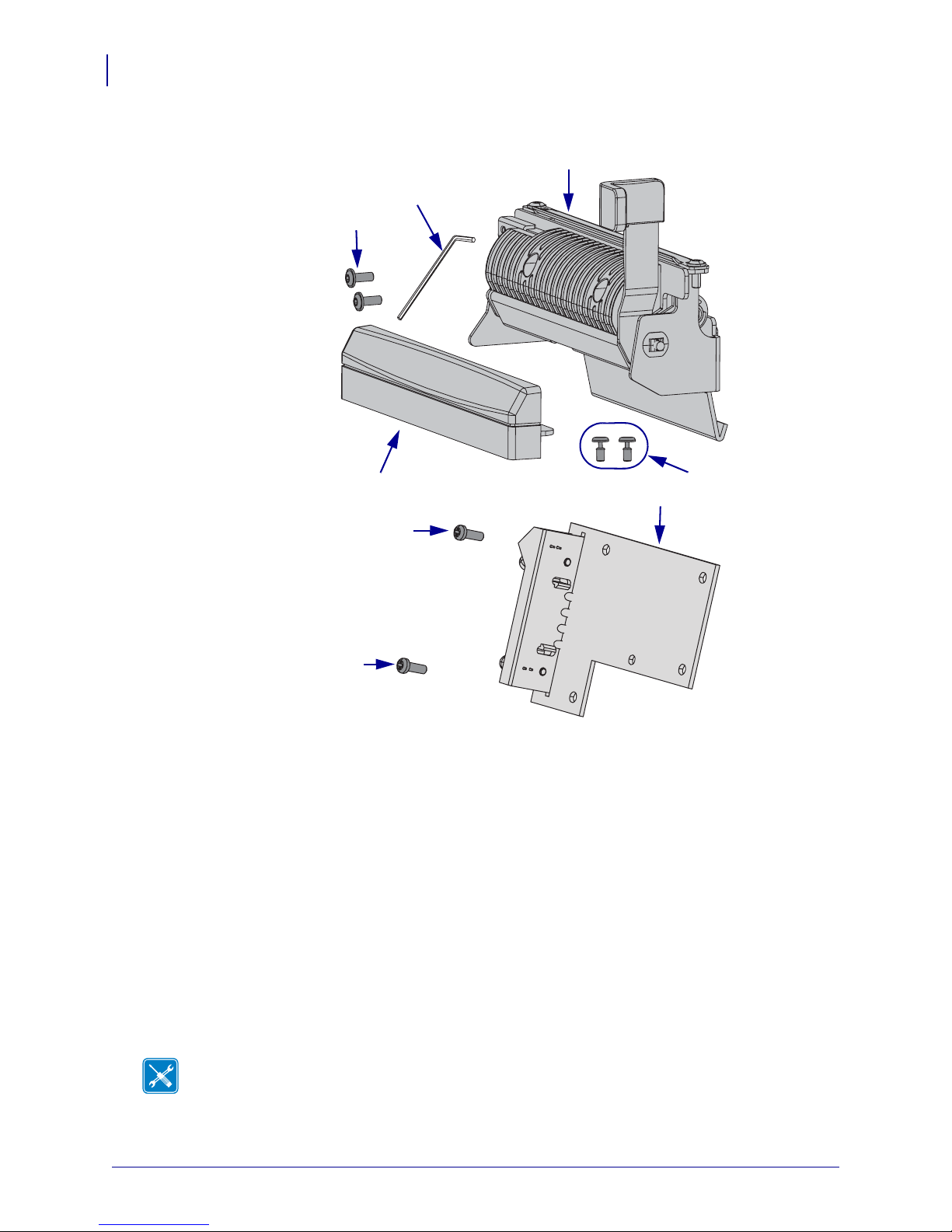
Figure 1 • Kit Contents
1
5
4
Reference Materials
The following manuals and CDs may be helpful references while performing this procedure.
• S4M User Guide
• S4M User Guide CD
• S4M Maintenance Manual (contact your authorized Zebra reseller for purchasing
information)
3
4
4
2
6
• S4M Maintenance Manual CD
Tools Required
Tools •
Phillips Screwdriver Set
Flat-Blade Screwdriver Set
20046L-002 Rev. A S4M Installation Instructions 8/8/06
You need these tools to complete this procedure:
Metric Hex Key (Allen Wrench) Set
Page 3
Remove the Front Cover
1. Turn o ff (O) the printer and remove the AC power cord and data cables.
2. Open the media door and remove the media and ribbon.
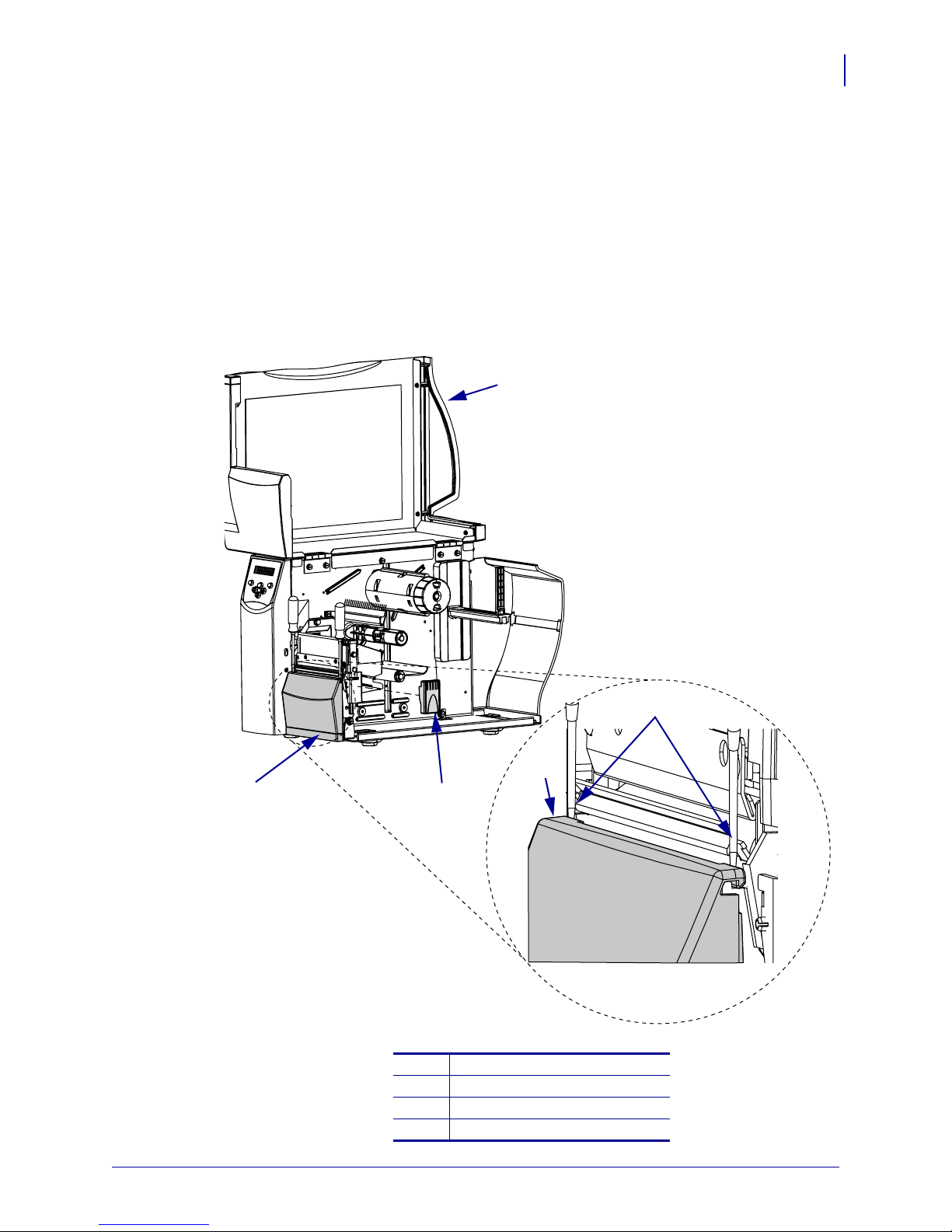
3. See Figure 2. Carefully remove the latch cover.
4. Using a small flat-blade screwdriver, pry the front cover off.
Figure 2 • Remove the Latch and Front Covers
S4M Peel Option Kit
1
3
4
3
3
2
Media door
1
Latch cover
2
Front cover
3
Use flat-blade screwdriver here
4
8/8/06 S4M Installation Instructions 20046L-002 Rev. A
Page 4
S4M Peel Option Kit
4
5. Reinstall the latch cover.
6. Do you have an existing peel option?
If… Then…
No Continue to next step.
Yes Go to Remove the Peel Assembly on page 5.
Remove the Tear Bar
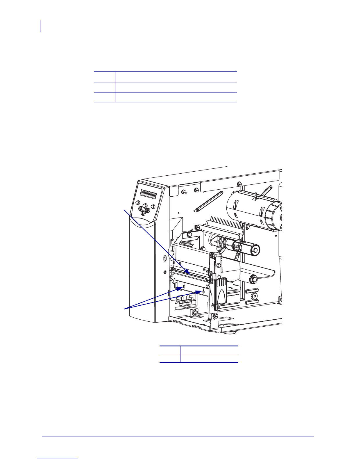
1. See Figure 3. Remove the two tear bar mounting screws.
Figure 3 • Remove the Tear Bar
1
2
1
2
2. Remove and discard the tear bar.
Tear bar
Mounting screws (2)
3. Go to Install the Peel Assembly on page 6.
20046L-002 Rev. A S4M Installation Instructions 8/8/06
Page 5
Remove the Peel Assembly
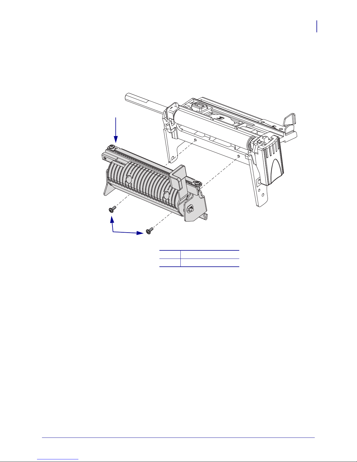
1. See Figure 4. Remove the two mounting screws and then remove the peel assembly.
Figure 4 • Remove Old Peel Assembly
1
S4M Peel Option Kit
5
2
Peel assembly
1
Mounting screws (2)
2
8/8/06 S4M Installation Instructions 20046L-002 Rev. A
Page 6

S4M Peel Option Kit
6
Install the Peel Assembly
1. See Figure 5. Using the hex k ey (Allen wrench) supplie d, instal l the two moun ting screws
from the kit into the tear bar mounting screw holes.
Tighten them to within 1/8 in. of the platen housing.
Figure 5 • Install Peel Assembly
3
1
2
5
6
4
Peel assembly
1
Mounting slots (2)
2
Mounting screws (2)
3
Platen housing
4
Rest pems on housing here
5
Peel lever
6
20046L-002 Rev. A S4M Installation Instructions 8/8/06
Page 7

2. See Figure 6. Notice the pems and the mounting slots.
Figure 6 • Rear View of Peel Assembly
1
S4M Peel Option Kit
7
2
Mounting slots (2)
1
Pems (2)
2
3. See Figure 5 on page 6. Install the peel assembly with the pems to the rear and the opening
in the mounting slot to the top.
a. Insert the mounting slot opening over the two screws and lift up on the assembly.
b. Now, push the assembly back against the vertical surface of the platen housing, then
down, so that the pems are resting on the horizontal surface of the platen housing.
4. Maintain a slight pressure downward on the peel assembly to keep the pems on the
horizontal surface, and tighten the mounting screws.
8/8/06 S4M Installation Instructions 20046L-002 Rev. A
Page 8

S4M Peel Option Kit
8
Install the New Front Cover
1. See Figure 7. Insert the front cover mounting tabs through the mounting holes in the base.
2. Install the two rivets though the two tabs and into the base mounting holes.
Figure 7 • Install the Front Cover
3
4
2
Front cover
1
Push rivets (2)
2
Rivet open
3
Rivet closed
4
3. Reinstall the media and ribbon.
4. Reinstall the AC power cord and data cables.
5. Turn o n (l) the printer.
1
20046L-002 Rev. A S4M Installation Instructions 8/8/06
Page 9

Remove the Electronics Cover
Note • Retain all parts removed during disassembly, unless otherwise directed.
1.
Caution • Tur n o ff (O) the printer and disconnect it from the power source before
performing the following procedure.
Turn o ff (O) the printer and disconnect the AC power cord and all data cables.
2. See Figure 8. Remove the electronic s cover mounting screw and washer and then close the
media door.
Figure 8 • Remove the Mounting Screw
S4M Peel Option Kit
1
9
Media door
1
Electronics cover upper flange
2
Electronics cover mounting screw
3
Washer
4
2
3
4
8/8/06 S4M Installation Instructions 20046L-002 Rev. A
Page 10

S4M Peel Option Kit
10
3. See Figure 9. Remove the four remaining mounting screws securing the electronics cover.
4. Remove the electronics cover by lifting straight up on the bottom lip of the electronics
cover.
Figure 9 • Remove the Electronics Cover
1
2
Electronics cover
1
Mounting screws (4)
2
20046L-002 Rev. A S4M Installation Instructions 8/8/06
Page 11

Remove the Control Panel
Note • Retain all parts removed during disassembly, unless otherwise directed.
1.
Caution • Observe proper electrostatic safety precautions when handling
static-sensitive components such as circuit boards and printheads.
Connect yourself to an antistatic device.
2. See Figure 10. Disconnect the con trol pa nel ribbon cable from J2 on the main logic board
(MLB).
3. If installed, remove the take-label sensor cable from J19 on the MLB and then remove it
from the conduit.
Figure 10 • Remove and Install the Control Panel
S4M Peel Option Kit
11
1
Main frame
1
Main logic board (MLB)
2
J19, Take-label sensor
3
Control panel cable
4
J2, Control panel
5
Mounting screw
6
Split washer
7
5
12
6
8
7
11
2
3
4
13
Star washer
8
Control panel
9
Tab
10
Cable access hole
11
Access hole
12
Conduit
13
9
10
4. Remove the mounting screw and washers securing the control panel.
5. Tip the top of the control panel away from the main frame enough to release the two tabs
inserted into the base mounting slots and then pull it out of the base.
8/8/06 S4M Installation Instructions 20046L-002 Rev. A
Page 12

S4M Peel Option Kit
12
6. Carefully guide the control panel cable and the take-label sensor cable, if installed,
through their access holes.
7. Are you replacing a defective take-label sensor?
If... Then...
Yes Continue with the next step.
No Go to Install the Take-Label Sensor Board on page 13.
Remove the Take-Label Sensor Board
1. See Figure 11. Locate the take-label sensor board on the control panel.
2. Remove and discard the mounting screws and then lift the board out of the control panel
and discard it.
Figure 11 • Remove and Install the Take-Label Sensor
1
2
Take-label sensor board
1
Mounting screws (2)
2
20046L-002 Rev. A S4M Installation Instructions 8/8/06
Page 13

Install the Take-Label Sensor Board
1. See Figure 12 and Figure 13. Align the take-label sensor board with the two guide posts
and install it on the posts, ensuring the posts are inserted in the board.
Figure 12 • Install the Take-Label Sensor Board
1
2
3
S4M Peel Option Kit
13
4
Control panel
1
Take-label sensor board
2
Mounting screws (2)
3
Guide posts (2)
4
8/8/06 S4M Installation Instructions 20046L-002 Rev. A
Page 14

S4M Peel Option Kit
14
Figure 13 • Install the Take-Label Sensor Board on the Mounting Posts
1
Mounting posts (2)
1
Screw holes (2)
2
2. Install the two mounting screws supplied in the kit.
2
20046L-002 Rev. A S4M Installation Instructions 8/8/06
Page 15

Reinstall the Control Panel
1. Tip the top of the control panel away from the main frame and insert the two tabs in the
mounting slots in the base.
Figure 14 • Install the Control Panel in the Base
3
1
4
6
S4M Peel Option Kit
5
15
2
2
1
3
Base
1
Control panel
2
Notch
3
Ta bs (2)
4
Access holes (2)
5
Slots (2)
6
2. See Figure 10 on page 11. Guide the control panel cable through the access hole in the
front of the main frame. Connect it to J2 on the MLB.
3. Guide the take-label sensor cable around and through the lower access hole in the main
frame.
8/8/06 S4M Installation Instructions 20046L-002 Rev. A
Page 16

S4M Peel Option Kit
16
4. Route the take-label sensor cable through the conduit and then connect it to J19 on the
MLB.
5. See Figure 14. Tip the top of the control panel toward the main frame. Ensure that the
take-label sensor cable is in the notch in th e control panel and between the main frame and
the platen roller housing leg.
6. See Figure 10 on page 11. Install the screw and washer to secure the control panel to the
main frame.
Reinstall the Electronics Cover
1. See Figure 9 on page 10. Install the cover by aligning it and sliding down, ensuring that
the lower tabs are inside the base and that the upper flanges are between the main frame
and the media door.
2. Install the four mounting screws on the back of the printer.
3. See Figure 8 on page 9. Open the media door and install the mounting screw and washer
to secure the electronics cover.
4. Reinstall the media and ribbon.
5. Reconnect the AC power cord and data cables.
6. Turn o n (l) the printer.
Select the Peel Mode
1. Press MENU to enter the Setup Mode.
2. Use the left or right arrow to scroll through the parameters until REMOVAL is displayed.
3. Use the up or down arrow until PEEL is displayed.
4. Press MENU.
The printer displays SAVE CHANGES and activates the
5. Press ENTER.
The printer saves changes and exits Setup mode.
ENTER button.
20046L-002 Rev. A S4M Installation Instructions 8/8/06
 Loading...