

Page 1

FX9500
RFID Reader
USER GUIDE
Page 2

Page 3

FX9500 User Guide
72E-150900-09
Revision A
July 2017
Page 4

ii FX9500 RFID Reader User Guide
No part of this publication may be reproduced or used in any form, or by any electrical or mechanical means,
without permission in writing from Zebra. This includes electronic or mechanical means, such as photocopying,
recording, or information storage and retrieval systems. The material in this manual is subject to change
without notice.
The software is provided strictly on an “as is” basis. All software, including firmware, furnished to the user is on
a licensed basis. Zebra grants to the user a non-transferable and non-exclusive license to use each software
or firmware program delivered hereunder (licensed program). Except as noted below, such license may not be
assigned, sublicensed, or otherwise transferred by the user without prior written consent of Zebra. No right to
copy a licensed program in whole or in part is granted, except as permitted under copyright law. The user shall
not modify, merge, or incorporate any form or portion of a licensed program with other program material, create
a derivative work from a licensed program, or use a licensed program in a network without written permission
from Zebra. The user agrees to maintain Zebra’s copyright notice on the licensed programs delivered
hereunder, and to include the same on any authorized copies it makes, in whole or in part. The user agrees not
to decompile, disassemble, decode, or reverse engineer any licensed program delivered to the user or any
portion thereof.
Zebra reserves the right to make changes to any software or product to improve reliability, function, or design.
Zebra does not assume any product liability arising out of, or in connection with, the application or use of any
product, circuit, or application described herein.
No license is granted, either expressly or by implication, estoppel, or otherwise under any Zebra Technologies
Corporation, intellectual property rights. An implied license only exists for equipment, circuits, and subsystems
contained in Zebra products.
Zebra and the stylized Zebra head are trademarks of ZIH Corp., registered in many jurisdictions worldwide. All
other trademarks are the property of their respective owners.
Zebra Technologies Corporation
Lincolnshire, IL U.S.A.
http://www.zebra.com
Warranty
For the complete Zebra hardware product warranty statement, go to:
http://www.zebra.com/warranty.
Page 5

Revision History
Changes to the original manual are listed below:
Change Date Description
-01 Rev A 7/2011 Initial release
-02 Rev A 10/2011 Add instructions to change password.
-03 Rev A 1/2012 Update Set Regulatory Mode.
-04 Rev A 8/2012 Correct storage temperature. Remove Connecting to Serial Port and Connecting
-05 Rev A 7/2013 Add: EMDK Toolkits in Related Document and Software section; GPIO section
iii
to USB Port. Remove User Application Management. Add important note in
chapter 2 and Appendix B regarding connecting the antenna and ensuring that
the reader is Not Transmitting RF Signals. Add notes regarding the following:
Motorola does not support embedded applications/scripts; FX9500 supports only
host based applications. Add GPIO Connections. Remove Chapter
5:Configuring Inputs and Outputs.
figures; Programming for the FX9500 chapter.
Removed: References to USB and RS-232 interfaces; references to Embedded;
Import Security Keys.
-07 Rev A 3/2015 Zebra re-branding
-08 Rev A 8/2016 Updated Figure 4-4.
-09 Rev A 7/2017 Correction on page 2-2.
Page 6

iv FX9500 RFID Reader User Guide
Page 7

Table of Contents
Warranty ........................................................................................................................ ii
Revision History............................................................................................................. iii
About This Guide
Introduction .................................................................................................................... ix
Configurations................................................................................................................ ix
Chapter Descriptions ..................................................................................................... x
Notational Conventions.................................................................................................. xi
Related Documents and Software ................................................................................. xi
Service Information........................................................................................................ xii
Chapter 1: Getting Started
Introduction ................................................................................................................... 1-1
RFID Reader Hardware ................................................................................................ 1-2
Reader Software ........................................................................................................... 1-4
RFID Reader Web Console .................................................................................... 1-4
Chapter 2: RFID Reader Installation
Introduction ................................................................................................................... 2-1
Mechanical Installation ................................................................................................. 2-1
Mounting the RFID Reader ..................................................................................... 2-1
Mounting the Antennas ........................................................................................... 2-2
Electrical Installation ..................................................................................................... 2-3
Connecting and Configuring the Ethernet Port ....................................................... 2-3
Connecting the Antennas ........................................................................................ 2-4
Connecting Digital Inputs/Outputs .......................................................................... 2-5
Connecting the Power ............................................................................................. 2-5
Page 8

vi FX9500 RFID Reader User Guide
Chapter 3: RFID Reader Operation
Introduction ................................................................................................................... 3-1
RFID Reader Operation with Web Console .................................................................. 3-1
Change Password ................................................................................................... 3-3
Chapter 4: Reader Web Console
Introduction ................................................................................................................... 4-1
Web Console ................................................................................................................ 4-1
Basic Configuration ....................................................................................................... 4-2
Configuration Page Header ......................................................................................... 4-2
Manage Profiles ...................................................................................................... 4-3
Set Tag Protocol ........................................................................................................... 4-4
Setup Ethernet/LAN ................................................................................................ 4-5
Setup Digital Accessories ....................................................................................... 4-6
Setup Antenna/Cables ............................................................................................ 4-7
Set Regulatory Mode (Region) ............................................................................... 4-8
Setup Summary ...................................................................................................... 4-9
Advanced Functions ..................................................................................................... 4-10
Firmware Management ........................................................................................... 4-10
Import/Export Configuration .................................................................................... 4-11
Command Line ........................................................................................................ 4-12
Expert Configuration ............................................................................................... 4-12
Expert Configuration - Version ................................................................................ 4-15
Expert Configuration - Information .......................................................................... 4-15
Expert Configuration - Communication ................................................................... 4-16
Expert Configuration - Antennas ............................................................................. 4-18
Expert Configuration - Digital I/O ............................................................................ 4-18
Expert Configuration - Modem ................................................................................ 4-20
Change Operating Mode .............................................................................................. 4-21
View Tags ..................................................................................................................... 4-22
Check Reader Status .................................................................................................... 4-23
Review Logs ................................................................................................................. 4-24
Chapter 5: Configuring Digital Inputs and Outputs
Introduction ................................................................................................................... 5-1
Digital Inputs ................................................................................................................. 5-1
Digital Outputs .............................................................................................................. 5-1
Digital I/O Hardware Connection .................................................................................. 5-2
FX9500 GPIO Connections .......................................................................................... 5-3
Chapter 6: Programming for FX9500
Introduction ................................................................................................................... 6-1
Programming for the FX9500 ....................................................................................... 6-1
Page 9

Appendix A: Technical Specifications
Introduction ................................................................................................................... A-1
Reader Specifications ................................................................................................... A-1
Environmental Specifications ........................................................................................ A-2
Power Supply Specifications ........................................................................................ A-2
Digital Input/Output Specifications ................................................................................ A-3
Ethernet LAN Specifications ......................................................................................... A-3
.FX9500 Antenna Specifications ................................................................................... A-4
Appendix B: Safety Instructions
Power Disconnect Device ............................................................................................. B-1
RF Safety ..................................................................................................................... B-1
Electrostatic Discharge ................................................................................................. B-1
Regulatory Compliance ................................................................................................ B-2
Appendix C: Disposal of Reader
Table of Contents vii
Index
Page 10

viii FX9500 RFID Reader User Guide
Page 11

About This Guide
Introduction
This document is intended for those who wish to setup and operate the FX9500 RFID Reader system. Before
attempting to install, configure, and operate this product, you should be familiar with the following:
•
Windows-based software installation and operation
•
Device communication parameters including Ethernet and serial communications
•
RFID reader configuration including antenna placement
•
Basic digital input/output control.
NOTE Screens and windows pictured in this guide are samples and may differ from actual screens.
Configurations
This guide covers the following FX Series of RFID reader configurations:
•
US and Canada 4-port configuration, part number: FX9500-41324D41-US
•
International 4-port configuration, part number: FX9500-41324D41-WW
•
US and Canada 8-port configuration, part number: FX9500-81324D41-US
•
International 8-port configuration, part number: FX9500-81324D41-WW.
Page 12

x FX9500 RFID Reader User Guide
Chapter Descriptions
Topics covered in this guide are as follows:
•
Chapter 1, Getting Started - This chapter provides a brief overview of the FX9500 RFID Reader hardware
and software.
•
Chapter 2, RFID Reader Installation - This chapter describes how to mechanically and electrically install the
FX9500 RFID Reader.
•
Chapter 3, RFID Reader Operation - This chapter provides the FX9500 RFID Reader operation instructions.
•
Chapter 4, Reader Web Console - This chapter provides information on how to fully configure the FX9500
RFID Reader for operation in a variety of applications and environments.
•
Chapter 5, Configuring Digital Inputs and Outputs - This chapter provides information on how to configure the
FX9500 RFID Reader Digital Inputs and Outputs.
•
Chapter 6, Programming for FX9500 - This chapter provides information on programming for the FX9500
RFID Reader.
•
Chapter A, Technical Specifications - This appendix provides detailed mechanical, electrical, and
environmental specifications.
•
Chapter B, Safety Instructions - This appendix provides important safety information about the FX9500 RFID
Reader. All users must read this section before installing or operating this reader.
•
Chapter C, Disposal of Reader - This appendix provides instruction for removing the battery and disposing of
the reader.
Page 13

Notational Conventions
The following conventions are used in this document:
•
“RFID Reader” or “reader” refers to the FX9500 RFID reader.
•
Italics are used to highlight the following:
• Chapters and sections in this guide
• Related documents.
•
Bold text is used to highlight the following:
• Code entered by the user
• Dialog box, window and screen names
• Drop-down list and list box names
• Check box and radio button names
• Icons on a screen
• Key names on a keypad
• Button names on a screen.
About This Guide xi
•
Bullets (•) indicate:
• Action items
• Lists of alternatives
• Lists of required steps that are not necessarily sequential.
•
Sequential lists (e.g., those that describe step-by-step procedures) appear as numbered lists.
•
Values in () indicate:
• (values) within parentheses indicate parameters
• (values) in italics indicate user defined variables.
•
<n> indicates a variable number used in a function that can apply to several different devices such as
antennas or I/O ports.
Related Documents and Software
The following documents provide more information about the FX9500 RFID reader.
•
FX9500 Regulatory Guide, p/n 72-152143-xx
•
Zebra EMDK Toolkits (see the FX9500 product web page on the Zebra Support site).
For the latest version of this guide and all guides, go to: www.zebra.com/support.
Page 14

xii FX9500 RFID Reader User Guide
Service Information
If you have a problem with your equipment, contact Zebra support for your region. Contact information is available
at: www.zebra.com/support.
When contacting Zebra support, please have the following information available:
•
Serial number of the unit
•
Model number or product name
•
Software type and version number
Zebra responds to calls by e-mail, telephone or fax within the time limits set forth in service agreements.
If your problem cannot be solved by Zebra support, you may need to return your equipment for servicing and will
be given specific directions. Zebra is not responsible for any damages incurred during shipment if the approved
shipping container is not used. Shipping the units improperly can possibly void the warranty.
If you purchased your business product from a Zebra business partner, please contact that business partner for
support.
Page 15

Chapter 1 Getting Started
Introduction
This chapter provides a brief overview of the FX9500 RFID Reader hardware and software.
Page 16

1 - 2 FX9500 RFID Reader User Guide
Mounting Tab
Mounting Tab
LEDs
Antenna 1-8 (Rx/Tx)
Ethernet
(TCP-IP)
(Digital)
GPIO
Power
Reset
RFID Reader Hardware
The FX9500 RFID Reader is a multi-protocol, multi-regional Radio Frequency Identification (RFID) System that
operates in the 902-928 MHz and 865-868 MHz band.
Figure 1-1
FX9500 RFID Reader
Page 17

Getting Started 1 - 3
As shown in Figure 1-2, the high performance FX9500 RFID Reader supports up to eight Tx/Rx antennas (8x1
monostatic or 4x2 bistatic) and Ethernet interfaces. Discrete digital inputs and outputs are also provided.
Figure 1-2
FX9500 Power and I/O Connections
NOTE The eight (8) port FX9500 RFID Reader illustrated above also is available in a four (4) port
configuration (see Configurations on page 3-ix).
The FX9500 RFID Reader is equipped with four status indicators located on the top of the enclosure. These LEDs
provide indication for the following:
.
Figure 1-3
Table 1-1
FX9500 RFID Reader Status Indicators
FX9500 RFID Reader Indication Definitions
Number Indication Color/State Indication
1 Power Off
Amber
Amber-Flashing
Green
2 Activity Off
Green
Green-Flashing
Amber
Power off
Boot loader executing
Linux initializing
Unit operational
RF off
TX active
Tag detect
Antenna check failed
3 User Amber User defined
4 Status Off
Amber
Green-Flashing
Red
OK
Firmware update
GPIO activity
Fault
Page 18

1 - 4 FX9500 RFID Reader User Guide
Reader Software
The FX9500 is shipped with a software application that can be used to configure and control the RFID Reader.
RFID Reader Web Console
The Web Console is a RFID Reader application that provides the ability to access RFID Readers across the
internet. Enter the IP address of the RFID Reader into a web browser, Web Console and RM interface allows you
to fully modify and operate the RFID Reader. This application provides the ability to modify the RFID Reader's
communication, network, and operational parameters. Also, the ability to read tags, review tag data, perform
diagnostics, and upload new software. This application is primarily intended for configuring and managing
deployed RFID Readers. For detailed information, see Chapter 4, Reader Web Console.
Page 19

Chapter 2 RFID Reader Installation
Introduction
This chapter describes how to mechanically and electrically install the FX9500 RFID Reader.
Mechanical Installation
Mounting the RFID Reader
The FX9500 is equipped with two mounting flanges and slotted keyholes that accept three #8 (M4) mounting
screws. Pre-drill mounting surface according to the following dimensions. The mounting surface must be able to
support up to 5 pounds (2.3 kg).
Figure 2-1
FX9500 Mechanical Dimensions (dimensions in mm)
Page 20

2 - 2 FX9500 RFID Reader User Guide
Concrete Wall Mounting
To mount the RFID Reader to a hollow concrete block wall, Zebra recommends metal sleeve type concrete
anchors that accept #8 screws and flat washers.
Wood or Metal Wall Mounting
To mount the RFID Reader to a wood or sheet metal wall, Zebra recommends either #8 x 1 inch wood screws or #8
x 1 inch sheet metal screws and washers.
Drywall Mounting
To mount the RFID Reader to drywall or sheetrock, Zebra recommends either #8 toggle bolts or #8 drywall
anchors.
Mounting the Antennas
The FX9500 RFID Reader supports from one to eight antennas in a variety of configurations. One and two-antenna
configurations are typical for most conveyor and container tracking. Four and eight antenna configurations are
used for portals and loading dock doorways.
Antennas (not provided) must be installed on a solid surface or frame to prevent damage or later misalignment. It
is highly recommended that the antenna mounting be adjustable in order to obtain the best performance from the
system.
WARNING! FCC Radiation Exposure Statement. The antennas used for this transmitter must be installed
to provide a separation distance of at least 25 cm from all persons and must not be co-located
or operating in conjunction with any other antenna or transmitter.
EU Radiation Exposure Statement. The antennas used for this transmitter must be installed to
provide a separation distance of at least 25 cm from all persons and must not be co-located or
operating in conjunction with any other antenna or transmitter.
Page 21

Electrical Installation
RFID Reader Installation 2 - 3
Figure 2-2
FX9500 Electrical Connections
NOTE The FX9500 RFID Reader is designed to meet the regulatory requirements in those
jurisdictions in which it is offered. Changes or modifications not expressly approved by Zebra
for compliance could void the user's authority to operate the equipment.
IMPORTANT FX9500 RFID Reader antenna ports may be susceptible to damage from static discharge
or other high voltage. Use proper Electrostatic Discharge (ESD) precautions to avoid static
discharge when handling or making connections to the FX9500 RFID Reader antenna or
communication ports. Equipment failure can result if the antenna or communication ports
are subjected to ESD.
Connecting and Configuring the Ethernet Port
The maximum Ethernet cable length is 30 meters. If communicating with the RFID Reader across a Local Area
Network (LAN), connect an Ethernet cable from the hub or router to the RJ-45 connection.
By default, the RFID Reader is configured to use a DHCP server to obtain its IP address and related information. In
the event a DHCP server is unavailable, the RFID Reader will boot with an IP address in the 169.254.x.x subnet.
In the absence of other RFID Readers on the same network, and if no other network traffic is observed which
references 169.254.1.1, the RFID Reader will select that address; otherwise, it will select a random address on the
169.254.x.x subnet.
Page 22

2 - 4 FX9500 RFID Reader User Guide
Connecting the Antennas
The maximum antenna cable length is 10 meters. Connect the antenna to antenna port 1. If using additional
antennas, connect them to Ports 2-8.
Antennas can be connected as either 8x1 monostatic or 4x2 bistatic.
IMPORTANT Always stop RF reading/polling on the RFID reader through the web console before
removing an antenna or load from an RF port.
NOTE The FX9500 RFID Reader antenna ports may be susceptible to damage from static discharge
or other high voltage. Use proper Electrostatic Discharge (ESD) precautions to avoid static
discharge when handling or making connections to the FX9500 RFID Reader antenna or
communication ports. Equipment failure can result if the antenna or communication ports are
subjected to ESD.
NOTE None of the GPIO connector pins on the FX9500 RFID reader provide voltage to drive external
devices. When using the GPIO connector on the FX9500, you must provide power to drive the
GP inputs and to power any devices driven by the GP outputs. GP outputs are pulled low when
activated and can conduct enough current to drive a load of up to 1W from a positive supply
that must not exceed 40V.
Page 23

RFID Reader Installation 2 - 5
Connecting Digital Inputs/Outputs
The FX9500 RFID Reader is equipped with a general purpose digital input/output (I/O) port that provides four
optically isolated 5-24 Vdc input signals and four open-collector output signals. The digital inputs can be used as
general purpose inputs or to trigger the RFID Reader for tag reading. These inputs can be configured to provide an
external read trigger from proximity sensors, photo switches, or other devices.
The digital outputs can be used as general purpose outputs, to indicate tag reading activity, or to indicate the RFID
Reader is transmitting (RF On). The outputs can also be configured to trigger conveyor gates or other access
control and sorting devices. For detailed information on configuring the digital inputs and outputs, see Chapter 5,
Configuring Digital Inputs and Outputs.
Figure 2-3
Digital Input/Output
Connecting the Power
Connect the 24 Vdc power supply to the RFID Reader and connect the power supply to your 100-240 Vac, 50-60
Hz power source. Allow 30 seconds for the RFID Reader to initialize.
Page 24

2 - 6 FX9500 RFID Reader User Guide
Page 25

Chapter 3 RFID Reader Operation
Introduction
This chapter provides operation instructions for the FX9500 RFID Reader.
RFID Reader Operation with Web Console
The FX9500 can be operated by logging directly into the RFID Reader’s Web Console. To access a particular RFID
Reader, perform the following:
1. Enter the RFID Reader's IP address into your web browser or press the Configure button.
2. The RFID Reader's Web Console interface is displayed.
Figure 3-1
Web Console Interface Screen
Page 26

3 - 2 FX9500 RFID Reader User Guide
3. Log into the RFID Reader. Press Login for the login screen.
Figure 3-2
4. The default login is guest. If you need administrator privileges, login as admin and enter change as the
Login Screen
password.
5. Press Submit.
6. Select Basic Configuration, then Setup Antenna/Cables to configure the antennas, gain, and power
settings.
7. Select Advanced Functions, then Change Operating Mode to verify the RFID Reader is in the proper mode.
8. Select Basic Configuration, then Set Tag Protocol to verify the RFID Reader is configured for the proper tag
protocol.
9. Press System Status, then View Tags to view tag data.
Figure 3-3
10. If you need to configure your RFID Reader, see Chapter 4, Reader Web Console for information on using Web
View Tag Data Screen
Console to adjust configuration variables and parameters.
Page 27

Reader Operation 3 - 3
Change Password
The reader.set_pwd()command is used to change the password. This command requires the following
parameters:
•
Login (level for password to be changed)
•
Pwd (existing password for the login level)
•
New_pwd (new password for the login level).
The login and existing password are required to change the password. For example, to change the initial
password for the guest login level to 19qht34 use the following command:
> reader.set_pwd(guest,readerguest,19qht34)
ok
NOTE To prevent unauthorized reader access, it is strongly recommended that the default guest login
and admin password are changed.
Page 28

3 - 4 FX9500 RFID Reader User Guide
Page 29

Chapter 4 Reader Web Console
Introduction
This chapter provides information on how to fully configure the FX9500 RFID Reader for operation in a variety of
applications and environments.
Web Console
The Reader Web Console allows access to a RFID Reader across the Internet by entering the Reader's IP address
into the web browser. With the Web Console, the RFID Reader can fully be configured for operation in a variety of
applications and environments. The following options are available in this application:
•
Basic Configurations
•
Advanced Configurations
•
Check System Status
•
Access the online Help.
Figure 4-1
Web Console Interface Screen
Page 30

4 - 2 FX9500 RFID Reader User Guide
Basic Configuration
With the Basic Configuration functions you can perform the following:
•
Manage reader profiles
•
Set tag protocols
•
Setup the Ethernet/LAN configuration
•
Setup the serial port
•
Setup digital accessories
•
Setup antennas
•
Set regulatory modes.
Configuration Page Header
Each page displayed by the Web Console has the following header.
Figure 4-2
This header provides pull-down menus for each of the configuration function categories. Additional functions
include the user login and the currently loaded reader profile.
Web Console Header
Login
The reader's default user level is guest. However, a user can login as admin. If not logged in as admin, the default
level is always guest.
The guest login level provides read-only access to the reader. Clients that login in at the guest level can read the
settings of the reader and can access the tags that the reader has inventoried. Clients at this level cannot change
the configuration of the reader.
The admin login level provides read-write access to the reader. Clients that login in at the admin level can read and
write the settings of the reader and can access the tags that the reader has inventoried.
Logout
After logging in as admin, the Logout button logs out of the reader. Logging out automatically sets the login level
to guest.
Profile
Profile is the currently active profile in the reader (see Manage Profiles on page 4-3 for detailed information on
reader profiles).
Save
The Save button saves the reader's current configuration to the specified profile (see Manage Profiles for detailed
information on reader profiles).
Manage Profiles
The Manage Profiles link lists, saves, and deletes profiles. Refer to the Manage Profiles section for detailed
information on reader profiles.
Page 31

Manage Profiles
The reader's configuration is stored in a profile. A profile contains the setting of all
the configuration variables in the reader. The reader can support up to 8 unique
profiles.
The Manage Profiles page provides a list of all profiles stored in the reader.
Reader Web Console 4 - 3
Figure 4-3
Manage Profiles Page
Save a Profile
To save the current reader configuration under a new profile, enter a profile name and press Save. The new profile
will appear in the Profile Name list. Profile names must consist of the characters A - Z, a - z, 0 - 9, '-' or '_' and must
be between 1 and 32 characters in length. The reader can store up to 8 different profiles.
NOTE The profile name factory is reserved and cannot be used. This profile is a read only profile.
Activate a Profile
To activate a previously saved profile, press the Activate button beside the profile name. The selected profile will
be loaded into the reader.
Delete a Profile
To delete a previously saved profile, press the Delete button beside the profile name. Once a profile is deleted, it
cannot be recovered.
IMPORTANT Deleting a profile is a destructive operation. Profiles cannot be recovered once they have
been deleted.
Page 32

4 - 4 FX9500 RFID Reader User Guide
Set Tag Protocol
The Set Tag Protocol page consists of two forms. The first form (top) allows you
to select which type of tags the reader will acquire or the type of protocol(s) to
utilize on the air interface. Zebra supports only ISO 180006C(ISOC) also known
as, EPC Global Class 1 Gen2 operation on the FX9500 reader.
Figure 4-4
Select the check box for the protocol(s) to enable and then press Enable Selected Protocols to activate the
protocol.
Click on a specific protocol to view the lower form. This form allows you to configure various protocol level
parameters. The protocol level parameters are divided into two categories: Control and Physical. Control
parameters configure the protocol control. Physical parameters configure the physical air interface for the
protocol.
Set Tag Protocol Screen
Figure 4-5
Control Protocol/Physical Protocol Screens
Page 33

Setup Ethernet/LAN
Reader Web Console 4 - 5
The Setup Ethernet/LAN page configures the network interface of the reader.
Figure 4-6
NOTE Always record and keep the following items in a safe location: IP, Mac, subnet, and default
Setup Ethernet/LAN Screen
gateway addresses. This data can be used to reconfigure the network in the event of
application failure or data loss.
Page 34

4 - 6 FX9500 RFID Reader User Guide
General Settings
General Settings specify the host and domain name of the reader. Also, the Command Port and Event Port are
shown and are read-only.
IPv4/IPv6 Settings
IPv4/IPv6 Settings configure the reader's IP address. If the reader is to automatically acquire its IP address,
subnet mask and default gateway from a DHCP server, select Enable DHCP. To manually specify this information,
deselect Enable DHCP and fill in the desired IP address, subnet mask and default gateway.
Other Settings
Other Settings offer the ability to configure the NTP servers the reader can contact to obtain the current time,
DNS servers the reader can contact for domain name resolution, and the Domain list to resolve names to IP
addresses.
Enter all the required information and press Submit.
Setup Digital Accessories
The Setup Digital Accessories function configures the Digital Inputs and Outputs
on the reader.
Figure 4-7
Setup Digital Accessories Screen
Page 35

Reader Web Console 4 - 7
Digital Input
The status of the four digital input values (1-4) can be seen in this window. The Current Value is not configurable
and is shown as true or false. The Debounce value can be set and is in milliseconds.
Digital Output
The output value for each digital output can be set to true or false. Press the Submit button to send the
appropriate commands to the reader.
Setup Antenna/Cables
Use this option to configure the reader's antenna multiplexer sequence as well as,
conducted power.
To configure an antenna, enter the antenna number in the Mux Sequence field.
The individual antenna Conducted Power fields will be activated in the lower
window. The current values will be displayed. Only those antennas listed in the
Mux Sequence will be shown. Also, you must set Conducted Power to 0 in order
to set or change the Attenuation, Cable Loss, or Gain.
To change, enter the appropriate values for each antenna parameter and press the
Submit button to update the antenna and cable configuration. Select the next antenna and repeat.
Figure 4-8
Antenna/Cable Setup Screen
Page 36

4 - 8 FX9500 RFID Reader User Guide
Set Regulatory Mode (Region)
Use this mode to configure the reader to meet the regulatory requirements for the
geographic region where the reader is deployed. The sub-region sets the
secondary regulatory mode for the geographic region where the reader is
deployed.
Figure 4-9
Select your Region.
Regulatory Mode Screen
IMPORTANT Select only the country in which you are using the device. Any other selection will make
the operation of this device illegal.
Figure 4-10
Regulatory Mode - Select Region
Page 37

Select the Sub Region.
Reader Web Console 4 - 9
Figure 4-11
Regulatory Mode - Select Sub Region
Page 38

4 - 10 FX9500 RFID Reader User Guide
Setup Summary
Quickly setup the basic operational parameters of the reader in Setup Summary.
Figure 4-12
Setup Summary Screen
Page 39

Advanced Functions
Firmware Management
Use the Firmware Management option to read the current firmware version, upgrade the reader firmware files, or
rollback to the previous firmware version.
Reader Web Console 4 - 11
The following options are available in Advanced Functions:
•
Firmware Management
•
Import/Export Configuration
•
Command Line operations
•
Expert Configuration
•
User Application Management
•
Change Operating Mode
•
Restart.
To upgrade reader firmware, enter the name of the Zebra provided firmware file in the Firmware File field. Use the
Browse button to help locate the file. Once the filename is entered, press Upgrade Firmware.
The same method is used to upgrade the LLRP Component firmware. Use the Browse button to help locate the
file. Once the filename is entered, press Update Component.
The Rollback Firmware button will roll back the firmware to the previous version.
Figure 4-13
Firmware Management Screen
Page 40

4 - 12 FX9500 RFID Reader User Guide
Import/Export Configuration
This option transfers a reader configuration to or from a host computer. This is useful for configuring a reader to a
known state.
Transfer a Configuration File
Enter the name of a saved configuration file in the Configuration file field. Select the XML File option and press
the Transfer Configuration to Reader button to send the profile to the reader.
Export Configuration File to Reader
This function is used to export the current reader settings for later uploading. Press the XML Format button to view
the XML file in the browser. To retain the file for future reference, save the file.
To view the current configuration parameters for a reader, press Text Format button.
NOTE The Import License feature is not supported. Therefore, disregard the Import License section
shown in Figure 4-14.
Page 41

Reader Web Console 4 - 13
Figure 4-14
Import/Export Configuration Screen
Page 42

4 - 14 FX9500 RFID Reader User Guide
Command Line
Use Command Line to directly enter reader commands from a web browser.
Figure 4-15
Command Screen
Expert Configuration
Use the Expert Configuration functions to configure low-level functions within the
reader. These functions should only be accessed by expert users. Expert
configurations include:
•
Setup
•
Tag
•
Version
•
Information
•
Communication
•
Antennas
•
Digital I/O
•
Modem.
Page 43

Reader Web Console 4 - 15
Expert Configuration - Setup
Use Expert Configuration - Setup to set the basic operating parameters of the reader including region, sub
region, mode, and active protocols. Also, view the valid protocols and regions.
Figure 4-16
Expert Configuration Screen
Expert Configuration - Tag
Use the Expert Configuration - Tag option to configure how the reader reports
tags.
The FX9500 supports the ability to filter tags or eliminate tags from being reported
based on the conditions specified in the filter configuration variables. The reader
supports eight filters and each filter is specified by the following configuration
variables:
•
Enabled - Enables or disables the filter.
•
Inclusive - Indicates to either include tags that match (inclusive) or include tags
that do not match (exclusive) the tag filter.
•
Mask - Mask (as an array of hex bytes) for the tag filter.
•
Name - Name given to the tag filter
•
Pattern - Pattern (as an array of hex bytes) for the tag filter.
Page 44

4 - 16 FX9500 RFID Reader User Guide
The following figure shows a small sample of the available variables.
Figure 4-17
Expert Configuration - Tag Screen
Page 45

Expert Configuration - Version
Use Expert Configuration - Version to view the version of hardware and software
within the reader. The version numbers are read-only. Supply the version number
to Zebra Technical Support should they be contacted.
Reader Web Console 4 - 17
Figure 4-18
Expert Configuration - Version Screen
Page 46

4 - 18 FX9500 RFID Reader User Guide
Expert Configuration - Information
Expert Configuration - Information can be used to customize the reader's identity. Use this option to assign each
reader a name, description, and location.
The time setting field indicated by info.time can not be populated using Expert Configuration. To set the time, use
the Command Line to directly enter the time setting command from a web browser. Enter the time command as
follows:
Using a web browser, enter the time command (see Command Line on page 4-12).
>>> info.time=Year(xxxx)-month(xx)-day(xx)Thour(xx):minutes(xx):seconds(xx).milliseconds(xxx)
For example, to set the date to July 26, 2011 and time to 10:50am, 58 seconds and 345 milliseconds, the following
command would be entered in the command field:
>>> info.time=2011-07-26T10:50:58.345
Figure 4-19
Expert Configuration - Information Screen
Page 47
Reader Web Console 4 - 19
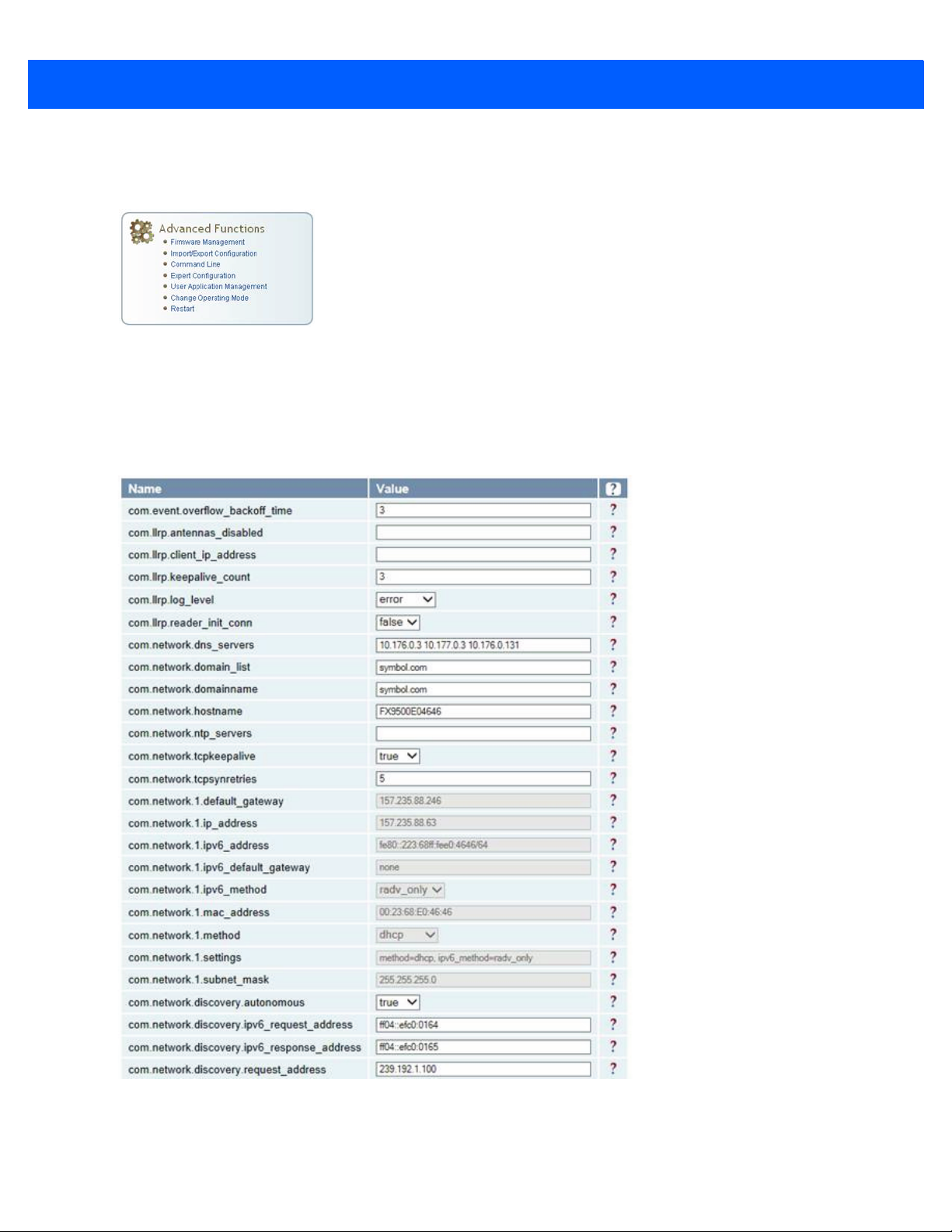
Expert Configuration - Communication
Expert Configuration - Communication is used to customize the reader's
communication parameters.
See Setup Ethernet/LAN on page 4-5 and Setup Digital Accessories on page 4-6
for additional information.
The following figure shows a portion of communication parameters available on the reader, such as:
•
com.llrp.client_ip_address - IP address of LLRP Client
•
com.llrp.keepalive_count - Indicates the non-acknowledge keep alive count
•
com.llrp.log_level - Log level associated with LLRP service.
Figure 4-20
Expert Configuration - Communication
Page 48

4 - 20 FX9500 RFID Reader User Guide
Expert Configuration - Antennas
Use Expert Configuration - Antennas to configure the properties of the reader's
antenna configuration
Enter the appropriate values for each antenna parameter and press the Submit
button to update the antenna and cable configuration.
The following figure shows only a small sample of the available antenna
configuration variables.
Figure 4-21
Expert Configuration - Antenna Screen
Page 49

Expert Configuration - Digital I/O
Use the Expert Configuration - Digital I/O option to configure the digital inputs
and output behavior. Set the digital input debounce time (in milliseconds), as well
as the input and output pin values.
Some of the antenna parameters available on the reader are as follows:
•
antennas.detected - Antenna ports with antennas connected.
•
antennas.max_set_conducted_power - Maximum conducted power for all antennas.
•
antennas.max_computed_conducted_power - Maximum computed conducted power for all antennas.
•
antennas.mux_sequence - Specify a list of antenna ports.
•
antennas.port_count - Number of antenna ports on this reader.
•
antennas.<n>.conducted_power - Transmit power for antenna port.
•
antennas.<n>.advanced.cable_loss - Cable loss on this port.
•
antennas.<n>.advanced.computed_conducted_power - Computed conducted power on this port.
• This parameter is the only parameter from the above that will be persisted when connecting over the
LLRP interface. All other values may be overwritten based on LLRP interface configurations.
Reader Web Console 4 - 21
Figure 4-22
Expert Configuration - Digital I/O Screen
Page 50

4 - 22 FX9500 RFID Reader User Guide
Expert Configuration - Modem
Use the Expert Configuration - Modem option to set the reader's modem control
variables. These variables control functions such as EPC link, modulation depth,
return link frequency, and others. The following figure shows only a small sample
of the available modem configuration variables.
Figure 4-23
NOTE Customer embedded applications are not supported by Zebra.
Expert Configuration - Modern Screen
Page 51

Reader Web Console 4 - 23
Page 52

4 - 24 FX9500 RFID Reader User Guide
Change Operating Mode
Use Change Operating Mode to configure the operational mode of the reader.
Figure 4-24
The reader supports the following operational modes:
•
•
Operating Mode Screen
Active Mode - Reader is continuously attempting to singulate tags and automatically reports any singulated
tag via an asynchronous event notification on the event channel.
Stand By Mode - Reader is not transmitting any energy, unless processing a tag related command. The RF
transmitter is enabled at the beginning of the command processing, protocol operations required for the
command are performed and then the RF transmitter is turned back off.
Page 53

View Tags
Reader Web Console 4 - 25
All tags read by the reader are stored in a database on the reader. Use View Tags
to view the tags in the database as well as change the current Operating Mode
(Active or Stand By).
Press Start to begin displaying the tag database. This page is automatically
refreshed every five seconds. Press Get Once to update the database one time
(refresh is off). Press Purge to purge all tags from the database.
Figure 4-25
Tag Database Display
Page 54

4 - 26 FX9500 RFID Reader User Guide
Check Reader Status
To view the reader status, select Check Reader Status. This information can be
used by Zebra Technical Support to verify reader operation.
Figure 4-26
RFID Reader Status Screen
Page 55

Review Logs
Reader Web Console 4 - 27
To view the reader logs. select Review Logs. These logs can be used by
Technical Support to verify reader operation. The reader logs include:
•
Reader level Logs - System level reader operation
•
System Level Logs - Linux logs
•
Firmware Update Log - System level
•
Reader Applications Log - User application logs
•
Command History Log - Recent commands sent to the reader.
Figure 4-27
Review RFID Reader Logs
Page 56

Chapter 5 Configuring Digital Inputs and Outputs
Introduction
This chapter provides information on how to configure the FX9500 RFID Reader Digital Inputs and Outputs.
Digital Inputs
The digital inputs (DIN1 - DIN4) can be used as general purpose inputs or to trigger the reader for tag reading.
Unused or open digital inputs are floating inside the reader.
To activate the input, pull it low (0 Vdc) with an external device or connection to ground that can sink 2.5 mA. No
voltage higher than +24 Vdc or lower than 0 Vdc should ever be connected to the input. See Figure 5-1 on page
5-2 for an example of a typical motion sensor installed as a tag read trigger device.
Digital Outputs
The digital outputs (DOUT1 - DOUT4) can be used as general purpose outputs, to indicate tag reading activity, or
to indicate the reader is transmitting (RF On). Digital outputs can be pulled high.
No voltage higher than +40 Vdc or lower than 0 Vdc should ever be connected to a digital output. The reader
activates the output by pulling it low (0 Vdc) and can sink current such that power dissipation <
1W.
Page 57

5 - 2 FX9500 RFID Reader User Guide
12-24 Vdc
NO
NC
Motion Sensor
Tag Detection Indicator
12
Digital Output Common
1
Di g i ta l In pu t C o mm o n f o r D IN 1/ D IN 2
2
DIN1 (Dig i tal Input 1)
11 DOUT4 (Digital Output 4)
3 DIN2 (Dig i tal Input 2)
10 DOUT3 (Digital Output 3)
4 Dig ital Input Common for DIN3/DIN4
9 DOUT2 (Digital Output 2)
5 DIN3 (Dig i tal Input 3)
8
DOUT1 (Digital Output 1)
7
Digital Output Common
6 DIN4 (Dig i tal Input 4)
External
DC Supply
(User Supplied)
(VDC)
_
+
RS
5V VDC 40V
(V
DC)
2
/RS
1W
INfinity 510 Digital I /O
12 1
FX9500 Digital I/O
Digital I/O Hardware Connection
The below figure shows a typical sensor/indicator connection to the digital I/Os.
Figure 5-1
Example Motion Detector and Indicator connected to the Digital I/O
Page 58

FX9500 GPIO Connections
123456789
101112
DIN1/
DIN2
REF
DIN1
DIN2
DIN3/
DIN4
REF
DIN3
DIN4
GND
DOUT1
DOUT2
DOUT3
DOUT4
GND
LAMP
LAMP
Note:
DC power supplies in the range 5V to
24V may be suitable provided that they
are compable with light stack and
sensor power requir ements.
Note :
‘NC’ signifies Normally
Closed contact on relay.
‘NO’ idenfies Normally
Open contact on relay.
DC
Power
Supply
V+
V-
+
+
DIN1/
DIN2
REF
DIN1
DIN2
DIN3/
DIN4
REF
DIN3
DIN4
GND
DOUT1
DOUT2
DOUT3
DOUT4
GND
MOTION
SENSOR 1
MOTION
SENSOR 2
NC
NO
NO
NC
VIN
LAMP
+
VIN GND
GND
The GPIO connector pinouts include the following:
•
Four GP outputs (open collector to GND, 0.1 Amp max).
•
Four optically isolated GP inputs (external supply required).
Configuring Digital Inputs and Outputs 5 - 3
Figure 5-2
GPIO Connector Pinouts
The following figure provides an example of a typical setup with light stack and motion sensors.
Figure 5-3
Example of Typical GPIO Setup
Page 59

5 - 4 FX9500 RFID Reader User Guide
Page 60

Chapter 6 Programming for FX9500
Introduction
This chapter provides information on programming for the FX9500 RFID Reader.
Programming for the FX9500
The primary programming interface of the FX9500 RFID reader is via LLRP protocol interface on
TCP port 5084. Applications can be developed for the reader in the following ways:
•
Applications using the RFID3 API set that is a part of the Zebra EMDK.
• The FX9500 RFID reader supports only host based RFID3 APIs for the FX9500.
• The FX9500 RFID reader cannot run embedded RFID3 API based applications.
•
Applications that are written using the LLRP interface directly.
• The FX9500 RFID reader supports only host based LLRP applications for the FX9500.
• The FX9500 RFID reader cannot run embedded LLRP based applications.
The recommended reference guide for the RFID3 API set is included in the Zebra EMDK install available on the
Zebra support site at: http://www.zebra.com/support. There is a Programmers Guide included in the Help section
that contains an introductory guide on how to perform various functions using the RFID3 API set.
Page 61

6 - 2 FX9500 RFID Reader User Guide
Page 62

Appendix ATechnical Specifications
Introduction
This chapter provides detailed mechanical, electrical and environmental information for the FX9500 RFID
Reader.
Reader Specifications
Table A-1
Frequency 902 - 928 MHz (Maximum- some countries truncate this band)
EU Band 865 - 868 MHz
RF Power 10 mW - 1W conducted (Antenna Input - 30 dBm maximum; Reader - 31 dBm)
Power Consumption 10W (typical while idle)
Connections Digital I/O, Ethernet LAN
Input Voltage 24 Vdc, 60W
Input Current 2.5A maximum at 24 Vdc
Reader Specifications
Feature Description
18W (typical at 1W conducted output power)
20W (maximum at 1W conducted output power)
Page 63

A - 2 FX9500 RFID Reader User Guide
Figure A-1
Typical Power Consumption versus Conducted Output Power at 910 MHz
Environmental Specifications
Table A-2
Operating Temperature 4° F to 131° F (-20° C to 55° C)
Storage Temperature 40° F to 185° F (-40° C to 85° C)
Maximum Shock 1 foot (0.3 meter) drop to any corner
Relative Humidity 5% to 95% non-condensing
Case Material Aluminum
Case Dimensions 9.72 x 7.25 x 2.2 in (246.7 x 184.2 x 55.6 mm)
Weight 4.5 lbs (2.1 kg)
Environmental Specifications
Feature Description
Power Supply Specifications
Table A-3
Power Supply Specifications
Feature Description
Input Voltage 100 - 240 Vac
Input Consumption 60W maximum
Input Frequency 50 - 60 Hz
Output Voltage 24 VDC
Output Current 4A maximum
Page 64

Digital Input/Output Specifications
Technical Specifications A - 3
Table A-4
Connector Phoenix Contact PN 1881422
Input 5 to 24 Vdc, 1 to 5 mA, Optically Isolated
Output Open Collector (3 to 40 V, 100 mA Max)
Signals
Digital Input/Output Specifications
Feature Description
Pin 2 - DIN1 (Digital Input 1)
Pin 3 - DIN2 (Digital Input 2
Pin 5 - DIN3 (Digital Input 3
Pin 6 - DIN4 (Digital Input 4)
Pin 1, 4 - Digital input common
Pin 8 - DOUT1 (Digital Output 1
Pin 9 - DOUT2 (Digital Output 2)
Pin 10 - DOUT3 (Digital Output 3)
Pin 11 - DOUT4 (Digital Output 4)
Pin 7, 12 - Digital output common
NOTE Pin 1 is on the right when facing the end of the reader.
Ethernet LAN Specifications
Table A-5
Connector RJ-45
Ethernet 10/100 BaseT
Indicators Yellow - Indicates link is operational
Signals Pin 1 - TXD+ (Transmit Data +)
Ethernet LAN Specifications
Feature Description
Green - Indicates network traffic detected
Pin 2 - TXD - (Transmit Data -)
Pin 3 - RXD+ (Receive Data +)
Pin 4 - NC
Pin 5 - NC
Pin 6 - RXD - (Receive Data -)
Pin 7 - NC
Pin 8 - NC
Page 65

A - 4 FX9500 RFID Reader User Guide
.FX9500 Antenna Specifications
Table A-6
Frequency (FCC) FCC: 902-928 MHz; EU 865-868 MHz
Gain FCC: 6 dBiL max; EU 6 dBiL max
VSWR, maximum 1.3:1 or less
Front to back ratio 1 dB or less
Input impedance 50 Ohm (nominal)
Power Handling 10 W
Recommended Antenna Specifications
Feature Description
NOTE USA: This device has been designed to operate with no more than 1 Watt into the antenna with
an antenna gain of no more than 6dBil (with a minimum cable loss of 1dB).
Canada: Antenna having a higher gain is strictly prohibited per regulations of Industry Canada,
unless power into the antenna is decreased to compensate for the increased antenna gain. The
required antenna impedance is 50 ohms.
To reduce potential radio interference to other users, the antenna type and its gain should be
so chosen that the equivalent isotropically radiated power (EIRP) is not more than that
required for successful communication.
The installer of this radio equipment must ensure that the antenna is located or pointed such
that it does not emit an RF field in excess of Health Canada limits for the general population;
consult Safety Code 6, obtainable from Health Canada's website at www.hc-sc.gc.ca/rpb.
Optional Zebra supplied antennas are for indoor use only.
EU: The maximum Radiated Power (ERP) is limited to 2W.
Page 66

Appendix BSafety Instructions
Power Disconnect Device
The plug on the power supply cord is intended to be the power disconnect device. As a result, the power
source (socket or outlet) shall be located near the equipment and shall be easily accessible.
RF Safety
CAUTION FCC Radiation Exposure Statement. The antennas used for this transmitter must be
installed to provide a separation distance of at least 25 cm from all persons and must not be
co-located or operating in conjunction with any other antenna or transmitter.
EU Radiation Exposure Statement. The antennas used for this transmitter must be installed
to provide a separation distance of at least 25 cm from all persons and must not be
co-located or operating in conjunction with any other antenna or transmitter.
IMPORTANT Always power down the RFID Reader through the web console before removing an
antenna or load from an RF port.
Electrostatic Discharge
CAUTION FX9500 RFID Reader antenna ports may be susceptible to damage from static discharge or
other high voltage. Use proper Electrostatic Discharge (ESD) precautions to avoid static
discharge when handling or making connections to the FX9500 RFID reader antenna or
communication ports. Equipment failure can result if the antenna or communication ports
are subjected to ESD.
Page 67

B - 2 FX9500 RFID Reader User Guide
Regulatory Compliance
CAUTION The FX9500 RFID Reader is designed to meet the regulatory requirements in those
jurisdictions in which it is offered. Changes or modifications not expressly approved by
Zebra Technologies Corporation for compliance could void the user's authority to operate
the equipment.
Page 68

Appendix CDisposal of Reader
Prior to disposing of the FX9500 RFID Reader, the battery must be removed. The battery used in the FX9500
RFID Reader is a Lithium / Manganese Dioxide (Li/MnO2) type. This battery contains no measurable amounts
of mercury, lead, or cadmium.
CAUTION The procedure outlined in this appendix requires opening the FX9500 RFID Reader case in
order to remove the battery prior to disposal. Opening the case of the FX9500 RFID Reader
will void the warranty. In addition, opening the case may adversely affect future performance
of the reader.
Never open the case of the FX9500 RFID Reader unless you are going to remove the
battery and dispose of the unit.
All disposal operations must be performed within local guidelines and laws. It is the
responsibility of the reader owner to ensure all local and regional laws and regulations are
followed for proper reader disposal.
To remove the battery, perform the following:
1. Remove the reader from service and disconnect any power, antenna, and communication cables.
2. Place the reader on a static protected surface.
3. Turn the reader so the bottom of the reader is facing up as shown in Figure C-1.
Figure C-1
4. Using a Torx screwdriver, remove the (6) Torx screws securing the reader base to the reader enclosure.
Bottom of Reader
Page 69

C - 2 FX9500 RFID Reader User Guide
Battery
5. Lift the base off the enclosure.
6. Remove the retaining nuts on each antenna connector.
7. Remove the (2) retaining nut/screws on each side of the serial connector.
8. Remove the (6) screws that are securing the board in place.
9. Lift out the main circuit board and turn over.
10. Locate the battery on the upper right quadrant of the board.
Figure C-2
11. Use a small flat-blade screwdriver to push the battery out of the holder.
12. Properly dispose of battery according to local and regional laws and regulations.
13. Replace the main circuit board and install the base on the reader.
14. Using a Torx (T15) screwdriver, install the (6) torx screws to secure the reader base to the reader
Battery Location
enclosure.
15. Properly dispose of reader according to local and regional laws and regulations.
Page 70

Index
A
advanced functions . . . . . . . . . . . . . . . . . . . . . . . . . 4-10
antenna mounting . . . . . . . . . . . . . . . . . . . . . . . . . . . 2-2
antenna/cable setup . . . . . . . . . . . . . . . . . . . . . . . . . 4-7
attenuation . . . . . . . . . . . . . . . . . . . . . . . . . . . . . 4-7
cable loss/gain . . . . . . . . . . . . . . . . . . . . . . . . . . 4-7
conducted power . . . . . . . . . . . . . . . . . . . . . . . . . 4-7
mux sequence . . . . . . . . . . . . . . . . . . . . . . . . . . . 4-7
C
change application mode
active mode . . . . . . . . . . . . . . . . . . . . . . . . . . . . 4-21
stand by mode . . . . . . . . . . . . . . . . . . . . . . . . . 4-21
change operating mode . . . . . . . . . . . . . . . . . . . . . . 4-21
check reader status . . . . . . . . . . . . . . . . . . . . . . . . . 4-23
command line . . . . . . . . . . . . . . . . . . . . . . . . . . . . . 4-12
command port . . . . . . . . . . . . . . . . . . . . . . . . . . . . . . 4-6
configuration-basic . . . . . . . . . . . . . . . . . . . . . . . . . . 4-2
configurations . . . . . . . . . . . . . . . . . . . . . . . . . . . . . . 3-ix
connect power . . . . . . . . . . . . . . . . . . . . . . . . . . . . . . 2-5
connections
power and I/O . . . . . . . . . . . . . . . . . . . . . . . . . . . 1-3
control . . . . . . . . . . . . . . . . . . . . . . . . . . . . . . . . . . . . 4-4
conventions
notational . . . . . . . . . . . . . . . . . . . . . . . . . . . . . . . .xi
D
demo
launching . . . . . . . . . . . . . . . . . . . . . . . . . . . . . . . 4-1
digital I/O hardware connection . . . . . . . . . . . . . . . . . 5-2
digital I/O monitoring . . . . . . . . . . . . . . . . . . . . . . . . . 5-2
digital input . . . . . . . . . . . . . . . . . . . . . . . . . . . . . . . . 4-7
digital inputs . . . . . . . . . . . . . . . . . . . . . . . . . . . . . . . . 5-1
digital output . . . . . . . . . . . . . . . . . . . . . . . . . . . . . . . 4-7
digital outputs . . . . . . . . . . . . . . . . . . . . . . . . . . . . . . 5-1
DNS servers . . . . . . . . . . . . . . . . . . . . . . . . . . . . . . . 4-6
E
electrical installation . . . . . . . . . . . . . . . . . . . . . . . . . 2-3
connect antenna . . . . . . . . . . . . . . . . . . . . . . . . . 2-4
connect ethernet port . . . . . . . . . . . . . . . . . . . . . 2-3
connect power . . . . . . . . . . . . . . . . . . . . . . . . . . 2-5
digital I/O . . . . . . . . . . . . . . . . . . . . . . . . . . . . . . 2-5
ethernet port . . . . . . . . . . . . . . . . . . . . . . . . . . . . . . . 2-3
Ethernet/LAN
general settings . . . . . . . . . . . . . . . . . . . . . . . . . 4-4
IPv4/IPv6 settings . . . . . . . . . . . . . . . . . . . . . . . . 4-6
ethernet/LAN setup . . . . . . . . . . . . . . . . . . . . . . . . . . 4-4
event port . . . . . . . . . . . . . . . . . . . . . . . . . . . . . . . . . 4-6
expert configuration . . . . . . . . . . . . . . . . . . . . . . . . . 4-12
antennas . . . . . . . . . . . . . . . . . . . . . . . . . . . . . . 4-18
communication . . . . . . . . . . . . . . . . . . . . . . . . . 4-16
digital I/O . . . . . . . . . . . . . . . . . . . . . . . . . . . . . 4-18
inclusive . . . . . . . . . . . . . . . . . . . . . . . . . . . . . . 4-13
information . . . . . . . . . . . . . . . . . . . . . . . . . . . . 4-15
mask . . . . . . . . . . . . . . . . . . . . . . . . . . . . . . . . . 4-13
modem . . . . . . . . . . . . . . . . . . . . . . . . . . . . . . . 4-20
name . . . . . . . . . . . . . . . . . . . . . . . . . . . . . . . . . 4-13
pattern . . . . . . . . . . . . . . . . . . . . . . . . . . . . . . . 4-13
setup . . . . . . . . . . . . . . . . . . . . . . . . . . . . . . . . . 4-13
tag . . . . . . . . . . . . . . . . . . . . . . . . . . . . . . . . . . . 4-13
version . . . . . . . . . . . . . . . . . . . . . . . . . . . . . . . 4-15
export configuration file . . . . . . . . . . . . . . . . . . . . . . 4-11
F
file transfer . . . . . . . . . . . . . . . . . . . . . . . . . . . . . . . 4-11
firmware management . . . . . . . . . . . . . . . . . . . . . . 4-10
rollback firmware . . . . . . . . . . . . . . . . . . . . . . . 4-10
upgrade firmware . . . . . . . . . . . . . . . . . . . . . . . 4-10
Page 71

Index - 2 FX9500 RFID Reader User Guide
G
general settings . . . . . . . . . . . . . . . . . . . . . . . . . . . . . 4-4
GPIO
GPIO connections . . . . . . . . . . . . . . . . . . . . . . . . 5-3
H
hardware . . . . . . . . . . . . . . . . . . . . . . . . . . . . . . . . . . 1-2
connections . . . . . . . . . . . . . . . . . . . . . . . . . . . . . 1-3
status indictor . . . . . . . . . . . . . . . . . . . . . . . . . . . 1-3
I
I/O connections . . . . . . . . . . . . . . . . . . . . . . . . . . . . . 1-3
I/O monitoring . . . . . . . . . . . . . . . . . . . . . . . . . . . . . . 5-2
image update . . . . . . . . . . . . . . . . . . . . . . . . . . . . . . . 2-1
import/export Configuration . . . . . . . . . . . . . . . . . . . 4-11
transfer file . . . . . . . . . . . . . . . . . . . . . . . . . . . . 4-11
import/export configuration
export to reader . . . . . . . . . . . . . . . . . . . . . . . . . 4-11
tag . . . . . . . . . . . . . . . . . . . . . . . . . . . . . . . . . . . 4-13
IPv4/IPv6 settings . . . . . . . . . . . . . . . . . . . . . . . . . . . 4-6
P
page header configuration . . . . . . . . . . . . . . . . . . . . . 4-2
password
change password . . . . . . . . . . . . . . . . . . . . . . . . 3-3
default login . . . . . . . . . . . . . . . . . . . . . . . . . . . . . 3-2
physical . . . . . . . . . . . . . . . . . . . . . . . . . . . . . . . . . . . 4-4
power connections . . . . . . . . . . . . . . . . . . . . . . . . . . . 1-3
Programming
programming reader . . . . . . . . . . . . . . . . . . . . . . 6-1
programming
programming reader . . . . . . . . . . . . . . . . . . . . . . 6-1
Protocol
control . . . . . . . . . . . . . . . . . . . . . . . . . . . . . . . . . 4-4
physical . . . . . . . . . . . . . . . . . . . . . . . . . . . . . . . . 4-4
R
reader
specifications . . . . . . . . . . . . . . . . . . . . . . . . . . . . A-1
reader software . . . . . . . . . . . . . . . . . . . . . . . . . . . . . 1-4
related documents . . . . . . . . . . . . . . . . . . . . . . . . . . . 3-xi
related software . . . . . . . . . . . . . . . . . . . . . . . . . . . . . 3-xi
review logs . . . . . . . . . . . . . . . . . . . . . . . . . . . . . . . . 4-24
L
locating tags . . . . . . . . . . . . . . . . . . . . . . . . . . . . . . . 5-1
login to web console . . . . . . . . . . . . . . . . . . . . . . . . . 4-2
logout of web console . . . . . . . . . . . . . . . . . . . . . . . . 4-2
M
manage profile
activate profile . . . . . . . . . . . . . . . . . . . . . . . . . . . 4-3
delete a profile . . . . . . . . . . . . . . . . . . . . . . . . . . 4-3
enable selected protocols . . . . . . . . . . . . . . . . . . 4-4
save profile . . . . . . . . . . . . . . . . . . . . . . . . . . . . . 4-3
manage profiles . . . . . . . . . . . . . . . . . . . . . . . . . . . . . 4-3
mechanical dimensions . . . . . . . . . . . . . . . . . . . . . . . 2-1
mechanical installation . . . . . . . . . . . . . . . . . . . . . . . 2-1
mechanical dimensions . . . . . . . . . . . . . . . . . . . . 2-1
mounting . . . . . . . . . . . . . . . . . . . . . . . . . . . . . . . 2-1
MobileRFID . . . . . . . . . . . . . . . . . . . . . . . . . . . . . . . . 3-x
mounting
antennas . . . . . . . . . . . . . . . . . . . . . . . . . . . . . . . 2-2
concrete wall mounting . . . . . . . . . . . . . . . . . . . . 2-2
drywall mounting . . . . . . . . . . . . . . . . . . . . . . . . . 2-2
wood or metal wall mounting . . . . . . . . . . . . . . . 2-2
mounting reader . . . . . . . . . . . . . . . . . . . . . . . . . . . . 2-1
mux sequence . . . . . . . . . . . . . . . . . . . . . . . . . . . . . . 4-7
S
sample application
launching . . . . . . . . . . . . . . . . . . . . . . . . . . . . . . . 4-1
save web console . . . . . . . . . . . . . . . . . . . . . . . . . . . 4-2
service information . . . . . . . . . . . . . . . . . . . . . . . . . . . . xii
set tag protocol . . . . . . . . . . . . . . . . . . . . . . . . . . . . . 4-4
setup digital accessories . . . . . . . . . . . . . . . . . . . . . . 4-6
digital input . . . . . . . . . . . . . . . . . . . . . . . . . . . . . 4-7
digital output . . . . . . . . . . . . . . . . . . . . . . . . . . . . 4-7
Setup Ethernet/LAN
general settings
command port . . . . . . . . . . . . . . . . . . . . . . . . 4-6
event port . . . . . . . . . . . . . . . . . . . . . . . . . . . 4-6
IPV$/IPv6 settings
DHCP . . . . . . . . . . . . . . . . . . . . . . . . . . . . . . 4-6
other settings
DNS servers . . . . . . . . . . . . . . . . . . . . . . . . . 4-6
NTP servers . . . . . . . . . . . . . . . . . . . . . . . . . 4-6
setup/ethernet LAN
other settings . . . . . . . . . . . . . . . . . . . . . . . . . . . . 4-6
software
web console . . . . . . . . . . . . . . . . . . . . . . . . . . . . 1-4
status indicators . . . . . . . . . . . . . . . . . . . . . . . . . . . . . 1-3
support . . . . . . . . . . . . . . . . . . . . . . . . . . . . . . . . . . . . . xii
N
NTP servers . . . . . . . . . . . . . . . . . . . . . . . . . . . . . . . . 4-6
T
tagged data . . . . . . . . . . . . . . . . . . . . . . . . . . . . . . . . 3-2
Page 72

tags
locating . . . . . . . . . . . . . . . . . . . . . . . . . . . . . . . . 5-1
U
updating device . . . . . . . . . . . . . . . . . . . . . . . . . . . . . 2-1
V
view tags . . . . . . . . . . . . . . . . . . . . . . . . . . . . . . . . . 4-22
W
warranty . . . . . . . . . . . . . . . . . . . . . . . . . . . . . . . . . . . 1-ii
web console . . . . . . . . . . . . . . . . . . . . . . . . . 1-4, 3-1, 4-1
basic configuration . . . . . . . . . . . . . . . . . . . . . . . 4-2
configure page header . . . . . . . . . . . . . . . . . . . . 4-2
interface . . . . . . . . . . . . . . . . . . . . . . . . . . . . . . . 3-1
login . . . . . . . . . . . . . . . . . . . . . . . . . . . . . . . . . . 4-2
logout . . . . . . . . . . . . . . . . . . . . . . . . . . . . . . . . . 4-2
manage profiles . . . . . . . . . . . . . . . . . . . . . . . . . 4-2
profile . . . . . . . . . . . . . . . . . . . . . . . . . . . . . . . . . 4-2
reader operation . . . . . . . . . . . . . . . . . . . . . . . . . 3-1
save . . . . . . . . . . . . . . . . . . . . . . . . . . . . . . . . . . 4-2
view tagged data . . . . . . . . . . . . . . . . . . . . . . . . . 3-2
Index - 3
Page 73

Index - 4 FX9500 RFID Reader User Guide
Page 74

Page 75

Zebra Technologies Corporation, Inc.
3 Overlook Point
Lincolnshire, IL 60069, U.S.A.
http://www.zebra.com
Zebra and the stylized Zebra head are trademarks of ZIH Corp., registered in many jurisdictions worldwide. All
other trademarks are the property of their respective owners.
© 2017 Symbol Technologies LLC, a subsidiary of Zebra Technologies Corporation. All rights reserved.
72E-150900-09 Revision A - July 2017
 Loading...