

Page 1
ET51/56
Enterprise Tablet
Integrator Guide
®
for Microsoft
Windows
10 IoT Enterprise
®
MN-003456-07EN Rev. A
Page 2

ZEBRA and the stylized Zebra head are trademarks of Zebra Technologies Corporation, registered in many
jurisdictions worldwide. All other trademarks are the property of their respective owners. ©2020 Zebra
Technologies Corporation and/or its affiliates. All rights reserved.
COPYRIGHTS & TRADEMARKS: For complete copyright and trademark information, go to
www.zebra.com/copyright
.
WARRANTY: For complete warranty information, go to www.zebra.com/warranty
END USER LICENSE AGREEMENT: For complete EULA information, go to www.zebra.com/eula
Terms of Use
• Proprietary Statement
This manual contains proprietary information of Zebra Technologies Corporation and its subsidiaries
(“Zebra Technologies”). It is intended solely for the information and use of parties operating and maintaining
the equipment described herein. Such proprietary information may not be used, reproduced, or disclosed to
any other parties for any other purpose without the express, written permission of Zebra Technologies.
• Product Improvements
Continuous improvement of products is a policy of Zebra Technologies. All specifications and designs are
subject to change without notice.
• Liability Disclaimer
Zebra Technologies takes steps to ensure that its published Engineering specifications and manuals are
correct; however, errors do occur. Zebra Technologies reserves the right to correct any such errors and
disclaims liability resulting therefrom.
• Limitation of Liability
In no event shall Zebra Technologies or anyone else involved in the creation, production, or delivery of the
accompanying product (including hardware and software) be liable for any damages whatsoever (including,
without limitation, consequential damages including loss of business profits, business interruption, or loss of
business information) arising out of the use of, the results of use of, or inability to use such product, even if
Zebra Technologies has been advised of the possibility of such damages. Some jurisdictions do not allow
the exclusion or limitation of incidental or consequential damages, so the above limitation or exclusion may
not apply to you.
.
.
Revision History
Changes to the original guide are listed below:
Change Date Description
-01 Rev A 2/2019 Initial release
-02 Rev. A 4/2019 Correct Bluetooth Class and range. Add ET56 information.
-03 Rev. A 11/2019 Update cradle drawings and accessory list.
-04 Rev. A 12/2019 Add support for ET51 Enterprise Tablet with Integrated Scanner
-05EN Rev. A 5/2020 Update charging information.
-06EN Rev. A 10/2021 Add new tall insert to Charge Only Cradle.
-07EN Rev. A 9/2022
configuration.
Update cradle support for ET5x with Integrated Scanner on page 103.
2
Page 3

3
Page 4

Table of Contents
Terms of Use .................................................................................................................. 2
Revision History .............................................................................................................. 2
About This Guide.......................................................................................................... 7
Software Release Information ........................................................................................ 9
Chapter Descriptions .................................................................................................... 10
Notational Conventions ................................................................................................ 11
Service Information ....................................................................................................... 11
Getting Started............................................................................................................ 12
Introduction ................................................................................................................... 12
Unpacking ..................................................................................................................... 12
Getting Started .............................................................................................................. 12
Installing a microSD Card or nano SIM Card ........................................................ 13
Remove the Battery ........................................................................................ 13
Install the microSD card .................................................................................. 14
Install the nano SIM card ................................................................................ 15
Replace the Battery ........................................................................................ 16
Replacing the SIM Card ................................................................................................ 17
Replacing the microSD Card ........................................................................................ 17
Charging the Battery ............................................................................................. 18
Restarting the Device ............................................................................................ 18
Performing a Cold Boot ......................................................................................... 19
Accessories................................................................................................................. 20
Introduction ................................................................................................................... 20
Charge Only Cradle ..................................................................................................... 23
Power Setup .......................................................................................................... 23
Installing the Short Insert ....................................................................................... 23
Installing the Tall Insert ......................................................................................... 24
3
Page 5

Table of Contents
Charging the Device .............................................................................................. 25
Communication and Charging Cradle .......................................................................... 27
Power Setup .......................................................................................................... 27
Installing the Insert ................................................................................................ 27
Charging the Device .............................................................................................. 28
Rugged Communication and Charging Cradle ............................................................ 30
Power Setup .......................................................................................................... 30
Using with the ET51 Enterprise Tablet with Integrated Scanner ........................... 30
Charging the Device .............................................................................................. 31
4-Slot Charge Only Cradle ........................................................................................... 32
Power Setup .......................................................................................................... 32
Insert Installation ................................................................................................... 32
Insert Device into Slot ........................................................................................... 33
Device without Rugged Frame ........................................................................ 33
Device with Rugged Frame ............................................................................. 33
ET51 Enterprise Tablet with Integrated Scanner .................................................. 34
Charging the Battery ............................................................................................. 35
Using the 4-Slot Battery Charger ................................................................................. 36
Power Setup .......................................................................................................... 36
Charging the Power Pack ...................................................................................... 36
Rugged Frame ............................................................................................................. 38
Expansion Back ........................................................................................................... 41
Installation ............................................................................................................. 41
Replacement Hand Strap ...................................................................................... 43
Attaching the Stylus to the Expansion Back .......................................................... 46
Removal ................................................................................................................ 47
ET51 with Integrated Scanner Hand Strap .................................................................. 50
Removing the Hand Strap ..................................................................................... 50
Installing the Hand Strap on the Back of the Device ............................................. 50
Installing the Hand Strap on the Side of the Device .............................................. 52
Software....................................................................................................................... 54
Introduction ................................................................................................................... 54
Factory Reset ................................................................................................................ 54
Operating System and Firmware Updates ................................................................... 55
Creating an Installation USB Flash Drive .............................................................. 55
Performing the System Updates ........................................................................... 56
Setup Using a Communication Dock .............................................................. 56
Setup Using a USB Hub ................................................................................. 56
Initiating the Update .............................................................................................. 57
Initial Windows Setup .................................................................................................... 58
4
Page 6

Table of Contents
Checking Versions ....................................................................................................... 59
Check EC FW Version .......................................................................................... 59
Check BIOS Version ............................................................................................. 60
Checking Operating System Version .................................................................... 60
Zebra Barcode Scanning Resources ............................................................................ 61
Application Installation .................................................................................................. 61
Windows Store ...................................................................................................... 61
Maintenance and Troubleshooting ........................................................................... 62
Introduction ................................................................................................................... 62
Maintaining the Device .................................................................................................. 62
Battery Safety Guidelines ............................................................................................. 62
Cleaning Instructions .................................................................................................... 63
Approved Cleanser Active Ingredients .................................................................. 63
Harmful Ingredients ....................................................................................................... 63
Device Cleaning Instructions ................................................................................. 64
Special Cleaning Notes ......................................................................................... 64
Cleaning Materials Required ................................................................................. 64
Cleaning Frequency .............................................................................................. 64
Cleaning Battery Connectors ................................................................................ 64
Cleaning Cradle Connectors ................................................................................. 65
Troubleshooting ............................................................................................................ 65
Charge Only Cradle ............................................................................................... 67
Communication and Charging Cradles ................................................................. 67
Expansion Backs ................................................................................................... 68
4-Slot Charge Only Cradle .................................................................................... 68
Charging Adapter .................................................................................................. 69
4-Slot Battery Charger ........................................................................................... 69
Specifications.............................................................................................................. 70
Technical Specifications ............................................................................................... 70
SE4710 Expansion Back Decode Range ..................................................................... 74
SE4750 Expansion Back Decode Range ..................................................................... 74
SE4750 SR Decode Ranges ................................................................................. 74
Integrated Scanner ................................................................................................ 75
Accessory Specifications .............................................................................................. 75
Charge Only Cradle ............................................................................................... 75
Communication and Charging Cradle ................................................................... 76
Rugged Communication and Charging Cradle ...................................................... 76
Expansion Backs ................................................................................................... 77
5
Page 7

Index
Table of Contents
6
Page 8

About This Guide
Introduction
This guide provides information about using the tablet and accessories.
NOTE: Screens and windows pictured in this guide are samples and can differ from actual screens.
Configurations
This guide covers the following configurations:
Table 1 Configurations
Configuration
ET51AE
ET51AE with
Integrated
Scanner
ET56BE
ET51AT
Operating
System
Windows
IoT
Enterprise
Windows
IoT
Enterprise
Windows
IoT
Enterprise
Windows
IoT
Enterprise
®
®
®
®
Radios Display Memory Data Capture
WLAN:
10
802.11a/b/g/n/ac/d/h/i/w
WPAN: Bluetooth
WLAN:
10
802.11a/b/g/n/ac/d/h/i/w
WPAN: Bluetooth
WLAN:
10
802.11a/b/g/n/ac/d/h/i/w
WPAN: Bluetooth
WWAN: LTE
WLAN:
10
802.11a/b/g/n/ac/d/h/i/w
WPAN: Bluetooth
8.4”
color
8.4”
color
8.4”
color
10.1”
color
4 or 8 GB
RAM/
64 GB Flash
4 or 8 GB
RAM/
64 GB Flash
4 or 8 GB
RAM/
64 GB Flash
4 or 8 GB
RAM/
64 GB Flash
Optional RS507,
RS6000,
SE4710 or
SE4750
Expansion
Backs
Integrated
Scanner,
optional RS507,
RS6000
Optional RS507,
RS6000,
SE4710 or
SE4750
Expansion
Backs
Optional RS507,
RS6000,
SE4710 or
SE4750
Expansion
Backs
7
Page 9

Table 1 Configurations (Continued)
About this Guide
Configuration
ET56BT
ET51AT
ET56BT
Operating
System
Windows
IoT
Enterprise
Windows
IoT
Enterprise
Windows
IoT
Enterprise
®
®
®
Radios Display Memory Data Capture
WLAN:
10
802.11a/b/g/n/ac/d/h/i/w
WPAN: Bluetooth
WWAN: LTE
WLAN:
10
802.11a/b/g/n/ac/d/h/i/w
WPAN: Bluetooth
WLAN:
10
802.11a/b/g/n/ac/d/h/i/w
WPAN: Bluetooth
WWAN: LTE
10.1”
color
10.1”
color
10.1”
color
4 or 8 GB
RAM/
64 GB Flash
4 or 8 GB
RAM/
64 GB Flash
4 or 8 GB
RAM/
64 GB Flash
Optional RS507,
RS6000,
SE4710 or
SE4750
Expansion
Backs
Optional RS507,
RS6000,
SE4710 or
SE4750
Expansion
Backs
Optional RS507,
RS6000,
SE4710 or
SE4750
Expansion
Backs
8
Page 10
Software Release Information
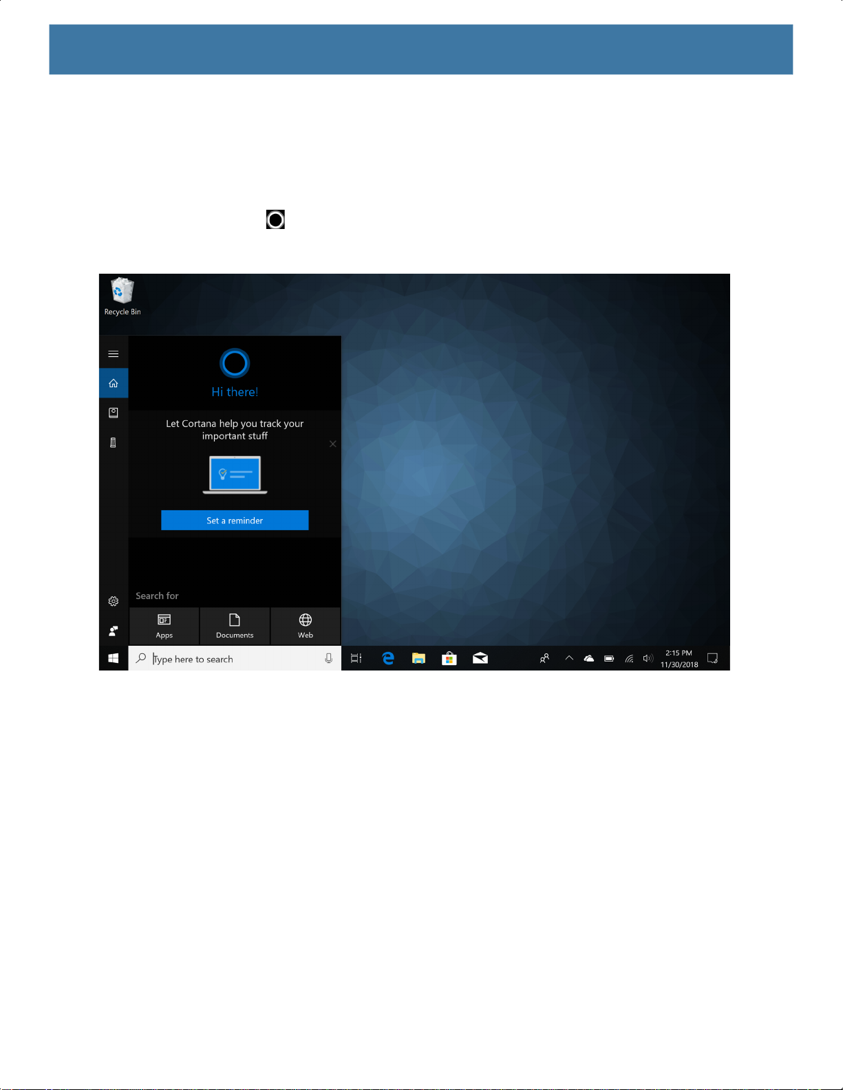
To check the software release information:
1. Touch the Cortana icon .
Figure 1 Software Release Information
About this Guide
2. In the Search text box, type
3. Touch Run Command. The User Account Control dialog box appears.
4. Touch Yes.
5. Navigate to HKEY_LOCAL_MACHINE > SOFTWARE > ReleaseInfo. The version appears in the Data
column.
regedit.
9
Page 11
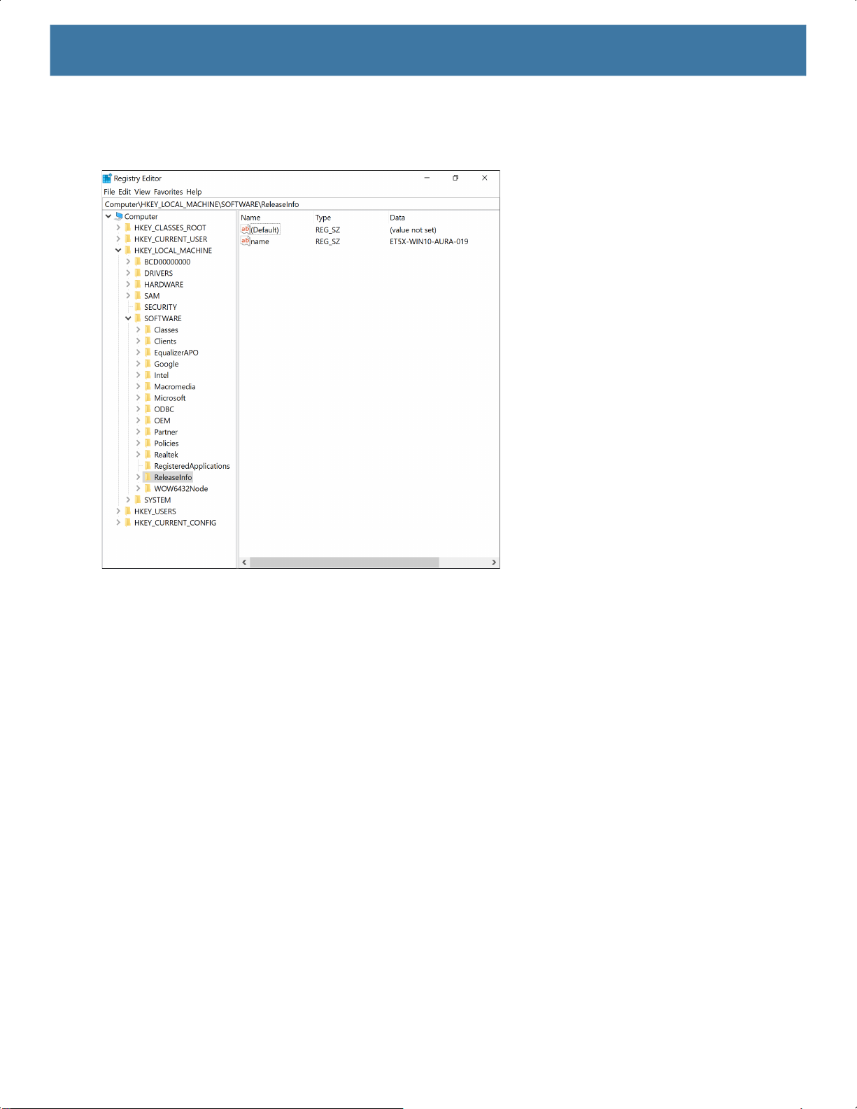
Figure 2 Regedit Window
About this Guide
Chapter Descriptions
Topics covered in this guide are as follows:
• Getting Started provides information on getting the tablet up and running for the first time.
• Accessories describes the accessories available for the tablet and how to use the accessories with the tablet.
• Software explains how to reset the tablet and perform system updates.
• Maintenance and Troubleshooting includes instructions on cleaning and storing the tablet, and provides
troubleshooting solutions for potential problems during tablet operation.
• Specifications includes the technical specifications for the tablet and accessories.
10
Page 12

Notational Conventions
The following conventions are used in this document:
• “Device” or “tablet” refers to the Zebra ET51/56 tablet
• Bold text is used to highlight the following:
• Dialog box, window and screen names
• Drop-down list and list box names
• Check box and radio button names
• Icons on a screen
• Key names on a keypad
• Button names on a screen.
• Bullets (•) indicate:
• Action items
• Lists of alternatives
• Lists of required steps that are not necessarily sequential.
• Sequential lists (e.g., those that describe step-by-step procedures) appear as numbered lists.
About this Guide
Related Documents and Software
The following documents provide more information about the tablets:
• ET51/56 Quick Reference Guide, p/n MN-003332-xx
• ET51 Enterprise Tablet with Integrated Scanner Quick Reference Guide, p/n MN-003777-xx
• ET51/56 User Guide for Microsoft Windows 10 IoT Enterprise, p/n MN-003446-xx
For the latest version of this guide and all guides, go to: http://www.zebra.com/support
Service Information
If you have a problem with your equipment, contact Zebra Global Customer Support for your region. Contact
information is available at: http://www.zebra.com/support
When contacting support, please have the following information available:
• Serial number of the unit
• Model number or product name
• Software type and version number. See Checking Operating System Version on page 60 for more information.
Zebra responds to calls by email, telephone or fax within the time limits set forth in support agreements.
If your problem cannot be solved by Zebra Customer Support, you may need to return your equipment for servicing
and will be given specific directions. Zebra is not responsible for any damages incurred during shipment if the
approved shipping container is not used. Shipping the units improperly can possibly void the warranty. Remove the
SD Card and SIM Card from the device before shipping.
.
.
If you purchased your Zebra business product from a Zebra business partner, contact that business partner for
support.
11
Page 13

Getting Started
Introduction
This chapter explains how to set up the device for the first time.
Unpacking
Carefully remove all protective material from around the device and save the shipping container for later
storage and shipping.
Verify that you received the following:
• Tablet with lithium polymer battery
• Quick Start Guide
• Additional hand strap screws (ET51 Enterprise Tablet with Integrated Scanner only)
• 1-slot cradle pads (ET51 Enterprise Tablet with Integrated Scanner only).
Inspect the equipment for damage. If you are missing any equipment or if you find any damaged equipment,
contact the Zebra Support Center immediately. See Service Information for contact information.
Getting Started
In order to start using the device for the first time:
• Install microSD card
• Install the nano SIM Card (ET56 only)
• Charge the battery
• Restart or reboot the device
12
Page 14
Getting Started
Installing a microSD Card or nano SIM Card
Remove the Battery
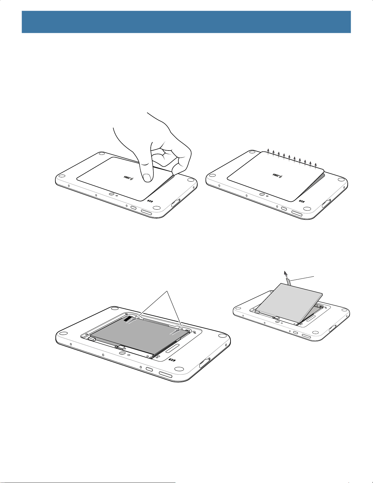
To remove the battery:
1. Lift the notched corner of the battery cover and carefully lift the battery cover off the device.
Figure 3 Lifting the Battery Cover
2. Carefully lift the battery cover off the device.
3. On the 8.4” version, push the two locking tabs up, then pull up on the tab to remove battery.
On the 10.1” version, push the two locking tabs up (1), then, using index fingers, lift the battery up (2).
Figure 4 Removing the Battery - 8.4”
Locking Tabs
Pull Tab
13
Page 15

Getting Started
Figure 5 Removing the Battery - 10.1”
Install the microSD card
To install a microSD card:
1. Insert the microSD card with contacts facing down; 8.4” version shown here.
Figure 6 Inserting microSD Card - 8.4”
14
Page 16

Getting Started
NANO
Figure 7 Inserting microSD Card - 10.1”
2. Push the micro SD card in and ensure that it locks into place.
Install the nano SIM card
To install the nano SIM card (ET56 only):
1. Insert the nano SIM card with contacts facing down.
Figure 8 Inserting the nano SIM Card - 8.4”
NANO
Figure 9 Inserting the nano SIM Card - 10.1”
2. Push the SIM card in and ensure that it locks into place.
15
Page 17
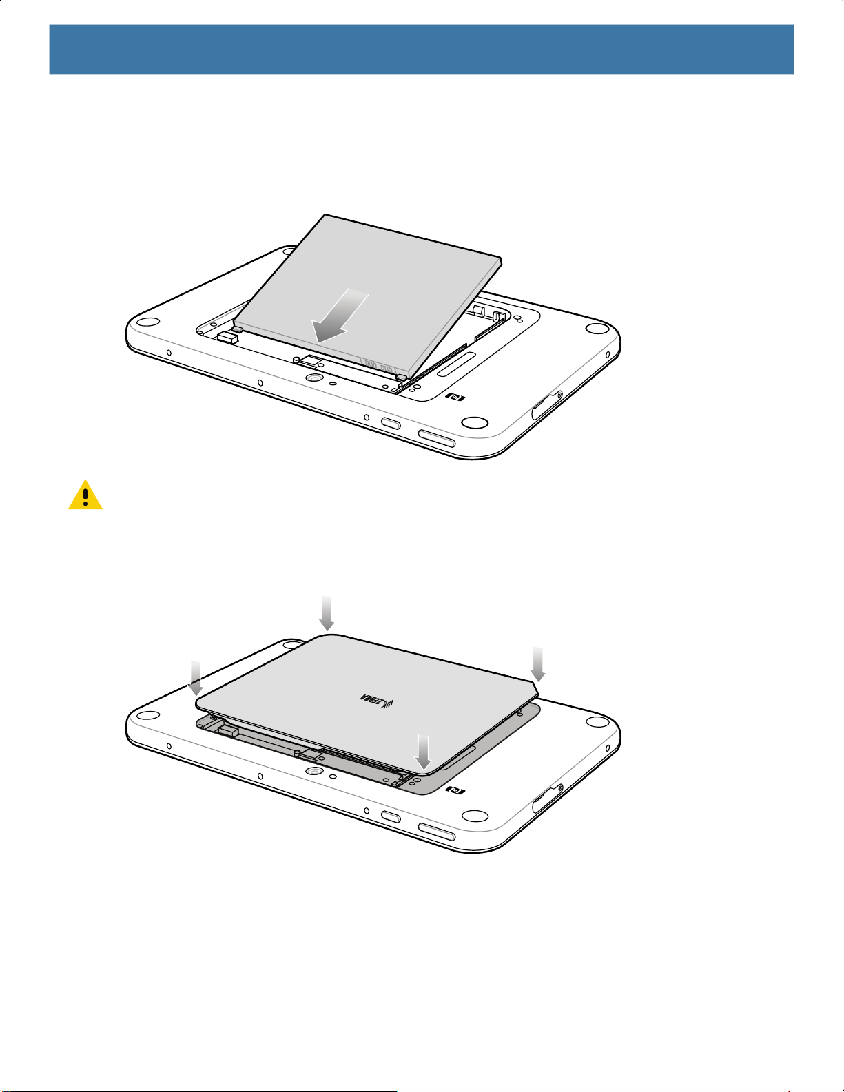
Replace the Battery
1. Replace the battery.
On the 10” version, ensure the two battery latches engage.
Figure 10 Inserting the Battery
Getting Started
CAUTION: Be aware of the orientation of the battery cover. Failure to replace the battery cover properly may damage the
battery cover.
2. Align the tabs on the underside of the cover with the slot around the battery well. Make sure that the notch
on the battery cover is at the bottom left cover of the device.
Figure 11 Aligning the Battery Cover
3. Carefully press down around the edge of the cover. Make sure that the cover is seated properly.
16
Page 18
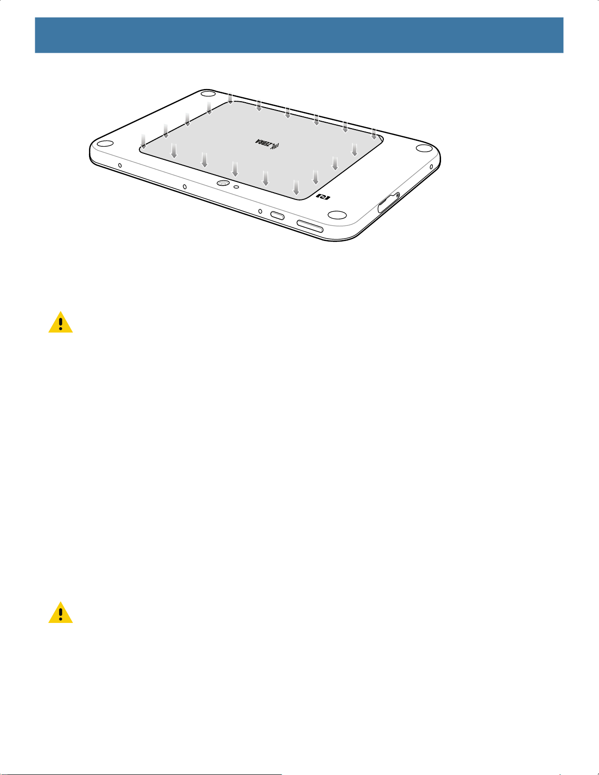
Figure 12 Pressing Down on the Battery Cover
4. Press Power button to turn on the device.
Replacing the SIM Card
CAUTION: To avoid damage to the SIM slot, do not pull the SIM card out of the SIM slot. Push the SIM card in to eject it.
Getting Started
To replace the SIM card:
1. Press and hold the Power button until the menu appears.
2. Touch Power off.
3. Lift the notched corner of the battery cover and carefully lift the battery cover off the device.
4. On the 8.4" version, push the two locking tabs up, then pull up on the tab to remove battery.
On the 10.1” version, push the two locking tabs up, then lift the battery up.
5. Push in the SIM card and release. The card ejects slightly.
6. Remove the SIM card from the card slot. The card should easily slide out. If not, the SIM card was not
ejected properly. Repeat step 5.
7. Replace the battery.
8. Press the battery down to ensure the two battery latches engage.
9. Replace the battery cover.
Replacing the microSD Card
CAUTION: To avoid damage to the microSD card slot, do not pull the microSD card out of the microSD Card slot. Push the
microSD card in to eject it.
To replace the microSD card:
1. Press and hold the Power button until the menu appears.
2. Touch Power off.
3. Lift the notched corner of the battery cover and carefully lift the battery cover off the device.
17
Page 19

4. On the 8.4" version, push the two locking tabs up, then pull up on the tab to remove battery.
On the 10.1” version, push the two locking tabs up, then lift the battery up.
5. Push in the SIM card and release. The card eject slightly.
6. Remove the microSD card from the card slot. The card should easily slide out. If not, the microSD card was
not ejected correctly. Repeat step 5.
7. Replace the microSD card.
8. Insert the replacement microSD card with contacts facing down.
9. Push the microSD card in and ensure that it locks into place.
10.Replace the battery.
11.Press the battery down to ensure the two battery latches engage.
12.Replace the battery cover.
Charging the Battery
NOTE: For best charging experience, Zebra recommends using one of the charging cradles or the Rugged
Charge Connector with power supply PWR-BGA-12V50W0WW. The tablets also supports charging using the
USB-C port. The Zebra PWR-WUA5V12W0xx power supply and USB-C cable (CBL-TC2X-USBC-01) can be
used but charge times will be longer and the tablet should not be subjected to heavy workloads while charging.
Getting Started
Use one of the cradles to charge the main battery installed in the device. See the chapter Accessories for
charging accessories. See the ET51/56 User Guide for information about battery management.
Alternately charge the device using a power supply and USB-C cable. Plug the USB-C connector into the
USB-C port.
The 8.4” tablet main battery charges from fully depleted to 90% in approximately 2 hours and from fully
depleted to 100% in approximately 3 hours.
The 10” main battery charges from fully depleted to 90% in approximately 3 hours and from fully depleted to
100% in approximately 5 hours.
NOTE: The Charging indicator only illuminates when the tablet is connected to AC power.
The Charging Indicator LED on the tablet indicates charging status as follows:
• OFF - device is not connected to charger.
• ORANGE - device is charging.
• GREEN - device is connected and fully charged.
• RED - charge error.
Restarting the Device
If the device is running slow or some applications are not functioning properly, restart the device:
1. Touch Start .
2. Touch Power > Update and restart.
3. If software updates are pending, these install and then the device restarts.
18
Page 20

Performing a Cold Boot
If the device does not respond to any input, perform a cold boot:
1. Press and hold the power button for at least 10 seconds. The device shuts down.
2. Press the Power button again to turn on the device.
Getting Started
19
Page 21

Accessories
Introduction
The device accessories provide a variety of product support capabilities.
Table 2 Device Accessories
Accessory Part Number Description
Cradles
Charge Only Cradle CRD-ET5X-1SCG2 Charges the main battery and optional Power
Communication and
Charging Cradle
Rugged Communication
and Charging Cradle
4-Slot Charge Only
Cradle
Chargers
Power Supply PWR-BGA12V50W0WW Provides power to the Charge Only Cradle,
Power Supply
CRD-ET5X-1SCOM1 Charges the main battery and optional Power
CRD-ET5X-1SCOM2R Charges the main battery and optional Power
CRD-ET5X-SE4CO2-01 Charges up to four main batteries and optional
PWR-BGA12V108W0WW
Pack installed in the Expansion Back. Requires
power supply PWR-BGA12V50W0WW, DC line
cord CBL-DC-388A1-01 and country-specific AC
line cord.
Pack installed in the Expansion Back. Requires
power supply PWR-BGA12V50W0WW, DC line
cord CBL-DC-388A1-01, and country-specific AC
line cord.
Pack installed in the Expansion Back. Supports
rugged frame and rugged IO Adapter. Requires
power supply PWR-BGA12V50W0WW, DC line
cord CBL-DC-388A1-01, and country-specific AC
line cord.
Power Pack installed in the Expansion Back and
up to four Power Packs in the optional 4-Slot
Battery Charger. Requires power supply
PWR-BGA12V108W0WW, DC line cord
CBL-DC-382A1-01, and country-specific AC line
cord.
Communication and Charging Cradles, Rugged
Charge Connector, and 4-Slot Battery Charger for
Optional Battery Power Pack.
Provides power to the 4-Slot Charge Only Cradle.
20
Page 22

Accessories
Table 2 Device Accessories (Continued)
Accessory Part Number Description
Power Supply PWR-WUA5V12W0xx
Where xx:
AR = Argentina
AU = Australia
BR = Brazil
CN = China
EU = European Union
Countries
GB = Great Britain
IN = India
KR = Korea
US = United States
4-Slot Battery Charger SAC-ET5X-4PPK1-01 Chargers up to four Power Packs. Requires power
Rugged Charge
Connector
Miscellaneous
Replacement 8.4"
Internal Battery
Replacement 10.1"
Internal Battery
Replacement 8.4"
Battery Cover
Replacement 10.1"
Battery Cover
8.4” Rugged Frame with
IO Adapter
10.1” Rugged Frame with
IO Adapter
Replacement Rugged IO
Connector
8.4" SE4750 Expansion
Back
8.4" SE4710 Expansion
Back
CHG-ET5X-CBL2-01 Charges the main battery and optional Power
BTRY-ET5X-8IN3-01 Replacement battery for 8.4" device.
BTRY-ET5X-10IN3-01 Replacement battery for 10.1" device.
KT-ET5X-8BTDR2-01 Replacement battery cover for 8.4" device.
KT-ET5X-10BTDR2-01 Replacement battery cover for 10.1" device.
SG-ET5X-8RCSE2-02 Add extra protection for the 8.4" device and IO
SG-ET5X-10RCSE2-01 Add extra protection for the 10.1" device and IO
SG-ET5X-RGIO2-01 Replacement rugged IO connector for the Rugged
ZBK-ET5X-8SCN5-01 Provides data capture using the SE4750 scan
ZBK-ET5X-8SCN1-01 Provides data capture using the SE4710 scan
Provides power to the tablet using USB-C cable
CBL-TC2X-USBC-01.
supply
CBL-DC-388A1-01, and country-specific AC line
cord.
Pack installed in the Expansion Back. Requires
power supply PWR-BGA12V50W0WW, DC Line
Cord CBL-DC-388A1-01 and country-specific AC
line cord.
Adapter for connection to the Rugged
Communication and Charging Cradle.
Adapter for connection to the Rugged
Communication and Charging Cradle.
Frames.
engine, rotating hand strap and slot for optional
Power Pack.
engine, rotating hand strap and slot for optional
Power Pack.
PWR-BGA12V50W0WW, DC Line cord
21
Page 23

Accessories
Table 2 Device Accessories (Continued)
Accessory Part Number Description
8.4" Expansion Back ZBK-ET5X-8RH1-01 Provides rotating hand strap and slot for optional
Power Pack.
10.1" SE4750 Expansion
Back
10.1" SE4710 Expansion
Back
10.1" Expansion Back ZBK-ET5X-10RH1-01 Provides rotating hand strap and slot for optional
Power Pack
Replacement Expansion
Back Hand Strap
Passive Stylus SG-TC7X-STYLUS-03 Provides easy writing, drawing, and navigation and
Coiled Stylus Tether SG-ET5X-SLTETR-01 Secures a stylus to the hand strap.
8.4" Operations Case SG-ET5X-8HLST-01 Provides carrying solution for 8.4" device.
10.1" Operations Case SG-ET5X-10HLST-01 Provides carrying solution for 10.1" device.
Universal Shoulder Strap 58-40000-007R Use with the Operations Case and D-clips to carry
Breakaway Shoulder
Strap
ZBK-ET5X-10SCN5-01 Provides data capture using the SE4750 scan
engine, rotating hand strap and slot for optional
Power Pack.
ZBK-ET5X-10SCN1-01 Provides data capture using the SE4710 scan
engine, rotating hand strap and slot for optional
Power Pack.
Power Pack.
BTRY-ET5X-PRPK2-01
SG-ET5X-RHTP1-01 Replacement hands strap for Expansion Backs.
SG-ET5X-SHDRSTP-01 Use with the Operations Case and D-clips to carry
Provides additional power for charging the device
battery using an Expansion Back.
accuracy with the thin tip and hovering capabilities.
device on shoulder.
device on shoulder. Contains safety feature by the
clips that breaks when pulled.
22
Page 24

Charge Only Cradle
CAUTION: Ensure that you follow the guidelines for battery safety described in Battery Safety Guidelines on page 62.
NOTE: The Charge Only Cradle (CRD-ET5X-1SCG2) comes with two inserts; tall insert and short insert. Install the tall insert
when using a device without a Rugged Frame or Expansion Back. Install the short insert when using with an Expansion Back
and without a Rugged Frame.
This section describes how to use a Charge Only Cradle with the device.
The Charge Only Cradle:
• Provides power for operating the device.
• Charges the device’s battery
• Supports the ET51 Enterprise Tablet with Integrated Scanner.
Power Setup
Figure 13 Charge Only Cradle Setup
a
Accessories
and optional Power Pack installed in an Expansion Back
.
Installing the Short Insert
Install the tall insert when using a device without a Rugged Frame or Expansion Back. Install the short insert
when using an device with an Expansion Back and without a Rugged Frame.
1. Align the insert over the pins.
23
Page 25

Figure 14 Align Insert with Cradle
2. Press the insert down until it seats flush in the cradle.
Installing the Tall Insert
Install the tall insert when using a device without a Rugged Frame or Expansion Back.
Accessories
1. Peel the tape off the back of the insert.
2. Align the tall insert over the pins.
Figure 15 Align Insert with Cradle
3. Press the insert down until it seats flush in the cradle.
24
Page 26

4. Press the tabs against the cradle to secure the insert to the cradle.
Charging the Device
Accessories
To charge the device in the Charge Only Cradle:
1. Align the device with the alignment pins on the cradle.
2. Insert the device into the cradle.
NOTE: Ensure the device is flat on the cradle and all charging contacts are touching the charging base.
Figure 16 Insert Device into Charge Only Cradle
3. The device Charging LED indicates charging.
25
Page 27

Accessories
4. To remove the device from the Charge Only Cradle, hold the cradle down with one hand and lift the device.
Figure 17 Remove device from Charge Only Cradle
Charge batteries in ambient temperatures from 0°C to +60°C (32°F to 140°F) as reported by the battery.
Charging is intelligently controlled by the charger. To accomplish this, for small periods of time, the charger
alternately enables and disables battery charging to keep the battery at acceptable temperatures.
The 8.4” main battery charges from fully depleted to 90% in approximately 2 hours and from fully depleted to
100% in approximately 3 hours.
The 10.1” main battery charges from fully depleted to 90% in approximately 3 hours and from fully depleted to
100% in approximately 5 hours.
NOTE: The Charging indicator only illuminates when the device is connected to AC power.
Table 3 Charging Indicator
LED Indication
Off Device is not in cradle; not seated properly; or cradle is not powered.
Orange Device is charging.
Green Charging complete.
Red Error in charging; check placement of the device.
26
Page 28

Accessories
Communication and Charging Cradle
CAUTION: Ensure that you follow the guidelines for battery safety described in Battery Safety Guidelines on page 62.
NOTE: The Communication and Charging Cradle (CRD-ET5X-1SCOM2) comes with two inserts; tall insert and short insert.
Install the tall insert when using without a Rugged Frame or Expansion Back. Install the short insert when using with an Expansion Back and without a Rugged Frame.
The Communications and Charging Cradle does not support the ET51 Enterprise Tablet with Integrated Scanner.
This section describes how to use a Communication and Charging Cradle with the device.
The Communication and Charging cradle:
• Provides power for operating the device.
• Provides ports for connecting USB devices, video output and connection to a LAN.
• Charges the device’s battery
Power Setup
and optional Power Pack installed in an Expansion Back
.
Figure 18 Communication and Charging Cradle - Setup
Installing the Insert
Install the tall insert when using a device without a Rugged Frame or Expansion Back. Install the short insert
when using a device with an Expansion Back and without a Rugged Frame.
1. Align the insert over the pins.
27
Page 29

Figure 19 Align Insert with Cradle
2. Press the insert down until it seats flush in the cradle.
Charging the Device
To charge the device in the Communication and Charging Cradle:
Accessories
1. Open the bottom access door and hold it to the back of the device.
2. Align the device with the alignment pins on the cradle.
3. Insert the device into the cradle. Note that the Communication and Charging Cradles contains a locking
mechanism that locks the device to the cradle.
NOTE: Ensure the device is flat on the cradle and all charging contacts are touching the charging base.
Figure 20 Insert device into Communication and Charging Cradle
4. The device Charging LED indicates charging.
28
Page 30

Accessories
5. To remove the device from the Communication and Charging Cradle, press the release button on the right
side of the cradle and lift the device. Use thumb to hold down the cradle.
Figure 21 Remove ET5X from Communication and Charging Cradles
Charge batteries in ambient temperatures from 0°C to +60°C (32°F to 140°F) as reported by the battery.
Charging is intelligently controlled by the charger. To accomplish this, for small periods of time, the charger
alternately enables and disables battery charging to keep the battery at acceptable temperatures.
The 8.4” main battery charges from fully depleted to 90% in approximately 2 hours and from fully depleted to
100% in approximately 3 hours.
The 10.1” main battery charges from fully depleted to 90% in approximately 3 hours and from fully depleted to
100% in approximately 5 hours.
NOTE: The Charging indicator only illuminates when the device is connected to AC power.
29
Page 31

Accessories
Rugged Communication and Charging Cradle
CAUTION: Ensure that you follow the guidelines for battery safety described in Battery Safety Guidelines on page 62.
This section describes how to use a Rugged Communication and Charging Cradle with the device.
The Rugged Communication and Charging cradle:
• Provides power for operating the device.
• Provides ports for connecting USB devices, video output and connection to a LAN.
• Charges the device’s battery
• Supports the ET51 Enterprise Tablet with Integrated Scanner.
Power Setup
Figure 22 Rugged Communication and Charging Cradle - Setup
and optional Power Pack installed in an Expansion Back
.
Using with the ET51 Enterprise Tablet with Integrated Scanner
Before placing the ET51 Enterprise Tablet with Integrated Scanner into the cradle, install the two rubber pads
onto the cradle.
30
Page 32

Figure 23 Install Rubber Pads
Charging the Device
To charge the device using the Rugged Communication and Charging Cradle:
Accessories
1. Align the device with the alignment pins on the cradle.
2. Insert the device into the cradle. Note that the Rugged Communication and Charging Cradles contains a
locking mechanism that locks the device to the cradle.
NOTE: Ensure the device is flat on the cradle and all charging contacts are touching the charging base.
Charge batteries in ambient temperatures from 0°C to +60°C (32°F to 140°F) as reported by the battery.
Charging is intelligently controlled by the charger. To accomplish this, for small periods of time, the charger
alternately enables and disables battery charging to keep the battery at acceptable temperatures.
The 8.4” main battery charges from fully depleted to 90% in approximately 2 hours and from fully depleted to
100% in approximately 3 hours.
The 10.1” main battery charges from fully depleted to 90% in approximately 3 hours and from fully depleted to
100% in approximately 5 hours.
NOTE: The Charging indicator only illuminates when the device is connected to AC power.
31
Page 33

4-Slot Charge Only Cradle
CAUTION: Ensure that you follow the guidelines for battery safety described in Battery Safety Guidelines on page 62.
• Provides 5 VDC power for operating the device.
• Simultaneously charges up to four devices and up to four Power Packs using the optional Battery Charger
Adapter.
Power Setup
Figure 24 Power Setup with Optional Charger
PWR-BGA12V108W0WW
Accessories
PWR-BGA12V50W0WW
Insert Installation
Install inserts into slots for devices without Rugged Frame.
32
Page 34

Figure 25 Install Insert in Slot
Insert Device into Slot
Accessories
Device without Rugged Frame
1. Install insert into slot.
2. Align the two alignment holes on the bottom of the device with the two alignment pins in the slot.
Figure 26 Insert ET5X without Rugged Frame into Slot
3. Place the device down into the slot with display facing away from Battery Charger.
Device with Rugged Frame
1. If applicable, remove insert from slot.
33
Page 35

Accessories
2. Slide device over slot until it touches the guide.
Figure 27 Insert device with Rugged Frame into Slot
3. Place the device down into the slot with display facing away from Battery Charger.
ET51 Enterprise Tablet with Integrated Scanner
1. If applicable, remove insert from slot.
2. Slide device over slot until it touches the guide.
3. Place the device down into the slot with display facing away from Battery Charger.
34
Page 36

Charging the Battery
Charge batteries in ambient temperatures from 0°C to +60°C (32°F to 140°F) as reported by the battery.
Charging is intelligently controlled by the charger. To accomplish this, for small periods of time, the charger
alternately enables and disables battery charging to keep the battery at acceptable temperatures.
The 8.4” main battery charges from fully depleted to 90% in approximately 2 hours and from fully depleted to
100% in approximately 3 hours.
The 10.1” main battery charges from fully depleted to 90% in approximately 3 hours and from fully depleted to
100% in approximately 5 hours.
NOTE: The Charging indicator only illuminates when the device is connected to AC power.
Accessories
35
Page 37

Accessories
Using the 4-Slot Battery Charger
CAUTION: Ensure that you follow the guidelines for battery safety described in Battery Safety Guidelines on page 62.
Use the 4-Slot Battery Charger to charge up to four Power Packs.
Power Setup
Figure 28 4-Slot Battery Charger Setup
Charging the Power Pack
Charge Power Packs in ambient temperatures from 0°C to +60°C (32°F to 140°F) as reported by the Power
Pack. Charging is intelligently controlled by the charger. To accomplish this, for small periods of time, the
charger alternately enables and disables Power Pack charging to keep the battery at acceptable temperatures.
The Power Pack charge LED shows the status of the battery charging. The Power Pack charges in less than
three hours. When charging, the Charge LEDs indicate the charge level.
Figure 29 Power Pack Charge LEDs
Charge Level Indicators
36
Page 38

Accessories
Table 4 Power Pack Charge Status Indicators
Power Pack
Indicators
Description
Power not applied to Power Pack.
Charge level is between 0% and 20%.
Charge level is between 20% and 40%.
Change level is between 40% and 60%.
Charge level is between 60% and 80%.
Charge level is between 80% and 100%.
Fully charged.
Charging error.
Solid Green LED
Blinking Green LED
Blinking Red LED
37
Page 39

Rugged Frame
NOTE: The Rugged Frame does not support the ET51 Enterprise Tablet with Integrated Scanner.
The Rugged Frame (8.4” and 10.1”) adds additional protection to the device. Use the Rugged I/O Adapter
when docking the device into the Rugged Communications and Charging Cradle.
1. Open the access cover.
Figure 30 Open Access Door
Accessories
2. If installing the Rugged IO Adapter, pull the access cover away from the device until it separates from the
device.
Figure 31 Remove Access Door
3. Insert the Rugged IO Adapter onto the device.
38
Page 40

Accessories
Figure 32 Insert Rugged IO Adapter
4. Remove the Rugged Frame and screws from box.
5. Separate the top and bottom sections of the Rugged Frame.
6. Place the bottom section on a flat surface.
Figure 33 Protective Boot Assembly
Interface Connector
Rugged IO Adapter
7. Place the device into the bottom section.
8. Align the top section over the bottom section.
9. Press the top section down onto the bottom section.
10.Using a T6 Torx screwdriver, secure the Rugged Frame together using the provided M1.6 Torx screws.
39
Page 41

Figure 34 Secure 8.4” Rugged Frame
Figure 35 Secure 10.1” Rugged Frame
Accessories
11.Torque the screws to 12 N-cm.
40
Page 42

Expansion Back
NOTE: The Expansion Back does not support the ET51 Enterprise Tablet with Integrated Scanner.
The Expansion Backs provide data capture and or Power Pack slot for the device.
Installation
To install an Expansion Back:
CAUTION: Remove power before installing the Expansion Back.
1. Power off the device.
2. Remove battery cover and store in safe place.
Figure 36 Remove Battery Cover
Accessories
3. On 8.4” version only, remove rubber gasket.
Figure 37 Remove Rubber Gasket
Rubber Gasket
41
Page 43

Accessories
Figure 38 Align Expansion Back with 8.4” Configuration
Power Pack
Slot Cover
Interface Connector
4. Align expansion back with device. Ensure that the power pack slot cover is aligned with the bottom of the
device and the interface connector on expansion back aligns with interface connector on device.
Figure 39 Align Expansion Back with 10.1” Configuration
Power Pack Slot
Cover
Interface Connector
42
Page 44

Figure 40 Secure Screws
Screws (4)
5. Using a T6 Torx screwdriver, secure expansion back to device using four screws. Torque to 14 n-cm.
Replacement Hand Strap
Accessories
To replace the hand strap:
1. If the Power Pack is installed, remove the Power Pack.
2. Rotate the disk so that the strap end without the eyelet is aligned with the Power Pack opening.
3. Open both ends of the hand strap.
Figure 41 Open Straps
4. Pull the strap end without the eyelet through the slot on the Expansion Back.
43
Page 45

Figure 42 Remove Strap
Accessories
5. Rotate the disk 180°.
6. Slide the pad off the hand strap.
7. Pull the eyelet end through the slot on the Expansion Back.
Figure 43 Pull Eyelet End
8. Remove pad from new replacement hand strap.
9. Rotate the disk so that one of the slots is aligned with the Power Pack opening.
44
Page 46

Accessories
10.Feed the new hand strap through the slot at the Power Pack opening.
Figure 44 Feed New Strap
Eyelet
Power Pack
Opening
Hook
Material
Disk Slot
Hook
Material
Disk Slot
Hand Strap Disk
11.Slide pad onto hand strap with the stylus holder facing up.
12.Fold the eyelet end of the strap up and press hook and loop material together.
Figure 45 Secure Eyelet End
Pad
Stylus
Holder
13.Rotate disk 180° so that the empty slot is aligned with the Power Pack opening.
14.Feed strap through the slot.
45
Page 47

Accessories
Figure 46 Feed Strap
15.Fold the end of the strap up and press hook and loop material together.
Figure 47 Secure Strap
Attaching the Stylus to the Expansion Back
The Expansion Backs provide a holder for the stylus. To install the stylus onto the Expansion Back:
Figure 48 Passive Stylus
1. Insert the loop of the tether through the eyelet on the hand strap of the Expansion Back.
2. Feed the stylus through the loop.
46
Page 48

Figure 49 Feed Stylus through Loop
3. Pull the stylus all the way through the loop.
4. Slide the stylus into the holder for storing the stylus.
Removal
To remove an Expansion Back:
CAUTION: Remove power before removing the Expansion Back.
Accessories
1. Power off the device.
2. Using a T6 Torx screwdriver, remove four screws securing expansion back to device.
Figure 50 Remove Screws
Screws (4)
3. Lift Expansion Back off device.
47
Page 49

Accessories
Figure 51 Lift Expansion Back
4. On 8.4” version only, replace rubber gasket removed during installation.
Figure 52 Rubber Gasket Replacement
Rubber Gasket
5. Replace battery cover.
Figure 53 Align Battery Cover
6. Carefully press down around the edge of the cover. Make sure that the cover is seated properly.
48
Page 50

Accessories
Figure 54 Press Down on Battery Cover
7. Press the Power button to turn on the device.
49
Page 51

Accessories
ET51 with Integrated Scanner Hand Strap
The ET51 Enterprise Tablet with Integrated Scanner comes with additional screws for securing the hand strap
to the device.
Removing the Hand Strap
To remove the hand strap:
1. Push the hand strap stud through the hole of the lower hand strap.
2. Pull the lower hand strap from the upper hand strap.
3. Remove the two screws and two washers securing the upper and lower hand strap to the device.
Installing the Hand Strap on the Back of the Device
To install the hand strap on the back of the device:
1. Align the upper and lower hand strap mounting holes with the screw holes on the device.
50
Page 52

Accessories
Washer
M2.5x11 Screw
Washer
2. Using a T6 Torx screwdriver, secure the upper and lower hand strap to the device using the one M2x6
screw, one M2.5x11 screw, and two washers.
3. Torque the screws to 20 N-cm (1.77 lb in).
M2x6 Screw
4. Feed the lower half of the hand strap through the upper half.
5. Position the hand strap for the right fit.
6. Align the stud with a hole in the lower half.
7. Press the lower hand strap down until the stud comes through the hole.
51
Page 53

Accessories
Installing the Hand Strap on the Side of the Device
To install the hand strap on the side of the device:
1. Align the upper and lower hand strap mounting holes with the screw holes on the device.
Washer
M2.5x11 Screw
2. Using a T6 Torx screwdriver, secure the upper and lower hand strap to the device using the two M2.5x11
screws, and two washers.
3. Torque the screws to 20 N-cm (1.77 lb in).
4. Feed the lower half of the hand strap through the upper half.
52
Page 54

Accessories
5. Position the hand strap for the right fit.
6. Align the stud with a hole in the lower half.
7. Press the lower hand strap down until the stud comes through the hole.
53
Page 55

Software
Introduction
This chapter provides instructions on how to reset and update the tablet.
Factory Reset
Restores Windows to original factory settings. To reset the device:
1. Place the device in a Charging or Communications and Charging cradle.
2. Touch Settings > Update and security > Recovery.
3. Under Reset this PC, touch Get started.
Figure 1 Reset Option Dialog Box
4. Touch Keep my files to remove all apps and settings but keep all personal files or Remove everything to
remove all personal files, apps, and settings.
CAUTION: Removing everything erases all data, including your account configuration, applications, music, pictures and files.
Make sure that you back up all the required data before you proceed.
5. Touch Next until the reset process begins. The process can take an hour or longer.
6. When the reset is complete the Windows setup process begins. See Initial Windows Setup for information.
54
Page 56

Software
Operating System and Firmware Updates
System Update packages contain either partial or complete updates for the firmware and operating system.
Zebra distributes the System Update packages on the Zebra Support & Downloads web site.
1. Navigate to the Zebra Support & Downloads web site, http://www.zebra.com/support.
2. Download the appropriate System Update package to a host computer and unzip the file.
Creating an Installation USB Flash Drive
Follow these steps to create a bootable installation on a USB flash drive.
1. Insert an 8 GB or larger USB flashflash drive into a host computer.
2. From Windows Explorer right click on the USB flash drive and select Format.
Figure 2 Format Dialog Box
3. In the File system drop down, select FAT32.
CAUTION: Only FAT32 format is recognized by the system BIOS.
4. In the Volume label text box, enter BOOTME.
5. Click Start. A warning appears; click OK to proceed.
6. Click OK when the format complete and confirmation dialogs appear.
7. Using Windows Explorer, copy the System Update package files you downloaded onto the flash drive.
8. Ensure that all the files copied successfully and then safely unmount the USB drive.
55
Page 57

Performing the System Updates
Setup Using a Communication Dock
The following is required:
• USB keyboard
• Communication Dock with power supply.
• Bootable installation USB flashflash drive (the one you created in the previous step).
1. Connect power to the Communication Dock.
2. Insert the tablet into the Communication Dock.
3. Plug the USB keyboard connector into a USB port on the back of the dock.
4. Plug the bootable USB flash drive into the tablet USB port.
Setup Using a USB Hub
The following is required:
Software
• USB keyboard
• USB-C Hub with external power supply
• USB cable/charger
• Bootable installation USB flash drive (the one you created in the previous step)
56
Page 58

Figure 3 Setup Using USB Hub
Software
The picture illustrates the following:
1. Device.
2. USB-C hub with external power source.
3. USB-C charger connected to USB-C port.
4. USB-C hub connected to device USB-C port.
5. USB keyboard connected to USB-C hub.
6. Bootable installation USB stick connected to USB-C hub.
Initiating the Update
To initiate the update:
1. Re-boot the device; when the Zebra logo displays, press the ESC key repeatedly until the boot screen
appears.
2. On the keyboard, press the right arrow key to highlight Boot Manager.
57
Page 59

3. Press ENTER. The following displays:
• Windows Boot Manager
• EFI USB Device.
NOTE: If Boot Manager does not display EFI USB Device (USB flash drive type), confirm that the USB is formatted as FAT32
and that
4. Using the keyboard, use the arrow keys to highlight EFI USB Device then press ENTER. The tablet boots
5. When complete, the device boots and the Windows setup process initiates. See Initial Windows Setup.
6. After Windows setup is complete, in the taskbar, touch , then touch , then touch Eject (drive name).
7. After the message Safe To Remove Hardware message appears, remove the flash drive from the tablet.
bootmgr.efi file is visible on the USB drive. Re-seat the USB drive in the USB port and try again.
to WinPE and installs operating system and BIOS updates. Installation takes approximately 9 minutes.
Initial Windows Setup
After performing a factory reset or updating the tablet firmware or operating system, the Windows setup
process begins.
Software
The Cortana welcome screen appears and then a series of windows prompt you for information regarding your
preferences including Keyboard Layout, Network Setup, Account Name, Security, and Privacy.
Next, a short configuration process occurs after which the Windows home screen displays.
Figure 4 Windows Home Screen
Any apps that you installed from the Windows Store prior to reset, are automatically reinstalled using your
mobile broadband or Wi-Fi internet connection when connected; apps installed from other sources are not.
After the process is complete a list of apps removed during reset is created on the desktop.
58
Page 60

Checking Versions
You may check the versions for:
• EC FW (firmware)
• BIOS
• Operating system.
Check EC FW Version
1. Setup tablet with USB hub or cradle. See Setup Using a Communication Dock and Setup Using a USB
Hub.
2. Reboot the tablet and when the logo appears, press ESC key on keyboard.
3. Use the keyboard arrow keys to select Setup Utility.
4. Press Enter key. The BIOS screen appears.
Figure 5 BIOS Screen
Software
5. Check EC FW field to view the version number:
e.g. EC FW = 1_8.
6. Press ESC key to exit the BIOS screen.
7. Use the arrow keys to select Continue.
59
Page 61

8. Press Enter to reboot the tablet.
Check BIOS Version
To check the current version of the BIOS:
1. In the Cortana search field, type cmd, then touch Command Prompt Desktop App to open.
Software
2. In the Command window, type
3. Press Enter key. The System Information window appears. The BIOS version displays in the BIOS
Version/Date field.
Figure 6 System Information Window
msinfo32.
Checking Operating System Version
To check the current operating system version:
1. In the Cortana search field, type
2. In the Command window, type
on the screen.
cmd, then touch Command Prompt Desktop App to open.
reg query HKLM\Software\ReleaseInfo. The release information appears
60
Page 62

Software
Figure 7 Release Information
Zebra Barcode Scanning Resources
To obtain Zebra scanning resources such as applications, SDKs, drivers, and RFID software see the Zebra
Barcode Scanning Software web page:
http://www.zebra.com/us/en/products/software/scanning-systems.html
Application Installation
Install programs and apps from the Internet, or a local network. Make sure you trust the publisher of the app
and the website.
In your web browser, tap or click the link to the app. To install it now, tap Open or Run, and then follow the
instructions on your screen. To install the app later, tap Save or Save as to download it.
Windows Store
To obtain apps from the Windows Store, select the Store tile from the Start menu or taskbar.
.
61
Page 63

Maintenance and Troubleshooting
Introduction
This chapter includes instructions on cleaning and storing the tablet, battery maintenance and provides
troubleshooting solutions for potential problems during tablet operations.
Maintaining the Device
For trouble-free service, observe the following tips when using the device:
• To avoid scratching the screen, use the supplied stylus or plastic-tipped pens intended for use with a
touch-sensitive screen. Never use an actual pen or pencil or other sharp object on the surface of the device
screen.
• The touch-sensitive screen of the device is glass. Do not drop the device or subject it to strong impact.
• Protect the device from temperature extremes. Do not leave it on the dashboard of a car on a hot day, and
keep it away from heat sources.
• Do not store the device in any location that is dusty, damp, or wet.
• Use a soft lens cloth to clean the device. If the surface of the device screen becomes soiled, clean it with a
soft cloth moistened with an approved cleanser. For a list of approved cleansers, see Approved Cleanser
Active Ingredients.
• Periodically replace the rechargeable battery to ensure maximum battery life and product performance.
Battery life depends on individual usage patterns.
Battery Safety Guidelines
• The area in which the units are charged should be clear of debris and combustible materials or chemicals.
Particular care should be taken where the device is charged in a non commercial environment.
• Follow battery usage, storage, and charging guidelines found in this guide.
• Improper battery use may result in a fire, explosion, or other hazard.
• To charge the mobile device battery, the ambient battery and charger temperatures must be between
+32ºF and +104ºF (0ºC and +40ºC).
• Do not use incompatible batteries and chargers, including non-Zebra batteries and chargers. Use of an
incompatible battery or charger may present a risk of fire, explosion, leakage, or other hazard. If you have
any questions about the compatibility of a battery or a charger, contact the Global Customer Support
Center.
• For devices that utilize a USB port as a charging source, the device shall only be connected to products that
bear the USB-IF logo or have completed the USB-IF compliance program.
• Do not disassemble or open, crush, bend or deform, puncture, or shred the battery.
62
Page 64

• Severe impact from dropping any battery-operated device on a hard surface could cause the battery to
overheat.
• Do not short circuit a battery or allow metallic or conductive objects to contact the battery terminals.
• Do not modify or remanufacture, attempt to insert foreign objects into the battery, immerse or expose to water
or other liquids, or expose to fire, explosion, or other hazard.
• Do not leave or store the equipment in or near areas that might get very hot, such as in a parked vehicle or near
a radiator or other heat source. Do not place battery into a microwave oven or dryer.
• Battery usage by children should be supervised.
• Please follow local regulations to properly dispose of used re-chargeable batteries.
• Do not dispose of batteries in fire.
• In the event of a battery leak, do not allow the liquid to come in contact with the skin or eyes. If contact has been
made, wash the affected area with water for 15 minutes, and seek medical advice.
• If you suspect damage to your equipment or battery, contact Customer Support to arrange for inspection.
Cleaning Instructions
Maintenance and Troubleshooting
CAUTION: Always wear eye protection.
Read warning label on alcohol product before using.
If you have to use any other solution for medical reasons please contact the Global Customer Support Center for more information.
WARNING: Avoid exposing this product to contact with hot oil or other flammable liquids. If such exposure occurs, unplug the
device and clean the product immediately in accordance with these guidelines.
Approved Cleanser Active Ingredients
100% of the active ingredients in any cleaner must consist of one or some combination of the following: isopropyl
alcohol, bleach/sodium hypochlorite
IMPORTANT: Use pre-moistened wipes and do not allow liquid cleaner to pool.
1
When using sodium hypochlorite (bleach) based products, always follow the manufacturer’s recommended instructions: use
gloves during application and remove the residue afterwards with a damp alcohol cloth or a cotton swab to avoid prolonged skin
contact while handling the device.
Due to the powerful oxidizing nature of sodium hypochlorite, the metal surfaces on the device are prone to oxidation (corrosion)
when exposed to this chemical in the liquid form (including wipes). In the event that these
with metal on the device, prompt removal with an alcohol-dampened cloth or cotton swab after the cleaning step is critical.
1 (see important note below)
Harmful Ingredients
, or mild dish soap.
type of disinfectants come in contact
The following chemicals are known to damage the plastics on the device and should not come in contact with the
device: acetone; ketones; ethers; aromatic and chlorinated hydrocarbons; aqueous or alcoholic alkaline solutions;
ethanolamine; toluene; trichloroethylene; benzene; carbolic acid and TB-lysoform.
Many vinyl gloves contain phthalate additives, which are often not recommended for medical use and are known to
be harmful to the housing of the device.
If using the tablet in a healthcare environment, do not use PDI Sani-Hands/ PDI Super Sani Cloth Germicidal
Wipes to clean the device.
63
Page 65

Maintenance and Troubleshooting
Device Cleaning Instructions
Do not apply liquid directly to the device. Dampen a soft cloth or use pre-moistened wipes. Do not wrap the device
in the cloth or wipe, instead gently wipe the unit. Be careful not to let liquid pool around the display window or other
places. Before use, allow the unit to air dry.
NOTE: For thorough cleaning, it is recommended to first remove all accessory attachments, such as hand straps or cradle cups,
from the mobile device and to clean them separately.
Special Cleaning Notes
The device should not be handled while wearing vinyl gloves containing phthalates, or before hands are washed to
remove contaminant residue after gloves are removed.
If products containing any of the harmful ingredients listed above are used prior to handling the device, such as
hand sanitizer that contain ethanolamine, hands must be completely dry before handling the device to prevent
damage to the device.
IMPORTANT: If the battery connectors are exposed to cleaning agents, thoroughly wipe off as much of the chemical as possible
and clean with an alcohol wipe. It is also recommended to install the battery in the terminal prior to cleaning and disinfecting the
device to help minimize buildup on the connectors.
When using cleaning/disinfectant agents on the device, it is important to follow the directions prescribed by the
cleaning/disinfectant agent manufacturer.
Cleaning Materials Required
• Alcohol wipes
• Lens tissue
• Cotton-tipped applicators
• Isopropyl alcohol
• Can of compressed air with a tube.
Cleaning Frequency
The cleaning frequency is at the customer’s discretion due to the varied environments in which the mobile devices
are used and may be cleaned as frequently as required. When dirt is visible, it is recommended to clean the mobile
device to avoid build up of particles which make the device more difficult to clean later on.
Cleaning Battery Connectors
To clean the battery connectors:
1. Remove the main battery from the mobile computer.
2. Dip the cotton portion of the cotton-tipped applicator in isopropyl alcohol.
3. To remove any grease or dirt, rub the cotton portion of the cotton-tipped applicator back-and-forth across the
connectors on the battery and terminal sides. Do not leave any cotton residue on the connectors.
64
Page 66

Maintenance and Troubleshooting
4. Repeat at least three times.
5. Use a dry cotton-tipped applicator and repeat steps 3 and 4. Do not leave any cotton residue on the connectors.
6. Inspect the area for any grease or dirt and repeat the cleaning process if necessary.
CAUTION: After cleaning the battery connectors with bleach-based chemicals, follow the Battery Connector Cleaning instructions
to remove bleach from the connectors.
Cleaning Cradle Connectors
To clean the connectors on a cradle:
1. Remove the DC power cable from the cradle.
2. Dip the cotton portion of the cotton-tipped applicator in isopropyl alcohol.
3. Rub the cotton portion of the cotton-tipped applicator along the pins of the connector. Slowly move the
applicator back-and-forth from one side of the connector to the other. Do not leave any cotton residue on the
connector.
4. All sides of the connector should also be rubbed with the cotton-tipped applicator.
5. Remove any lint left by the cotton-tipped applicator.
6. If grease and other dirt can be found on other areas of the cradle, use a lint-free cloth and alcohol to remove.
7. Allow at least 10 to 30 minutes (depending on ambient temperature and humidity) for the alcohol to air dry
before applying power to cradle.
If the temperature is low and humidity is high, longer drying time is required. Warm temperature and low
humidity requires less drying time.
CAUTION: After cleaning the cradle connectors with bleach-based chemicals, follow the Cleaning Cradle Connectors instructions
to remove bleach from the connectors.
Troubleshooting
Table 1 Troubleshooting the tablet
Problem Cause Solution
Tablet does not turn
on.
Battery not charged. Charge the battery in the tablet.
Battery not installed
properly.
System crash. If the tablet does not turn on, perform a cold boot. See
Ensure battery is installed properly.
Performing a Cold Boot on page 19.
65
Page 67

Maintenance and Troubleshooting
Table 1 Troubleshooting the tablet (Continued)
Problem Cause Solution
Battery did not charge. Battery failed. Replace battery. If the tablet still does not operate, try a
cold boot. See Performing a Cold Boot on page 19.
Tablet removed from
cradle before
charging completed.
Ambient temperature
of the cradle is too
warm or too cold.
Unable to connect to
the wireless network.
The multi-touch screen
responds slowly or
improperly.
Tablet turns itself off. Tablet is inactive. The tablet turns off after a period of inactivity. If the tablet is
After selecting a link in
a full-screen app
(Tablet mode), a dialog
box or app does not
display.
SIM card is invalid. Ensure that the micro SIM card is valid and workable if
Not within range of
network.
device is in airplane
mode.
Finger or screen is
wet.
Battery is depleted. Place the tablet in the cradle to re-charge the battery.
The tablet’s battery
is low and it powers
down to protect
memory content.
The dialog box or
app is hidden behind
the full-screen app.
Insert the tablet into the cradle and begin charging. The
battery fully charges in approximately four hours.
The ambient temperature must be between 0 °C and 40 °C
(32 °F and 104 °F).
using a mobile network.
Move within the network’s service range and the signal
strength is good.
Ensure that device is not in Airplane mode.
Ensure that your hands are clean and dry when touching
the screen. Restart the tablet to try again.
running on battery power.
Place the tablet in a cradle to re-charge the battery.
Touch in the taskbar to view all running apps and select
the dialog box or app.
Tablet clock is not
synchronizing with
local time after
enabling the WAN
radio.
Windows Time
Services is not set
properly.
Open Control Panel > Administrative Tools > Services
> Windows Time. In the Startup Type drop-down list,
select Automatic. In the Services status section, touch
Start.
66
Page 68

Maintenance and Troubleshooting
Charge Only Cradle
Table 2 Troubleshooting the Charge only Cradle
Symptom Possible Cause Solution
Battery is not
charging.
Tablet was removed
from cradle or cradle
was unplugged from AC
power.
Battery is faulty. Verify that other batteries charge properly. If so, replace the faulty
The tablet is not fully
seated in the cradle.
Ambient temperature of
the cradle is too warm or
too cold.
Ensure cradle is receiving power. Ensure tablet is seated
correctly. Confirm main battery is charging. The battery fully
charges in approximately four hours.
battery.
Remove and re-insert the tablet into the cradle, ensuring it is
firmly seated.
Move the cradle to an area where the ambient temperature is
between 0°C and 40°C (32°F and 104°F).
Communication and Charging Cradles
Table 3 Troubleshooting the Communication and Charging Cradles
Symptom Possible Cause Solution
Battery is not
charging.
During
communication,
no data
transmits, or
transmitted data
was incomplete.
Tablet does not
lock into cradle.
Tablet was removed
from cradle or cradle
was unplugged from AC
power.
Battery is faulty. Verify that other batteries charge properly. If so, replace the faulty
The tablet is not fully
seated in the cradle.
Ambient temperature of
the cradle is too warm or
too cold.
Tablet removed from
cradle during
communications.
Incorrect cable
configuration.
Access cover closed. Open tablet access cover and re-insert tablet onto cradle.
Tablet with Rugged
Frame and IO Adapter
does not mate with
Communication and
Charging Cradle.
Ensure cradle is receiving power. Ensure tablet is seated
correctly. Confirm main battery is charging. The battery fully
charges in approximately four hours.
battery.
Remove and re-insert the tablet into the cradle, ensuring it is
firmly seated.
Move the cradle to an area where the ambient temperature is
between 0°C and 40°C (32°F and 104°F).
Replace tablet in cradle and retransmit.
Ensure that the correct cable configuration.
Use Rugged Communication and Charging Cradle.
67
Page 69

Maintenance and Troubleshooting
Expansion Backs
Table 4 Troubleshooting the Expansion Backs
Symptom Possible Cause Solution
Aiming laser
does not display
when pressing
trigger.
Laser comes on,
but scanner
does not decode
the bar code.
On 8” tablet, did not
remove rubber gasket
during installation.
Tablet is in suspend
mode.
Battery is low. If the scanner stops emitting a laser beam upon a scan button
Tablet is not
programmed for the bar
code.
Unreadable bar code. Check the symbol to ensure it is not defaced. Try scanning
Distance between exit
window and bar code is
incorrect.
Scanning application is
not loaded.
See system administrator to re-install Expansion Back.
Press power button to wake the tablet.
press, check the battery level. When the battery is low, the
scanner shuts off before the tablet low battery condition
notification. Note: If the scanner is still not reading bar codes,
contact system administrator.
Ensure the application is programmed to read the type of bar
code being scanned. Contact system administrator.
another bar code of the same type.
Move the tablet within proper scanning range.
Load a scanning application. See the system administrator.
4-Slot Charge Only Cradle
Table 5 Troubleshooting the 4-Slot Charge only Cradle
Symptom Possible Cause Solution
Tablet battery is
not charging.
Tablet was removed
from cradle or cradle
was unplugged from AC
power.
Battery is faulty. Verify that other tablet batteries charge properly. If so, replace the
The Tablet is not fully
seated in the cradle.
Ambient temperature of
the cradle is too warm or
too cold.
Ensure cradle is receiving power. Ensure tablet is seated
correctly. Confirm main battery is charging. The battery fully
charges in approximately four hours.
faulty battery.
Remove and re-insert the tablet into the cradle, ensuring it is
firmly seated. Ensure that an insert is not used with tablet with
Rugged Frame. Ensure that an insert is used with tablet without
Rugged Frame.
Move the cradle to an area where the ambient temperature is
between 0°C and 40°C (32°F and 104°F).
68
Page 70

Maintenance and Troubleshooting
Charging Adapter
Table 6 Troubleshooting the Charging Adapter
Symptom Possible Cause Solution
Tablet battery is
not charging.
Tablet was removed
from adapter or adapter
was unplugged from AC
power.
Battery is faulty. Verify that other tablet batteries charge properly. If so, replace the
The tablet is not fully
seated in the adapter.
Ambient temperature of
the adapter is too warm
or too cold.
Ensure adapter is receiving power. Ensure tablettablet is seated
correctly. Confirm tablet is charging. The battery fully charges in
approximately four hours.
faulty battery.
Remove and re-insert the tablet into the adapter, ensuring it is
firmly seated.
Move the adapter to an area where the ambient temperature is
between 0°C and 40°C (32°F and 104°F).
4-Slot Battery Charger
Table 7 Troubleshooting the 4-Slot Battery Charger
Symptom Possible Cause Solution
Power Pack
Charging LED
does not light
when inserted.
Power Pack is
not charging.
Power Pack is not
correctly seated.
Power Pack was
removed from charger or
charger was unplugged
from AC power.
Power Pack is faulty. Verify that other Power Pack charge properly. If so, replace the
The Power Pack is not
fully seated in the
charger.
Ambient temperature of
the charger is too warm
or too cold.
Remove and re-insert the spare battery into the charging slot,
ensuring it is correctly seated.
Ensure charger is receiving power. Ensure Power Pack is seated
correctly. Confirm Power Pack is charging. The Power Pack fully
charges in approximately four hours.
faulty Power Pack.
Remove and re-insert the Power Pack into the charger, ensuring
it is firmly seated.
Move the charger to an area where the ambient temperature is
between 0°C and 40°C (32°F and 104°F).
69
Page 71

Specifications
Technical Specifications
The following tables summarize the device’s intended operating environment and general technical hardware
specifications.
Table 8 Technical Specifications
Item Description
Physical and Environmental Characteristics
Dimensions 8.4" Configuration:
228 mm W x 150 mm H x 12.7 mm D
(9.0 in. L x 5.9 in. W x 0.5 in. H)
10.1" Configuration:
(269 mm W x 181 mm H x 12.7 mm D)
10.6 in. L x 7.1 in. W x 0.5 in. H
ET51 Enterprise Tablet with Integrated Scanner
246 mm W x 164 mm H x 27 mm D
(8.4 in. L x 9.7 in. W x 1.1 in. H)
Weight 8.4" Configuration:
570 g (1.26 lbs)
10.1" Configuration:
765 g (1.69 lbs)
ET51 Enterprise Tablet with Integrated Scanner
740 g (1.6 lbs)
Display 8.4" Configuration:
8.4 in (diagonal) 2560 x 1600 WQXGA with backlight, 720 NITS
10.1" Configuration:
10.1 in (diagonal) 1600 x 2560 WQXGA with backlight, 540 NITS
Touch panel Capacitive 10 point multi-touch
Keyboard Options Standard: Virtual, Bluetooth, or USB
ET51 Enterprise Tablet with Integrated Scanner: Virtual, or Bluetooth.
(keyboard) with 1-Slot Rugged Communicat i on and Chargi ng Cradl e.
USB
Expansion Integrated connector to easily add accessories
70
Page 72

Table 8 Technical Specifications (Continued)
Item Description
Connectivity Standard: Docking connector: USB 3.0, charging; rugged connector for use with
rugged dock Interfaces. USB-C side port (charge and data).
ET51 with Integrated Scanner: Rugged connector for use with rugged dock
Interfaces. USB-C side port (charge only).
Notification LED flash; barcode decode, and camera LED indicator
Audio Stereo speakers and dual front-facing microphones
Battery 8.4" Configuration:
3,300 mAh rechargeable lithium polymer; user replaceable
10.1" Configuration:
4,950 mAh rechargeable lithium polymer; user replaceable
Optional hot swappable secondary battery 3,400 mAh @ 3.6 VDC (24.4 Whr).
Performance Characteristics
CPU
Intel Atom
®
3940 (Quad-core). 1.6 GHz (Turbo Frequency = 1.8 GHz) Frequency
supports 64 bit OS.
Operating System Windows 10 IoT Enterprise
Memory 4GB/8MB LPDDR4 RAM; 64 GB/128 GB eMMC Flash; microSDXC card slot.
Data Capture
Front Camera 2 MP 1080p full HD optimized for video and low lighting conditions.
Rear Camera Image capture: 8 MP auto-focus color camera with user controllable LED flash,
illumination; photographs, video, signatures and documents.
Video 1080p (Full HD, 1920 x 1080), Frame rate = 30 fps
Scanning Optional RS507/RS507x Hands-free Imager
Integrated scanner (ET51 with Integrated Scanner only)
Optional RS600 Ring Scanner
Optional RS507 Hands-free Imager
Optional CS4070 Scanner
Optional SE4710 8.4" and 10.1" Expansion Back
Optional SE4750 8.4" and 10.1" Expansion Back
Enterprise Tablet with
SE4710 scan engine.
Integrated Scanner
User Environment
Operating
-20° C to +50° C (-4° F to 122° F)
Temperature
Storage Temperature -20° C to +60° C (-4° F to 140° F)
Battery Charging
0° C to +60° C (32° F to 113° F)
Temperature
71
Page 73

Table 8 Technical Specifications (Continued)
Item Description
Humidity 10% to 90% RH (non condensing)
Drop Specification Standard: 1 m (3.28 ft.) drop to concrete without rugged frame
With optional rugged frame: 1.8 m (5.9 ft.) to concrete per MIL STD 810G
With optional expansion back: 1 m (3.28 ft.) to plywood per MIL STD 810G
With optional expansion back and rugged frame: 1.2 m (4 ft.) to plywood per MIL
STD 810G
ET51 with Integrated Scanner: 1.2 m (4 ft) drop to concrete or 1.5 m (5 ft) drop to
plywood.
Vibration Random: 0.02²/Hz, 20 Hz to 2 khz 4g RMS 1 hour per axis
Environmental
Sealing
ESD +/-15kVdc air discharge
WWAN Wireless Data Communications
WWAN Security 801.1x (WEP Encryption) with EAP-SIM, EAP-AKA, EAP-AKA’
WLAN Wireless Data Communications
IP65
+/-8kVdc direct discharge
+/-8kVdc indirect discharge
Global LTE
North America: AT&T LTE; Verizon LTE
WLAN radio 802.11 a/b/g/n/ac/r/k/v; dual band 2x2 MIMO for transmit and receive
Output Power 125 mW (max) U.S. and International. Actual power depends on regulatory rules
and certification agency
Frequency Bands 2.4G/5G
Operating Channels Chan 1 - 13 (2412 - 2472 MHz), Chan 36 - 165 (5180 - 5825 MHz)
Channel Bandwidth: 20, 40, 80 MHz
Actual operating channels/frequencies depend on regulatory rules and certification
agency.
Antenna Dual band antennas for 2x2 MIMO
WLAN Security WPA-2 Personal (AES Encryption)
WPA2-Enterprise (AES Encryption): PEAP, Smart Card, or other Certificate with
EAP-MSCHAPv2, Smart Card or Other Certificate, EAP-TTLS with PAP, CHAP,
MS CHAP, MS CHAPv2
802.1X (WEP Encryption): PEAP, Smart Card, or other Certificate with
EAP-MSCHAPv2, Smart Card or Other Certificate, EAP-TTLS with PAP, CHAP,
MS CHAP, MS CHAPv2
WPAN Wireless Data Communications
Bluetooth Class 1, Bluetooth v4.2 (Bluetooth LE)
72
Page 74

Table 8 Technical Specifications (Continued)
Item Description
Near Field
Communication
P2P: ISO 18092
Reader/Writer: ISO 14443 –A-B, MIFARE, FeliCa
®
, ISO 15693,
NFC Forum Tag
Type 1 to 4
Card emulation: ISO 14443 –A-B, MIFARE, FeliCa RF
GNSS GNSS supports GPS, Galileo, and Glonass.
Sensors
Gyroscope Maintains orientation based on principles of conservation of angular momentum
Motion Sensor 3-axis accelerometer that enables motion-sensing applications for dynamic screen
orientation.
Ambient Light Sensor Automatically adjusts display brightness and display backlight to maximize power
efficiently.
Electronic Compass Independent — does not depend on GNSS
Peripherals and Accessories
Accessories See Accessories for list of accessories.
Printers Supports extensive line of Zebra approved printers.
Table 9 Expansion Back Supported Symbologies
Bar Code
Type
1D Bookland EAN, Chinese 2 of 5, Codabar, Code 11, Code 128, Code 32, Code 39, Code 93,
Discrete 2 of 5, EAN-8, EAN-13, GS1-128, Interleaved 2 of 5, Inverse 1D, ISBT-128, ISSN
EAN, Korean 2 of 5, MSI, Matrix 2 of 5, Trioptic Code 39, UCC Coupon Code, UPCA,
UPCE, UPCE1.
2D Aztec, Aztec Inverse, Composite AB, Composite C, Data Matrix, Data Matrix Inverse,
Maxicode, Micro PDF417, Micro QR, PDF417, QR Code, QR Code Inverse, Han Xin, Han
Xin Inverse
Postal Australian Postal, Japan Postal, UK Postal, US Planet, US Postnet, Netherlands KIX Code,
USPS 4CB/One Code/Intelligent Mail, UPU FICS Postal
Symbologies
73
Page 75

SE4710 Expansion Back Decode Range
Table 10 SE4710 Decode Ranges
Bar Code Type Near Distance Far Distance
Typical Typical
4 mil
Code 39
5 mil
Code 128
5 mil
Code 39
5mil
PDF417
10 mil
Data Matrix
100% UPCA 1.8 in / 4.6 cm* 26.0 in / 66.0 cm
20.0mil
Code 39
20 mil
QR Code
*Limited by width of bar code in field of view.
Note: Photographic quality bar code at 15° tilt pitch angle under 30 fcd ambient illumination.
3.3 in / 8.4 cm 8.8 in / 22.4 cm
2.8 in / 7.1 cm 8.2 in / 20.8 cm
2.0 in / 5.08 cm 13.5 in / 34.3 cm
3.1 in / 7.9 cm 8.4 in / 21.3 cm
2.9 in / 7.4 cm 10.1 in / 25.7 cm
2.0 in / 5.08 cm* 30.0 in / 76.2 cm
3.2 in / 8.1 cm 15.8 in / 40.1 cm
SE4750 Expansion Back Decode Range
SE4750 SR Decode Ranges
Table 11 SE4750 SR Decode Distances
Bar Code Type
3 mil Code 39 2.8 6.2
5 mil Code 128 2.3 8.7
5 mil PDF417 3.0 8.1
6.67mil PDF417 2.2 10.6
10 mil Data Matrix 2.4 10.6
* Limited by width of bar code in field of view.
Note: Photographic quality bar code at 18
o
Near Distance
(in, typical)
tilt pitch angle under 30 fcd ambient illumination.
74
Far Distance
(in, typical)
Page 76

Table 11 SE4750 SR Decode Distances (Continued)
Bar Code Type
100% UPCA 1.6* 23.0
15 mil Code 128 2.4* 25.2
20.0 mil Code 39 1.6* 36.3
* Limited by width of bar code in field of view.
Note: Photographic quality bar code at 18o tilt pitch angle under 30 fcd ambient illumination.
Integrated Scanner
Table 12 Integrated Scanner Decode Distances
Bar Code Type
4 mil Code 39 3.3 8.8
5 mil Code 128 2.3 8.2
5 mil Code 39 2.0 13.5
5 mil PDF417 3.1 8.4
10 mil Data Matrix 2.9 10.1
100% UPCA 1.8 26.0
20.0 mil Code 39 2.0 30.0
Note: Photographic quality bar code at 18o tilt pitch angle under 30 fcd ambient illumination.
Near Distance
(in, typical)
Near Distance
(in, typical)
Far Distance
(in, typical)
Far Distance
(in, typical)
Accessory Specifications
Charge Only Cradle
Table 13 Charge Only Cradle Technical Specifications
Feature Description
Dimensions Height: 7.9 cm (3.1 in.)
Weight 550 g (19.4 oz)
Input Voltage 12 VDC
Power Consumption 60 watts
Width: 14.2 cm (5.6 in.)
Depth: 11.9 cm (4.7 in.)
75
Page 77

Table 13 Charge Only Cradle Technical Specifications (Continued)
Feature Description
Operating Temperature 0°C to 40°C (32°F to 104°F)
Humidity 10% to 90% non-condensing
Electrostatic Discharge (ESD) +/- 8 kV air
+/- 4 kV contact
Communication and Charging Cradle
Table 14 Communication and Charging Cradle Technical Specifications
Feature Description
Dimensions Height: 7.9 cm (3.1 in.)
Width: 14.2 cm (5.6 in.)
Depth: 11.9 cm (4.7 in.)
Weight 550 g (19.4 oz)
Input Voltage 12 VDC
Power Consumption 60 watts
Operating Temperature 0°C to 40°C (32°F to 104°F)
Humidity 5% to 90% non-condensing
Electrostatic Discharge (ESD) +/- 8 kV air
+/- 4 kV contact
Rugged Communication and Charging Cradle
Table 15 Rugged Communication and Charging Cradle Technical Specifications
Feature Description
Dimensions Height: 7.9 cm (3.1 in.)
Width: 14.2 cm (5.6 in.)
Depth: 11.9 cm (4.7 in.)
Weight 550 g (19.4 oz)
Input Voltage 12 VDC
Power Consumption 60 watts
Operating Temperature 0°C to 40°C (32°F to 104°F)
Humidity 5% to 90% non-condensing
Electrostatic Discharge (ESD) +/- 8 kV air
+/- 4 kV contact
76
Page 78

Expansion Backs
Table 16 8.4” Expansion Back Technical Specifications
Dimensions Height: 137 mm (5.4 in.)
Weight 246 g (8.7 oz)
Operating Temperature 0°C to 50°C (32°F to 122°F)
Storage Temperature -20°C to 60°C (-40°F to 158°F)
Humidity 5% to 95% non-condensing
Drop 1.2 m (4 ft) drop to plywood over concrete per MIL-STD 810G
Electrostatic Discharge (ESD) +/- 8 kV air
Table 17 8.4” SE4710 Expansion Back Technical Specifications
Feature Description
Width: 157.5 mm (6.2 in.)
Depth: 54 mm (2.1 in.)
across operating temperatures with rugged frame.
+/- 4 kV contact
Feature Description
Dimensions Height: 137 mm (5.4 in.)
Width: 157.5 mm (6.2 in.)
Depth: 54 mm (2.1 in.)
Weight 273 g (9.6 oz)
Operating Temperature 0°C to 50°C (32°F to 122°F)
Storage Temperature -20°C to 60°C (-40°F to 158°F)
Humidity 5% to 95% non-condensing
Drop 1.2 m (4 ft) drop to plywood over concrete per MIL-STD 810G
across operating temperatures with rugged frame.
Electrostatic Discharge (ESD) +/- 8 kV air
+/- 4 kV contact
Table 18 8.4” SE4750 Expansion Back Technical Specifications
Feature Description
Dimensions Height: 137 mm (5.4 in.)
Width: 157.5 mm (6.2 in.)
Depth: 54 mm (2.1 in.)
Weight 273 g (9.6 oz)
Operating Temperature 0°C to 50°C (32°F to 122°F)
77
Page 79

Table 18 8.4” SE4750 Expansion Back Technical Specifications (Continued)
Feature Description
Storage Temperature -20°C to 60°C (-40°F to 158°F)
Humidity 5% to 95% non-condensing
Drop 1.0 m (3.28 ft) drop to plywood over concrete per MIL-STD 810G
across operating temperatures with rugged frame.
Electrostatic Discharge (ESD) +/- 8 kV air
+/- 4 kV contact
Table 19 10.1” Expansion Back Technical Specifications
Feature Description
Dimensions Height: 157.7 mm (6.2 in.)
Width: 184 mm (7.2 in.)
Depth: 54 mm (2.1 in.)
Weight 307 g (10.8 oz)
Operating Temperature 0°C to 50°C (32°F to 122°F)
Storage Temperature -20°C to 60°C (-40°F to 158°F)
Humidity 5% to 95% non-condensing
Drop 1.0 m (3.28 ft) drop to plywood over concrete per MIL-STD 810G
across operating temperatures with rugged frame.
Electrostatic Discharge (ESD) +/- 8 kV air
+/- 4 kV contact
Table 20 10.1” SE4710 Expansion Back Technical Specifications
Feature Description
Dimensions Height: 157.7 mm (6.2 in.)
Width: 184 mm (7.2 in.)
Depth: 54 mm (2.1 in.)
Weight 336.5 g (11.9 oz)
Operating Temperature 0°C to 50°C (32°F to 122°F)
Storage Temperature -20°C to 60°C (-40°F to 158°F)
Humidity 5% to 95% non-condensing
Drop 1.0 m (3.28 ft) drop to plywood over concrete per MIL-STD 810G
across operating temperatures with rugged frame.
Electrostatic Discharge (ESD) +/- 8 kV air
+/- 4 kV contact
78
Page 80

Table 21 10.1” SE4750 Expansion Back Technical Specifications
Feature Description
Dimensions Height: 157.7 mm (6.2 in.)
Width: 184 mm (7.2 in.)
Depth: 54 mm (2.1 in.)
Weight 336.5 g (11.9 oz)
Operating Temperature 0°C to 50°C (32°F to 122°F)
Storage Temperature -20°C to 60°C (-40°F to 158°F)
Humidity 5% to 95% non-condensing
Drop 1.0 m (3.28 ft) drop to plywood over concrete per MIL-STD 810G
across operating temperatures with rugged frame.
Electrostatic Discharge (ESD) +/- 8 kV air
+/- 4 kV contact
79
Page 81

Index
A
accessories
charge only cradle . . . . . . . . . . . . . . . . . . . . . . . . . 23
communication and charging cradle . . . . . . . . . . . 27
rugged communication and charging cradle . . . . . 30
specifications . . . . . . . . . . . . . . . . . . . . . . . . . . . . 75
approved cleanser . . . . . . . . . . . . . . . . . . . . . . . . . . . . 63
B
battery charging temperature . . . . . . . . . . . . . . . . . . . 71
battery safety guidelines . . . . . . . . . . . . . . . . . . . . . . . 62
C
charge only cradle . . . . . . . . . . . . . . . . . . . . . . . . . . . . 23
cleaning . . . . . . . . . . . . . . . . . . . . . . . . . . . . . . . . . 63, 64
battery connectors . . . . . . . . . . . . . . . . . . . . . . . . 64
cradle connectors . . . . . . . . . . . . . . . . . . . . . . . . . 65
frequency . . . . . . . . . . . . . . . . . . . . . . . . . . . . . . . 64
instructions . . . . . . . . . . . . . . . . . . . . . . . . . . . . . . 63
materials . . . . . . . . . . . . . . . . . . . . . . . . . . . . . . . . 64
cleaning instructions . . . . . . . . . . . . . . . . . . . . . . . . . . 64
communication and charging cradle . . . . . . . . . . . . . . 27
CPU . . . . . . . . . . . . . . . . . . . . . . . . . . . . . . . . . . . . . . . 71
cradle
connector cleaning . . . . . . . . . . . . . . . . . . . . . . . . 65
cradles
charge only . . . . . . . . . . . . . . . . . . . . . . . . . . . . . . 23
communication and charging . . . . . . . . . . . . . . . . 27
rugged communication and charging . . . . . . . . . . 30
E
ET5X configuration . . . . . . . . . . . . . . . . . . . . . . . . . . . 12
G
getting started . . . . . . . . . . . . . . . . . . . . . . . . . . . . . . . 12
H
harmful ingredients . . . . . . . . . . . . . . . . . . . . . . . . . . . 63
humidity . . . . . . . . . . . . . . . . . . . . . . . . . . . . . . . . . . . . 72
L
lithium-ion battery . . . . . . . . . . . . . . . . . . . . . . . . . . . . 12
M
maintenance
battery safety guidelines . . . . . . . . . . . . . . . . . . . . 62
clean battery connectors . . . . . . . . . . . . . . . . . . . 64
clean cradle connectors . . . . . . . . . . . . . . . . . . . . 65
cleaning frequency . . . . . . . . . . . . . . . . . . . . . . . . 64
cleaning instructions . . . . . . . . . . . . . . . . . . . . . . . 63
cleaning materials required . . . . . . . . . . . . . . . . . 64
device cleaning instructions . . . . . . . . . . . . . . . . . 64
harmful ingredients . . . . . . . . . . . . . . . . . . . . . . . . 63
maintaining the device . . . . . . . . . . . . . . . . . . . . . 62
special cleaning notes . . . . . . . . . . . . . . . . . . . . . 64
memory . . . . . . . . . . . . . . . . . . . . . . . . . . . . . . . . . . . . 71
D
decode distances . . . . . . . . . . . . . . . . . . . . . . . . . . 74, 75
decode ranges . . . . . . . . . . . . . . . . . . . . . . . . . . . . . . . 74
dimensions . . . . . . . . . . . . . . . . . . . . . . . . . . . . . . . . . 70
display . . . . . . . . . . . . . . . . . . . . . . . . . . . . . . . . . . . . . 70
drop specification . . . . . . . . . . . . . . . . . . . . . . . . . . . . . 72
O
operating system . . . . . . . . . . . . . . . . . . . . . . . . . . . . . 71
operating temperature . . . . . . . . . . . . . . . . . . . . . . . . . 71
P
parts of the tablet
front view . . . . . . . . . . . . . . . . . . . . . . . . . . . . . . . 12
80
Page 82

R
rugged communication and charging cradle . . . . . . . . 30
S
specifications . . . . . . . . . . . . . . . . . . . . . . . . . . . . . . . . 70
starting the tablet . . . . . . . . . . . . . . . . . . . . . . . . . . . . . 12
storage temperature . . . . . . . . . . . . . . . . . . . . . . . . . . 71
T
technical specifications
accessories . . . . . . . . . . . . . . . . . . . . . . . . . . . . . . 75
troubleshooting . . . . . . . . . . . . . . . . . . . . . . . . . . . . . . 65
U
unpacking . . . . . . . . . . . . . . . . . . . . . . . . . . . . . . . . . . 12
W
Index
weight . . . . . . . . . . . . . . . . . . . . . . . . . . . . . . . . . . . . . 70
81
Page 83

www.zebra.com
 Loading...