


EM 220
Mobile Printer Service Manual
P1007752-014
Rev. 1.03

EM 220
Table of Contents
1. Proprietary Statements ..............................................................................................................................4
1-1 Safety Precautions..................................................................................................................................5
1-2 Servicing Precaution...............................................................................................................................6
1-3 Precaution for Electrostatically Sensitive Devices (ESDs) .....................................................................7
1-4 Operational Precautions ......................................................................................................................... 7
2. Installation and Usage ...............................................................................................................................9
2-1 Battery Installation ..................................................................................................................................9
2-2 Battery Charging.....................................................................................................................................9
2-2-1 Battery Charging Usage...................................................................................................................9
2-2-2 Battery Holder (Optional) Usage....................................................................................................10
2-2-3 EM Series Quad Charger (Optional) Usage ..................................................................................10
2-3 Paper Installation ..................................................................................................................................12
2-4 Belt Strap Usage...................................................................................................................................13
2-5 Leather Case (Optional) Usage............................................................................................................14
2-6 Control Panel Usage.............................................................................................................................15
2-7 MSR Usage...........................................................................................................................................16
2-8 Self-Test................................................................................................................................................16
2-8-1 Self-Test Instructions .....................................................................................................................16
2-8-2 Self-Test Printout Sample ..............................................................................................................17
2-9 Hexadecimal dumping ..........................................................................................................................18
2-10 Label Printing Function .......................................................................................................................19
2-10-1 Label Function Setting .................................................................................................................19
2-10-2 Auto Calibration Function.............................................................................................................19
2-11 Peripherals Connection ......................................................................................................................20
2-11-1 Bluetooth Connection...................................................................................................................20
2-11-2 Interface Cable Connection .........................................................................................................20
3. Product Specifications.............................................................................................................................21
3-1 General Specifications..........................................................................................................................21
3-2 Printer Specifications ............................................................................................................................22
3-2-1 Product Configurator – EM series..................................................................................................22
3-2-2 Printer Appearance........................................................................................................................ 23
3-2-3 Other Component Specifications ...................................................................................................25
3-3 Service Parts List..................................................................................................................................26
3-4 Accessories Specifications ...................................................................................................................27
3-4-1 Accessories List .............................................................................................................................27
3-4-2 Accessories Appearance ...............................................................................................................28
3-4-3 P1002513 Battery charger.............................................................................................................30
3-4-4 P1002514 Battery cradle ...............................................................................................................30
3-4-5 P1002512 Battery pack..................................................................................................................30
3-4-6 P1002527 EM Series Quad charger..............................................................................................30
3-4-7 Interface cable for PC ....................................................................................................................31
4. Hardware ...................................................................................................................................................33
4-1 Wiring diagram......................................................................................................................................33
4-2 Block Diagram.......................................................................................................................................35
Rev. 1.03
- 2 -
Mobile Printer Service Manual

EM 220
5. Disassembly and Exploded view ............................................................................................................36
5-1 Disassembly..........................................................................................................................................36
5-1-1 Remove the Battery .......................................................................................................................36
5-1-2 Remove the ASSY-cover upper.....................................................................................................37
5-1-3 Assy-cover upper ...........................................................................................................................38
5-1-4 Remove the Assy-mechanism .......................................................................................................39
5-1-5 Assy-mechanism............................................................................................................................40
5-1-6 Remove the Assy-PCB-main .........................................................................................................41
5-1-7 Remove the Assy-MSR..................................................................................................................42
5-1-8 Assy-MSR ......................................................................................................................................43
5-1-9 Remove the Assy-cover lower .......................................................................................................44
5-1-10 Assy-cover paper .........................................................................................................................45
5-2 Exploded view.......................................................................................................................................46
5-2-1 EM 220 without MSR .....................................................................................................................46
5-2-2 EM 220M with MSR .......................................................................................................................47
6. Adjustments and Maintenance................................................................................................................48
6-1 Printer Cleaning ....................................................................................................................................48
7. Troubleshooting .......................................................................................................................................49
7-1 Inadequate LED response ....................................................................................................................49
7-2 Printing trouble......................................................................................................................................50
7-3 MSR operation......................................................................................................................................51
7-4 Diagnostic (self-test / hexa-decimal dump) ..........................................................................................52
7-5 Communication Interface......................................................................................................................53
Rev. 1.03
- 3 -
Mobile Printer Service Manual

EM 220
1. Proprietary Statements
This manual contains proprietary information of Zebra Technologies Corporation. It is intended solely for the
information and use of parties operating and maintaining the equipment described herein. Such proprietary
information may not be used, reproduced, or disclosed to any other parties for any other purpose without the
expressed written permission of Zebra Technologies Corporation.
Product Improvements
Since continuous product improvement is a policy of Zebra Technologies Corporation, all specifications and
signs are subject to change without notice.
FCC Compliance Statement
NOTE: This equipment has been tested and found to comply with the limits or a Class B digital device,
pursuant to Part 15 of the FCC Rules. These limits are designed to provide reasonable protection against
harmful interference in a residential installation. This equipment generates, uses and can radiate radio
frequency energy and, if not installed and used in accordance with the instructions, may cause harmful
interference to radio communications. However, there is no guarantee that interference will not occur in a
particular installation. If this equipment does cause harmful interference to radio or television reception,
which can be determined by turning the equipment off and on, the user is encouraged to try to correct the
interference by one or more of the following measures:
• Reorient or relocate the receiving antenna.
• Increase the separation between the equipment and receiver.
• Connect the equipment into an outlet or circuit different from that to which the receiver is connected.
• Consult the dealer or an experienced radio/TV technician for help.
WARNING: Exposure to Radio Frequency radiation. To conform to FCC RF exposure requirements this
device shall be used in accordance with the operating conditions and instructions listed in this manual.
NOTE: This unit was tested with shielded cables on the peripheral devices. Shielded cables must be used
with the unit to insure compliance.
Changes or modifications to this unit not expressly approved by Zebra Technologies Corporation could void
the user’s authority to operate this equipment.
Canadian Compliance Statement
This Class B digital apparatus complies with Canadian ICES-003.
Cet appareil numérique de la classe B est conforme á la norme NMB-003 du Canada.
“IC:” before the equipment certification number signifies that the Industry Canada technical specifications
were met. It does not guarantee that the certified product will operate to the user’s satisfaction.
Liability Disclaimer
Inasmuch as every effort has been made to supply accurate information in this manual, Zebra Technologies
Corporation is not liable for any erroneous information or omissions. Zebra Technologies Corporation
reserves the right to correct any such errors and disclaims liability resulting therefrom.
No Liability for Consequential Damage
In no event shall Zebra Technologies Corporation or anyone else involved in the creation, production, or
delivery of the accompanying product (including hardware and software) be liable for any damages
whatsoever (including, without limitation, damages for loss of business profits, business interruption, loss of
business information, or other pecuniary loss) arising out of the use of or the results of use of or inability to
use such product, even if Zebra Technologies Corporation has been advised of the possibility of such
damages. Because some states do not allow the exclusion of liability for consequential or incidental
damages, the above limitation may not apply to you.
Rev. 1.03
- 4 -
Mobile Printer Service Manual

EM 220
1-1 Safety Precautions
1. Be sure that all of the built-in protective devices are replaced. Restore any missing protective shields.
2. When reinstalling the chassis and its assemblies, be sure to restore all protective devices including:
nonmetallic control knobs and compartment covers.
3. Make sure that there are no cabinet openings through which people – particularly children – might insert
fingers and contact dangerous voltages. Such openings include excessively wide cabinet ventilation slots
and improperly fitted covers and drawers.
4. Leakage Current Hot Check:
WARING: Do not use an isolation transformer during this test.
Use a leakage-current tester or a metering system that complies with American National Standards
Institute (ANSI C101.1, Leakage Current for Applications), and Underwriters Laboratories (UL Publications
UL1410, 59.7).
With the unit completely reassembled, plug the AC line cord directly into a 100VAC or 240VAC outlet of the
Adaptor.
With the unit’s AC switch first in the ON position and then OFF, measure the current between a known
Earth ground(metal water pipe, conduit, etc.) and all exposed metal part, including: metal cabinet, frame,
and screw-heads and printer. The current measure should not exceed 0.1 milliamp. Reverse the powerplug prong in the AC outlet and repeat the test.
5. Design Alteration Warning:
Never alter or add to the mechanical or electrical design of the ECR. Unauthorized alterations might create
a safety hazard. Also any design changes or additions will void the manufacture’s warranty.
6. Components, parts and wiring that appear to have overhead or that are otherwise damaged should be
replaced with parts that meet the original specifications. Always determine the cause of damaged or
overheating and correct any potential hazards.
7. Observe the original lead dress, especially near the following areas: sharp edges, and especially the AC
and high voltage supplies. Always inspect for pinched, out-of-place, or frayed wiring.
Do not change the spacing between components and the printed circuit board. Check the AC power cord
for damage. Make sure that leads and components do not touch thermally hot parts.
8. Product Safety Notice:
Some electrical and mechanical parts have special safety-related characteristics, which might not be
obvious from visual inspection. These safety features and the protection they give might be lost if the
replacement component differs from the original-even if the replacement is rated for higher voltage,
wattage, etc.
Components that are critical for safety are indicated in the circuit diagram by shading, or .
Use replacement components that have the same ratings, especially for flame resistance and dielectric
strength specifications. A replacement part that does not have the same safety characteristics as the
original might create shock, fire or other hazards.
Rev. 1.03
- 5 -
Mobile Printer Service Manual

EM 220
1-2 Servicing Precaution
WARNING 1: First read the Safety Precaution section of this manual. If some unforeseen
circumstance creates a conflict between the servicing and safety precautions, always
follow the safety precaution.
WARNING 2: An electrolytic capacitor installed with the wrong polarity might explode.
1. Always unplug the unit’s AC power cord from the AC power source or the Power Switch off before
attempting to:
(a) Remove or reinstall any component or assembly,
(b) Disconnect an electrical plug or connector,
(c) Connect a test component in parallel with an electrolytic capacitor.
2. Some components are raised above the printed circuit board for safety.
An insulation tube or tape is sometime used.
The internal wiring is sometimes clamped to prevent contact with thermally hot components.
Reinstall all such elements to their original position.
3. After servicing, always check that the screws, components and wiring have been correctly reinstalled.
Make sure that the portion around the serviced part has not been damaged.
4. Check the insulation between the blades of the AC plug and accessible conductive parts
(example: metal panels and input terminals).
5. Insulation Checking Procedure: Disconnect the power cord from the AC source and turn the power switch
ON. Connect an insulation resistance meter (500V) to the blades of the AC plug.
The insulation resistance between each blade of the AC plug and accessible conductive parts (see above)
should be greater than 1 mega-ohm.
6. Never defeat any of the B+ voltage interlock. Do not apply AC power to the unit (or any of its assemblies)
unless all solid-state heat sinks are correctly installed.
7. Always connect an instrument’s ground lead to the instrument chassis ground before connecting the
positive lead; always remove the instrument’s ground lead last.
Rev. 1.03
- 6 -
Mobile Printer Service Manual

EM 220
1-3 Precaution for Electrostatically Sensitive Devices (ESDs)
1. Some semiconductor (solid state) devices are easily damaged by static electricity. Such components are
called Electrostatically Sensitive Devices (ESDs); examples include integrated circuits and some field-
effect transistors. The following techniques will reduce the occurrence of component damaged caused by
static electricity.
2. Immediately before handling any semiconductor components or assemblies, drain the electrostatic charge
from your body by touching a known earth ground. Alternatively, wear a discharging wrist-strap device.
(Be sure to remove it prior to applying power-this is an Electric shock precaution.)
3. After removing an ESD-equipped assembly, place it on a conductive surface such as aluminum foil to
prevent accumulation of electrostatic charge.
4. Do not use freon-propelled chemical. These can generate electrical charges that damage ESDs.
5. Use only a grounded-tip soldering iron when soldering or unsoldering ESDs.
6. Use only an anti-static solder removal device. Many solder removal devices are not rated as anti-static;
these can accumulate sufficient electrical charge to damage ESDs.
7. Do not remove a replacement ESD from its protective package until you are ready to install it.
Most replacement ESDs are packaged with leads that are electrically shorted together by conductive foam,
aluminum foil or other conductive materials.
8. Immediately before removing the protective material from the leads of a replacement ESD, touch the
protective material to the device will be installed.
9. Minimize body motions when handling unpacked replacement ESDs. Motions such as brushing clothes
together, or lifting a foot from a carpeted floor can generate enough static electricity to damaged an ESD.
1-4 Operational Precautions
1. The heating element of the printer mechanism’s thermal head and the driver IC are easily damaged.
Never allow these components to come into contact with metal or other hard objects.
2. Never touch the printer mechanism’s heating element with your hand. Doing so can damage the heating
element and affect proper operation.
3. The head and motor areas are very hot during and immediately after printing. Do not touch components
in these areas directly with your hand.
4. Do not use any paper other than these specified in this manual otherwise print head reliability and print
quality are affected adversely.
5. Thermal paper starts to color at around 70ºC. Take care to protect unused and printed thermal paper
against the affects of heat, light and characters on the paper to feed.
6. Take the roll paper out of the printer when you will not use the printer for a long time in a high temperature
and humidity environment.
Rev. 1.03
- 7 -
Mobile Printer Service Manual

EM 220
Copyrights
The copyrights in this manual and the label print engine described therein are owned by Zebra Technologies
Corporation. Unauthorized reproduction of this manual or the software in the label print engine may result in
imprisonment of up to one year and fines of up to $10,000 (17 U.S.C.506). Copyright violators may be
subject to civil liability.
This product may contain ZPL®, ZPL II®, and ZebraLinktm programs; Element Energy Equalizer® Circuit;
E3®; and AGFA fonts. Software © ZIH Corp. All rights reserved worldwide.
ZebraLink and all product names and numbers are trademarks, and Zebra, the Zebra logo, ZPL, ZPL II,
Element Energy Equalizer Circuit, and E3 Circuit are registered trademarks of ZIH Corp. All rights reserved
worldwide.
Monotype®, Intellifont® and UFST® are trademarks of Monotype Imaging, Inc. registered in the United
States Patent and Trademark Office and may be registered in certain jurisdictions.
AndyTM , CG PalacioTM, CG Century SchoolbookTM, CG TriumvirateTM, CG TimesTM, Monotype KaiTM,
Monotype MinchoTM and Monotype SungTM are trademarks of Monotype Imaging, Inc. and may be
registered in some jurisdictions.
HY Gothic HangulTM is a trademark of Hanyang Systems, Inc.
AngsanaTM is a trademark of Unity Progress Company (UPC) Limited.
Andale®, Arial®, Book Antiqua®, Corsiva®, Gill Sans®, Sorts® and Times New Roman® are trademarks of
The Monotype Corporation registered in the United States Patent and Trademark Office and may be
registered in certain jurisdictions.
Century Gothic™, Bookman Old StyleTM and Century SchoolbookTM are trademarks of The Monotype
Corporation and may be registered in certain jurisdictions.
HGPGothicB is a trademark of the Ricoh company, Ltd. and may be registered in some jurisdictions.
UniversTM is a trademark of Heidelberger Druckmaschinen AG, which may be registered in certain
jurisdictions, exclusively licensed through Linotype Library GmbH, a wholly owned subsidiary of Heidelberger
Druckmaschinen AG.
Futura® is a trademark of Bauer Types SA registered in the United States Patent and Trademark Office and
may be registered in some jurisdictions.
TrueType® is a trademark of Apple Computer, Inc. registered in the United States Patent and Trademark
Office and may be registered in certain jurisdictions.
All other product names are the property of their respective owners.
All other brand names, product names, or trademarks belong to their respective holders.
©2006 ZIH Corp.
Rev. 1.03
- 8 -
Mobile Printer Service Manual
2. Installation and Usage
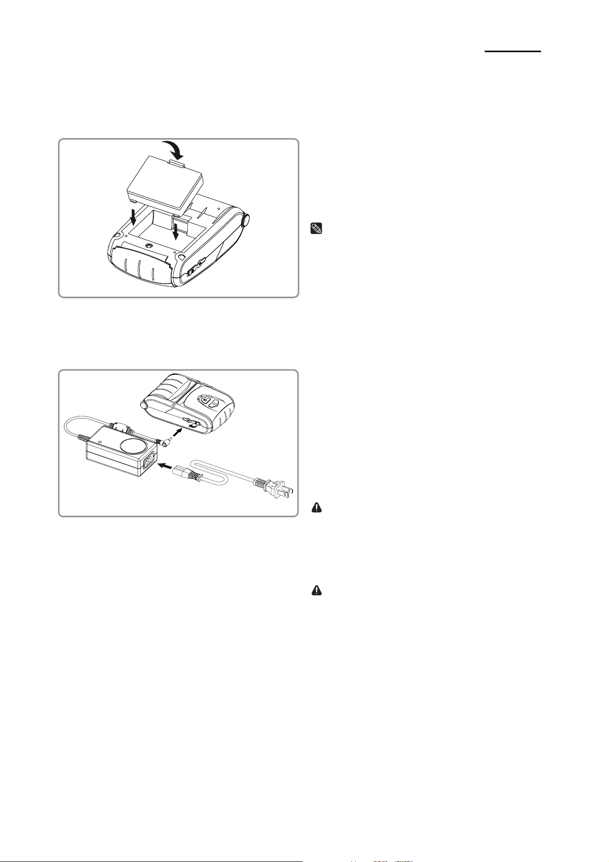
2-1 Battery Installation
2-2 Battery Charging
EM 220
1) Insert the battery on the rear side of the printer,
aligning the battery hook properly.
2) Push the battery into the slot until a snapping
sound is heard.
NOTE
As the battery is not charged at the time of purchase,
charge the battery prior to product use.
(Use the battery charger and/or the optional battery
holder.)
2-2-1 Battery Charging Usage
①
③
②
1) Turn off the printer power.
2) Connect the power cord ② to the battery charger ①.
3) Open the Interface Cap ③.
4) Connect the battery charger ① to the power
connector of the printer.
5) Plug the power cord ② into an electrical outlet.
CAUTION
The printer may incur serious damage if the battery
charger provided by Zebra is not used. Zebra is
not legally liable for any such damages. (The voltage
and electrical current specifications of the printer
and battery charger must match.)
WARNING
Turn off the power before charging the battery for
the printer.
Rev. 1.03
- 9 -
Mobile Printer Service Manual
EM 220
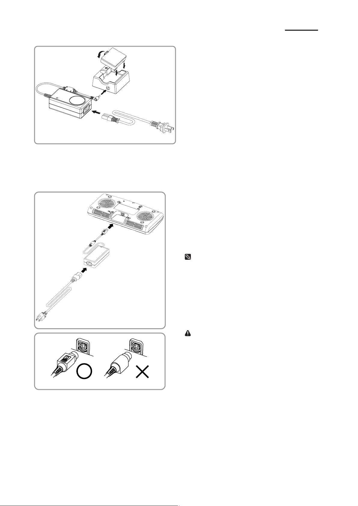
2-2-2 Battery Holder (Optional) Usage
④
③
①
2-2-3 EM Series Quad Charger (Optional) Usage
2-2-3-1 Connecting the cables
②
1) Connect the power cord to the battery charger② .
2) Connect the battery charger to the power ①
connector of the battery holder .③
3) Plug the power cord into an electrical outlet.②
4) Insert the battery into the battery holder until ④③
a snapping sound is heard.
1) Connect the power cord to the adaptor, and
Connect the adaptor to the power connector of the
Quad Charger.
2) Plug the power cord into a power Outlet. Input
power is 100 ~ 240VAC, 50/60Hz, 1.4A.
NOTE
When power is supplied, the amber and green LED
turn on for two seconds.
WARNING
Use only designated AC/DC adaptor (12VDC, 5A)
①
Rev. 1.03
- 10 -
Mobile Printer Service Manual
EM 220
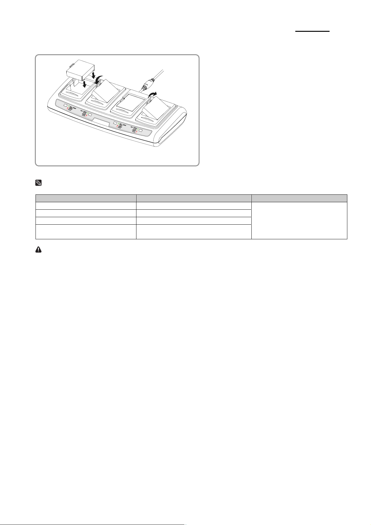
2-2-3-2 Battery Charging
NOTE
Battery charging status descriptions are as follows.
LED Charging Status Charge Time
Red LED On Charging
Green LED Blinking Over 80% Charged
Green LED On Fully Charged
Red LED Blinking
CAUTION
If the red LED is blinking, try removing and then reinserting the battery.
If the red LED continues to blink, please consult the reseller.
Error
Replace or Reinstall Battery
1) Fasten batteries via the battery
hooks into the Quad Charger as
shown above.
2) Push the battery in until a snapping
sound is emitted.
3) Charging begins as soon as the
battery is completely inserted.
Batteries are charged to 8.4VDC, 0.8A.
4) Push the hook and pull up to extract
the battery.
2.5 hours
Rev. 1.03
- 11 -
Mobile Printer Service Manual
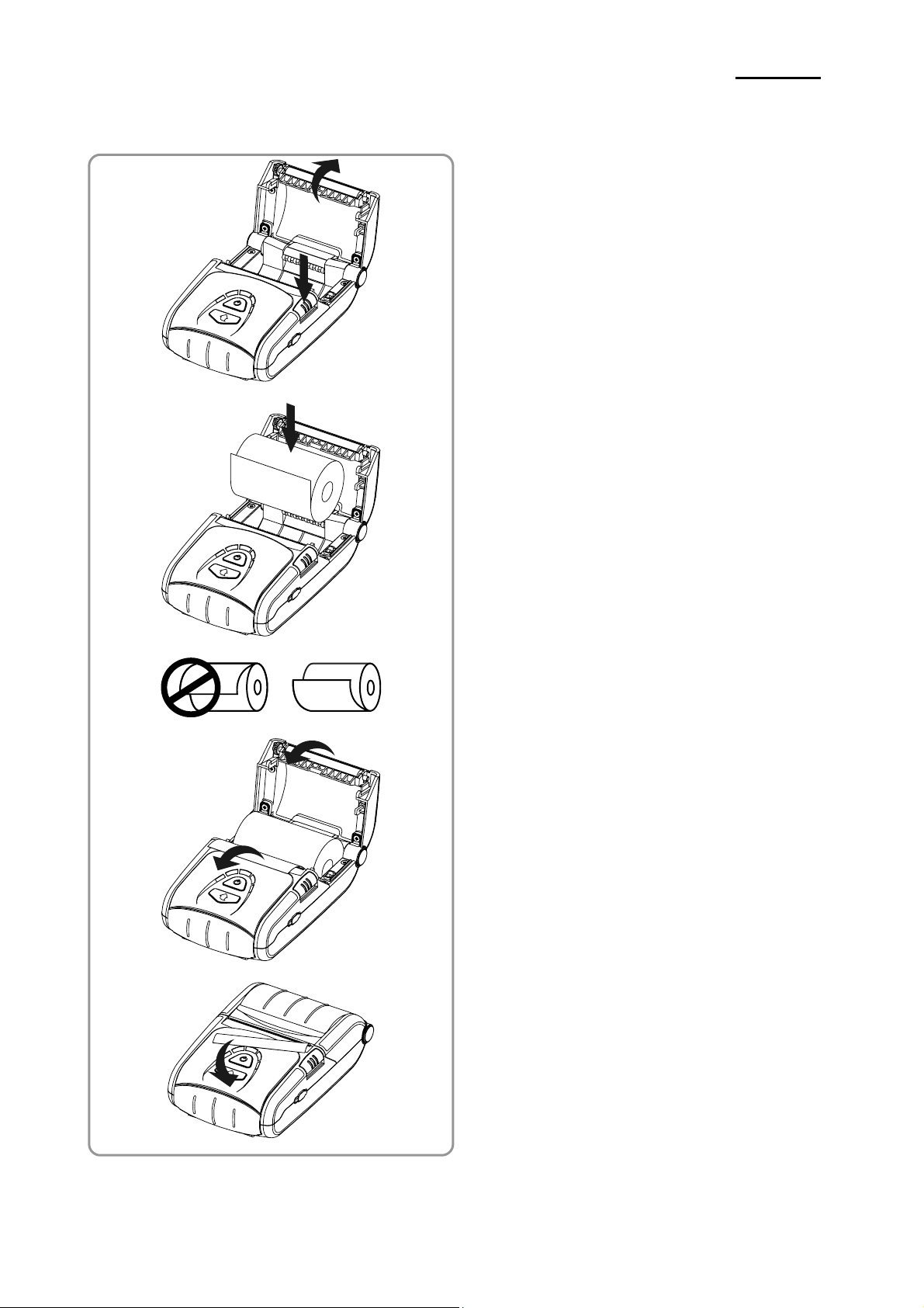
2-3 Paper Installation
EM 220
1) Press the Open button to open the paper cover.
2) Insert the paper as shown in the image.
(Remove any remaining core of a fully used paper roll.)
3) Ensure that you to align the paper correctly.
4) Pull the paper out as shown in the image and
close the paper cover.
5) Tear off any excess paper in the direction of the
side of the printer.
Rev. 1.03
- 12 -
Mobile Printer Service Manual
EM 220
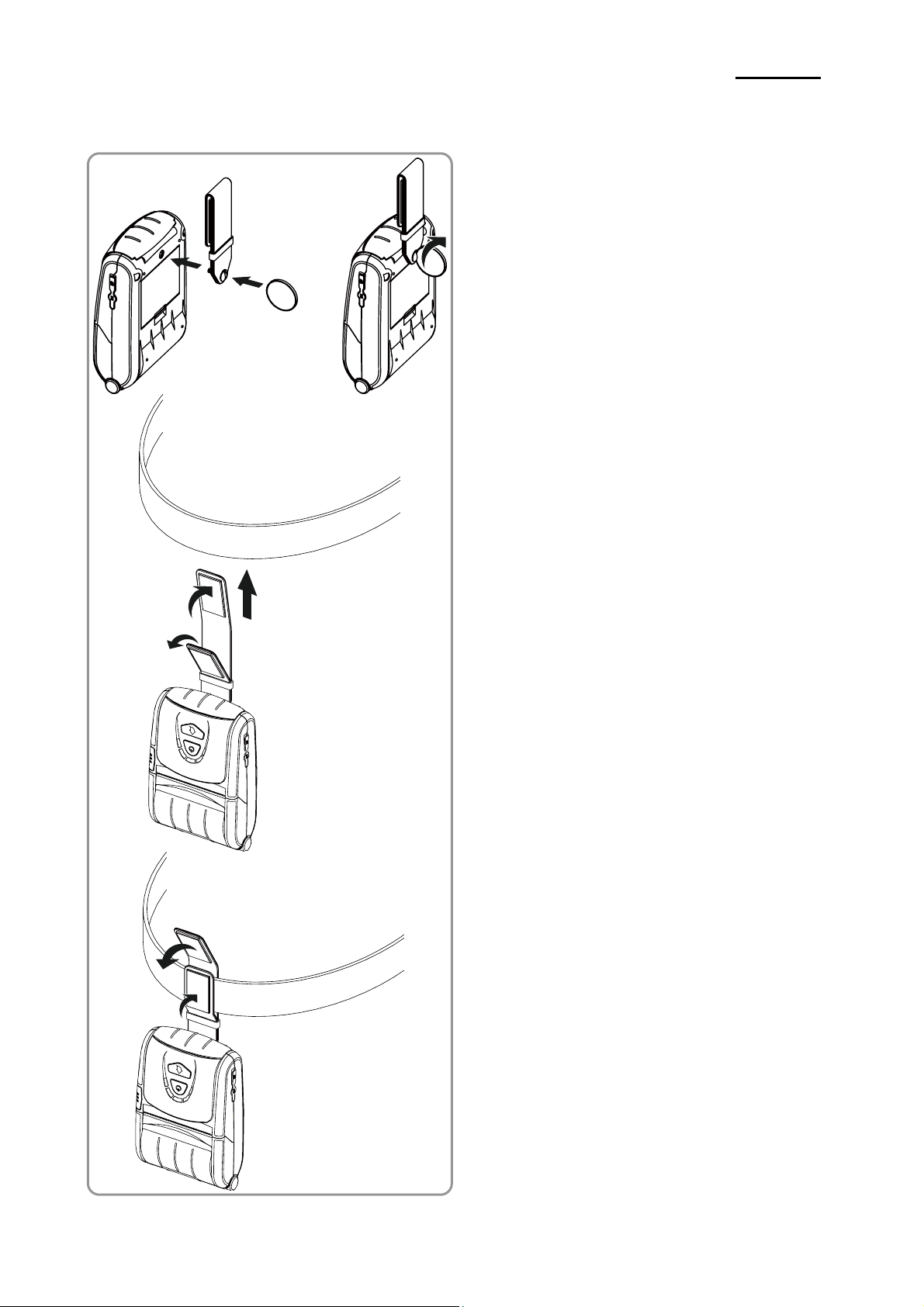
2-4 Belt Strap Usage
Belt Strap
Coin
Belt
1) Insert the belt strap screw into the belt strap hole.
2) Use a coin to tighten the belt strap screw as
shown in the image.
3) Undo the belt strap Velcro.
4) Fasten the belt strap to a belt.
5) Close the Velcro as shown in the image.
Rev. 1.03
Belt
- 13 -
Mobile Printer Service Manual
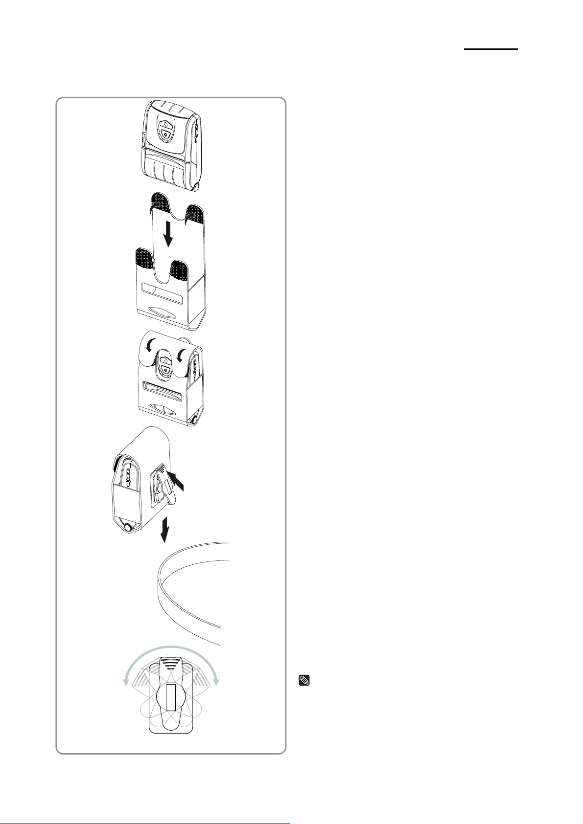
2-5 Leather Case (Optional) Usage
Belt
EM 220
1) Undo the Velcro.
2) Place the printer into the leather case following
the direction shown in the image.
3) Close the Velcro.
4) Affix to a belt using the clip at the rear of the case.
NOTE
The clip on the leather case can be rotated two
stages by 30° per stage(maximum 60°).
Rev. 1.03
- 14 -
Mobile Printer Service Manual
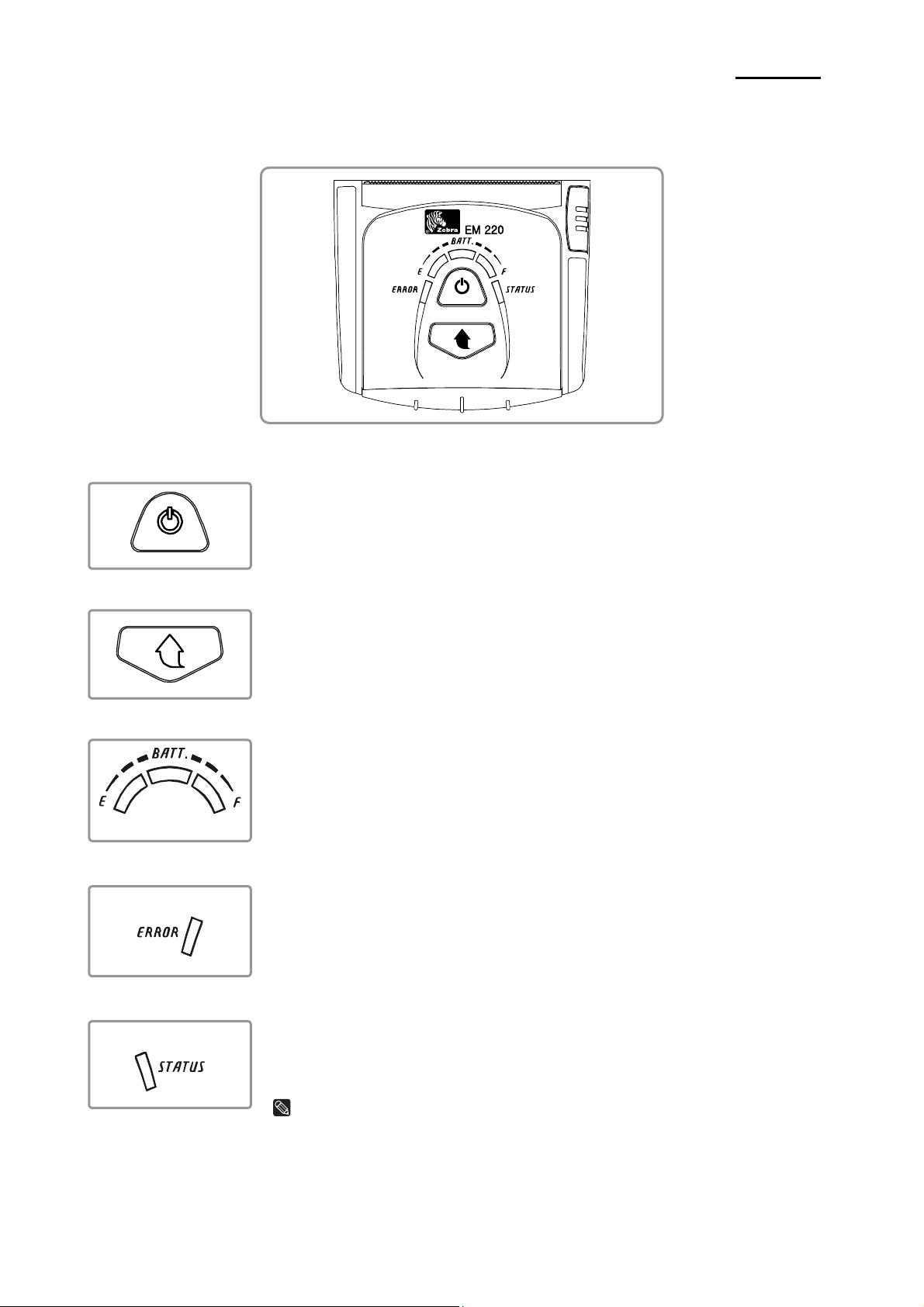
2-6 Control Panel Usage
EM 220
• Power Button
This button is used to turn the printer on and off.
When the printer is off, pressing this button for approximately 2 seconds will turn
the power on. When the printer is on, pressing this button for approximately 2
seconds will turn the power off.
• Paper Feed Button
• Battery Status LED (Blue or Red)
Paper output can be done manually by pressing this button.
In addition, self-testing and Hexadecimal Dumping can be done.
1) Refer to “2-10 Self-Test” for self-test information.
2) Refer to the service manual regarding Hexadecimal Dumping.
1) If three blue LEDs are lit, the battery is fully charged.
2) If two blue LEDs are lit, the battery is half charged.
3) If one blue LED is lit, the battery is at the lowest charge level.
4) If the red LED is lit, the battery must be charged or replaced.
• Error LED (Red)
1) If the red LED is lit, the paper cover is open.
2) If the red LED is blinking, either the paper has been fully used or the print head
is overheated. (Fill with paper or turn the printer off for at least 10 minutes.)
3) If the red LED continues to blink, it may indicate a more serious problem with
the product, and thus an authorized service dealer should be consulted.
• Bluetooth LED (Green)
1) If the green LED turns on in unison with the battery status LED, the printer can
be used with Bluetooth wireless communication.
2) If only the green LED is lit, the printer has entered the power saving mode.
NOTE
The power saving mode is activated after the first communication, with the default
time interval being 10 seconds.
Rev. 1.03
- 15 -
Mobile Printer Service Manual
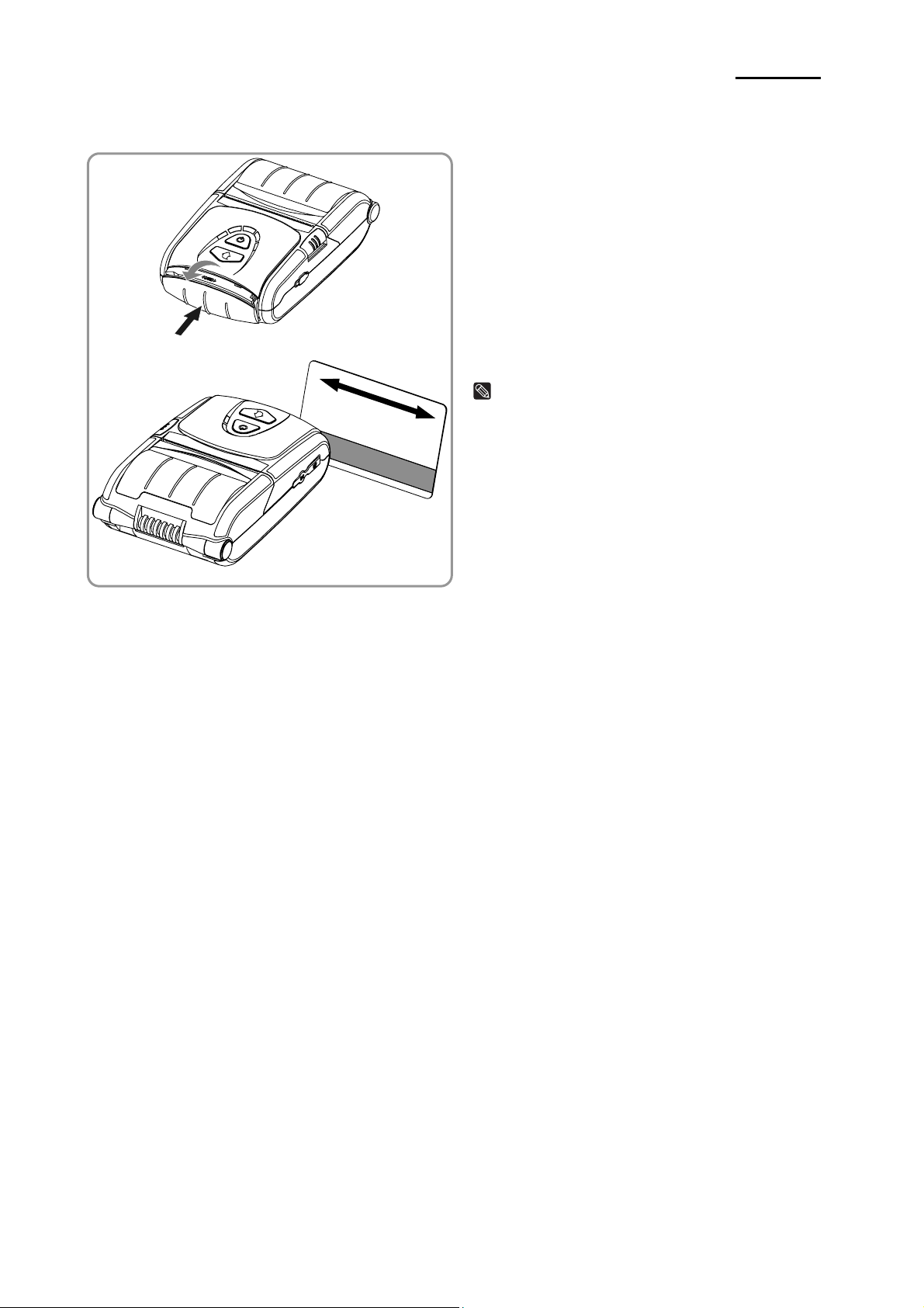
2-7 MSR Usage
EM 220
1) Press the MSR cover to open.
2) Insert the card as shown in the image and swipe
in the direction of the arrow.
(can be done in both directions)
3) When finished using, press the MSR cover to
close it.
NOTE
If the card does not register, first check to see if it is
properly aligned. When swiping the card, the
recommended swiping speed is 100 ~ 1500 mm/sec.
2-8 Self-Test
Run the self-test when first setting the printer or when encountering a problem, and check the following:
- Control Circuit, Mechanisms, Print Quality, ROM Version, and Memory Switch Settings
If no issue is found with the printer after running the self-test, examine the other devices or peripherals and
software. This function is independent of such other devices and software.
2-8-1 Self-Test Instructions
1) Turn the printer power off and close the printer paper cover.
2) Pressing the paper feed button and power button simultaneously turns the printer on.
3) The printout is produced after releasing the two buttons.
4) To add a printout of the ASCII pattern, press the paper feed button once more.
5) After the ASCII pattern is printed out, the self-test is automatically terminated.
Rev. 1.03
- 16 -
Mobile Printer Service Manual
EM 220
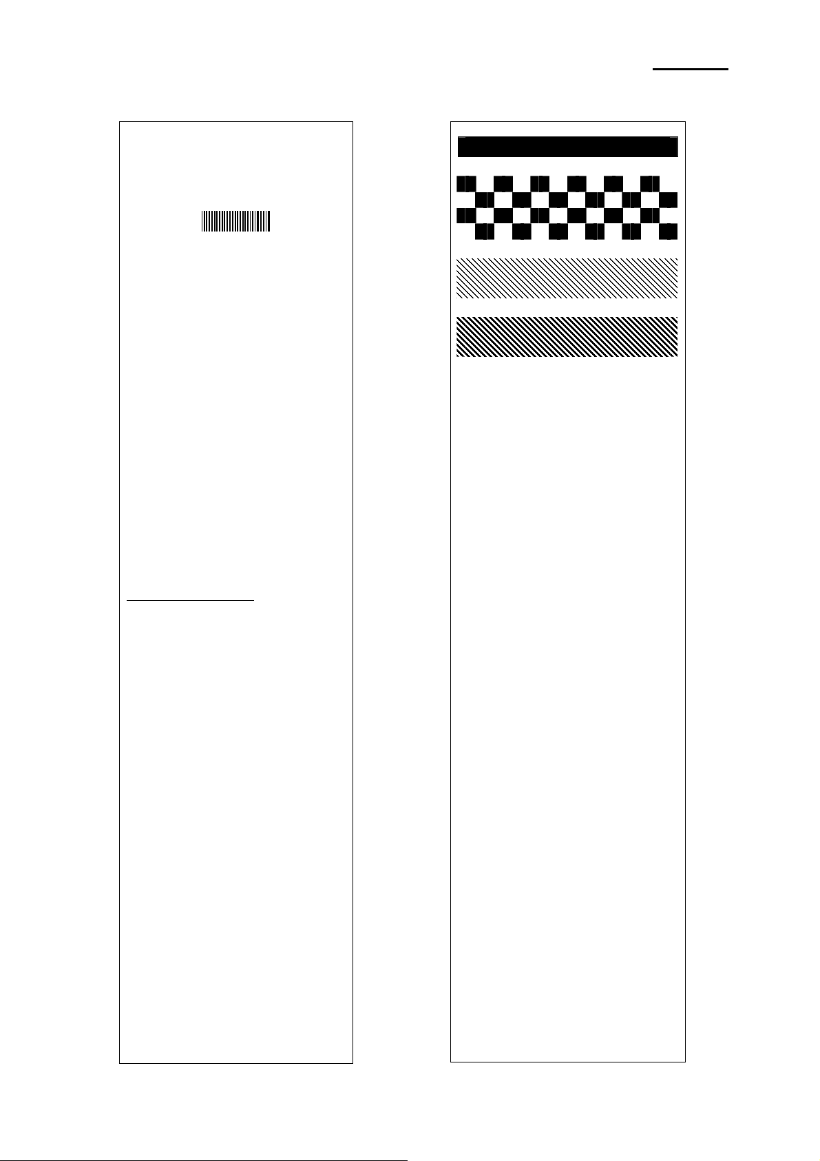
2-8-2 Self-Test Printout Sample
Boot loader version :
VER v2.01 20071005
Firmware version :
B01.00 STD 071108
Bluetooth Firmware version :
3.0.0
Bluetooth BD address :
Auth. & Encry. are enable
Connection Mode = 2
================================
Butter Capacity : 128K Bytes
Print Density : 100%
Bluetooth Interface
- Baud rate : 115200 bps
Serial Interface
- Baud rate : 115200 bps
Data bits : 8 bits
Parity : None
Stop bit : 1 bit or more
Handshaking : DTR/DSR
Default Codepage : PC437
Print Speed : 80mm/s
Double byte character mode:Off
Busy printer buffer full
Font : 12 x 24
Paper out Bell : Off
Low Battery Buzzer : On
Power off time : 15 Min
Idle mode time : 10 Sec
Two Dimension Symbol :
- Selected PDF417 symbol
- Selected DATAMATRIX symbol
- Selected MAXI code symbol
- Selected QR code symbol
MSR read mode : Auto TRACK1/2/3
Memory switch setup status
Memory S/W1
1 2 3 4 5 6 7 8
ON
OFF
Memory S/W2
1 2 3 4 5 6 7 8
ON
OFF
Memory S/W3
1 2 3 4 5 6 7 8
ON
OFF
Memory S/W5 (Power off time)
1 2 3 4 5 6 7 8
ON
OFF
Memory S/W6 (Idle time)
1 2 3 4 5 6 7 8
ON
OFF
Memory S/W7
1 2 3 4 5 6 7 8
ON
OFF
Memory S/W8
1 2 3 4 5 6 7 8
ON
OFF
Memory S/W Serial condition
1 2 3 4 5 6 7 8
ON
OFF
001901223194
If you want to continue
SELF-TEST printing,
please press FEED button.
ASCII
!"#$%&'()*+,-./0123456789:;<=>?@
"#$%&'()*+,-./0123456789:;<=>?@A
#$%&'()*+,-./0123456789:;<=>?@AB
$%&'()*+,-./0123456789:;<=>?@ABC
%&'()*+,-./0123456789:;<=>?@ABCD
&'()*+,-./0123456789:;<=>?@ABCDE
'()*+,-./0123456789:;<=>?@ABCDEF
()*+,-./0123456789:;<=>?@ABCDEFG
)*+,-./0123456789:;<=>?@ABCDEFGH
*+,-./0123456789:;<=>?@ABCDEFGHI
+,-./0123456789:;<=>?@ABCDEFGHIJ
,-./0123456789:;<=>?@ABCDEFGHIJK
-./0123456789:;<=>?@ABCDEFGHIJKL
./0123456789:;<=>?@ABCDEFGHIJKLM
/0123456789:;<=>?@ABCDEFGHIJKLMN
0123456789:;<=>?@ABCDEFGHIJKLMNO
123456789:;<=>?@ABCDEFGHIJKLMNOP
23456789:;<=>?@ABCDEFGHIJKLMNOPQ
3456789:;<=>?@ABCDEFGHIJKLMNOPQR
456789:;<=>?@ABCDEFGHIJKLMNOPQRS
56789:;<=>?@ABCDEFGHIJKLMNOPQRST
6789:;<=>?@ABCDEFGHIJKLMNOPQRSTU
789:;<=>?@ABCDEFGHIJKLMNOPQRSTUV
89:;<=>?@ABCDEFGHIJKLMNOPQRSTUVW
9:;<=>?@ABCDEFGHIJKLMNOPQRSTUVWX
PC437
ЗьйвдаезклипомДЕЙжЖфцтыщяЦЬ¢£¥
ьйвдаезклипомДЕЙжЖфцтыщяЦЬ¢£¥
йвдаезклипомДЕЙжЖфцтыщяЦЬ¢£¥Ptƒбн
вдаезклипомДЕЙжЖфцтыщяЦЬ¢£¥Ptƒбну
даезклипомДЕЙжЖфцтыщяЦЬ¢£¥
аезклипомДЕЙжЖфцтыщяЦЬ¢£¥
езклипомДЕЙжЖфцтыщяЦЬ¢£¥PtƒбнуъсС
зклипомДЕЙжЖфцтыщяЦЬ¢£¥PtƒбнуъсСª
клипомДЕЙжЖфцтыщяЦЬ¢£¥PtƒбнуъсСªº
липомДЕЙжЖфцтыщяЦЬ¢£¥PtƒбнуъсСªº¿
ипомДЕЙжЖфцтыщяЦЬ¢£¥PtƒбнуъсСªº¿
помДЕЙжЖфцтыщяЦЬ¢£¥PtƒбнуъсСªº¿
омДЕЙжЖфцтыщяЦЬ¢£¥PtƒбнуъсСªº¿ ½
мДЕЙжЖфцтыщяЦЬ¢£¥PtƒбнуъсСªº¿ ½¼
ДЕЙжЖфцтыщяЦЬ¢£¥PtƒбнуъсСªº¿ ½¼¡
ЕЙжЖфцтыщяЦЬ¢£¥PtƒбнуъсСªº¿ ½¼¡«
ЙжЖфцтыщяЦЬ¢£¥
жЖфцтыщяЦЬ¢£¥
ЖфцтыщяЦЬ¢£¥PtƒбнуъсСªº¿ ½¼¡«»
фцтыщяЦЬ¢£¥PtƒбнуъсСªº¿ ½¼¡«»
цтыщяЦЬ¢£¥PtƒбнуъсСªº¿ ½¼¡«»┃
тыщяЦЬ¢£¥PtƒбнуъсСªº¿ ½¼¡«»┃
ыщяЦЬ¢£¥
ùÿÖÜ¢£¥
яЦЬ¢£¥PtƒбнуъсСªº¿½¼¡«»┃
Pt
ƒбнуъсСªº¿ ½¼¡«»┃
Pt
ƒбнуъсѪº¿ ½¼¡«»┃
Pt
ƒáíóú
Pt
ƒбнуъс
Pt
ƒбнуъсСªº¿ ½¼¡«»
Pt
ƒбнуъсСªº¿ ½¼¡«»
Pt
Pt
ć
ƒ
Rev. 1.03
- 17 -
Mobile Printer Service Manual
 Loading...