

Zebra Eltron P300, Eltron P310, Eltron P600, Eltron P400, Eltron P420 Programmer's Manual
...Page 1

Card Printer
Programmer’s
Manual
CP PARD RINTER RODUCTS
©1999 Zebra Technologies Corporation.
User’s Manual No. 980081-001 Rev. F
Page 2

Page 3

FOREWORD
This manual contains installation and operation information for the Eltron Series card printers
manufactured by Zebra Technologies Corporation, Camarillo, California.
RETURN MATERIALS AUTHORIZATION
Before returning any equipment to Zebra Technologies Corporation for in-warranty or
out-of-warranty repair, contact Repair Administration for a Return Materials Authorization (RMA)
number. Repack the equipment in the original packing material and mark the RMA number
clearly on the outside. Ship the equipment, freight prepaid, to the address listed below:
For U.S.A and Latin America:
Zebra Technologies Corporation
Eltron Card Printer Products
1001 Flynn Road
Camarillo, CA. 93021-8706. U.S.A.
Phone: +1 (805) 579-1800
FAX: +1 (805) 579-1808
Toll Free in US: (800) 452 4056
For Europe, Asia, and Pacific:
Zebra Technologies Corporation
Eltron Card Printer Products
Zone Indutrielle, Rue d'Amsterdam
44370 Varades, France
Phone: +33 (0) 240 097 070
FAX: +33 (0) 240 834 745
COPYRIGHT NOTICE
This document contains information proprietary to Zebra Technologies Corporation. This docu
ment and the information contained within is copyrighted by Zebra Technologies Corporation
and may not be duplicated in full or in part by any person without written approval from Zebra.
While every effort has been madeto keep the information contained within currentand accurate
as of the date of publication, no guarantee is given or implied that the document is error-free or
that it isaccuratewithregardtoany specification. Zebra reserves theright tomake changes,for the
purpose of product improvement, at any time.
TRADEMARKS
Eltron is a trademark ofEltron International Incorporated. Windows and MS-DOS are registered
trademarks ofMicrosoft Corp.All other marks are trademarksor registered trademarks of their re
spective holders.
980081-001 Rev. F iii
-
-
Page 4

WARRANTY INFORMATION
WE NEED TO HEAR FROM YOU!
To Establish Your Warranty Period And Provide Access To Technical Support, Send Us your
Product Registration Card Today!
Zebra warrants the mechanism, control electronics and power supply, under normal use and ser
vice, tobe freefrom defects in materialand workmanshipfor a period of twelve(12) monthsfrom
the date ofpurchase bythe end user. Zebrawarrants theprint head, undernormal useand service,
to be free from defects in material and workmanship for a period of twelve (12) months or 100k
passes (whichever occurs first) from the date of purchase by the end user. Proof of purchase or
product registration isrequired. Ifproof ofpurchase orproduct registration cannot be established,
shipment date to the original buyer (dealer or distributor) willbe usedto establishthe warrantype
riod.
Failure to exercisecaution toprotect theequipment from electrostatic discharge damage, adverse
temperature and humidityconditions orphysical abusemay void thewarranty. Failureto useonly
Eltron approved media may void the warranty. Zebra will, at its option, repair or replace the
equipment or any parts which are determined to be defective within this warranty period, and
which are returned to Zebra F.O.B. factory of origin.
The warranty set forth above is exclusive and no other warranty, whether written or oral, is expressed or implied. Zebra specifically disclaims the implied warranties of merchantability and fitness for a particular purpose.
-
-
iv 980081-001 Rev. F
Page 5

TABLE OF CONTENTS
INTRODUCTION . . . . . . . . . . . . . . . . . . . . . . 1-1
Features . . . . . . . . . . . . . . . . . . . . . . . . . . . . 1-1
Related Publications:. . . . . . . . . . . . . . . . . . . . . . 1-8
Conventions . . . . . . . . . . . . . . . . . . . . . . . . . . 1-9
Basic Command Syntax . . . . . . . . . . . . . . . . . . . . 1-10
Command Editor . . . . . . . . . . . . . . . . . . . . . . . 1-11
Memory Arrangements. . . . . . . . . . . . . . . . . . . . . 1-12
Bit-Map Compression Algorithm . . . . . . . . . . . . . . . . 1-13
Data-to Card Mapping . . . . . . . . . . . . . . . . . . . . . 1-16
Control Commands . . . . . . . . . . . . . . . . . . . . . . 1-21
Card Handling Process . . . . . . . . . . . . . . . . . . . . 1-22
Batch Processing. . . . . . . . . . . . . . . . . . . . . . . . 1-23
Sample Card. . . . . . . . . . . . . . . . . . . . . . . . . . 1-23
Port Signals . . . . . . . . . . . . . . . . . . . . . . . . . . 1-24
Error Line Coding . . . . . . . . . . . . . . . . . . . . . . . 1-24
COMMAND REFERENCE . . . . . . . . . . . . . . . . . . 2-1
Command List . . . . . . . . . . . . . . . . . . . . . . . . . 2-2
. Command - Clear Error Status . . . . . . . . . . . . . . . . 2-5
R Command - Reset . . . . . . . . . . . . . . . . . . . . . . 2-6
MC Command - Clear Media Path . . . . . . . . . . . . . . 2-7
V Command - Check Printer Type/Version . . . . . . . . . 2-8
!V Command - Return Operational Parameter . . . . . . . . . 2-9
+O Command - Print Offset X-axis . . . . . . . . . . . . . . 2-10
+OY Command - Print Offset Y-axis . . . . . . . . . . . . . 2-11
+OLP Command - Offset Overlaminate Patch . . . . . . . . 2-12
+EC Command - End of Print . . . . . . . . . . . . . . . . 2-13
+LAYER Command - Choose Number of Card Layers . . . . 2-14
!R Command - Print Head Resistance . . . . . . . . . . . . . 2-15
M/m Commands - Multiple Command . . . . . . . . . . . . 2-16
MI Command - Input Card To Print . . . . . . . . . . . . . . 2-17
MIB Command - Reverse Card To Card Feeder . . . . . . . 2-18
ME Command - Exit Card To Output Tray . . . . . . . . . . 2-19
MB Command - Return Card To Card Feeder . . . . . . . . 2-20
MO Command - Exit Card To Output Tray . . . . . . . . . . 2-21
!FF Command - Set Ribbon Sequence . . . . . . . . . . . . 2-22
+RIB Command - Set Ribbon Type . . . . . . . . . . . . . 2-23
!M Command - Move Print Head Up . . . . . . . . . . . . . 2-25
!D Command - Move Print Head Down . . . . . . . . . . . . 2-26
!SA Command - Self Adjust . . . . . . . . . . . . . . . . . . 2-27
CLNCARD Command - Establish Cleaning Card Sequence . . 2-28
CLEAN Command - Start Cleaning Card Sequence . . . . . . 2-29
+BS Command - Set Black Speed . . . . . . . . . . . . . . 2-30
IM Command - Print Color Test Card . . . . . . . . . . . . . 2-31
980081-001 Rev. F v
Page 6

IMB Command - Print Black Test Card . . . . . . . . . . . . . 2-32
A Command - Print Test Card . . . . . . . . . . . . . . . . . . 2-33
F/vF Command - Clear Monochrome Image Buffers . . . . . . . 2-34
G/vG Command - Initialize Monochrome Graphic (B/W) . . . . 2-35
O/vO Commands - Load Single Line Bit-map (Mono.) . . . . . 2-36
Z/vZ Commands - Load Bit-map (Monochrome) . . . . . . . . 2-38
P/vP Commands - Write Dot (Monochrome) . . . . . . . . . . 2-40
L/vL Command - Write Line (Monochrome) . . . . . . . . . . . 2-41
C/vC Command - Write Box (Monochrome) . . . . . . . . . . 2-42
D/vD Commands - Write Diagonal (Monochrome) . . . . . . . 2-43
T/vT Commands - ASCII Text (Monochrome) . . . . . . . . . . 2-44
B/vB Command - Write Bar Code . . . . . . . . . . . . . . . . 2-46
I Command - Print Monochrome Graphics . . . . . . . . . . . 2-48
J Command - Print Multiple Monochrome Cards . . . . . . . . 2-49
+C Command - Adjusts Monochrome Intensity . . . . . . . . . 2-50
IV Command - Print Clear Veneer . . . . . . . . . . . . . . . . 2-51
+CV Command - Adjust Clear Veneer Intensity . . . . . . . . 2-52
$F Command - Clear Color Image Buffers . . . . . . . . . . . . 2-53
$FP Command - Clear Specified Bit-Maps . . . . . . . . . . . . 2-54
PS Command - Download Color Image Buffer . . . . . . . . . 2-55
GS Command - Download Color Graphic . . . . . . . . . . . . 2-56
+$L Command - Adjust Color Intensity . . . . . . . . . . . . . 2-57
+$C Command - Adjust Color Contrast . . . . . . . . . . . . 2-58
IS Command - Print Color Graphic . . . . . . . . . . . . . . . 2-59
IH Command - Print Hologram . . . . . . . . . . . . . . . . . 2-60
+CH Command - Adjust Hologram Intensity . . . . . . . . . . 2-61
MF Command - Rotate Card To Duplex . . . . . . . . . . . . 2-62
&R Command - Reset Magnetic Encoder . . . . . . . . . . . . 2-63
&E Command - Write Single Track . . . . . . . . . . . . . . . 2-64
&B Command - Write Buffer Single Track . . . . . . . . . . . . 2-65
&E* Command - Write Track Buffers . . . . . . . . . . . . . . 2-66
&L Command - Read Single Track . . . . . . . . . . . . . . . 2-67
&W Command - Change Encoding Direction . . . . . . . . . . 2-68
&D Command - Change Track Density . . . . . . . . . . . . . 2-69
&CDER Command - Read Custom Track Data . . . . . . . . . 2-70
&CDEW Command - Write Custom Track Data . . . . . . . . . 2-72
&T Command - Mag. Encoder - Eject Card . . . . . . . . . . . 2-74
&C Command - Set Coercivity. . . . . . . . . . . . . . . . . . 2-75
MS Command - Move To Smart Card Programmer . . . . . . . 2-76
MRB Command - Move Card to Rejected Box . . . . . . . . . . 2-77
+OS Command - Smart Card Y-axis Offset . . . . . . . . . . . 2-78
SXY Command - Center Image Maps . . . . . . . . . . . . . . 2-79
+OCL Command - Offset Contactless . . . . . . . . . . . . . . 2-80
MCL Command - Move Contactless . . . . . . . . . . . . . . . 2-81
CRB Command - Set Counter for Rejected Box . . . . . . . . . 2-82
+RB Command - Set Rejected Box . . . . . . . . . . . . . . . 2-83
vi 980081-001 Rev. F
Page 7

+B Command - Serial Interface Rate . . . . . . . . . . . . . 2-84
E Command - Retransmit Last Response . . . . . . . . . . . 2-85
+X Command - Change Command Initiator . . . . . . . . . 2-86
!X Command - Check Command Initiator . . . . . . . . . . . 2-87
&P Command - Check Card Present - Encoder . . . . . . . . 2-88
%CLN Command - Check Due-for-Cleaning Parameters . . . 2-89
SF Command - Synchronize Film (Overlaminate) . . . . . . . 2-90
TF Command - Film Type . . . . . . . . . . . . . . . . . . 2-91
+TC Command - Set Temperature . . . . . . . . . . . . . . 2-92
+DLAMI Command - Set Lamination Configuration . . . . . 2-93
+VL Command - Set Lamination Speed . . . . . . . . . . . 2-98
+VC Command - Reduce Color Print Speed . . . . . . . . . 2-99
RCBC Command - Reset Card Count of Reject Hopper . . . . 2-100
Appendix A . . . . . . . . . . . . . . . . . . . . . . . . . A-1
Resident Fonts . . . . . . . . . . . . . . . . . . . . . . . . . A-2
Code 39 (Code 3 of 9). . . . . . . . . . . . . . . . . . . . . A-3
Standard 2 of 5 (Code 2/5) . . . . . . . . . . . . . . . . . . A-4
Interleaved 2 Of 5 (Code I 2/5) . . . . . . . . . . . . . . . . A-5
UPC-A . . . . . . . . . . . . . . . . . . . . . . . . . . . . . A-6
EAN-8 . . . . . . . . . . . . . . . . . . . . . . . . . . . . . A-7
EAN-13 . . . . . . . . . . . . . . . . . . . . . . . . . . . . A-8
Code 128 Subsets B & C . . . . . . . . . . . . . . . . . . . A-9
EAN International Regulation Agencies . . . . . . . . . . . . A-11
Appendix B . . . . . . . . . . . . . . . . . . . . . . . . . B-1
Parallel Port Printer Data Handshake Signal Lines . . . . . . . B-1
Parallel Port Printer Error Response . . . . . . . . . . . . . . B-1
Serial Port Printer Data Handshake . . . . . . . . . . . . . . B-2
Serial Port Printer
Error Response . . . . . . . . . . . . . . . . . . . . . . . . B-2
Appendix C . . . . . . . . . . . . . . . . . . . . . . . . . C-1
Magnetic Encoders. . . . . . . . . . . . . . . . . . . . . . . C-1
Encoder Operation . . . . . . . . . . . . . . . . . . . . . . C-2
Data Errors . . . . . . . . . . . . . . . . . . . . . . . . . . C-3
Encoder Default Configuration. . . . . . . . . . . . . . . . . C-3
Basic Commands . . . . . . . . . . . . . . . . . . . . . . . C-4
Advanced Encoder Commands . . . . . . . . . . . . . . . . C-4
Resetting The Encoder To ANSI/ISO Track Defaults . . . . . . C-5
Change Track Density . . . . . . . . . . . . . . . . . . . . . C-6
Changing Read Configuration . . . . . . . . . . . . . . . . . C-6
Changing Write Configurations . . . . . . . . . . . . . . . . C-6
Custom ISO Data . . . . . . . . . . . . . . . . . . . . . . . C-7
Unique Custom Data Formats . . . . . . . . . . . . . . . . . C-7
980081-001 Rev. F vii
Page 8

Appendix D . . . . . . . . . . . . . . . . . . . . . . . . . D-1
Sample P600 Command Sequence . . . . . . . . . . . . . . D-2
Appendix E . . . . . . . . . . . . . . . . . . . . . . . . . E-1
Sample Max3000 Command Sequences. . . . . . . . . . . . E-2
Sample Max3300 Command Sequences. . . . . . . . . . . . E-4
viii 980081-001 Rev. F
Page 9

INTRODUCTION
This manual describes programming commands
that control operations and specify data for the following card printer models:
· P3xx Monochrome (P300 and P310
·
P3xx Color (P300 and P310)
·
P4xx Duplex Color (P400 and P420)
·
P500 Duplex Color with Laminator
·
P600 Dual Print Station Duplex Color
·
Max SecureSeries CardSystems (Max3000 and
Max3300)
Features All of the covered models can print bar-codes in
several formats and have resident scalable font de
scriptions. Also, except for the Max Secure Series,
all models can include a Smart-Card Docking Sta
tion. P310 and P420s can have a Proximity Card
docking Station. All modelsare offeredwith orwith
out a Magnetic Stripe Encoder. A Serial host inter
face is an option on the P3xx and P4xx series,
where an associated RS-232C setup Command ex
ists. Max Secure Systems all have parallel host
ports.
-
-
-
-
-
980081-001 Rev. F 1-1
Page 10

The programming commands control the printing
process by color and by ribbon material, allowing
overprinting and separate control of various multi
ple-overlay finishes.
Print Engines:
P300 and P400—P300 print engine and
·
P300 print engine plus duplexer,respectively
P310 and P420—P310 print engine and
·
P310 print engine plus duplexer, respec
tively
P500 and P600—P300 print engine plus
·
Laminator and dual P300 print engines, re
spectively
Max Secure—P300 printengines on all mod
·
els.
Significant model/configuration differences
related to programming include the following:
P3xx Monochrome card printers have a limited
command set along with an image buffer sufficient
for a one-bit image mapping depth. Only imaging
using the thermal transfer methodology can occur.
For gray-scale images, host software must produce
multiple-dot pixel matrixes sized for the desired
gray-scale range (e.g., a four-by-four dot pixel matrix can produce 16 levels of gray plus white, [(4 x
2
/16 + white]).
4)
-
-
-
-
P3xx Color card printers employ dye sublimation
methodology for color imaging andthermal transfer
methodology for imaging from resin monochrome
ribbons or ribbon panels. A yellow, magenta, and
cyan imaging sequence occurs using five-bit-perdot data for imaging with three associated ribbon
panels.
The black panels on Eltron-supplied ribbons with
color panels have a resin coating that particularly
suits bar-code and other solid image printing (i.e.,
no gray scale). However, resinresponds poorly as a
dye sublimation printmedium. Therefore,the black
used for gray-scale imaging comes from formula
tions of yellow, magenta, and cyan (YMC), which
1-2 980081-001 Rev. F
-
Page 11

means dye-sublimation black also has a five-bitper-dot range (32 levels of gray). If the need for a
resin-panel-generated gray scale should ever be
come necessary, host software must generate
multiple-dot pixel matrixes as with the P3xx Mono
chrome.
Standard P3xx Color Card Printers have two
image buffers—one used for color and another
used for monochrome. The single color buffer re
quires print passes that follow each of the three
downloads associated with full-color dye
sublimation imaging. The single monochrome
buffer requires print passes following separate
downloads for resinblack and for overlay varnishin
situations that require different bit-maps. However,
because of its durability, card areas with resin im
ages may not require varnish for the associated ul
traviolet protection. Therefore, by using a reverse
imaging for varnish, thesame bit-mapused forresin
produces a varnish overlaythat omitsthe areas with
resin. Reverse imaging also means that a fullcoverage varnish can result after a clear command
sent for the monochrome buffer.
P310 (all models) and P300 Color Printers
with Extended Memory have the potential for
three color buffers and two monochrome buffers.
These buffers have the same uses as described for
the P3xx Color above. However, more buffers
means that a high probability exists that data for a
complete card image can download in a single host
access. With a complete image resident in the
printer, multiple card prints can occur at a much
faster rate.
-
-
-
-
-
980081-001 Rev. F 1-3
P4xx's have all the same implementations as the
P3xx Color, including Extended Memory as a P400
option. BecauseP4xx's havea Card-Flipassembly,
these models respond to commands related to du
plex printing. P420 Card-Flip Stations can reject
cards into an associated hopper and includes re
lated commands. P420s also have an interface that
supports the programming of Proximity Cards (also
called Contactless Cards).
P500s have all the same implementations as a
P400, including Extended Memory, Smart Card
stations, and Magnetic Encoders as options. How
-
-
-
Page 12

ever, P500s also have a Card Laminator station.
Laminators serve as heat-transfer devices for mate
rial or panels contained on Laminator Ribbons. A
variety of these kinds of ribbons exist:
Ribbons with die-cut panels can carry die-cut
·
panel sizes that substantially cover the card
Die cuts with cutouts for Smart cardcontacts,
·
and smaller die cuts that serve to avoid mag
netic stripes
Preprinted die cuts can contain security de
·
vices such as graphics, holograms, or opti
cally-encoded patches.
Laminators also servea thermal-transferfunction of
ribbon coated material instead ofthe die-cut panels.
However, only a total card application can occur.
Because the print station can have a dye sublimation ribbon witha varnishpanel, manychoices exist
for selection of protective coatings. Additional commands exist to implement Laminator use.
Whereas P3xx's and P4xx's have single CPU
boards, P500s employ two—one controls printing
and card feeds (Module 1 operations); the other
controls card flips and lamination (Module 2 operations). Because of a master-slave arrangement,
Module 1 also receives Laminator commands.
However, all commands destined for Module 2 require a #1 preface, for example:
-
-
-
-
#
1+TC165↵
P600s have two complete Print Station modules
(including associated CPU Boards) separated by a
Card-Flip assembly. Although controlled by a
common parallel host interface, both Print Stations
respond to the same command set (with some
additional positioning parameters and some
differing responses to positioning commands). To
simplify memory management, both Print Stations
have Extended Memory as a standard feature.
Overall, the same commands apply, but the Card
Feed command applies only to the print station
attached to the Card Feed assembly (Module 1).
Similarly, the Card Flip commands apply only to
the Print Station closestto theCard Output(Module
1-4 980081-001 Rev. F
Page 13

2). A communication protocol serves to direct
commands through the common parallel interface
lines to either Module.
While not being designed around a master-slave
arrangement, Module 2 commands can neverthe
less be sent to Module 1. As with P500s, Module 2
commands sent to Module1 requirea #
1 preface.
Either module can have a Smart-Card Station
and/or a Magnetic Stripe Encoder, with an
associated command set. However, Eltron
recommends Module 1 as the best place to locate
these options. Also, the faster path forcommands is
the direct route.
Max Secure Systems allhave Extended Memory
and can include the following:
Print Station Module (Max3000 or Max3300)
·
Laminator and Die Cutter Module
·
Magnetic Encoder Module
·
None of the media used in the other printer models
is intended for usein this model. Instead,the following are used:
Cards
The cards placed in the Input Hopper are
oversized White Chip Cards, either with or
without a Magnetic Stripe and with or without a printable surface.
-
An additional card material isused. This clear
material feeds from a roll, and the printer has
a Shear that delivers card-sized sections to
the card path.
Max Secure Systems use 0.022-inch thick
White Cards for two-layer laminates and
0.015-inch thick White Cards for three-layer
laminates.
980081-001 Rev. F 1-5
Page 14

Ribbons
Five imaging ribbons are offered: A YMC rib
bon for die sublimation only printing, a
YMCKr ribbon for those that need Kr (black
resin) imaging on one surface only, and a
YMCKr_Kr ribbon for those that need Kr im
ages to appear on two surfaces. Mono
chrome ribbons KsO and KrO can also be
used.
Also, destination controlof commandscan beused,
as follows:
-
-
-
#11command - directs an associated com
mand to the Print Station.
Printing occurs on Clear and White Chip Card media components. Color and black resin images can
print on the Clear Card,and Black Resinimages can
print on the White Card.
Max3000 Systems laminate the Clear and White
media into two-layer composites. These systems
cannot perform two jobssimultaneously. Forexample, the printer cannot receive downloaded data
with printing in process, and printing cannot occur
with downloading in process. Because of this, programming should employthe Moperator to concatenate printing for all panels within one command
string (e.g., M 1 IS 0[IS 1[IS 2[I[MO[MF[I[MO).
Max3300 Systems can add another Clear Card
that, while remaining unprinted, protects White
Card images, includingany securitydevices. There
fore, users can produce either two- or three-layer
composites using these systems. Unlike the
Max3000s, these systems can receive data down
loads while printing. Therefore,optimum speedcan
result by alternating downloads with print com
mands, so that one process can overlap the other.
Errors sensed during a series of downloadand print
commands results in the assertion of BUSY, during
which time, the bad card gets ejected, the ribbon
gets synchronized, and the printing sequence re
sumes using the data associated with the rejected
-
-
-
-
-
1-6 980081-001 Rev. F
Page 15

card. None of these operations require issuance of
additional commands.
The following describes a typical Max Secure
System operation:
A Clear Card feeds first. This card receives color im
aging associated with theYMC ribbonpanels, andif
desired, also from a Kr panel. After imaging, the
Clear Card goes to the output of the Print Station.
A White Card feeds next. Any image placed on this
card normally depends on the availability of an un
used Kr ribbon panel. A YMCKr ribbon used to
place a black resin image on the Clear Card would
not have a Kr panel left for imaging on the White
Card without first skipping over a whole set of color
panels. For Kr on both cards, a YMCKrKr ribbon
should be used.
After receiving any images, the White Card also
travels to the output of the Print Station and comes
to rest ontop ofthe Clear Card.As witha Max3000,
these cards go on to the Laminator. For three-layer
cards, a second Clear Card enters the card path.
This Clear Card first transitions in and out ofa Card
Flip Station before going on to the Laminator
Module. This card flip serves to place the side of the
Clear Card with the bonding agent in contact with
the White Card.
Note that Max3300s have a lever for users to select
between two- and three-layer composites. Users
must also load cards having the related thickness.
The +LAYER command also exists for use in speci
fying the number of layers.
-
-
-
980081-001 Rev. F 1-7
Card alignment occurs at the first station in the
Laminator and Die Cutter assembly. From there,
the cards get laminated and then trimmed to the
standard card size. A heatsink between theLamina
tor and the Die Cutter reduces card temperatures
that became elevated during lamination. During
this transition, a speed setting for card cooling takes
effect.
Notably, only up-facing surfaces receive images.
After lamination, an inside surface has the image
placed on the Clear Card. Viewing from the back
-
-
Page 16

side produces a mirrored picture of the Clear Card
image.
Max Secure Magnetic Encoder Modules,
when part of Max Secure Systems, receive card
composites after lamination and die cutting. En
coder commands for this printer duplicate those
used by the other printer models. For Max Secure
configurations without the Magnetic Encoder
Module, cards exit the system after a die cut. Since
the magnetic stripes on White Cards need direct
contact with read/write heads, stripeencoding must
only occur during production of two-layer cards.
Related Publications: Associated User’s and Quick Help Guides for
P-Series Printers, available in various languages
User’s and Quick Help Guides for Max Secure
Series
Associated Maintenance Manuals for P-Series
printers (Available in English Only)
Maintenance Manual for Max Secure (Available in
English Only)
-
1-8 980081-001 Rev. F
Page 17

Conventions In this manual, the following conventions apply:
Escape Key (Indicates command characters
follow)
Space Key (Delimiter used to separate com
mands from parameters and parameters
from other parameters)
p
1~pn
Required parameters that follow some com
mands, separated by space delimiters
{p
~ pn}
1
Optional Parameters
↵ Enter Key (Indicates the end of a Command
and Parameter string
→ Command string continues on next line (no
line feed at this text wrap)
data Specifies where to place data in an associ-
ated Command String
[ Linking delimiter when used with “M” and
“m” commands, which see;
Also, placed in front of [, , and ↵ to specify
data instead of control characters
# Placed after and followed by number to di-
rect command to other than module receiving command.
-
-
980081-001 Rev. F 1-9
Page 18

Basic Command
Syntax
Each command begins with a Command Initiator
(the “Escape” character). For some models, direct
ing characters follow the Escape character.
-
The Command Initiator serves to mark the charac
ter(s) immediately following as command
characters. Command characters varybetween one
and seven characters (or up toseven bytes of hexa
decimal data).
Some commands then haveone or more additional
parameters to supply the printer with information
necessary to complete the command. A “Space”
character delineates individual command control
parameters. The following Text command shows a
typical example.
Each command line requires a Carriage Return (↵)
character (13 dec. or 0D hex.). A single Line Feed
(LF) character (Dec. 10 or 0A Hex.) is ignored by
the printer when it immediately follows the command terminating Carriage Return. Most PC based
systems send a CR/LF when the Enter key is
pressed.
Command Name
WRITE TEXT
Tp1p2p3p4p5p6p7data↵
Parameters
ASCII Programming Code
Command
T 100 100 0 1 20 30 1 Text↵
Text
-
-
1B54203130302031303020302031203230203330203120546578740D
Escape (Command Initiator)
1-10 980081-001 Rev. F
Hexadecimal Programming Code
Carriage Return (Command Terminator)
Page 19
Command Editor Any ASCII based text editor can serve tocreate sim
ple command files. In the DOS environment, MSDOS EDIT offersa good choice.To execute the file,
use the Print command from the editor, or from
DOS, the COPY command, to send the file to the
printer. Examples using the COPY command are:
COPY file name.ext LPT1↵
or
COPY file name.ext COM1↵
-
For more information on theuse of the COPYcom
mand, refer to a DOS software manual.
Some text editingprograms cancause printer errors
by adding extra characters or by changing existing
characters when generating a near ASCII formatted
file.
Example: A commonASCII editor,BRIEF, changes
all NUL charactersto the SPACEor TAB characters
with a file save. The graphic data for print intensity
level “0" is the NUL character. This causes the resulting file to print with horizontal lines in all graphics with solid white, i.e., no print, areas. Other
editors may add a SUB character (Dec. 26 or 1A
Hex.), which causes the printer to error.
-
980081-001 Rev. F 1-11
Page 20
Memory
Arrangements
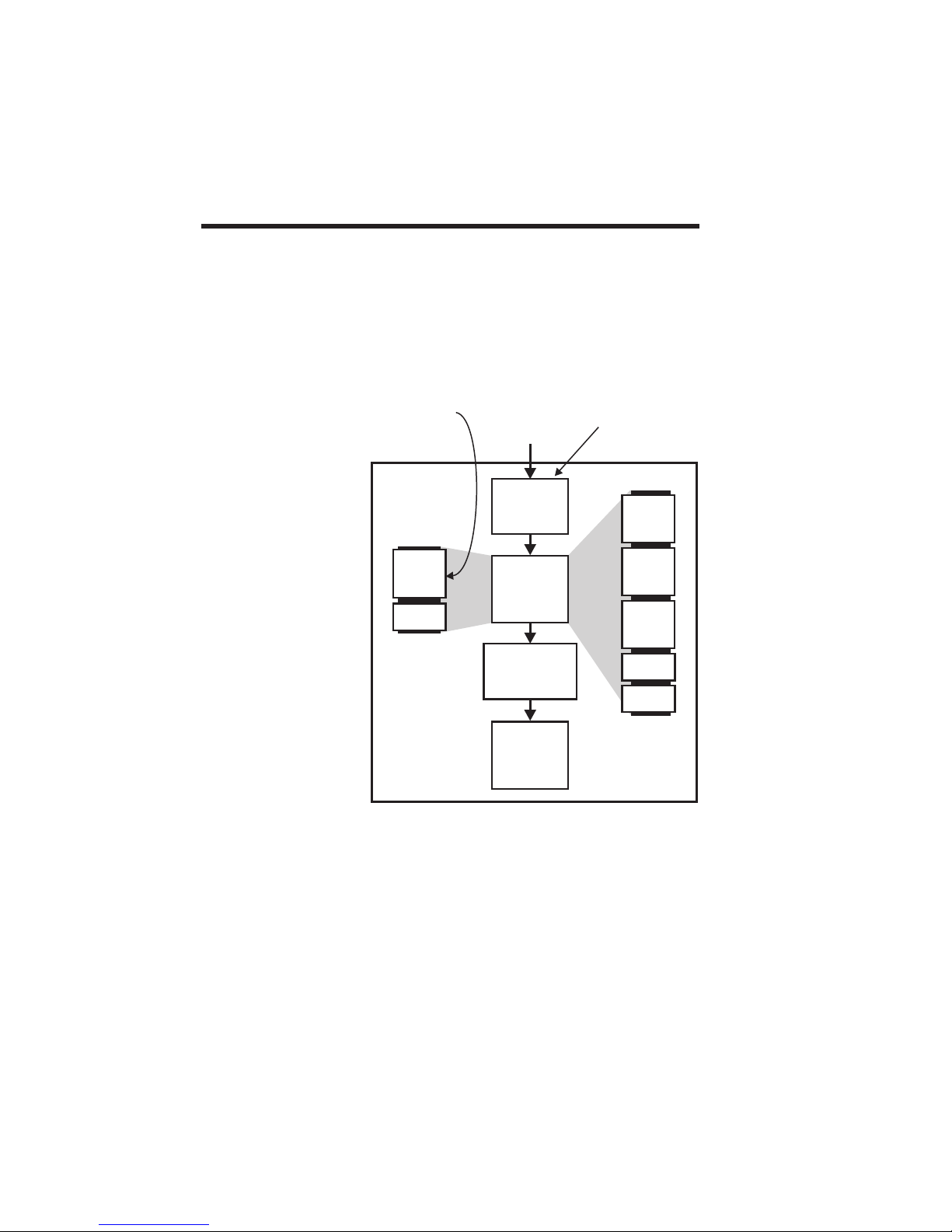
Figure 1-1 shows elements involved in image data
flow. Note that three Image Memory configurations
exist andthat Image Memory always contains com
pressed data. Ideally, hosts should send com
pressed data, which requires a compatible
compression algorithm. This can substantially re
duce the data transfer times of most image files.
-
-
-
Figure 1-1
Memory
Arrangements
Color Card
Printers Only
CARD PRINTER
Normal
Memory
Color
Buffer
Mono.
Buffer
Host Computer
:
Image Data
Compression
Algorithm
Image
Buffers
Image Data
Decompression
Algorithm
Print Head
Registers
Bypassed
when Host
Compressed
Extended
Memory
Yellow
Buffer
Magenta
buffer
Cyan
Buffer
Black
Buffer
Var ni sh
Buffer
1-12 980081-001 Rev. F
Monochrome printers have no color buffers. Color
printers without Expanded Memory have single
color and monochrome buffers, requiring a print
pass after each color download for yellow,
magenta, and cyan data, and as stated previously,
the same operation for monochrome when black
and varnish require different bit-maps. In contrast,
Extended Memory makes possible single
downloads containing commands that specify the
contents of all five buffers. All P310 and P420
Page 21

Printers have the equivalent of an Extended Mem
ory. For Max Secure Systems, which have no var
nish requirements, the varnish buffer supplies the
bit map for the White Card image.
-
-
Bit-Map
Compression
Algorithm
Characteristically, a bit-map compression algo
rithm flags data segments as either repeating or
non-repeating, specifies the bytesrepeated, and the
number of repeats. For these card printers, com
pression applies to byte-wide bit-map segments,
which the host sends with the PS, GS, Z, and vZ
commands. The PS and GScommands include pa
rameters specifying a buffer (YMCK). Monochrome
commands Z and vZ send associated bit-map data
to the black (K) and Varnish buffers, respectively.
All of thesecommands include parameters that spe
cify whether or not the command applies to compressed data. For recognition by the card printer,
compressed data must conform to the following
rules:
Rule 1. When high, themost significantbit (theflag
bit) of a two-byte sequence indicates that the second byte repeats. The remaining seven bits of the
first byte specify the number of repeats, allowing a
field-specification of from zero to 127 repeats.
Rule 2. Whenlow, the most significant bit of a data
sequence indicates that the remaining seven bits of
the byte specify the number of the following bytes
that represent non-repeatingimage data. However,
only from zero to 31 repeats can occur.
Rule 3. The first byte in the data field of any com
mand specifying a compressed bit-map must have
the compression flaghigh, even if a onemust be en
tered as the number of bytes repeated.
-
-
-
-
-
-
980081-001 Rev. F 1-13
Rule 4. No other algorithm can be used to com
press image data for this card printer.
Figure 1-2 includes examples of data strings
employing compression.
-
Page 22
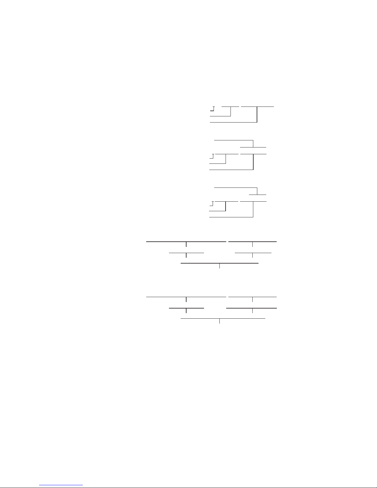
Figure 1-2
Bit-Map
Compression
0XXX XXXX
Data Compression Flag Off
No. of Non-Compressed Bytes
Non-Compressed Data
Mono. Panel 8-Dot Data Field
1XXX XXXX XXXX XXXX
Data Compression Flag Set
No. of Repeats (1~127)
Data Byte Repeated
Dye Sub. Panel 1-Dot Data Field
1XXX XXXX XXXX XXXX
Data Compression Flag Set
No. of Repeats (1~127)
Data Byte Repeated
Compression Example 1
0001 1111 0001 1111 0001 1111 0001 1111 0001 1111 0000 0011 0000 0011 0000 0011
1F Hex (5 repeats) 03 Hex (3 repeats)
85 1F 83 03
Compressed Data
1000 0101 0001 1111 1000 0011 0000 0011
---Bytes (0~31)---
Compression Example 2
0001 1111 0001 1111 0001 1111 0001 1111 0001 1111 0000 0100 0000 1011 0000 0011
1FHex(5repeats) 040B03Hex(0repeats)
85 1F 03 04 0B 03
1000 0101 0001 1111 0000 0011 0000 0100 0000 1011 0000 0011
Compressed Data
1-14 980081-001 Rev. F
Page 23
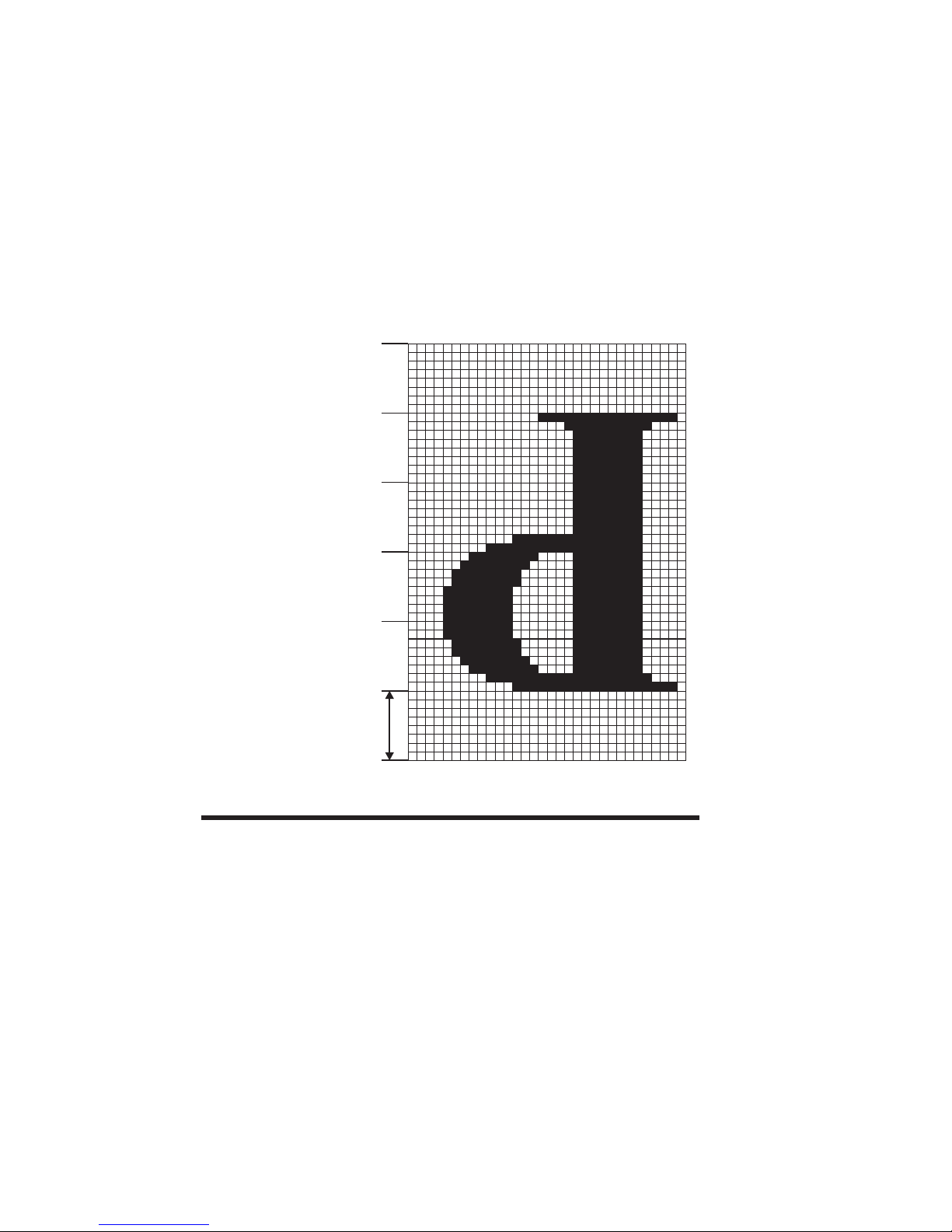
.
1
Non-Compressed
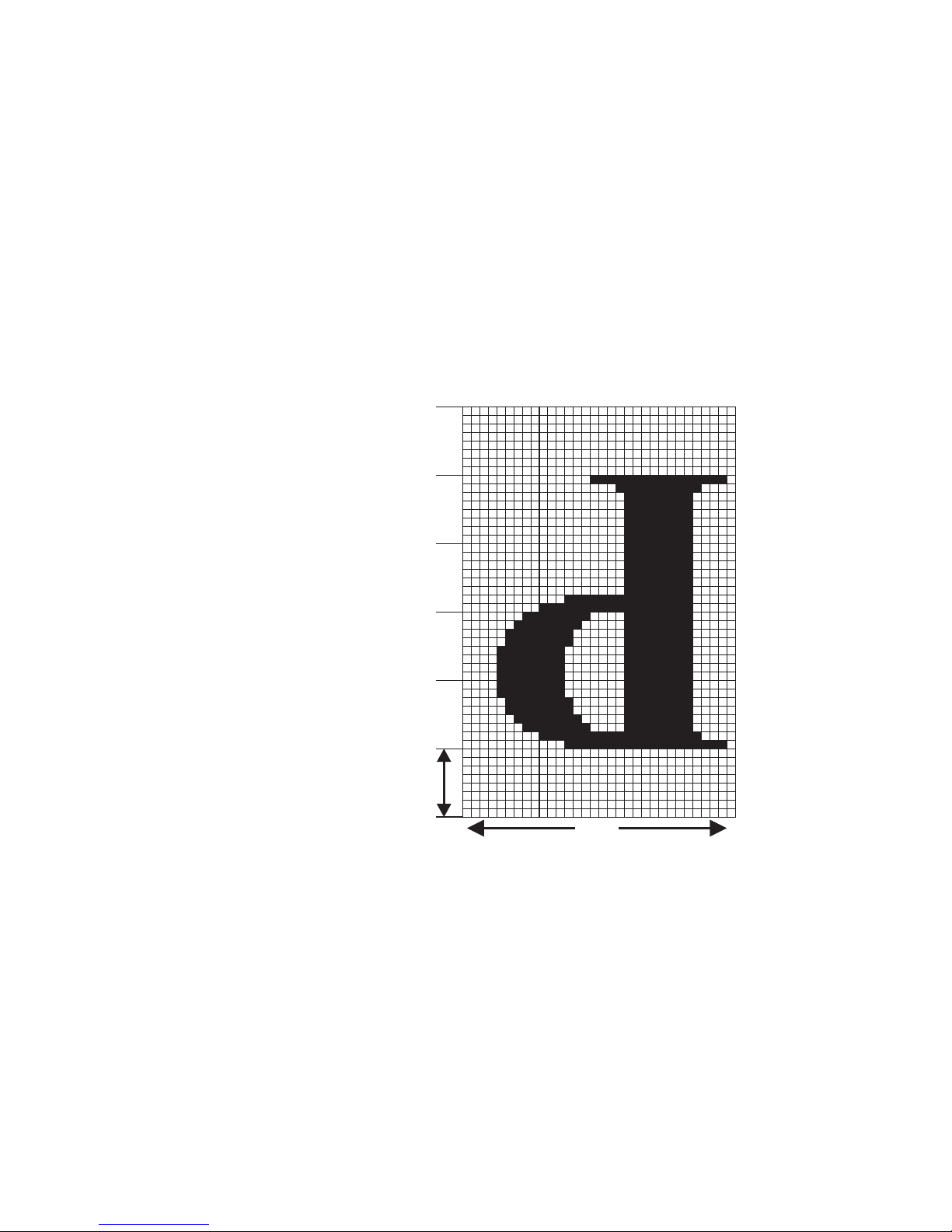
Figure 1-3
Bit-Map
Figure 1-3 shows how a bit-map relates to associ
ated non-compressed data. Figure 1-4 shows the
same bit-map in association withcompressed data
B 5A
1
00 00 00 00 00 00
00 00 00 00 00 00
00 00 00 00 00 00
00 00 00 00 00 00
00 03 F0 00 00 00
00 0F FC 00 00 00
00 1F FE 00 00 00
00 3F FF 00 00 00
00 3F FF 00 00 00
00 7F FF 80 00 00
00 7F FF 80 00 00
00 7F FF 80 00 00
00 FC 0F C0 00 00
00 F0 03 C0 00 00
00 E0 01 C0 00 00
00 C0 00 C0 01 00
00 C0 00 C0 01 00
00 C0 00 C0 01 00
00 C0 00 C0 03 00
00 FF FF FF FF 00
00 FF FF FF FF 00
00 FF FF FF FF 00
00 FF FF FF FF 00
00 FF FF FF FF 00
00 FF FF FF FF 00
00 FF FF FF FF 00
00 FF FF FF FF 00
00 C0 00 00 03 00
00 80 00 00 01 00
00 80 00 00 01 00
00 80 00 00 01 00
00 00 00 00 00 00
-
0D
980081-001 Rev. F 1-15
Byte
x axis
Page 24
1
Figure 1-4.
Compressed
Bit-Map
1B 5A
99 00 02
03 F0 84 00 02
0F FC 84 00 02
1F FE 84 00 02
3F FF 84 00 02
3F FF 84 00 3C
7F FF 80 00 00
00 7F FF 80 00 00
00 7F FF 80 00 00
00 FC 0F C0 00 00
00 F0 03 C0 00 00
00 E0 01 C0 00 00
00 C0 00 C0 01 00
00 C0 00 C0 01 00
00 C0 00 C0 01 00
00 C0 00 C0 03 00
00 84 FF 02 00
00 84 FF 02 00
00 84 FF 02 00
00 84 FF 02 00
00 84 FF 02 00
00 84 FF 02 00
00 84 FF 02 00
00 84 FF 18 00
00 C0 00 00 03 00
00 80 00 00 01 00
00 80 00 00 01 00
00 80 00 00 01 87
00
0D
Byte
Data-to Card
Mapping
Figure 1-5 shows a card consistent with the orienta
tion of a cardtraveling rightto leftin the card pathof
a printer. From this perspective,the data field of the
PS, GS, Z, and vZ commands first becomes a
memory-resident image in a designated image
buffer. TheImage Buffer,as shown, fills from top to
bottom and from right to left. Because the Image
Buffer has a last-in-first-out arrangement, card im
ages build from bottom totop and fromleft to right.
1-16 980081-001 Rev. F
-
-
Page 25
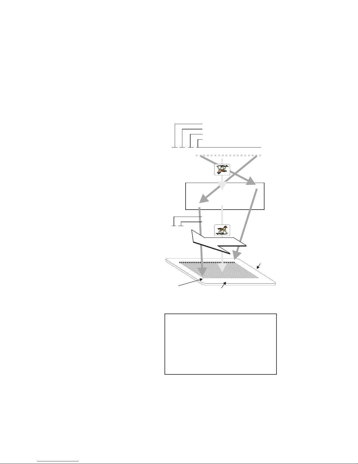
This suits the front-to-back loading of Print Head
Registers and the right-to-left card movement dur
ing print cycles. As noted in the figure, an object
mirrored in both axis in the data sent to the buffer
would print normally on the card.
-
Figure 1-5
Data Sent verses
Card Mapping
Download Buffer Data Command
Buffer Select (CMYK) Parameter
Compressed vs. Uncompressed Parameter
Data Downloaded (300dpi/11,8dpmm)
PS p1 p2 data.............................data
Last In
First Out
Image Buffer
Print Buffer Command
Buffer Select (CMYK) Parameter
IS p1
Print Direction
Card Size
3.375 x 2.125 in
85,7 x 53,9 mm
PartialImage
Origin
652 Lines Bytes by 1048 Lines (Max Secure Systems)
* Objects drawn with these commands have an upper-left origin.
MAXIMUM CARD IMAGING
624 Line Bytes by 1008 Lines (Standard Memory)
640 Line Bytes by 1024 Lines (Extended Memory)
ASSOCIATED COMMANDS
Monochrome
G
O
Z
P
L*
C*
D*
T
B
I
Overlay
IH
IV
vZ
vP
vL*
vC*
vD*
vT
vB
Color
PS
GS
IS
980081-001 Rev. F 1-17
Page 26

Color Data
Considerations
Color data always enters a color image buffer, ei
ther as yellow, magenta, cyan, or in the case of a
KsO ribbon, dye sublimationblack. Ifonly onecolor
image buffer exists, the command designates the
buffer differently according to the buffer specifica
tion parameter in the command. Note that the
specification for dye sublimation onlyapplies to im
ages produced using a dye sublimation black rib
bon. All data associated with these commands
represent five-bit-per-dot imaging.
Whether downloading data for a partial image (GS
command) or for a complete card image (PS com
mand) the data must match the associated card
area. For partial images(sometimes calledlogos be
cause of a typicalapplication) theGS command pa
rameters specify the area imaged. This assures
proper line breaks. Any either over- or under-flow
produces an error. Note that the previous figure
shows different full-card image areas for Standard,
Extended, and Max Secure memory. For proper
appearance, color images should not overprint
other card printing.
-
-
-
-
-
-
-
Max Secure
Monochrome Data
Considerations
P3xx~P600
Monochrome Data
Considerations
Max Secure printers have no need to print varnish.
However, the varnish buffer is used for monochrome data. Therefore, all data commands for
monochrome data require the“v” preface.A subsequent “I” command printsdata stored inthe varnish
buffer. Note that the IVcommand serves to indicate
the presence of a ribbon with varnish panels that
then get bypassed.
P-Series printers always download monochrome
data to a monochrome image buffer. Monochrome
data commands prefaced with a “v” designate the
varnish buffer. Commands without the “v” preface
designate the buffer used for resin printing. If only
one monochrome image buffer exists, the com
mand designates the buffer differently depending
on the associated data.
However, most color imaging does not need a
pre-established varnish buffer to apply the varnish
coating. If no varnish buffer is downloaded, the
printer defaults to theresin bufferfor theapplication
of varnish. This works for three reasons. First, color
1-18 980081-001 Rev. F
-
Page 27

ribbons have resin black followed by varnish pan
els, both limited to monochrome data. Second, the
primary use of varnish is to protect thedye sublima
tion imaging from ultraviolet radiation. Third, be
cause resin may need no varnish protection, an
inverted-resin bit-map can apply varnish.
-
-
-
The IV command has a parameter setting to pro
duce an inverted data print. In summary, leave the
resin buffer unchanged afterprinting resin.Then, is
sue an IV command for inverted data to print the
varnish. Note that full-coverage varnish,as required
for ultraviolet protection using dye-sublimation
black ribbons, requires only a buffer clear com
mand (F) followed by theinverted print command.
A watermark simulation can result by, in effect,
punching holes in the varnish image. A hologram
transfer from an associated ribbon occurs by
printing a varnish buffer that images the area of the
ribbon containing the hologram. Both of these images require data previously downloaded into the
Varnish buffer.
Monochrome graphic objects can download
into either the resin or varnish buffer. As with the
preceding, a “v” preface designates a buffer that
prints with the “IV” command, and commands
without the “v” preface designate a buffer that
prints with the “I” command. Commands exist for
downloads of the following graphic objects:
P/vP Write Dot
L/vL Write Line
C/vC Write Box
-
-
-
980081-001 Rev. F 1-19
D/vD Write Diagonal Line
T/vT Write Text
B/vB Write Bar-Code
Page 28

Rotational parameters (clockwise) exist for the fol
lowing:
D/vD 0, 90, or 180°
Center of Rotation lower-left
T/vT 90° Increments (0~270)
Center of Rotation lower-left or object center
B/vB 90° Increments (0~270)
Center of Rotation lower-left or object center
Monochrome bit-maps require entry of two
commands—first an initializing command (G) and
then the associated data command. The “G” com
mand specifies image placements associated with
the following commands:
O/vO Download Single Line
Z/vZ Download Multiple Lines
Figure 1-5 shows the relationshipbetween datasent
by “O” or “Z” commands and an area previously
established by a “G” command. The “G” command can also define data as single bits (i.e., image
dots).
With dots selected as the data mode in the “G”
command, data sent to the printer must, nevertheless, finish on an even byte boundary.When necessary, fill in zero bits to bytes that do not reach the
boundary specified in the “G” command.
-
-
Data is handled in bytes (0~255 decimal or hexa
decimal 00~FF) by the printer.
Bar Codes Bar codes vary in capacity, size, character sets, and
density. Several industries have adopted specific
coding and bar code formats. Verify that the se
lected bar code matches a code supported by the
scanning equipment.
All the bar codes supported by the card printers
have the data characters, 2 quiet zones, and a start
and stop character. The bar codes can include text
as part of the printed bar code. Some of the bar
codes include a printer-generated check digit (or
data check sum) character automatically or as an
option.
1-20 980081-001 Rev. F
-
-
Page 29
A command error condition occurs whenimage
data extends beyond the addressable range of the
image buffer. The bar code and text fields must re
main within the addressable area of the image
buffer. Each one of the bar codes, described in the
Command B and Appendix A, have a formula to
determine a bar code length.
Selecting a larger bar code width multiplier and a
higher ratio of the narrow to wide bars (and spaces
where applicable), improves the general readability
of a given bar code. Additionally, for a given bar
code, wider bars and spaces increase the depth of
field for improved performance with moving-beam
lasers and other non-contact scanning devices .
Control Commands The cardprinter canperform avariety ofprint, card,
ribbon, and headmovement andcontrol command
operations.
-
Print Controls
1. Intensity - Adjusts the amount of heat used to
transfer maximum intensity color or Monochrome
dot.
2. Contrast (Color Only) - Adjusts the minimum
amount of heatused to printdots at thelowest color
setting.
3. Image Positioning - Locates the printable im
age on the card.
4. Head - Raises the print head to move the card
and lowers it to print. Not normally required.
5. Print Test Cards
Card Movement
1. Print Ready position - Thecard movesto aposi
tion just prior to the card edge sensor.
2. Exit Card - The printer exits the card to the Ou
tput Hopper or tray. Printers with multiple stations,
exit the card to the next station.
980081-001 Rev. F 1-21
-
-
-
Page 30

3. Duplex - Flips the card over using the Card-Flip
Assembly, initiated by the ‘MF’ command.
4. Ready Smart Card - Positions a Smart Card
under the SmartCard Docking stationwith the con
tacts of a Smart Card chip engaged.
5. Encode Ready position - The card moves to a
position just prior to the magnetic encoding station
read/write head.
-
Ribbon
Card Handling
Process
1. Reset Ribbon - Setsthe ribbon panel to the first
panel (color - yellowpanel) orcycles thecontinuous
color Monochrome ribbon.
2. Select Panel - Resets, then selects a specific rib
bon panel.
The following outlines a recommended card handling sequence.
1. Smart Card Programming - Option
2. Magnetically Encode Card - Option
3. Print Card
For color printing:
Yellow
Magenta
Cyan
Black
Clear Varnish or Hologram Transfer
4. Duplex - Flip Card - Option
5. Print Card Backside - Option
For color printing:
Yellow
Magenta
Cyan
Black
Clear Veneer
Hologram Lamination
6. Eject Card
-
1-22 980081-001 Rev. F
Page 31

DO NOT print, veneer, or laminate over the mag
netic stripe or Smart Card contacts. This can impair
subsequent associated read and write operations
and must be controlled by the programming.
Batch Processing The “M” and “m” commands serve as command
linking operators. A string of linked commands may
execute one (1) time ormultiple times.The “[” char
acter acts as delimiter for linked commands in the
associated syntax.
-
-
Sample Card Figure 5-6shows aprinted card along withthe com-
Figure 1-6
Sample Monochrome
Card
For the complete “M” commandsyntax, and an ex
ample, see M/m in the Command Reference,
mands used.
Commands
¿
+RIB 4 Ribbon Type
¿
+C 3 Thermal Intensity
¿
F Clear Monochrome Buffer
B51260040241001TEST Write Bar Code
T51275400351Company Name, Incorporated Write Text
T200200010501FIRSTNAME WriteText
T200300010501LASTNAME WriteText
T200400010501ACCOUNT NUMBER Write Text
T65320710500Reversetext WriteText
L158097041 WriteLine¿
I Print Monochrome¿
¿
¿
¿
¿
¿
Descriptions
¿
-
980081-001 Rev. F 1-23
Page 32

Port Signals P3xx andP4xx printershave anoptional serialport.
Serial equipped printerscommunicate withthe host
over an RS-232C interface using ACK/NAK flow
control. Parallel ports are the standard. P500,
P600, and Max Secure card printers have no serial
option.
Card printers with Parallel Ports communicate with
the host using the following signal lines:
DATA (0~7) Eight bits of parallel data.
STROBE (Pin 1) A host signal that indicates stable data.
ACK/ (Pin 10) A printer signal that indicates data received. The
host drops the STROBE signal in response.
BUSY (Pin 11) A printer signal indicates an inability to accept
commands due to ongoing processing. P500 and
P600 card printers have two processors. A BUSY
response from one processor does not imply a
BUSY at the other processor.
READY (Pin 13) A printer signal that indicate its availability to
receive host commands.
PAPER ERROR (Pin 12)
Card printers report errors to the host by encoding the PAPER ERROR and ERROR lines (see Error Line Coding below).
ERROR/ (Pin 15) Card printers report errors to the host by encod-
ing the PAPER ERROR and ERROR lines (see Error Line Coding below).
INIT (Pin 14) Only used by P600 card printers, where a high (1)
directs commands to Module 1 (Master) and a
low (0) directs commands to Module 2 (Slave).
Error Line Coding
1-24 980081-001 Rev. F
Paper Error Error/ Description
01
00
11
10
Note: To clear an Error, Send: .↵ (1B 2E 0D Hex)
No Error
Syntax Error
Ribbon End/Empty Feeder
Mechanical Error
Page 33

COMMAND REFERENCE
This section contains descriptions of printer commands used to print,magnetically encode,position,
and control card movements. The following table
groups commands by function. Note printer applicability to avoid using commands that do not apply
to the targeted model(s).
980081-001 Rev. E 2-1
Page 34

Command List
DESCRIPTION
COMMAND
Setup Commands
Offset Start Print Position (X-axis)
+O
Offset Start Print Position (Y-axis)
+OY
Offset Overlaminate Patch
+OLP
Print Length (X-axis)
+EC
+LAYER
+OCL
Tests
Initialize Commands
Choose Number of Card Layers (Max3300)
Print Head Resistance
!R
Set Ribbon Color Sequence
!FF
Ribbon Type
+RIB
Set Black Speed
+BS
Adjust Thermal Transfer Intensity Level
+C
Adjust Overlay Application Intensity Level
+CV
Adjust Independent Color Intensity Level
+$L
Adjust Hologram Application Intensity
+CH
Adjust Independent Color Contrast Level
+$C
Offset (X-axis) Smart Card
+OS
Center Image Maps (P310)
SXY
Offset Contactless (Proximity Card)(P420)
Move Contactless (±1-Step)(P420)
MCL
Card Rejects for REJECTED BOX FULL Error (P420)
CRB
Hopper Selection for Rejected Cards (P420)
+RB
Print Test Card
A
Print Color Test Card
IM
Print Test Card
IMB
Clears Error Status Lines
.
Reset Printer
R
Clear Monochrome Image Buffers
F
Clear Color Bit-maps
$F
Clear Specified Bit Map (P310/P420)
$FP
P3xx Monochrome
P3xx/Color
P4xx Duplex Color
P500 Laminate
P600 Dual Print
Max Secure
PAGE
••••••2-10
••••••2-11
• 2-12
••••••2-13
• 2-14
••••••2-15
•••••2-22
•••••2-23
••••••2-30
••••••2-50
•••• 2-52
•••••2-57
•••• 2-61
•••••2-58
••••• 2-78
• 2-79
• 2-80
• 2-81
• 2-82
• 2-83
••••••2-33
•••••2-31
••••••2-32
••••••2-5
••••••2-6
••••••2-34
•••••2-53
• • • 2-54
2-2 980081-001 Rev. F
Page 35

DESCRIPTION
COMMAND
Reset Encoder
&R
Change Encoding Direction
&W
Change Encoder Track Write Density
&D
Custom Encoder Read Density
&CDER
Custom Encoder Write Density
&CDEW
Set Encoder Coercivity
&C
Serial Interface Rate (Serial I/O)
+B
Change Control Character (Serial I/O)
+X
Synchronize Film (P500 Overlaminate Only)
SF
Film Type (P500 Laminator)
TF
Set Temperature (P500 Laminator)
+TC
Set Lamination Configuration (P500)
+DLAMI
Set Lamination Speed
+VL
Reduce Color Print Speed (P310/P420/Max3300)
+VC
Reset Rejected Card Box to Zero (P420)
RCBC
Printer Query Commands
Check Printer Type/Version
V
Return Operational Parameter (Max3300)
!V
Retransmit Last Response (Serial I/O)
E
Check Command Initiator (Serial I/O)
!X
Check Card Presence - Encoder (Serial I/O)
&P
Check Due-for-Cleaning Set (P310/P420/Max3300)
%CLN
Image Data Download Commands
Initialize Monochrome Graphic
G
Load Single Line Graphic Dots Download
O/vO
Multiple Line of Graphic Dots Download
Z/vZ
Write Dot
P/vP
Write Line
L/vL
Write Box
C/vC
Write Diagonal Line
D/vD
Write Text
T/vT
P3xx Monochrome
P3xx/Color
P4xx Duplex Color
P500 Laminate
P600 Dual Print
Max Secure
PAGE
••••••2-63
••••••2-68
••••••2-69
••••••2-70
••••••2-72
••••••2-75
• • • • 2-84
• • • • 2-86
• 2-90
• 2-91
• • 2-92
• 2-93
• • 2-98
• • 2-99
•
2-10
0
••••••2-8
• 2-9
• • • • 2-85
• • • 2-87
• • • 2-88
• • • 2-89
••••••2-35
••••••2-36
••••••2-38
••••••2-40
••••••2-41
••••••2-42
••••••2-43
••••••2-44
980081-001 Rev. F 2-3
Page 36

DESCRIPTION
COMMAND
Write Bar Code
B/vB
Download Color Image Data
PS
Download Color Graphic
GS
Card Positioning Commands
Clear Media Path
MC
Input Card To Print Position
MI
Reverse Card to Print Position
MIB
Exit Card To Output (Hopper)
ME
Back Card Into Feeder
MB
Exit Loaded Card To Output
MO
Flip-over the card 180°
MF
Switch to White Card (Max3000)
MF
Eject Card with Magnetic Encoder Option
&T
Move Smart Card to Programming Station
MS
Move Card to Reject Box (P420)
MRB
Print Commands
Print Card Panel (YMC)
IS
Print Card Monochrome Panel
I
Print Varnish Overlay
IV
Print Hologram Overlay
IH
Print Multiple Cards “N” times
J
Magnetic Stripe Encoder Commands
Encode Single Data Track
&E
Buffer Track Data
&B
Encode All Data Tracks
&E*
Read Single Track Data
&L
Miscellaneous Commands
Multiple Command Strings
M/m
Move Print Head Up
!M
Move Print Head Down
!D
Self Adjust (P310/420/Max3300)
!SA
CLNCARD
Set Cleaning Card Sequence (P310/P420/Max3300)
Start Cleaning Card Sequence (P310/P420/Max3300)
CLEAN
P3xx Monochrome
P3xx/Color
P4xx Duplex Color
P500 Laminate
P600 Dual Print
Max Secure
PAGE
••••••2-39
•••••2-55
•••••2-56
••••• 2-7
••••• 2-17
••••• 2-18
••••••2-19
••••• 2-20
••••••2-21
• • • • 2-62
• 2-62
••••• 2-74
••••• 2-76
• 2-77
•••••2-59
••••••2-48
•••••2-51
•••• 2-60
••••• 2-49
••••••2-64
••••••2-65
••••••2-66
••••••2-67
••••••2-16
••••••2-25
••••••2-26
• • • 2-27
• • • 2-28
• • • 2-29
2-4 980081-001 Rev. E
Page 37

. Command - Clear Error Status
Description Clears the Paper Error (Paper Fault) and Error
(Fault) printer return signal status lines. Note that
this command does not execute when sent via the
Driver. Send the command directly to the printer
port.
P3xx M
P3xx C
P4xx
P500
P600
•
•
Max
•
•
•
Syntax
.↵
Parameters None
980081-001 Rev. F 2-5
Page 38

P3xx C
P4xx
P500
P600
• P3xx M
•
Max
•
•
•
•
R Command - Reset
Description Reinitializes printer—also the Max3000 Printer
module.
Syntax
Syntax (Max3000
Laminator)
Parameters None
To reset another Max3000 module, direct the com
mand to the Laminator/Die Cutter Station, or En
coder.
R↵
#11 R↵
-
-
2-6 980081-001 Rev. F
Page 39

MC Command - Clear Media Path
Description Sends any card in the Media Path of the printer to
the Output Tray.
Note: A Ribbon Errorcan leavea cardin theprinter.
If issued at Power-On,this command assures aclear
media path for subsequent operations.
Syntax MC↵
Parameters None
P3xx M
P3xx C
P4xx
P500
P600
•
•
Max
•
•
•
980081-001 Rev. F 2-7
Page 40

P3xx C
P4xx
P500
P600
• P3xx M
•
Max
•
•
•
•
V Command - Check Printer Type/Version
Description This command serves to check the model (and op
tions) of a printer. Serial port connected printers re
spond with a model numberand firmware version.
Parallel port connected printers respond with
NACK when the ‘V’ command parameter received
does not match the configuration. A matching
printer parameter code produces anACK response.
Note that parallel-connected color printers do not
report firmware and model. For this information,
use the “A” command.
Syntax V{p1}↵
p1 = Optional Configuration Parameter (for Parallel I/O)
P3xx, P400, P500, and P600 Printers
SN<7000 Monochrome printers only.
None
P3xxCF
10
Magnetic Encoder Installed
12
Smart-Card Docking Installed
13
P400CF
14
Extended Memory Option Installed
20
Magnetic Encoder with expanded encoder
30
command set. (Serial numbers > 5000)
Monochrome printer with Parallel or Serial Port
50
(Serial numbers >7000).
P500 Printer
70
P600 Printer
80
P310 Printer
100
-
-
2-8 980081-001 Rev. F
Max Secure Printers
Encoder and Laminator
80
Laminator only
81
Encoder only
82
Printer
83
Max3300
85
Page 41

P3xx M
!V Command - Return Operational Parameter
Description Returns value for a selected parameter.
Note that this command only applies to Max3300
Printer and Laminator Modules.
Syntax !V{p1}↵
p1 = Requested Parameter
Where for Printer Module:
None = Return Black Printing Parameters
0 = Return Black Printing Parameters
1 = Return X Offset
2 = Return Y Offset
3 = Return Print Head Resistance
4 = Return X offset for Clear Card Material
5 = (Not Used)
6 = Card Layers Set (0 for 2; 1 for 3)
7 = Return First Layer Cut Offset
8 = Return Third Layer Cut Offset
For Laminator Module:
0 = Bottom Roller Temp. (Layer Configuration
Dependant)
1 = Die Cutter Offset (!CM 08)
2 = Lamination Speed (Layer Configuration
Dependant)
3 = Good Lamination Counter
4 = Error Counter
5 = Movement Speed
6 = Idle Time in Standby Mode
7 = Standby Mode Temp.
8 = Layer Configuration (0 for 2; 1 for 3)
9 = Top Roller Temp. Setting (Layer Configuration
Dependant)
P3xx C
P4xx
P500
P600
Max
•
980081-001 Rev. F 2-9
Page 42

P3xx C
P4xx
P500
P600
• P3xx M
•
Max
•
•
•
•
+O Command - Print Offset X-axis
Description Alters the horizontal (X-axis) start print offset point,
in dots.
Syntax +O p1↵
Parameters p1 = Horizontal (X-axis) start print offset, in dots:
Where:
10 = Default (Std Memory)
10 = Default (Max3000)
8 = Default (Expanded Memory)
0~20 =Range (1~20 for Max Secure)
2-10 980081-001 Rev. F
Page 43

+OY Command - Print Offset Y-axis
Description Offsets the vertical (Y-axis) start print location in
dots.
Syntax +OY p1↵
Parameters p1 = Vertical (Y-axis) offset, in dots
Where:
15 = Default (Standard Memory)
6 = Default (Extended Memory)
6 = Default (Max)
P3xx C
P4xx
P500
P600
• P3xx M
•
Max
•
•
•
•
980081-001 Rev. F 2-11
Page 44

P3xx M
P3xx C
P4xx
P500
P600
Max
•
+OLP Command - Offset Overlaminate Patch
Description Specifies the relationship between card positions
and Ribbon Sync Markersused to placeLamination
Patches on cards.
Note that exceptfor the first patch, thefirmware can
use Ribbon Sync Marker sensing in concert with
Flag Sensor Increment sensing todetermine Ribbon
Advance Step requirements for patch applications.
However, a Ribbon Initialization leaves the firm
ware without an associated history for Ribbon Step
requirements. Because ofthis, thefirmware needs a
beginning step valuefor use onlyto position therib
bon after an Initialization.
Note: This command only applies to P500
Laminator Stations and ribbons with Sync.
Markers.
-
-
Syntax
+OLPp1p2p3¿
Parameters p1 = Card Offset Count from Ribbon Sync. Marker sense to the
point p2 takes effect. Only used to synchronize lamina-
tion patches that follow Initializations
p2 = Offset between where patch applications start
p3 = Count where patch applications end
Default Settings
+OLP11014090¿
2-12 980081-001 Rev. F
Page 45

+EC Command - End of Print
Description Specifies a point, beyond which, no card printing
occurs. Print stations with associated Extended
Memory installedhave storage for 1024 lines of im
aging, which exceeds the x-axis image area on the
cards.
The parameter for End of Print causes the print
head to raise atthe end-of-card point,not theend of
data. If left down beyond the end of card, the print
head can shear the ribbon as the print head
abruptly drops below the surface of the card. Note
that higher values of p1 result in shortened line
counts.
Syntax +ECp1↵
Parameters p1 = line count for end-of-print
Where:
8 = default (standard)
0 = default (Max3000)
0~24=range
P3xx C
P4xx
P500
P600
• P3xx M
•
Max
•
•
•
•
-
Example The followingexample sets theEnd ofPrint to8 (the
default value).
+EC8↵
980081-001 Rev. F 2-13
Page 46

P3xx M
P3xx C
P4xx
P500
P600
Max
•
+LAYER Command - Choose Number of Card
Layers
Description Specifies creation of two- or three-layer cards
Note that this command only applies to Max3300
Systems. When sent, both the Printer and
Laminator receive this command.
Syntax +LAYERp1↵
Parameters p1 = Number of Layers
Where:
0 = Two Layers
1 = Three Layers
2-14 980081-001 Rev. F
Page 47

!R Command - Print Head Resistance
P3xx C
P4xx
P500
P600
• P3xx M
•
Max
•
•
•
•
Description Enters manufacture’s average resistance that ap
pears on the print headlabel. Note thatreplacement
to a print head with 10-micron glass can produce
faint printing if not offset (typically from between
180 and 225 ohms). An offset that optimizes print
quality should be found.
Note: This setting interacts with the following com
mands:
+C Thermal Transfer Intensity
+$L Color Intensity
+$C Color Contrast
Syntax !Rp1↵
Parameters p1 = Resistance
Where:
p1 range = 1400~2350
Example In the following example, 1567 ohms is entered
based on the print head label.
!R1567↵
-
-
980081-001 Rev. F 2-15
Page 48

P3xx C
P4xx
P500
P600
• P3xx M
•
Max
•
•
•
•
M/m Commands - Multiple Command
Description Groups and repeats a string of commands “N”
times. “M” differs from “m” only regarding the re
sponse to errors. Errors encountered during com
mands linked by “m” commands abort any
remaining commands, while M-linked commands
resume after error removal.
Note that Max3000s perform best with this kind of
command linking for the print-related commands
(see Appendix E).
-
-
Syntax
M p1c1[c2[c3...[cn↵
Parameters p1 = Number of times to repeat following command string.
1~Cn =
C
Series of linked commands repeated p1 times. Note the
square bracket ([) delimiters.
Example This example shows an “M” command used to
group and repeat four commands.
M
3MI[ !D[ !M[MO↵
The “M” command groups a command string. A
card loads to the print ready position with the “MI”
command. “!D” lowers the print head; “!M” raises
the print head, and “MO” sends the card tothe out
put tray.
The “M” command specifiesthree repeatsof thisse
quence. If an error occurs (e.g., the input hopper
runs out of cards) a command sequence linked by
the “M” command terminates. In contrast, after er
ror correction and an associated pressing of the
Panel Button, a command sequence linked by the
“m” command resumes.
-
-
-
2-16 980081-001 Rev. F
Page 49

MI Command - Input Card To Print
Description Moves a card from the Card Input Hopper to the
Print Ready position.
For P600:
Moves card to the PrintReady position ofModule 1.
Syntax MI{p1}↵
Parameters p1 = none (Moves card to first Station)
p1 = 1 (Moves card to second station—P500 only)
P3xx C
P4xx
P500
P600
• P3xx M
•
Max
•
•
•
•
980081-001 Rev. F 2-17
Page 50

P3xx C
P4xx
P500
P600
• P3xx M
•
Max
•
•
•
•
MIB Command - Reverse Card To Card Feeder
Description For P300/P400:
Moves a card from beyondthe print positionback to
the Print Ready position.
For P500/P600:
Sent to Module 1, returns a card from beyond the
Print Ready position of Module 1 (not yet in Card
Flip of Module 2) to the Print Ready position of
Module 1.
Sent to Module2, returns a card toLaminate Ready
position from beyond Laminator of Module 2.
Syntax MIB↵
Parameters None
2-18 980081-001 Rev. F
Page 51

ME Command - Exit Card To Output Tray
Description For P300,P310 and P400,moves and exits a single
card from any position to the output tray.
For P500 and P600, moves and exits a single card
from any position except the Feeder to the Output
Tray.
Sent to Module 1,ejects a cardanywhere inthe card
Module.
Sent to Module2, ejects any card presentin Module
2. If no card is present, a Ribbon End or Card-Feed
error occurs.
Syntax ME{p1}↵
Parameters p1 = Number of cards to pass through printer.
P3xx M
P3xx C
P4xx
P500
P600
•
•
Max
•
•
•
980081-001 Rev. F 2-19
Page 52

P3xx C
P4xx
P500
P600
• P3xx M
•
Max
•
•
•
•
MB Command - Return Card To Card Feeder
Description Moves the card in the reverse direction and returns
the card to the card feed point (just inside the card
printer) from any position between the card feeder
and the output tray.
Sent to Module 2 of P500 and P600:
Returns a card in Module 2 to the Module 1 exit
point.
Syntax MB↵
Parameters None
2-20 980081-001 Rev. F
Page 53

MO Command - Exit Card To Output Tray
Description For P3xx and P400:
Moves and exits a single card from any position
except the Input Hopper to the output tray.
For P500:
Sent to Module 1, ejects a card from anywhere in
printer except the Input Hopperto the OutputTray.
Sent to Module 2, ejects a card in Module 2 to the
Output Tray. If no card is present, printer responds
ACK.
For P600:
Sent to Module 1,moves cardto Module2 fromany
position in Module 1, except the Input Hopper.
Sent to Module 2, moves card to Output Tray from
any position in Module 2. If no card is present,
printer responds ACK.
For Max:
Sent before an MF command, sends Clear Card to
the Card Assembly Station. Sent after an MF command, sends a White Card to the Card Assembly
Station, and if needed, sends the assembled cards
to the Laminator and Die Cutter module.
P3xx C
P4xx
P500
P600
• P3xx M
•
Max
•
•
•
•
Syntax MO↵
Parameters None
980081-001 Rev. F 2-21
Page 54

P3xx M
P3xx C
P4xx
P500
P600
•
Max
•
•
•
•
!FF Command - Set Ribbon Sequence
Description Resets and moves the ribbon to a selected panel.
The printer firstaligns onthe Cyan (andBlack) pan
els and then counts ribbon panel positions from the
Yellow “0" panel.
Syntax !FFp1↵
Parameters p1 = Panel detection number where:
p1 = 0 = Move ribbon to Sync Position, as follows:
Ribbon Sync Position
YMC Yellow Panel
YMCKr Yellow Panel
YMCKrO Yellow Panel
YMCKrOKr Yellow Panel
KsO Mid Overlay
KrO Mid Overlay
p1 =1 = Move to next transparent panel, unless already there
p1 =2 = Move to next non-transparent panel, unless already there
p1 = 3 = Move to beginning of Black (for YMCKrO ribbons only)
-
2-22 980081-001 Rev. F
Page 55

+RIB Command - Set Ribbon Type
Description Sets printer operation for either a Standard or one
of the nonstandard ribbons, as follows:
Standard Ribbons:
·
Kr (Monochrome—except P310 and Max3300)
YMCKrO
KsO
KrO
nonstandard Ribbons:
·
YMCKrOKr
YMC
YMCKr
YMCKrKr
YMCKr_Kr
Note: Parameter settings associated with this command establish the ribbon positioning that occurs
following a long press of the Panel Button. P310s
synchronize ribbons automatically after an unlatch
and latch of the Print Head, but require a P1 setting
of 4 toavoid attempted ribbon synchronization with
monochrome ribbons installed. Without this set-
ting, some ribbon wasteoccurs inan attemptedsynchronization.
P3xx M
P3xx C
P4xx
P500
P600
•
Max
•
•
•
•
Syntax +RIBp1↵
Parameters p
980081-001 Rev. F 2-23
= Ribbon Type
1
Where:
0 = Standard Ribbon
4 = Monochrome Ribbon (P310/P420/Max3300 only)
10 = 6-Panel Ribbon (YMCKrOKr)
11 = 3-Panel Ribbon (YMC)
13 = 4-Panel Ribbon (YMCKr)
21 = 5-Panel Ribbon w/spaced Kr (YMCKr_Kr)
Page 56

P3xx M
P3xx C
P4xx
P500
P600
•
Max
•
•
•
•
+RIB Command - Set Ribbon Type Continued)
Note: Card imaging using the YMCKOK ribbon re
quires the following command sequence:
IS 0 Image Yellow
IS 1 Image Magenta
IS 2 Image Cyan
I Image Black & Return (YMCKOK only)
IV 10 Image Varnish and Return
I 20 Image Black and Return
MO Eject Card
-
2-24 980081-001 Rev. F
Page 57

!M Command - Move Print Head Up
Description Moves the Print Head assembly up from the card
(and platen roller).
Syntax !M↵
Parameters None
P3xx C
P4xx
P500
P600
• P3xx M
•
Max
•
•
•
•
980081-001 Rev. F 2-25
Page 58

P3xx C
P4xx
P500
P600
• P3xx M
•
Max
•
•
•
•
!D Command - Move Print Head Down
Description Moves the Print Head assembly down to the card
(and platen roller).
Syntax !D↵
Parameters None
2-26 980081-001 Rev. F
Page 59

!SA Command - Self Adjust
Initiates a printer self-adjust sequence.
P3xx M
P3xx C
P4xx
P500
P600
•
Max
•
•
Note that this command requires the prior installa
tion of a 5-panel ribbon and works best with 10-mil
cards. Successful completion results in adjustment
of all sensors and voltages, confirmed by no errors
indicated.
Note that this command only applies to P310,
P420, and Max3300 printers.
Syntax !SA↵
Parameters None
-
980081-001 Rev. F 2-27
Page 60

P3xx M
P3xx C
P4xx
P500
P600
•
Max
•
•
CLNCARD Command - Establish Cleaning Card
Sequence
Allows settings for a time-to-clean alert and the cy
cling of cleaning card in card path.
Note that this command only applies to P310,
P420, and Max3300 printers.
Syntax CLNCARDp1p2↵
Parameters p1 = Ribbon Panel Count to Cleaning Notification (Default =
5000)
p2 = Number of Cleaning Card Passes Through Printer
(Default = 5)
-
2-28 980081-001 Rev. F
Page 61

P3xx M
P3xx C
P4xx
P500
P600
•
•
CLEAN Command - Start Cleaning Card Sequence
This command requires the prior removal of any
ribbon and a manual feed of a Cleaning Card. The
following occurs:
Raise Print Head
·
Feed a card to a position under Print Head
·
Lower Print Head
·
Move card back and forth the number of times
·
specified by CLNCARD Command.
Raise Print Head
·
Exit card
·
Note that this command only applies to P310,
P420, and Max3300 printers.
Syntax CLEAN↵
Parameters None
Max
•
980081-001 Rev. F 2-29
Page 62

P3xx C
P4xx
P500
P600
• P3xx M
•
Max
•
•
•
•
+BS Command - Set Black Speed
Description Optimizes Resin printing for either quality or print
speed.
Syntax +BSp1↵
Parameters p1 = Speed
Where:
0 = High Speed Printing
1 = High Quality Printing
2-30 980081-001 Rev. F
Page 63

IM Command - Print Color Test Card
Description Prints a card with a color test pattern.
Syntax IM↵
Parameters None
Figure 2-1
Color Test Card
P3xx M
P3xx C
P4xx
P500
P600
•
Max
•
•
•
•
980081-001 Rev. F 2-31
Page 64

P3xx C
P4xx
P500
P600
• P3xx M
•
Max
•
•
•
•
IMB Command - Print Gray Test Card
Description Prints anall graycard. Typicallythis card serves asa
basis for Print Head adjustments. Note that a black
ribbon is required (PVC-L BLK preferred—Part
Number 800015-001).
Syntax IMB↵
Parameters None
Figure 2-2
Print Black Test Card
2-32 980081-001 Rev. F
Page 65

A Command - Print Test Card
Description Prints a standard test card with printer parameters,
version number, and testpattern. Max systems print
two cards—one for the Printer the other for the
Laminator (if connected).
Syntax A{p1}↵
Parameters p1 = Test Card
Where:
None = Standard Test Card(s) (Includes a Test
nected)
1 = Printer Test Card
2 = Magnetic Encoder Test Card
3 = Lamination Test Card
Figure 2-3
Standard
Monochrome Test
Card
P3xx C
P4xx
• P3xx M
•
•
Card for each Max3000 Module con
P500
•
P600
•
-
Max
•
Figure 2-4
Standard Color Test
Card
Figure 2-5
Max Printer and
Laminator Card Pair
980081-001 Rev. F 2-33
Page 66

P3xx C
P4xx
P500
P600
• P3xx M
•
Max
•
•
•
•
F/vF Command - Clear Monochrome Image Buffers
Description Clears Monochrome image buffers of bit-maps and
printable data (lines, text, bar codes, etc.).
Syntax F↵
Parameters None
2-34 980081-001 Rev. F
Page 67

P3xx C
P4xx
• P3xx M
•
•
G/vG Command - Initialize Monochrome Graphic
(B/W)
Description Initializes Monochrome graphic area using height,
width and position.
Syntax G p1 p2 p3 p4 p5 p6↵
Parameters p1 = Horizontal (X-axis) start position (X) in dots.
p2 = Vertical (Y-axis) start position (Y) in dots.
p3 = Download Mode for Graphic (Bit-map):
When using bytes, the byte count must be rounded up
ward to the next nearest whole byte.
Example:
25 dots = 3 bytes + 1 dot = 4 bytes
Value Data Description
0 Byte
1 Byte
2 Byte
3 Byte
10 Dot
11 Dot
12 Dot
13 Dot
Standard
Standard with Checksum
Compressed
Compressed with Checksum
Standard
Standard with Checksum
Compressed
Compressed with Checksum
P500
•
P600
•
-
Max
•
p4= Vertical (Y-axis) height of graphic in bytes.
Round up the number of bytes loading in multiples of 8
bits (i.e. Monochrome dots).
p5 = Horizontal (X-axis) width of graphic in dots (i.e. horizon
tal lines).
p6 = Graphic Mode:
Value Description
980081-001 Rev. F 2-35
Reverse Bit-map - Clear print area
0
and load reverse bit-map image
Standard Bit-map - Clear print area
1
and load bit-map image
Merge Bit-map - Overwrite
background bit-map image with
2
printable dot locations leaving
non-printing dot locations alone.
-
Page 68

P3xx C
P4xx
P500
P600
• P3xx M
•
Max
•
•
•
•
O/vO Commands - Load Single Line Bit-map
(Mono.)
Description Loads a single line of Monochrome bit-map data
into a monochrome image buffer. The printer uses
the proceeding “G” command to specify and con
trol the line bit-map placement. An “O” command
specifies a Monochrome Bufferused forResin print
ing, and a vO command specifies a Monochrome
Buffer used for Varnish printing.
Syntax Odata{CHECKSUM}↵
vOdata{CHECKSUM}↵
-
-
Note: NO space
(20 Hex.) exists between the “O”
and the “data.”
Parameters data = Uncompressed or compressed Monochrome bit-map
data. Data length should match the line length as specified in the proceeding “G” command.
See Chapter 1 for the relationship of Monochrome
Bit-maps to data.
CHECKSUM = Single byte of XOR data generated from image data.
Example Proceeding Command is:
G20020002151↵
(This “G” command specifies 15 lines of 2-byte
bit-map data)
Remember, any chance control characters that ap
pear among the data require a preceding open
bracket ([) character.Control characters includeEs
cape (1B hex), Return (OD hex), and the Open
Bracket (5B hex).
-
-
2-36 980081-001 Rev. F
Page 69

O/vO Commands - Load Single Line Bit-map (Con
tinued)
The 15 “O” command lines immediately follow the
“G” command as:
“OdataLine1↵
“OdataLine2↵
“OdataLine3↵
etc.
-
Figure 2-6
Line by Line
Image Object &
Hexadecimal Code
1Byte
EscO
1B 4F 00 00 0D
1B 4F 00 00 0D
1B 4F 00 00 0D
1B 4F 00 00 0D
1B 4F 03 F0 OD
1B 4F 0F FC 0D
1B 4F 1F FE 0D
1B 4F 3F FF 0D
1B 4F 3F FF 0D
1B 4F 7F FF 0D
1B 4F 7F FF 0D
1B 4F 7F FF 0D
1B 4F FC 0F 0D
1B 4F F0 03 0D
1B 4F E0 01 0D
Data
CR
980081-001 Rev. F 2-37
Page 70

P3xx C
P4xx
P500
P600
• P3xx M
•
Max
•
•
•
•
Z/vZ Commands - Load Bit-map (Monochrome)
Description Loads a monochrome bit-map into a monochrome
image buffer. The printer uses the proceeding “G”
command to specify and control the bit-map place
ment.
The Z command places thebit-map in a buffer used
for Resin printing, and the vZ command places the
bit-map in a buffer used for Varnish printing.
Syntax Zdata{CHECKSUM}↵
vZdata{CHECKSUM}↵
-
Note: NO space
(20 Hex.) exists between the
“Z/vZ” and the “data.”
Parameters data = Uncompressed or compressed Monochrome bit-map
data. The bit-map data must match the size and dimension specified in the proceeding “G” command.
See Section 1 for the relationship on how monochrome
bit-maps relate to data.
CHECKSUM =
Single byte of XOR data generated
from the image data.
Remember, any chance control characters that ap
pear among the data require a preceding open
bracket ([) character.Control characters includeEs
cape (1B hex), Return (OD hex), and the Open
Bracket (5B hex).
-
-
2-38 980081-001 Rev. F
Page 71

Z/vZ Commands - Load Bit-map (Continued)
Example The following command and figure shows a “G”
command with an associated “Z” command con
taining data for the image buffer.
G20020002151↵
Zdata↵
-
Figure 2-7
Image Object &
Hexadecimal Code
1Byte
1B 5A
00 00
00 00
00 00
00 00
03 F0
0F FC
1F FE
3F FF
3F FF
7F FF
7F FF
7F FF
FC 0F
F0 03
E0 01
OD
EscZ
Data
CR
980081-001 Rev. F 2-39
Page 72

P3xx C
P4xx
P500
P600
• P3xx M
•
Max
•
•
•
•
P/vP Commands - Write Dot (Monochrome)
Description Writes a single monochrome dot to a monochrome
image buffer. The “P”command writesto thebuffer
used for Resin printing. The vP command writes to
a buffer used for Varnish printing.
Syntax P p1 p2 p3↵
Parameters p1 = Horizontal (X-axis) start position (X) in dots.
p2 = Vertical (Y-axis) start position (Y) in dots.
p3 = Graphic Mode:
Value Description
Reverse Bit-map - Clear print area
0
and load reverse bit-map image
Standard Bit-map - Clear print area
1
and load bit-map image
Merge Bit-map - Overwrite
background bit-map image with
2
printable dot locations leaving
non-printing dot locations alone.
2-40 980081-001 Rev. F
Page 73

L/vL Command - Write Line (Monochrome)
P3xx C
P4xx
P500
P600
• P3xx M
•
Max
•
•
•
•
Description Writes a Monochrome graphic line using parame
ters to specify origin, height, and width. The result
ing line overwrites any existing graphics data. The
“L”command writes to the buffer used for Resin
printing. The “vL” command writes to a buffer used
for Varnish printing.
Syntax
L p1 p2 p3 p4 p5↵
Parameters p1 = Horizontal (X-axis) start position (X) in dots.
p2 = Vertical (Y-axis) start position (Y) in dots.
p3 = Horizontal (X-axis) width of graphic in dots (i.e. horizontal
lines).
p4 = Vertical (Y-axis) height of graphic in dots.
p5 = Graphic Mode
Figure 2-8
Line /Rectangle
Value Description
0
Reverse Bit-map - Clear print area and load
0
reverse bit-map image
Standard Bit-map - Clear print area and load
1
bit-map image
Merge Bit-map - Overwrite background
bit-map image with printable dot locations
2
leaving non-printing dot locations alone.
LINES
Image Positioning
-
-
980081-001 Rev. F 2-41
D
O
T
S
Line Image Origin
Page 74

P3xx C
P4xx
P500
P600
• P3xx M
•
Max
•
•
•
•
C/vC Command - Write Box (Monochrome)
Description Writes a hollow-box rectangle graphic to a mono
chrome image buffer by defining the height, width,
line thickness (width) andorigin. The“C”command
writes to the buffer used for Resin printing. The
“vC” command writes to a buffer used for Varnish
printing.
Syntax
C p1 p2 p3 p4 p5 p6↵
vC p1 p2 p3 p4 p5 p6↵
Parameters p1 = Horizontal (X-axis) start position in dots.
p2 = Vertical (Y-axis) start position in dots.
p3 = Horizontal (X-axis) width of graphic line in dots (i.e. hori
zontal lines).
p4 = Vertical (Y-axis) height of graphic line in dots.
p5 = Thickness/width of diagonal graphic line in dots.
p6 = Graphic Mode
Value Description
Figure 2-9
Reverse Bit-map - Clear print area and load
0
reverse bit-map image
Standard Bit-map - Clear print area and
1
load bit-map image
Merge Bit-map - Overwrite background
bit-map image with printable dot locations
2
leaving non-printing dot locations alone.
0
LINES
Hollow Box
Image Positioning
D
O
T
S
-
-
P5
2-42 980081-001 Rev. F
Hollow Box
Image Origin
Page 75

P3xx C
P4xx
• P3xx M
•
•
D/vD Commands - Write Diagonal (Monochrome)
P500
•
P600
•
Max
•
Description Write a monochrome diagonal line graphic by de
fining the total height, total width, line thickness
(width) and position in the Monochrome image
buffer. The “D” command writes to the Resin
buffer, and the “vD” command writes to the Var
nish buffer. The actual imageplaced is arectangle.
Syntax Dp1 p2 p3 p4 p5 p6 p7↵
Parameters p1 = Horizontal (X-axis) start position, in dots.
p2 = Vertical (Y-axis) start position, in dots.
p3 = Horizontal (X-axis) width of graphic, in dots.
p4 = Vertical (Y-axis) height of graphic, in dots.
p5 = Thickness/width of the line, in dots.
p6 = Rotation & Origin:
Value Description Origin
1 90 degrees Lower Left
2 180 degrees Lower Left
p7 = Graphic Mode:
Value Description
Reverse Bit-map - Clear print area and load
0
reverse bit-map image
Standard Bit-map - Clear print area and
1
load bit-map image
Merge Bit-map - Overwrite background
bit-map image with printable dot locations
2
leaving non-printing dot locations alone.
-
-
Diagonal Line Values
980081-001 Rev. F 2-43
Figure 2-10
D
O
0
T
S
LINES
P4
P3
Diagonal Line Image Origin
Page 76

P3xx C
P4xx
P500
P600
• P3xx M
•
Max
•
•
•
•
T/vT Commands - ASCII Text (Monochrome)
Description Downloads asingle lineof modified ANSIWindows
characters as text. See Appendix A for Character
Map. The “T” command downloads to the Resin
buffer, and the “ vT” command downloads to the
Varnish buffer.
A printer error occurswhen textextends beyond the
addressable buffer area. The resident fonts derive
from proportionally-spaced 100-point Arial Bold
and 100-point Arial Normal. Because of kerning,
characters spacing is minimized.
Syntax T p1 p2 p3 p4 p5 p6 p7data↵
vT p1 p2 p3 p4 p5 p6 p7data↵
Parameters p1 = Horizontal (X) start position in dots.
p2 = Vertical (Y) start position in dots (position of lower case de-
scender, if used).
p3 = Rotation & Origin
Value Description Origin
0 No rotation Lower Left
1 90 degrees Lower Left
2 180 degrees Lower Left
3 270 degrees Lower Left
4 No rotation Centered
5 90 degrees Centered
6 180 degrees Centered
7 270 degrees Centered
2-44 980081-001 Rev. F
p4 = Font selection
Value Description
0 Arial, 100 points “Normal”
1 Arial, 100 points “Bold”
p5 = Horizontal (X-axis) width (before rotation) of text (data
string) graphic in dots. If the value is zero (0) the text
maintains normal font proportions and scales according
to the value of the Y-axis (p
) value.
6
Page 77

T/vT Commands - ASCII Text (Continued)
p6 = Vertical (Y-axis) height (before rotation) of text (data
string) graphic in dots.
Examples:
For 28-point normal, p
For 28-point bold, p
Note:
With p
and just p
a “0,” fonts maintain normal proportions,
5
determines font size.
6
p7 = Graphic Mode:
Value Description
Reverse Bit-map - Clear print area and
0
load reverse bit-map image
Standard Bit-map - Clear print area and
1
load bit-map image
Merge Bit-map - Overwrite background
bit-map image with printable dot locations
2
leaving non-printing dot locations alone.
data = Represents a single line modified ANSI text data field.
See Appendix A for a supported character font map.
The printer interprets the Space character as a
command field delimiterand the Carriage Return
character as a command terminator. However, except as the first character,the Space character may
be used within a text data string.
6
= 140
6
= 104
To use the Space character at the beginning of a
text data field, the LeadingBracket character ( “[”
Dec. 91 or 5B Hex.) must be added as the first char
acter of the text string. Also, to print a Leading
Bracket character two Leading Bracket characters
must be entered.
980081-001 Rev. F 2-45
-
Page 78

P3xx C
P4xx
P500
P600
• P3xx M
•
Max
•
•
•
•
B/vB Command - Write Bar Code
Description This command is used to print standard bar codes.
See Appendix A for character maps andunique pa
rameter settings for each bar code type.
-
Syntax
B p1 p2 p3 p4 p5 p6 p7 p8data↵
Parameters p1 = Horizontal (X-axis) start position, in dots
p2 = Vertical (Y-axis) start position, in dots.
p3 = Rotation:
Value Description Origin
0 No rotation Lower Left
1 90 degrees Lower Left
2 180 degrees Lower Left
3 270 degrees Lower Left
4 No rotation Centered
5 90 degrees Centered
6 180 degrees Centered
7 270 degrees Centered
p4= Bar Code selection - See Appendix A
Value Bar Code Type
107
108
* -Not supported by some Monochrome printer models
Code 39 (3 of 9) (alphanumeric)
0
2/5 Interleaved (Numeric, Even No count.)
1
2/5 Industrial (Numeric)
2
EAN8 (Numeric, 7 digits encoded)
3
EAN13 (Numeric, 12 digits encoded)
4
UPC - A (Numeric, 12 digits encoded)
5
Reserved for MONARCH
6
Code 128 C without check digits *
7
(Numeric Only, Even Number Printed)
Code 128 C with check digits *
(Numeric Only, Even Number Printed)
Code 128 B without check digits *
8
(alphanumeric)
Code 128 B with check digits *
(alphanumeric)
2-46 980081-001 Rev. F
Page 79

B/vB Command - Write Bar Code (Continued)
p5= Bar width ratio:
Value Narrow Bar Wide Bar Ratio
0 1 dot 2 dots 2:1
1 1 dot 3 dots 3:1
2 2 dots 5 dots 2.5:1 or 2:5
Note: Some bar code types have a selectable bar
code width ratio. See Appendix A for supported ra
tio and settings.
p6 = Bar code bar width multiplier. Range 3~9 for all Eltron
card bar codes except UPC-A, EAN-8 and EAN-13 which
have a range of 4~7. For a selected bar width ratio of
2:5, the range is 2~4.
Note: Each bar code type has a specified standard for the
width range of a narrow bar width. See Appendix A for
optimal values.
p7 = Bar code height in dots.
Note: Each bar code type has an industry specified minimum height standard. See Appendix A for optimal values.
p8= Print human readable code. Acceptable values are 1 =
yes or 0 = no.
data = Represents a fixed data field. Each bar code type has a
differing data field length and allowable character re
quirements. See Appendix A.
-
-
A printer error occurs when a bar code extends be
yond the addressable area of the image buffer. See
Appendix A for field size calculations for total bar
code length and height.
980081-001 Rev. F 2-47
-
Page 80

P3xx C
P4xx
P500
P600
• P3xx M
•
Max
•
•
•
•
I Command - Print Monochrome Graphics
Description This command serves to print a monochrome
graphic panel from a card image previously stored
in the buffer designated for Resin images.
After print completion, the card may be ejected to
the output tray (hopper) or repositioned to print an
other image (ribbon panel). Typically the clear var
nish, or for some models, the hologram lamination
prints next. Then,a duplexprinter may produce ad
ditional printing after flipping the card to the oppo
site side.
Ribbon panels advance during printing,making the
installed ribbon the overriding factor in choosing
buffers for imaging.
-
-
-
-
Syntax
I{p1}↵
Parameters p1 = Optional Command Parameter
Print Options
Value Description
None
10
20
30
Max3300 with KrO Ribbon Example:
Prints Monochrome image buffer and Ejects
card.
Prints card and returns the card to the print
ready position.
For Ribbons with Monochrome (1 panel) and
clear veneer (1 panel) with printer firmware
versions 2.00 and above - Prints card and
returns the card to the print ready position.
Also, if appropriate, synchronizes
multiple-panel ribbon for the next print pass.
For P500s using YMCKOK ribbon, the card
ejects after the last application of either Kr or
laminate, and a prior +DLAMI command
determines whether or not the I 20
command invokes lamination.
For Max3300s using KrO ribbon, informs
printer to synchronize to print Overlay
panels.
Print Card but leave in place (Allows
preparation for Module 2 with Module 2
BUSY in P600s.
I 20
IV
MO
MF
I 20
IV
MO
2-48 980081-001 Rev. F
Page 81

P3xx M
P3xx C
P4xx
•
•
•
J Command - Print Multiple Monochrome Cards
Description Note: This command only applies to monochrome
printing using a Monochrome ribbon having a sin
gle continuos color and material; i.e., all black, all
red, all green, etc.
This command serves to printseveral Monochrome
cards from an image previously stored in the Resin
image buffer.
P600:
P600 Printers do not respond to this command.
Syntax Jp1↵
Parameters p1 = Number of cards to print.
P500
•
P600
•
Max
-
980081-001 Rev. F 2-49
Page 82

P3xx C
P4xx
P500
P600
• P3xx M
•
Max
•
•
•
•
+C Command - Adjusts Monochrome Intensity
Description Sets the Monochrome ribbon transfer intensity
(heat) level. Varying the intensity level affects the
“Dot Gain” or size of the dot and the density
(opaqueness) of the transferred material. Note that
higher values raise the transfer heat.
Syntax +C p1↵
Parameters P1 = Intensity
Where:
3 = Printer Default
0~10 = Range
2-50 980081-001 Rev. F
Page 83

IV Command - Print Clear Veneer
P3xx M
P3xx C
P4xx
P500
P600
•
Max
•
•
•
Description This command serves either to print the entire ad
dressable image buffer or to reverse print with the
clear veneer or any image data (line, rectangles,
graphics, text, etc.) previously stored in a mono
chrome image buffer.
After printing is complete, the card may be ejected
to the output tray (hopper) or repositioned to print
more ribbon panels for models that support the
hologram, lamination, or the duplex operations.
The ribbon panels advance during printing such
that completion of printing from one ribbon panel
leaves the ribbon ready to print the next panel.
Syntax IV{p1}↵
Parameters p1 = Optional Command Parameter
Print Options
Value Description
None
10
11
30
31
Prints 100% of image buffer with the clear
veneer material and ejects card.
Prints the inverse of the image buffer data
1
and ejects card.
Prints card and returns the card to the print
ready position.
Print inverse of image buffer and return card
to print ready position.
Print card, but leave in place (facilitates
advancing card in Module 1 in preparation for
not BUSY in Module 2 (P500s and P600s).
Similar to 30, but print inverse image.
-
-
980081-001 Rev. F 2-51
Page 84

P3xx M
P3xx C
P4xx
P500
P600
•
Max
•
•
•
+CV Command - Adjust Clear Veneer Intensity
Description Sets the clear veneerribbon transfer intensity (heat)
level. Varying the intensity level affects the density
(amount) of the transferred material.
Syntax +CV p1↵
Parameters p1 = Intensity
Where:
3 = Default
0~10 = Range
2-52 980081-001 Rev. F
Page 85

$F Command - Clear Color Image Buffers
Description Clears the color image buffers.
This command can be used in conjunction with the
“IS” print command to advance the ribbon without
printing any data.
Syntax $F↵
Parameters None
P3xx M
P3xx C
P4xx
P500
P600
•
Max
•
•
•
•
980081-001 Rev. F 2-53
Page 86

P3xx M
P3xx C
P4xx
P500
P600
•
Max
•
•
$FP Command - Clear Specified Bit-Maps
Allows Extended Memory users to clear areas re
served for specified colors.
Note that this command only applies to P310,
P420, and Max3300 printers.
Syntax $FP p1↵
Parameters p1 = Area Cleared
Where:
0 = Yellow
1 = Magenta
2 = Cyan
3 = Dye Black (Using KsO Ribbon)
-
2-54 980081-001 Rev. F
Page 87

P3xx M
PS Command - Download Color Image Buffer
Description Initializes and downloads separated color data (C,
M, Y, or K) for an associated complete single-color
image buffer.
Syntax PS p1 p2 data↵
Parameters p1 = Color image buffer number:
0 = Yellow (Y)
1 = Magenta (M)
2 = Cyan (C)
3 = Thermal Transfer Black (K)
p2 = Data Mode:
32 = Uncompressed Data - 256 levels (00~FF Hex.)
30 = Compressed Data - 32 levels (00~1F Hex.)
data = Uncompressed or compressed color bit-map data for a
single separated color.
Where the color buffer maximums are:
628,992 Compressed Bytes (Standard Printer)
655,360 Compressed Bytes (Extended. Memory)
683,296 Compressed Bytes (Max3300 Memory)
P3xx C
P4xx
P500
P600
•
Max
•
•
•
•
980081-001 Rev. F 2-55
Page 88

P3xx M
P3xx C
P4xx
P500
P600
•
Max
•
•
•
•
GS Command - Download Color Graphic
Description Initializes, downloads, and positions individual
color-separated data (C,M,Y, or K) for a partial im
age. Defines the height, width and position of the
graphic.
Syntax GS p1 p2 p3 p4 p5 p6 data↵
Parameters p1 = Color image buffer number:
0 = Yellow (Y)
1 = Magenta (M)
2 = Cyan (C)
3 = Dye Sublimation Black (Ks)
p2 = Data Mode:
32 = Uncompressed Data - 256 levels (00-FF Hex.)
30 = Compressed Data - 32 levels (00-1F Hex.)
p3 = Horizontal (X-axis) start position, in dots.
p4 = Vertical (Y-axis) start position, in dots.
p5= Horizontal (X-axis) width of graphic, in dots (i.e. horizon-
tal lines).
p6 = Vertical (Y-axis) height of graphic, in bytes.
data = Uncompressed or compressed color bit-map data for a
single separated color.
-
2-56 980081-001 Rev. F
Page 89

+$L Command - Adjust Color Intensity
P3xx M
P3xx C
P4xx
P500
P600
•
Max
•
•
•
•
Description Sets the maximum color intensity (heat) level ap
plied to a selected dye sublimation ribbon panel.
Syntax +$L p1 p2↵
Parameters p1 = Color image buffer number:
Where:
0 = Yellow (Y)
1 = Magenta (M)
2 = Cyan (C)
3 = Dye Sublimation Black (Ks)
p2 = Intensity
Where:
5 = Printer Default5
0~10 = Range
-
980081-001 Rev. F 2-57
Page 90

P3xx M
P3xx C
P4xx
P500
P600
•
Max
•
•
•
•
+$C Command - Adjust Color Contrast
Description Sets the range from the maximum to the minimum
color intensity (heat) level applied to a selected dye
sublimation ribbon panel.
Syntax
+$C p1 p2↵
Parameters p1 = Color image buffer
Where:
0 = Yellow (Y)
1 = Magenta (M)
2 = Cyan (C)
3 = Dye Sublimation Black (Ks)
p2 = Contrast:
Where:
5 = Printer Default
0~10 = Range
2-58 980081-001 Rev. F
Page 91

IS Command - Print Color Graphic
Description This command serves to print from a selected color
dye sublimation ribbon panel using data from an
associated image buffer.
P3xx M
P3xx C
P4xx
P500
P600
•
Max
•
•
•
•
After completing a printing pass, the card is reposi
tioned to print the next ribbon panel.
The ribbon panel advances during printing such
that completion of one panel leaves the ribbon
ready to print the next panel.
Note: Printing forDye Sublimation Blackoccurs us
ing data from a color buffer in conjunction with a
KsO ribbon.
Syntax ISp1↵
Parameters p1 = Color image buffer number:
Where:
0 = Yellow (Y)
1 = Magenta (M)
2 = Cyan (C)
3 = Dye Sublimation Black (Ks)
Note: Card imaging using the YMCKOK ribbon requires the following command sequence:
IS 0 Image Yellow
IS 1 Image Magenta
IS 2 Image Cyan
I Image Black and Return (YMCKOK
only)
IV 10 Image Varnish and Return
I 20 Image Black and Return
MO Eject Card
-
-
980081-001 Rev. F 2-59
Page 92

P3xx M
P3xx C
P4xx
P500
P600
•
Max
•
•
•
IH Command - Print Hologram
Description This command serves to print the entire address
able Varnish image bufferor to reverseprint anyim
age data (line, rectangles, graphics, text, etc.) previ
ously stored in the Resin image buffer.
After printing is complete, the card may be ejected
to the output tray (hopper) or repositioned to print
more ribbon panels for models that support the du
plex option.
The ribbon panel advances during printing such
that the next panel is ready to print.
-
-
-
Syntax
IH{p1}↵
Parameters p1 = Optional Command Parameter, as follows:
Print Options
Value Description
None
1
10
Prints 100% of image buffer as hologram
lamination and ejects card.
Prints the inverse of the image data to card
and ejects card.
Prints card and returns the card to the
print-ready position.
2-60 980081-001 Rev. F
Page 93

+CH Command - Adjust Hologram Intensity
Description Sets the Hologram material transfer intensity (heat)
level. Varying the intensity level affects the “Dot
Gain” or size of the dot and the density (opaque
ness) of the transferred material.
Syntax +CH p1↵
Parameters p1 = Intensity
Where:
5 = Printer Default
0~10= Range
P3xx M
P3xx C
P4xx
P500
P600
•
Max
•
•
•
-
980081-001 Rev. F 2-61
Page 94

P3xx M
P3xx C
P4xx
P500
P600
Max
•
•
•
MF Command - Rotate Card To Duplex
Description Flips the card 180° for duplex printing.
Note that for user safety, a card-flip requires a
closed cover.
For P400:
Card remains in the Card-Flip Assembly.
For P500:
If a card is in the printer, places card in Card-Flip,
flips card, and returns cardto Print-Ready position.
If no card is in the printer, feeds a card prior to plac
ing a card in Card Flip, flipping card, and returning
card to Print-Ready position.
For P600:
If a card is anywherein Module 2, placesthe card in
Card-Flip and flips card.
If a card is in Module 1, waits for card to arrive in
Module 2 and then flips card.
For Max3000:
No flip occurs. Instead, white card printing is initi-
ated.
Syntax MF↵
Parameters None
Example See +DLAMICommand (Omit +DLAMIfor P400)
-
2-62 980081-001 Rev. F
Page 95

&R Command - Reset Magnetic Encoder
Description Clears the magnetic encoder command and data
buffers.
Note: This command does not return the track data
format or density to default values.
P3xx C
P4xx
P500
P600
• P3xx M
•
Max
•
•
•
•
Syntax
&R↵
Parameters None
980081-001 Rev. F 2-63
Page 96

P3xx C
P4xx
P500
P600
• P3xx M
•
Max
•
•
•
•
&E Command - Write Single Track
Description Encode, Write and Read (verify) a single track of
data.
The printer feeds a card (if a card is not loaded) and
magnetically writes data to the selected ISO track.
The card automatically read-verifies the encoded
data. The card then moves to the print-ready posi
tion.
Syntax &Ep1data↵
-
Parameters p
= Encoding Track Number (1~3).
1
data = ISO track
The actual data encoded onto the card is converted
from ASCII to the encodingformat previously specified for the associatedISO cardtrack. See Appendix
C for default ANSI/ISO data formats and custom
encoding commands.
2-64 980081-001 Rev. F
Page 97

&B Command - Write Buffer Single Track
Description Load data into the write buffer for a single selected
track of encoding.
Syntax &Bp1data↵
Parameters p1 = Encoding Physical Track Number.
1 = Track 1 Decimal data
2 = Track 2 Decimal data
3 = Track 3 Decimal data
11= Track 1 Hexadecimal data*
12= Track 2 Hexadecimal data*
13= Track 3 Hexadecimal data*
data = Each track has unique character and length limitations
due to formatting. For p1 values of 1~3, the printer automatically inserts the required ISO control characters
(start and stop sentinel, longitudinal redundancy check
character, etc.) into the data.
P3xx C
P4xx
P500
P600
• P3xx M
•
Max
•
•
•
•
Track
1
2
3
11*
12*
13*
* - For encoders with printer serial number 5000 and
greater, see Appendix C for extended encoder command set
and custom track data and control parameters.
Characters
(Default ANSI/ISO)
$ ( ) - . /
0 through 9
A through Z (All Caps)
0 through 9
0 through 9
Hexadecimal
Hexadecimal
Hexadecimal
Field
Separator
^76
=37
= 104
N/A *
N/A *
N/A *
Length
The actual dataencoded onto thecard is converted
from ASCII toan ISO track’s specified encodingfor
mat. See Appendix C for default ANSI/ISO data
formats and custom data encoding commands.
-
980081-001 Rev. F 2-65
Page 98

P3xx C
P4xx
P500
P600
• P3xx M
•
Max
•
•
•
•
&E* Command - Write Track Buffers
Description Encodes, Writes, and Reads (verifies) for all tracks
of data stored in printer memory.
The printer feeds a card (if a card is not loaded) and
magnetically writes data (stored in memory) to the
pre-selected ISO track(s). The card automatically
repositions and read-verifiesthe encodeddata. The
card then isrepositioned to the print ready position.
The encoder data buffer is cleared for the next op
eration.
Syntax &E*↵
Parameters None
-
2-66 980081-001 Rev. F
Page 99

&L Command - Read Single Track
Description Reads datafor a singletrack from a magneticcard.
Syntax &Lp1
Parameters p1 = Track Number.
1 = Track 1 Decimal data per following table
2 = Track 2 Decimal data per following table
3 = Track 3 Decimal data per following table
P3xx C
P4xx
P500
P600
• P3xx M
•
Max
•
•
•
•
Note: p1 valuesof 11, 12, and 13, require a preced
ing space.
11= Track 1 Hexadecimal data
12= Track 2 Hexadecimal data
13= Track 3 Hexadecimal data
Track
1
2
3
11
12
13
* - For encoders with printer serial numbers 5000 and
greater, see Appendix C.
Characters
(Default)
$ ( ) - . /
0 through 9
A through Z (All Caps)
0 through 9
0 through 9
Hexadecimal*
Hexadecimal*
Hexadecimal*
Field
Separator
^76
=37
= 104
N/A *
N/A *
N/A *
Length
The actual dataencoded onto thecard is converted
automatically from an ISO track’s specified encod
ing format to ASCII. See Appendix C for default
ANSI/ISO data formats and custom data encoding
commands.
-
-
980081-001 Rev. F 2-67
Page 100

P3xx C
P4xx
P500
P600
• P3xx M
•
Max
•
•
•
•
&W Command - Change Encoding Direction
Description Change the direction that the encoder starts writing
and reading operations.
Syntax &Wp1↵
Parameters p1 = Direction Select, as follows:
Value Description
0 Forward
1 Reverse
2-68 980081-001 Rev. F
 Loading...