

Zebra DS7708 Quick Reference Manual
DS7708 2D VERTICAL
SLOT SCANNER
QUICK REFERENCE
GUIDE

2 DS7708 2D VERTICAL SLOT SCANNER
Zebra reserves the right to make changes to any product to improve reliability, function,
or design. Zebra does not assume any product liability arising out of, or in connection
with, the application or use of any product, circuit, or application described herein. No
license is granted, either expressly or by implication, estoppel, or otherwise under any
patent right or patent, covering or relating to any combination, system, apparatus,
machine, material, method, or process in which our products might be used. An implied
license exists only for equipment, circuits, and subsystems contained in Zebra products.
Warranty
For the complete Zebra hardware product warranty statement, go to:
http://www.zebra.com/warranty.
For Australia Only
This warranty is given by Zebra Technologies Asia Pacific Pte. Ltd., 71 Robinson Road,
#05-02/03, Singapore 068895, Singapore. Our goods come with guarantees that cannot
be excluded under the Australia Consumer Law. You are entitled to a replacement or
refund for a major failure and compensation for any other reasonably foreseeable loss
or damage. You are also entitled to have the goods repaired or replaced if the goods fail
to be of acceptable quality and the failure does not amount to a major failure. Zebra
Technologies Corporation Australia’s limited warranty above is in addition to any rights
and remedies you may have under the Australian Consumer Law. If you have any
queries, please call Zebra Technologies Corporation at +65 6858 0722. You may also
visit our website: http://www.zebra.com/warranty for the most updated warranty terms.
Service Information
If you have a problem using the equipment, contact your facility's Technical or Systems
Support. If there is a problem with the equipment, they will contact the Zebra
Technologies Customer Support Center at: http://www.zebra.com/support.
Quick Reference Guide 3
Overview
This Quick Reference Guide is designed to assist during routine DS7708 operation.
Detailed information about installation, performance specifications, programming bar
codes, and troubleshooting can be found in the DS7708 2D Vertical Slot Scanner
Product Reference Guide (p/n MN001062AXX).
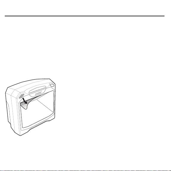
Unpacking
Carefully remove the DS7708 from the packaging to avoid damaging the scan window.
Once removed from its packaging, inspect it for damage. Keep the packaging. It is the
approved shipping container, and should be used if the scanner needs to be returned for
servicing. Before using the scanner peel off the protective cover from the scan window.
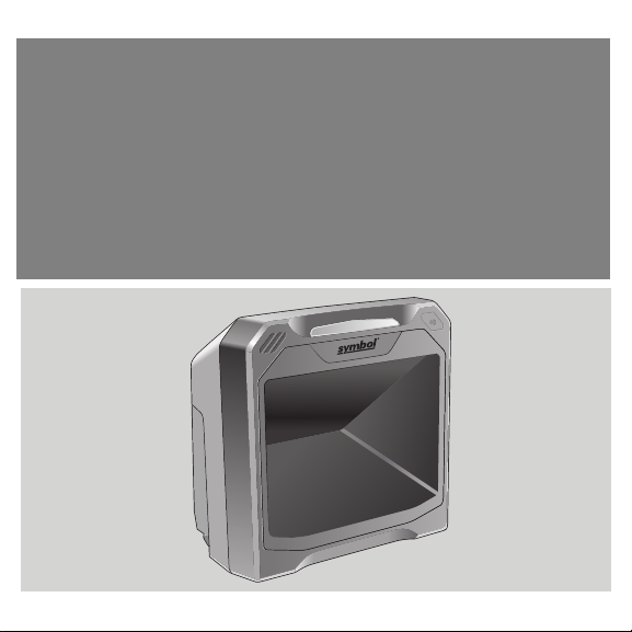
Product Features
The DS7708 scanner reads bar codes quickly and accurately with a minimum of
effort. The scanner includes an Electronic Article Surveillance (EAS) antenna
which allows simultaneous bar code reading and security tag deactivation.
4 DS7708 2D VERTICAL SLOT SCANNER
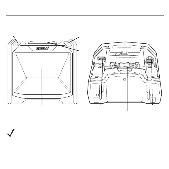
The DS7708 can sit on table top, or be attached to a wall mounting surface.
Speaker
Scan Window Opening
Volume/Tone
Control
LED
Auxiliary Scanner Port
EAS Cable
Host Port
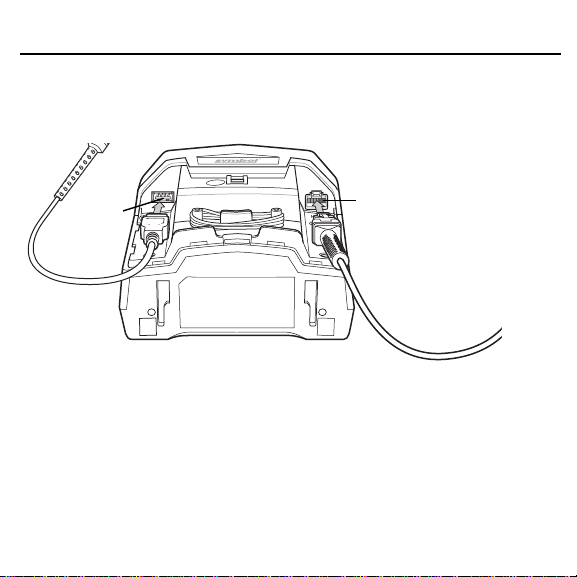
Connecting to a Host and/or Auxiliary Scanner
NOTE For detailed host configurations and connections refer to the
Product Reference Guide.
The scanner has two ports at its bottom. Remove the back cover (see Removing
the Back Cover on page 5) and turn the scanner upside down for access to the
host and auxiliary scanner ports.
Quick Reference Guide 5
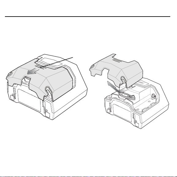
Removing the Back Cover
To remove the back cover, lightly press on the indentations at the top of the cover,
slide downward until it becomes free, and lift up off the scanner.
Press
6 DS7708 2D VERTICAL SLOT SCANNER
Insert the host cable into the RJ-45 connector on the back right of the scanner.
Insert auxiliary scanner cable (optional) into the USB connector on the back left of
the scanner.
Auxiliary
Port
Host Port
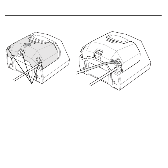
Replacing the Back Cover
The back cover has three channels to route the outgoing cables so that they are
organized and do not hinder the scanner’s placement. Place the back cover on
the back of the scanner and ensure the cables are positioned appropriately to be
routed through one or more of the cable routing channels. Route the cables
through the nearest channel. (See the figure on page 7.)
Quick Reference Guide 7
Press the cover and slide upwards until it snaps into place.
Cable Routing Channels
Removing the Back Cover with Cables Installed
Follow the procedure noted in Removing the Back Cover on page 5 and slide the
cable(s) out of the retaining slots to ensure they can move freely.
8 DS7708 2D VERTICAL SLOT SCANNER
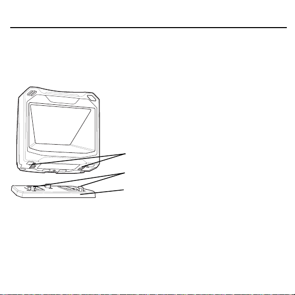
Mounting the Scanner (Optional Hardware Required)
The DS7708 is designed to sit on top of a table, or be mounted to a wall. The
mounting slots in the bottom of the scanner accept a mounting bracket to secure it
to the mounting surface.
Mounting Slots
Plastic Tabs
Mounting Bracket
Attaching the Scanner to the Table Top
The recommended method of installation is attaching the scanner to the table top
using the double-sided tape provided on the bottom of the bracket. Determine the
location for installing the scanner; attach the scanner to the mounting bracket;
peel off the paper on the two strips of double-sided tape; position the bracket; and
press down onto the table surface.
Quick Reference Guide 9
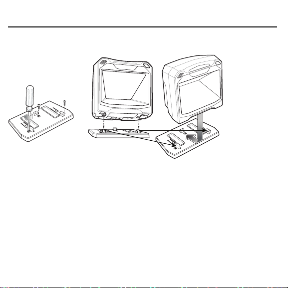
Mounting the Scanner to a Table Top
13
1. Follow the steps in Connecting to a Host and/or Auxiliary Scanner on page 4
to connect all interface and power cables to the scanner. Ensure the back
cover is replaced and the cables are routed appropriately.
2. Determine the location for installing the scanner.
3. Diagram 1: Mount the table bracket with three screws (not included).
4. Diagram 2: Invert the scanner slightly and align the mounting slots over the
plastic tabs on the bracket.
5. Diagram 3: Insert the plastic tabs into the mounting slots on the scanner, and
slide the scanner back until it clicks into place.
2
10 DS7708 2D VERTICAL SLOT SCANNER
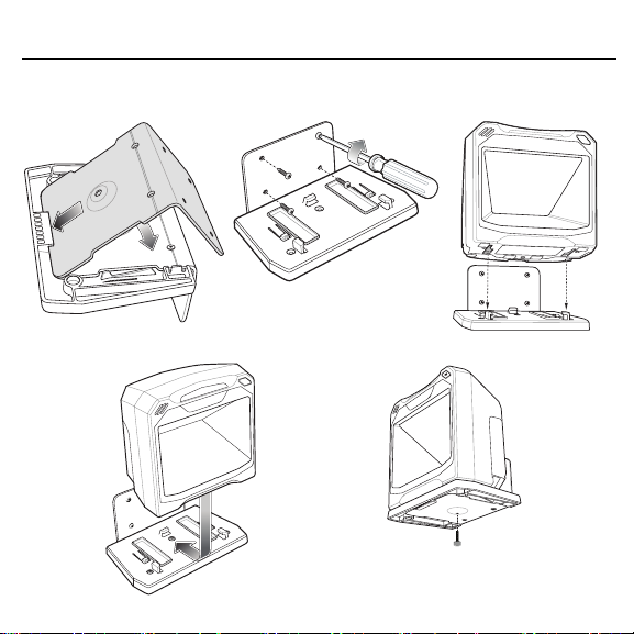
Mounting the Scanner to a Wall
1
4
2
5
3

Quick Reference Guide 11
1. Follow the steps in Connecting to a Host and/or Auxiliary Scanner on page 4
to connect all interface and power cables to the scanner. Ensure the back
cover is replaced and the cables are routed appropriately.
2. Determine the location for installing the scanner.
3. Use a pencil to mark the four mounting holes. (A mounting template is
provided in the Product Reference Guide.)
4. Diagram 1: Insert the back metal bracket under the plastic hook in the base
plate and set in place so that the thumb screw holes align.
5. Place the mounting bracket in position over the drilled holes with its flat
surface facing the mounting surface.
6. Diagram 2: Insert four screws (provided) through the holes and fasten to the
mounting surface.
7. Diagram 3: Invert the scanner slightly and align the mounting slots over the
plastic tabs on the bracket.
8. Diagram 4: Insert the plastic tabs into the mounting slots on the scanner, and
slide the scanner back until it clicks into place.
9. Diagram 5: To secure the scanner in the bracket, insert the thumb screw
(provided) through the hole in the bottom of the bracket and fasten to the
scanner bottom.
Removing the Scanner from the Mounting Bracket
To remove the scanner:
1. Grasp the scanner firmly on both sides.
2. Slide the scanner forward and lift out.
 Loading...