

Page 1
OPERATIONS MANUAL
Powe
r
!
O
K
B
e
i S
ta
p
e
lm
o
n
ta
g
e
A
u
fk
le
b
e
r
e
n
tf
e
r
n
e
n
u
n
d
K
o
n
t
a
k
tträ
g
e
r
m
o
n
tie
r
e
n
F
o
r
s
ta
c
k
m
o
u
n
tin
g
r
e
m
o
v
e
la
b
e
l
a
n
d
in
s
ta
ll c
o
n
ta
c
t
c
a
r
r
ie
r
ba76095d02 01/2013
MIQ/Blue PS Set
SET FOR WIRELESS DATA TRANSMISSION IN THE IQ SENSOR NET
Page 2

MIQ/Blue PS
CE conformity WTW herewith declares that the MIQ/Blue PS instrument is in compli-
ance with the basic requirements and other relevant regulations of the
directive 1999/5/EC.
The EC conformity declaration is available on request from WTW.
Copyright
© Weilheim 2013, WTW GmbH
Reprinting - even as excerpts - is only allowed with the explicit written
authorization of WTW GmbH, Weilheim.
Printed in Germany.
2 ba76095d02 01/2013
Page 3

MIQ/Blue PS Contents
MIQ/Blue PS - Contents
1 Overview . . . . . . . . . . . . . . . . . . . . . . . . . . . . . . . . . . . . 1-1
1.1 How to use this component operating manual . . . . . . . . 1-1
1.2 Features of the MIQ/Blue PS . . . . . . . . . . . . . . . . . . . . . 1-2
1.2.1 General characteristics . . . . . . . . . . . . . . . . . . . 1-2
1.2.2 Instrument identification . . . . . . . . . . . . . . . . . . 1-3
1.2.3 Application examples . . . . . . . . . . . . . . . . . . . . 1-4
2 Safety instructions . . . . . . . . . . . . . . . . . . . . . . . . . . . . 2-1
2.1 Authorized use . . . . . . . . . . . . . . . . . . . . . . . . . . . . . . . . 2-2
2.2 General safety instructions . . . . . . . . . . . . . . . . . . . . . . . 2-2
3 Installation . . . . . . . . . . . . . . . . . . . . . . . . . . . . . . . . . . 3-1
3.1 Scope of delivery . . . . . . . . . . . . . . . . . . . . . . . . . . . . . . 3-1
3.2 Basic information on installation . . . . . . . . . . . . . . . . . . . 3-1
3.2.1 General information . . . . . . . . . . . . . . . . . . . . . . 3-1
3.2.2 Power supply . . . . . . . . . . . . . . . . . . . . . . . . . . . 3-2
3.2.3 Topology and terminator switch . . . . . . . . . . . . 3-3
3.3 Radio range . . . . . . . . . . . . . . . . . . . . . . . . . . . . . . . . . . 3-8
3.4 Installation in the IQ S
3.5 Electrical connections: General instructions . . . . . . . . 3-14
3.6 Connecting the voltage supply . . . . . . . . . . . . . . . . . . . 3-16
3.6.1 Connection to 100 ... 240 V AC . . . . . . . . . . . . 3-16
3.6.2 Connection to 24 V DC . . . . . . . . . . . . . . . . . . 3-20
3.7 Figure of the terminal strip . . . . . . . . . . . . . . . . . . . . . . 3-23
ENSORNET . . . . . . . . . . . . . . . . . 3-13
4 Maintenance and cleaning . . . . . . . . . . . . . . . . . . . . . 4-1
4.1 Maintenance . . . . . . . . . . . . . . . . . . . . . . . . . . . . . . . . . . 4-1
4.2 Cleaning . . . . . . . . . . . . . . . . . . . . . . . . . . . . . . . . . . . . . 4-1
5 What to do if ... . . . . . . . . . . . . . . . . . . . . . . . . . . . . . . . 5-1
5.1 Check of the radio connection . . . . . . . . . . . . . . . . . . . . 5-1
5.2 Error causes and remedies . . . . . . . . . . . . . . . . . . . . . . 5-2
ba76095e02 01/2013
6 Technical data . . . . . . . . . . . . . . . . . . . . . . . . . . . . . . . 6-1
6.1 Electrical data . . . . . . . . . . . . . . . . . . . . . . . . . . . . . . . . 6-1
6.1.1 Operation without line power supply unit . . . . . 6-1
6.1.2 Operation with line power supply unit . . . . . . . . 6-1
6.1.3 Electrical connections . . . . . . . . . . . . . . . . . . . . 6-3
0 - 1
Page 4

Contents MIQ/Blue PS
6.2 Radio transmission . . . . . . . . . . . . . . . . . . . . . . . . . . . . .6-3
6.3 Instrument safety . . . . . . . . . . . . . . . . . . . . . . . . . . . . . .6-3
7 Appendix: Installation instructions for several radio
links . . . . . . . . . . . . . . . . . . . . . . . . . . . . . . . . . . . . . . . . 7-1
7.1 General information . . . . . . . . . . . . . . . . . . . . . . . . . . . .7-1
7.2 Application example for several radio links . . . . . . . . . . .7-1
7.3 Power supply . . . . . . . . . . . . . . . . . . . . . . . . . . . . . . . . .7-2
8 Contact Information . . . . . . . . . . . . . . . . . . . . . . . . . . . 8-3
8.1 Ordering & Technical Support . . . . . . . . . . . . . . . . . . . .8-3
8.2 Service Information . . . . . . . . . . . . . . . . . . . . . . . . . . . . .8-3
0 - 2
ba76095e02 01/2013
Page 5
MIQ/Blue PS Overview
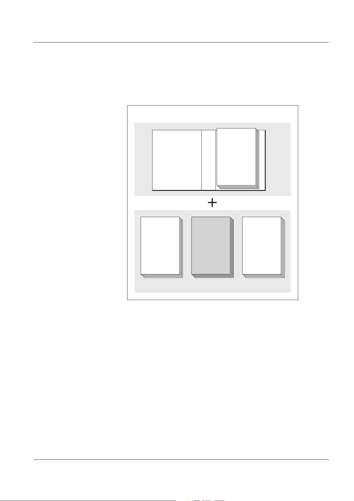
IQ Sensor Net Operating Manual
System
Operating
Manual
(Ring Binder)
IQ Sensor
Operating
Manual
MIQ Module
Operating
Manual
MIQ Terminal
Operating
Manual
Component Operating Manuals
1Overview
1.1 How to use this component operating manual
Structure of the
IQ S
ENSORNET operating
manual
ba76095e02 01/2013
Fig. 1-1 Structure of the IQ SENSORNET operating manual.
The IQ SENSORNET operating manual has a modular structure like the
IQ S
ENSORNET system itself. It consists of a system operating manual
and the operating manuals of all the components used.
Please file this component operating manual into the ring binder of the
system operating manual.
1 - 1
Page 6
Overview MIQ/Blue PS
MIQ/Blue PS
Island 1 Island 2
(Power) (Power)
Radio
B
e
i
S
t
a
p
e
lm
o
n
ta
g
e
A
u
fk
le
b
e
r
e
n
tfe
r
n
e
n
u
n
d
K
o
n
t
a
k
tt
r
ä
g
e
r
m
on
tie
re
n
F
o
r
s
t
a
c
k
m
o
u
n
t
in
g
re
m
o
v
e
la
b
e
l
a
n
d
in
s
ta
ll
c
o
n
ta
c
t
c
a
r
r
ie
r
Powe
r
!
O
K
1.2 Features of the MIQ/Blue PS
1.2.1 General characteristics
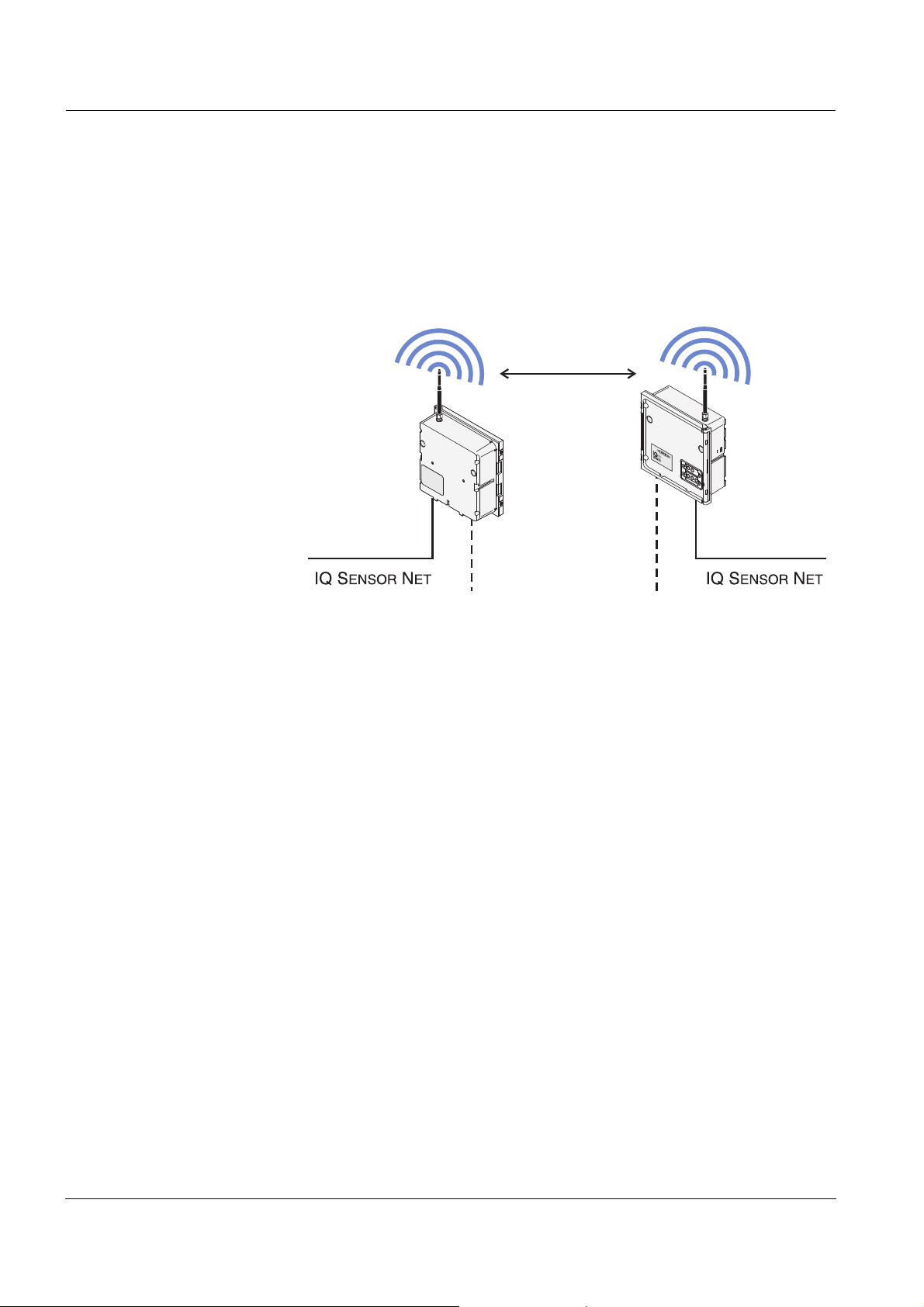
With the aid of the MIQ/Blue PS SET you can replace an
IQ S
ENSORNET line section by a radio link. When doing so a new
IQ S
ENSORNET island is formed (Fig. 1-2):
Fig. 1-2 Structure of a radio link with the MIQ/Blue PS SET
Radio technology using Bluetooth modules features reliability and
insensitivity to foreign electromagnetic radiation. Transmission
between two MIQ/Blue PS modules of a set takes place in an encoded
form. In conjunction with the proprietary IQ S
ENSORNET record, the
transmission is thus tap-proof.
The antennas of the MIQ/Blue PS modules are omni-antennas without
directivity.
Power supply To supply an IQ S
ENSORNET island with power, a line power supply unit
is integrated in the MIQ/Blue PS. I can supply components with a total
power consumption of up to 7 watt, which is sufficient for most applications. The line power supply unit of the MIQ/Blue PS can be supplied
with line power or with 24 V. Thus, an island can also be supplied by a
battery or solar system.
Terminal strip The MIQ/Blue PS has the following electrical connections on the termi-
nal strip inside the enclosure:
1 x line power connection 100 ... 240 VAC, two-pole
1 x line power connection 24 VDC, two-pole
3 x SENSORNET connections
1 - 2
ba76095e02 01/2013
Page 7
MIQ/Blue PS Overview
Ser.-Nr.xxxxxxxxx
Power
!
OK
YSI
MIQ/
Blue PS
Netz/ Mains Ausgang/Output
100...240VAC 22 V DC
12W 7 W
50 / 60 Hz
Eingang/Input Ausgang/Output
24V DC 22V DC
24W 24W
SENSOR NET / Input
24V DC 0,6W
ID-Nr: XXXX
Master
This device contains
FCC ID:PVH090202S
IC:5325A-090202S
ID number of the module pair
Function:
Master or slave (here: master)
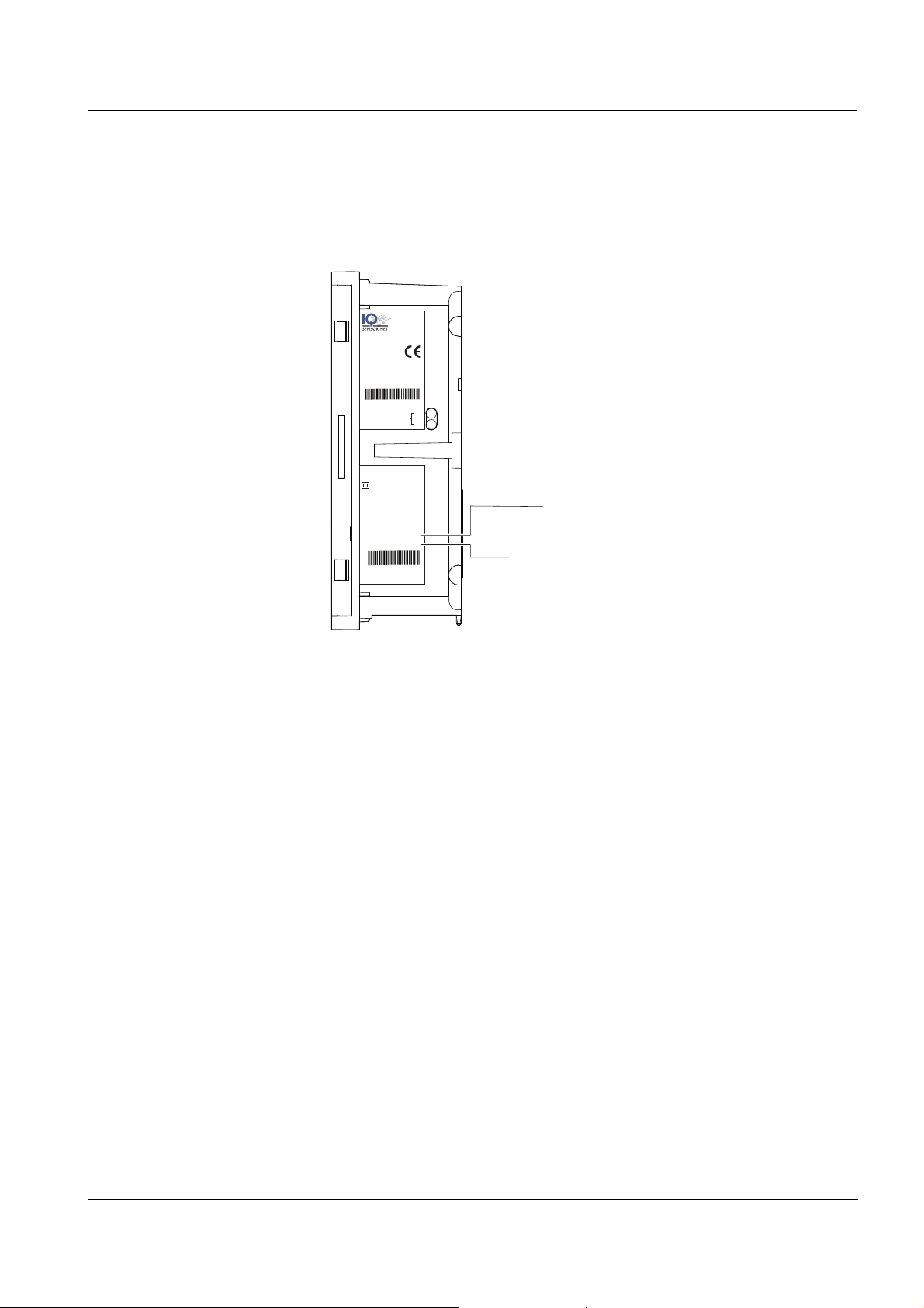
1.2.2 Instrument identification
The nameplate is on the side of the module enclosure. Among other, it
contains the following information (Fig. 1-3):
Fig. 1-3 Nameplate of the MIQ/Blue PS
ID number and encoding An MIQ/Blue PS SET consists of a module pair with the same ID num-
ber. Every module pair has its own coding of the radio transmission,
which is determined via the ID number. Any ID number is assigned only
once by YSI.This excludes the possibility of several module pairs having the same encoding and thus, of interferences by a module pair that
happens to have the same encoding. With several MIQ/Blue PS pairs,
the ID number enables to identify which pair communicates with each
other.
ba76095e02 01/2013
1 - 3
Page 8
Overview MIQ/Blue PS
0/4-20 mA
or field bus
MIQ/Blue PS
+MIQ/TC 2020
MIQ/Blue PS
PLC
Power
Power
Final sedimentation tank
Radio
PowerPower
!
O
K
OK
C
M
S
E
S
C
O
K
PowerPower
!
O
K
OK
Final sedimentation tank
0/4-20 mA
or field bus
MIQ/Blue PS
DIQ/S 182
PLC
Power
DIQ/S 182
PowerPower
!
O
K
OK
Power
Radio
MIQ/Blue PS
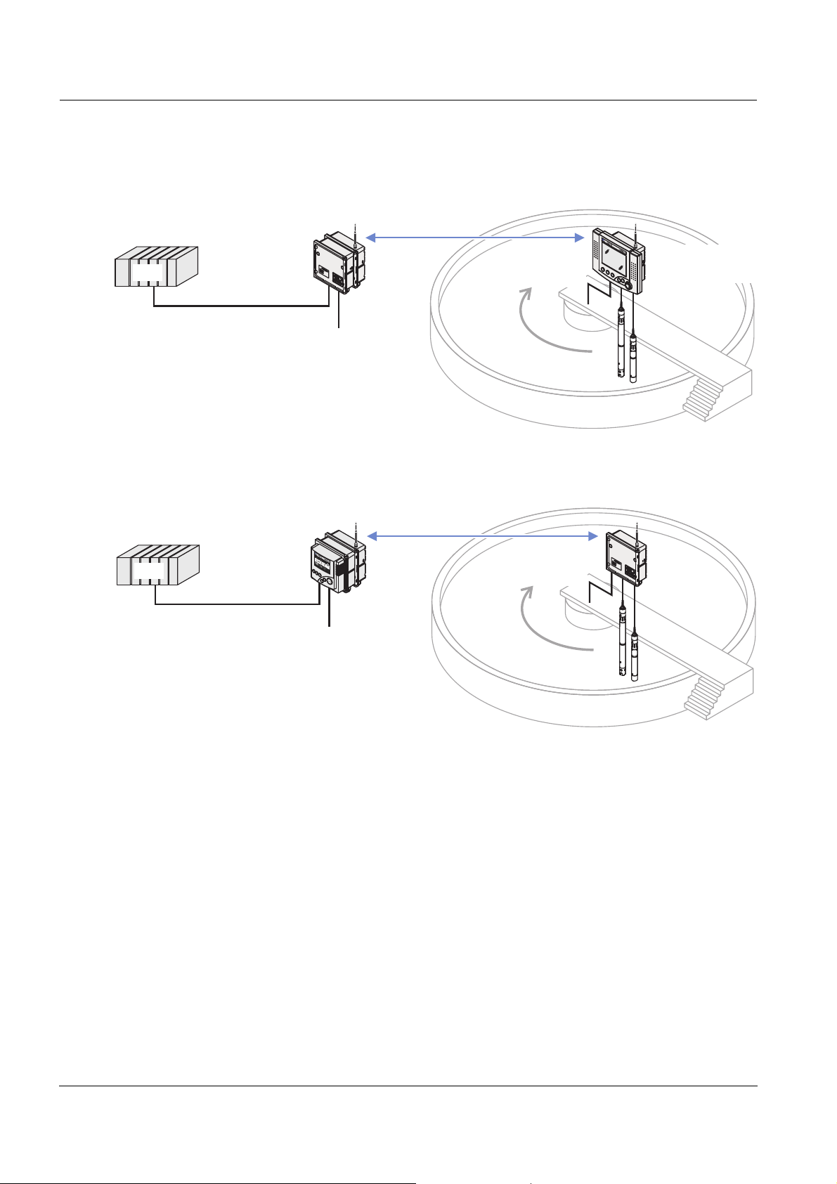
1.2.3 Application examples
Fig. 1-4 Example 1: Basin with rotating scraper bridge
1 - 4
Fig. 1-5 Example 2: Basin with rotating scraper bridge
ba76095e02 01/2013
Page 9
MIQ/Blue PS Safety instructions
2 Safety instructions
This component operating manual contains special instructions that
must be followed during the installation of the MIQ/Blue PS power supply module. Thus, it is essential to read this component operating manual before carrying out any work using this component. In addition to
this manual, the S
ing manual must be followed.
Always keep this component operating manual together with the system operating manual and all other component operating manuals in
the vicinity of the IQ S
AFETY chapter of the IQ SENSORNET system operat-
ENSORNET system.
Special user
qualifications
General safety
instructions
Other labels
The MIQ/Blue PS may only be connected to the line power supply by a
trained electrician.
Safety instructions in this operating manual are indicated by the warning symbol (triangle) in the left column. The signal word (e.g. "CAUTION") indicates the danger level:
Warning
indicates instructions that must be followed precisely in order to
prevent serious dangers to personnel.
Caution
indicates instructions that must be followed precisely in order to
avoid slight injuries to personnel or damage to the instrument or
the environment.
Note
indicates notes that draw your attention to special features.
Note
indicates cross-references to other documents, e.g. operating manuals.
ba76095e02 01/2013
2 - 1
Page 10

Safety instructions MIQ/Blue PS
2.1 Authorized use
Authorized use of the MIQ/Blue PS is its use as a radio module with
optional line power supply unit in the IQ S
ENSORNET.
Please observe the technical specifications according to
chapter 6 T
ECHNICAL DATA. Only operation according to the instructions
in this operating manual is authorized.
Any other use is considered to be unauthorized. Unauthorized use
invalidates any claims with regard to the guarantee.
2.2 General safety instructions
The MIQ/Blue PS is constructed and inspected according to the relevant guidelines and norms for electronic instruments (see
chapter 6 T
It left the factory in a safe and secure technical condition.
ECHNICAL DATA).
Function and opera-
tional safety
The failure-free function and operational safety of the MIQ/Blue PS is
only guaranteed if the generally applicable safety measures and the
special safety instructions in this operating manual are followed during
its use.
The failure-free function and operational safety of the MIQ/Blue PS is
only guaranteed under the environmental conditions that are specified
in chapter 6 T
ECHNICAL DATA.
Safe operation If safe operation is no longer possible, the MIQ/Blue PS must be taken
out of operation and secured against inadvertent operation.
Safe operation is no longer possible if the MIQ/Blue PS:
has been damaged in transport
has been stored under adverse conditions for a lengthy period of
time
is visibly damaged
no longer operates as described in this manual.
If you are in any doubt, contact the supplier of your MIQ/Blue PS.
2 - 2
ba76095e02 01/2013
Page 11

MIQ/Blue PS Installation
3 Installation
3.1 Scope of delivery
The scope of delivery of the MIQ/Blue PS module includes:
MIQ/Blue PS
Accessory set, including
– 4 x cable glands (clamping range 4.5-10 mm) with seals and blind
plugs
– 4x ISO blind nuts M4 with suitable socket head screws and plain
washers
– 2x countersunk screws M3x8 to close the module lid
(+ 2 spare ones)
– 1 x contact base with fixing screws
Accessories for range test with attenuator
(see section 3.3)
– 1 x SMA attenuator VAT 10 dB
– 2 x reverse SMA adapters for SMA attenuator
Operating manual.
3.2 Basic information on installation
3.2.1 General information
The MIQ/Blue PS radio modules are preconfigured in pairs and ready
for installation. Installation consists only of the connection to the
IQ S
ENSORNET.
Note
This chapter describes the installation of one radio link in the
IQ S
ENSORNET system. If several radio links should be installed, the
instructions in the appendix of this operating manual have to be followed additionally.
Note
To prevent the radio transmission from being affected by water or snow
collecting on the antenna, we urgently recommend protecting any MIQ/
Blue PS radio modules against precipitation with the aid of a plastic
canopy (SSH/IQ).
ba76095e02 01/2013
3 - 1
Page 12

Installation MIQ/Blue PS
3.2.2 Power supply
The line power supply unit of the MIQ/Blue PS can be used for the
exclusive supply of an IQ S
power rating has to be made for each IQ S
ENSORNET island. In any case, a separate
ENSORNET island.
Power delivery
Compatibility with other
line power supply units
Example Problem:
24 V DC operation: 24 W
100 ... 240 V AC operation: 7 W
If the installation of further line power supply units should be necessary,
please note the following: If other power supply modules (e.g. MIQ/PS)
are installed on the IQ S
ENSORNET island, the line power supply unit of
the MIQ/Blue PS is automatically inactive. Connecting the MIQ/
Blue PS line power supply unit to a power supply remains ineffective
here. In this case, the MIQ/Blue PS is a consumer with a power consumption of 0.6 W in the power rating.
An IQ SENSORNET island should consist of the following compo-
nents plus the MIQ/Blue PS:
Component Power requirement
[W]
VisoTurb
ViSolid
SensoLyt
®
700 IQ 1.5
®
700 IQ 1.5
®
700 IQ 0.2
MIQ/CHV PLUS 1.0
MIQ/TC 2020 XT (docked from time to time) 3.0
In this example, the MIQ/Blue PS and the MIQ/CHV PLUS should
be mounted as a stack.
The IQ S
ENSORNET system should be supplied with 100 ...
240 V AC.
Solution/proceeding:
First it is assumed that the MIQ/Blue PS suffices for power supply.
It does not have to be taken into account as a consumer. In the worst
case, i. e. with a docked MIQ/TC 2020 XT, the power requirement of
all components is 7.2 W. Power losses in cables do not have to be
taken into account due to the stack mounting.
Power rating: The calculated power requirement is greater than the
maximum power delivery of the MIQ/Blue PS line power supply unit.
Therefore, an additional power supply module has to be installed
(e.g. MIQ/PS).
New power rating: The MIQ/Blue PS has to be counted as a con-
sumer as well. Therefore, the power consumption is now 7.8 W.
3 - 2
ba76095e02 01/2013
Page 13
MIQ/Blue PS Installation
X6 X5 X4
SENSORNET 2
RED
SHIELD
GREEN
X3 X2 X1
SENSORNET 1
RED
SHIELD
GREEN
ON
OFF
SN TERMINATOR
SN Terminator
With an MIQ/PS power supply module (18 W), there is still an
energy reserve of 10.2 W for any future extensions.
3.2.3 Topology and terminator switch
For failure-free operation, the terminator switches (terminating resistors) must always be set to ON on two MIQ modules of the
ENSORNET island. On which modules this is required results from
IQ S
the topology of the IQ S
ENSORNET island:
ba76095e02 01/2013
Fig. 3-1 Correct setting of the terminator switches
Main line (trunk
line)
Longest cable section with terminator switches at
its ends.
The terminator switches must be set to On at both
ends.
If all MIQ modules are located at one point, i. e. in
a module stack, the length of the main line is zero
(star-shaped wiring).
Branch line All lines branching from the main line.
Branch lines can be branched further.
3 - 3
Page 14
Installation MIQ/Blue PS
L1
= 150 m
L4 = 200 m
L2 = 200 m L3 = 300 m
Special features with
certain configurations
Example of determining
the main line
If, except in the MIQ/Blue PS, no other terminator switch is available
on the IQ S
ENSORNET island, it must be set to ON. In addition, a ter-
minating resistor (included in the scope of delivery) must be connected to one of the three SENSORNET connectors. For more
details, see page 3-6.
If a DIQ/S 182 Universal Transmitter is on the IQ S
all
terminator switches on the IQ SENSORNET island must be set to
ENSORNET island,
ON.
The following figure shows the main line L made up of the partial
lengths L1, L2 and L3 as the cable section L4 is shorter than L3:
Length of the main line = L1 + L2 + L3
3 - 4
Fig. 3-2 Example of determining the length of the main line
ba76095e02 01/2013
Page 15
MIQ/Blue PS Installation
X6 X5 X4
SENSORNET 2
RED
SHIELD
GREEN
X3 X2 X1
SENSORNET 1
RED
SHIELD
GREEN
ON
OFF
SN TERMINATOR
SN Terminator
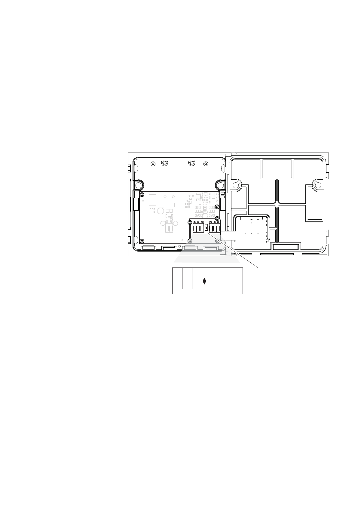
Terminator switch Terminator switches are located in each MIQ module between the two
SENSORNET connections on the right of the terminal strip (designation "SN TERMINATOR").
Fig. 3-3 Terminator switch
ba76095e02 01/2013
3 - 5
Page 16

Installation MIQ/Blue PS
6
8
7
9
2
1
3
5
4
SN terminator
switch ON
additional terminating resistor
X13
X12
100...
240V AC
MAINS
L1
N
X11
X10
24V DC
INPUT
POWER
SENSORNET 2
SENSORNET 1
ON
OFF
X6
RED
RED
SN TERMINATOR
SHIELD
GREEN
SHIELD
GREEN
X5
X4
X3
X2
X1
SENSORNET 3
X8
X9
X7
RED
SHIELD
GREEN
+
-
RRR
connection selectable
Additional terminating
resistor on the MIQ/
Blue PS
An additional terminating resistor is only required if, except in the MIQ/
Blue PS, no other terminator switch is available on the IQ S
ENSORNET
island. The terminating resistor is connected to one of the three SENSORNET connectors (Fig. 3-4). The terminating resistor must bridge
the two outside terminals of the SENSORNET connector. The SENSORNET connector can still be used to connect a sensor.
Fig. 3-4 MIQ/Blue PS with additional terminating resistor
3 - 6
ba76095e02 01/2013
Page 17

MIQ/Blue PS Installation
ON
Power
PowerPower
!
O
K
OK
C
M
S
E
S
C
O
K
PowerPower
!
O
K
OK
PowerPower
!
O
K
OK
PowerPower
!
O
K
OK
Power
DIQ/S 182
PowerPower
!
O
K
O
K
Power
ON+R
R = additional terminating resistor
OFF
OFF
ON+R
ON
ON OFF
ON
PowerPower
!
O
K
OK
PowerPower
!
O
K
OK
Examples of the correct
setting of the terminator
switches
The figure on the following page demonstrates with several examples
of IQ S
ENSORNET islands how the terminator switches and terminating
resistors are correctly set.
Fig. 3-5 Terminator switches and terminating resistors
ba76095e02 01/2013
3 - 7
Page 18

Installation MIQ/Blue PS
Radio (maximum distance)
PowerPower
!
OKOK
PowerPower
!
OKOK
MIQ/Blue PS
MIQ/Blue PS
3.3 Radio range
The range of a radio link with MIQ/Blue PS SET in the free field is up to
100 m with installation and testing according to this chapter (see
chapter 6 T
As with any other radio technology, the following points have to be
observed when installing the MIQ/Blue PS SET:
All materials (even window glass) in the radio link reduce the range.
Therefore, keep the radio link free of barriers (even temporary
ones). Both MIQ/Blue PS modules should be in permanent "visual
contact" through the air. Take into account that there may be shorttime events such as trucks driving by that interrupt the radio link.
Water, snow and ice on the antenna will reduce the range. When it
is installed in the free field, protect the MIQ/Blue PS against water,
snow and ice. Use the plastic canopy SSH/IQ for this.
Canopies made out of metal or PVC reduce the range!
ECHNICAL DATA).
A high location of the MIQ/Blue PS increases the range. If neces-
Fig. 3-6 Height of the location for the MIQ/Blue PS module
Install the MIQ/Blue PS where the mentioned requirements are best
sary, install the MIQ/Blue PS higher over ground.
available and establish the connection to the IQ S
ENSORNET island
with the aid of the SNCIQ cable. Do not in any case use an antenna
extension cable to improve the position of the antenna alone.
Antenna extension cables cause range losses.
3 - 8
Mount the MIQ/Blue PS outside of a building on a pole and run the
SNCIQ cable through the wall to the next MIQ module.
ba76095e02 01/2013
Page 19

MIQ/Blue PS Installation
Antenna
extension
PowerPower
!
OK
PowerPower
!
OK
PowerPower
!
OK
PowerPower
!
OK
Power
!
OKO
K
Po
we
r
Po
wer
!
OK
Po
we
r
Po
wer
!
OK
PowerPower
!
OK
PowerPower
!
OK
SNCIQ
Example: IQ SENSORNET
island in a building.
Fig. 3-7 Installation of the MIQ/Blue PS
Note
When installing several radio links:
Follow the "Master" or "Slave" labeling of the individual MIQ/Blue PS
modules. The labeling of a MIQ/Blue PS module is on the name plate
(see section 1.2.2):
Mount every MIQ/Blue PS master with a maximum distance to the
next master (at least 50 m).
ba76095e02 01/2013
Mount every MIQ/Blue PS slave with a minimum distance of 2 m to
the next slave.
3 - 9
Page 20

Installation MIQ/Blue PS
Master 1
Po
w
e
r
Po
w
e
r
!
OKOK
Radio
Po
we
r
Po
we
r
!
OKO
K
Master 2
Pow
e
r
Pow
er
!
OKO
K
Radio
Po
w
e
r
Po
w
e
r
!
OKOK
Antenna distance at least !50 mMaster - Master:
Slave 2
Slave 1
Master 1
P
o
we
r
P
o
we
r
!
OKOK
P
ow
e
r
P
ow
e
r
!
OKO
K
P
o
w
e
r
P
o
w
e
r
!
OKO
K
Po
we
r
Po
we
r
!
OKOK
Slave 2
Slave 1
PowerPowe
r
!
OKOK
Master 3
P
o
we
r
P
o
we
r
!
OKOK
Po
w
e
r
Po
w
er
!
OKO
K
Master 4
Pow
e
r
Pow
e
r
!
OKOK
Slave 4
Slave 3
Radio
Radio
Radio
Radio
Antenna distance Master - Master: at least !50 m
Master 2
Master 1
PowerPower
!
OKOK
P
o
w
e
r
P
o
w
er
!
OKO
K
Master 2
Po
w
e
r
Po
w
er
!
OKO
K
P
o
w
e
r
P
o
w
er
!
OKOK
Po
we
r
Po
wer
!
OKO
K
Master 3
PowerPower
!
OKOK
P
o
w
e
r
P
o
w
er
!
OKOK
Master 4
Po
w
e
r
Po
w
e
r
!
OKOK
Radio
Radio
Radio
Radio
Slave 3Slave 2Slave 1 Slave 4
Antenna distance Master - Master: at least !50 m
Maximum distance of
the MIQ/Blue PS
masters (examples)
Fig. 3-8 Example 1: Maximum distance of the MIQ/Blue PS masters
Fig. 3-9 Example 2: Maximum distance of the MIQ/Blue PS masters
3 - 10
Fig. 3-10 Example 3: Maximum distance of the MIQ/Blue PS masters
ba76095e02 01/2013
Page 21

MIQ/Blue PS Installation
Note
If it is not possible to keep the minimum distances of the MIQ/Blue PS
masters, you can reduce interferences of the radio communication by
shielding the modules against one another (e.g. by using directional
antennas with side-lobe suppression in conjunction with attenuators). If
necessary, contact a radio technology specialist.
Note
If high gain antennas in order to increase the range are used, the
requirements of the directive 1995/5/EC will not be met.
Range test with
attenuator
To test the quality of the radio link, carry out the following test with a
defined signal attenuation:
Note
If a canopy is used, the MIQ/Blue PS has to be mounted lower on the
canopy for the duration of the range test. If necessary, use the lower
boreholes in the plastic canopy (SSH/IQ) for this.
1 Unscrew the antenna from on of the two MIQ/Blue PS mod-
ules. For the test, insert the attenuator with both adapters
between the antenna connector of the module enclosure and
the antenna.
2 Test the radio link with the attenuator under the most unfavor-
able conditions such as with installation on rotating scraper
bridges and the utmost distance of both MIQ/Blue PS modules.
If the test is successful with signal attenuation, faultless operation should also be possible under unfavorable conditions
(e.g. fog, heavy rainfall, snow).
3 To terminate the test operation, remove the attenuator and
mount the antenna directly on the MIQ/Blue PS again.
ba76095e02 01/2013
4 If you had mounted the MIQ/Blue PS lower on the canopy for
the test:
Mount the MIQ/Blue PS higher on the canopy again.
3 - 11
Page 22

Installation MIQ/Blue PS
Radio link check list:
1 Is there direct visual contact between the antennas of both
MIQ/Blue PS modules at any time (e.g. with installation on
moving scraper bridges)?
2 Is the radio link free from permanent disturbances? Examples:
– Obstacles (such as buildings, windows, etc.)
– Shielding (such as a metal or PVC canopy)
3 Is the radio link free from temporary disturbances? Examples:
– Regular temporary disturbances (e.g. center support or
mounting stand, with installation on a moving scraper
bridge)
– Irregular temporary disturbances (e.g. vehicles or persons
crossing the radio link)
4 Are the antennas of the MIQ/Blue PS modules free of water,
snow, ice?
5 When using a canopy:
Is the SSH/IQ plastic canopy used
(no metal or PVC canopy)?
6 Are the antennas in the original condition (e.g. no antenna ex-
tension cable)?
7 Was the range test carried out with attenuator?
8 With installation on a moving scraper bridge:
Was the range test carried out for a complete rotation of the
scraper bridge?
9 Is the distance between 2 MIQ/Blue PS masters (for several ra-
dio links) at least 50 m?
10 Is the distance between 2 MIQ/Blue PS slaveS (for several ra-
dio links) at least 2 m?
Radio link check list For safe operation of a radio link, check the system with the following
check list.
The following checklist supports you when planning, projecting and
installing a radio link with the MIQ/Blue PS radio modules.
For smooth operation, you should be able to answer all questions with
"Yes".
Note
Interferences are possible also with short radio links if the radio signal
is reflected by walls that are outside the direct radio link. Due to reflections, radio signals may reach the receiver alleviated or several times.
In this case, changing the location of a MIQ/Blue PS module only
slightly can improve the transmission.
3 - 12
ba76095e02 01/2013
Page 23

MIQ/Blue PS Installation
3.4 Installation in the IQ SENSORNET
The IQ SENSORNET provides a number of options for integrating the
MIQ/Blue PS mechanically and electrically in the system (stacked
mounting, distributed mounting, etc.). The individual types of installation are described in detail in the I
operating manual.
Note
If there are several power supply modules in the IQ S
helpful if all the power supply modules are connected to a single power
supply. As a result, the system can be easily switched on and off from
a single location.
NSTALLATION chapter of the system
ENSORNET, it is
ba76095e02 01/2013
3 - 13
Page 24

Installation MIQ/Blue PS
Sealing ring 20 x 15 x 1 mm
Cable gland M16
Blind plug
Sealing ring 20 x 15 x 1 mm
Extension piece M16/M20
Sealing ring 24 x 19 x 2 mm
Cable gland M20
3.5 Electrical connections: General instructions
Cable glands All electric cables are fed into the enclosure of the MIQ/Blue PS from
below through prepared openings. Cable glands with different clamping
ranges are provided with the MIQ/Blue PS to provide sealing between
the cable and enclosure as well as for strain relief. Select the suitable
cable gland for the respective cable diameter:
Small, clamping range 4.5 to 10 mm. This cable gland is suitable for
all IQ S
ENSOR NET cables.
Large, clamping range 7 to 13 mm. This cable gland is required for
cable sheaths with an outer diameter of more than 10 mm and is
screwed into the enclosure via an extension piece.
Note
If necessary, you can order additional large cable glands as a set of 4
pieces (model EW/1, order number 480 051).
3 - 14
ba76095e02 01/2013
Page 25

MIQ/Blue PS Installation
General installation
instructions
Observe the following points when attaching connecting wires to the
terminal strip:
Shorten all the wires to be used to the length required for the instal-
lation
Always fit all the ends of the wires with wire end sleeves before con-
necting them to the terminal strip
Any wires that are not used and project into the enclosure must be
cut off as closely as possible to the cable gland.
In each of the remaining free openings, screw in a small cable gland
with sealing ring and close them with a blind plug.
Warning
No free wires must be allowed to project into the enclosure. Otherwise, there is a danger that areas safe to contact could come
into contact with dangerous voltages. This could result in life
threatening electric shock when working with the IQ S
Always cut off any wires that are not in use as closely as possible
to the cable gland.
ENSORNET.
ba76095e02 01/2013
3 - 15
Page 26

Installation MIQ/Blue PS
3.6 Connecting the voltage supply
The following two sections need only be observed if the IQ SENSORNET
island should be supplied with power by the MIQ/Blue PS.
3.6.1 Connection to 100 ... 240 V AC
Warning
If the power supply is connected incorrectly, it may represent a
danger to life from electric shock. Pay attention to the following
points during installation:
The MIQ/Blue PS may only be connected by a trained electri-
cian.
The connection of the MIQ/Blue PS to the power supply may
only be carried out when it is not carrying any voltage.
The power supply must fulfill the specifications given on the
nameplate and in chapter 6 T
When installed in a building, a switch or power switch must be
provided as an interrupt facility for the MIQ/Blue PS.
The interrupt facility must
– be installed in the vicinity of the MIQ/Blue PS, easily acces-
sible by the user, and
ECHNICAL DATA.
– be labeled as an interrupt facility for the MIQ/Blue PS.
After it has been installed, the MIQ/Blue PS may only be opened
if the mains voltage has been switched off beforehand.
Materials required Wire end sleeves, suitable for the power line, with suitable crimping
tool
1 x cable gland, suitable for the cable diameter (see section 3.5 on
page 3-14).
Tools Cable stripping knife
Wire stripper
Phillips screw driver
Small screw driver.
3 - 16
ba76095e02 01/2013
Page 27

MIQ/Blue PS Installation
ca. 45 mm
L
N
cut protective conducter here
Preparing the power
cable
1 Cut off the cable to the required length.
2 Strip the cable insulation for approx. 45 mm.
3 Bare the wires of phases L and N and fit them with wire end
sleeves.
4 If present, cut off the protective ground wire at the end of the
cable sheath.
Fig. 3-11 Prepared power cable.
Caution
The ground wire must not project into the enclosure. Otherwise,
malfunctions could occur.
ba76095e02 01/2013
3 - 17
Page 28

Installation MIQ/Blue PS
1
3
2
L
N
4
Connecting the power
line
5 Open the enclosure.
Fig. 3-12 Inserting the supply line.
6 Screw a cable gland (pos. 1 in Fig. 3-12) with sealing ring (pos.
2) into the enclosure below the power supply connection.
7 Loosen the coupling ring (pos. 3).
8 Feed the power line through the cable gland into the enclosure.
When doing so bend the flexible divider (pos. 4) to the right.
3 - 18
ba76095e02 01/2013
Page 29

MIQ/Blue PS Installation
3
NL
Terminal
labeling:
X13
X12
100...
240V AC
NETZ/MAINS
L1
N
Fig. 3-13 Line power connection.
Note
The complete assignment of the terminal strip is shown in section 3.7.
9 Connect phases L and N to the terminal strip. Make sure that
the cable assignment agrees with the specification on the terminal label under the terminal strip.
10 Tighten the coupling ring (pos. 3).
Warning
No free wires must be allowed to project into the enclosure. Otherwise, there is a danger that areas safe to contact could come
into contact with dangerous voltages. Always cut off any wires
that are not in use as closely as possible to the cable gland.
11 Close the enclosure.
ba76095e02 01/2013
3 - 19
Page 30

Installation MIQ/Blue PS
3.6.2 Connection to 24 V DC
Warning
If the 24 V DC supply is connected incorrectly, it may represent a
danger to life from electric shock. Pay attention to the following
points during installation:
The MIQ/Blue PS may only be connected by a trained electri-
cian.
The 24 V DC supply must meet the specifications quoted on the
nameplate and in chapter 6 T
age SELV).
The connection of the MIQ/Blue PS to the power supply may
only be carried out when it is not carrying any voltage.
When installed in a building, a switch or power switch must be
provided as an interrupt facility for the MIQ/Blue PS.
The interrupt facility must
– be installed in the vicinity of the MIQ/Blue PS, easily acces-
sible by the user, and
ECHNICAL DATA (protective low volt-
– be labeled as an interrupt facility for the MIQ/Blue PS.
Note
Battery systems should be protected against total discharge. The MIQ/
Blue PS has no integrated deep discharge protection.
Materials required Wire end sleeves, suitable for the 24 V AC/DC feed line, with suit-
able crimping tool
1 x cable gland, suitable for the cable diameter (see section 3.5 on
page 3-14).
Tools Cable stripping knife
Wire stripper
Phillips screw driver
Small screw driver.
Preparing the 24 V DC
line
1 Cut off the cable to the required length.
2 Strip the cable insulation for approx. 45 mm.
3 Bare the wires 1 and 2 and fit them with wire end sleeves.
3 - 20
ba76095e02 01/2013
Page 31

MIQ/Blue PS Installation
ca. 45 mm
wire 1
wire 2
1
3
2
4
-
+
Fig. 3-14 Prepared 24 V DC line.
Connecting the 24 V DC
line
4 Open the enclosure.
ba76095e02 01/2013
Fig. 3-15 Inserting the 24 V DC line.
5 Screw a cable gland (pos. 1 in Fig. 3-15) with sealing ring (pos.
2) into the enclosure below the 24 V DC connection.
6 Loosen the coupling ring (pos. 3).
7 Feed the 24 V DC line through the cable gland into the enclo-
sure. When doing so bend the flexible divider (pos. 4) to the
left.
3 - 21
Page 32

Installation MIQ/Blue PS
3
Terminal
labeling:
X11
X10
24V DC
EINGANG
INPUT
POWER
+
-
Fig. 3-16 Line power connection.
Note
The complete assignment of the terminal strip is shown in section 3.7.
8 Connect wires 1 and 2 to the terminal strip. Make sure that the
cable assignment agrees with the specification on the terminal
label under the terminal strip.
9 Tighten the coupling ring (pos. 3).
Warning
No free wires must be allowed to project into the enclosure. Otherwise there is the danger of short circuits that can cause a fire.
Always cut off any wires that are not in use as closely as possible
to the cable gland.
10 Close the enclosure.
3 - 22
ba76095e02 01/2013
Page 33

MIQ/Blue PS Installation
X13
X12
100...
240V AC
NETZ/MAINS
L1
N
X11
X10
24V DC
INPUT
POWER
SENSORNET 2
SENSORNET 1
ON
OFF
X6
RED
RED
SN TERMINATO R
SHIELD
GREEN
SHIELD
GREEN
X5
X4
X3
X2
X1
SENSORNET 3
X8
X9
X7
RED
SHIELD
GREEN
+
-
3.7 Figure of the terminal strip
Fig. 3-17 MIQ/Blue PS terminal strip
ba76095e02 01/2013
3 - 23
Page 34

Installation MIQ/Blue PS
3 - 24
ba76095e02 01/2013
Page 35

MIQ/Blue PS Maintenance and cleaning
4 Maintenance and cleaning
4.1 Maintenance
The MIQ/Blue PS requires no special maintenance. The general maintenance of IQ S
IQ S
ENSORNET system operating manual.
4.2 Cleaning
The cleaning of IQ SENSORNET components is described in the
IQ S
ENSORNET system operating manual.
ENSORNET components is described in the
ba76095e02 01/2013
4 - 1
Page 36

Maintenance and cleaning MIQ/Blue PS
4 - 2
ba76095e02 01/2013
Page 37

MIQ/Blue PS What to do if ...
6
8
7
9
2
1
3
5
4
Status LED
Radio boards
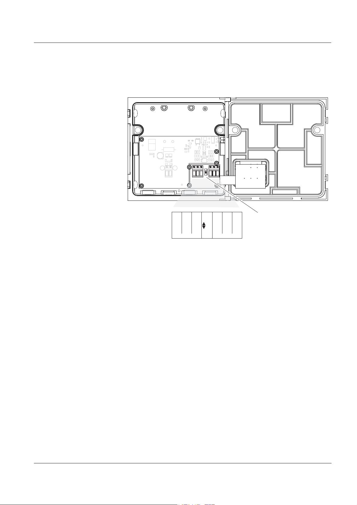
5 What to do if ...
5.1 Check of the radio connection
A yellow LED inside of both MIQ/Blue PS modules indicates the status
of the radio connection:
LED state Connection status
Permanently on Connection OK, no data transmission activity
Flickering Connection OK, data transmission active
Permanently off No connection
The status LED is located at the top edge of the rear radio board:
ba76095e02 01/2013
Fig. 5-1 Status LED radio connection
5 - 1
Page 38

What to do if ... MIQ/Blue PS
5.2 Error causes and remedies
Already established
radio connection does
no longer work
Range insufficient
Cause Remedy
– Obstacle in the radio link – Remove the obstacle
– Range at the limit – see following point, R
INSUFFICIENT
– Moisture on antenna surface – Wipe the antenna dry
– Use a canopy
– The radio link is not active
despite the display on the radio
PCB (status LED permanently
– Switch on and after 5 sec-
onds off again both MIQ/
Blue PS modules
on)
Cause Remedy
– Obstacle in the radio link – Remove the obstacle
– Mount the MIQ/Blue PS in a
higher position (e.g. on a
pole)
– Make sure there is "visual
contact" between the MIQ/
Blue PS modules
ANGE
– MIQ/Blue PS too close to the
ground
– Mount the MIQ/Blue PS in a
higher position (e.g. on a
pole)
– Shielding by metal canopy – Use plastic canopy SSH/IQ
5 - 2
ba76095e02 01/2013
Page 39

MIQ/Blue PS Technical data
6 Technical data
Note
General technical data on MIQ modules are given in the T
DATA chapter of the IQ SENSORNET system operating manual.
6.1 Electrical data
6.1.1 Operation without line power supply unit
Nominal voltage Max. 24 V DC via the IQ SENSORNET (for
details, see chapter T
IQ S
Power consumption 0.6 W
ENSORNET system operating manual).
ECHNICAL DATA of the
ECHNICAL
100 ... 240 V AC
operation
6.1.2 Operation with line power supply unit
Supply Nominal voltage:100 ... 240 V AC ± 10 %
Frequency: 50/60 Hz
according to DIN IEC 60038
Line power connection:2 pin, N and L
Line cross-section of mains connection:
Europe: 1.5 ... 4.0 mm
USA: AWG 14 ... 12
Fuse rating on the operator side: max. 16 A
Power consumption Approx. 12 W
Output voltage Max. 24 VDC via the IQ S
details, see chapter T
IQ S
ENSORNET system operating manual).
ENSORNET (for
ECHNICAL DATA of the
2
ba76095e02 01/2013
6 - 1
Page 40

Technical data MIQ/Blue PS
40 50 6020 300-30 -20 -10 10
0
1
2
3
4
5
6
7
8
Power output [W]
Ambient temperature [°C]
Admissible ambient temperature -20 … +55 °C
Power output Up to 47 °C (117 °F) ambient temperature
7 W; over 47 °C (117 °F) the power delivery
is reduced linearly to 4.4 W at 55 °C
(131 °F):
24 V DC operation
Protective class II
Overvoltage
II
category
Supply Input:23 ... 26.5 V DC / max. 1 A
protective low voltage
SELV (Safety
Extra Low Voltage)
Ripple:
<5%
Connection:2 pin
Line cross-section of connections:
Europe:1.5 ... 4.0 mm
2
USA:AWG 14 ... 12
Fuse rating on the operator side: max. 16 A
Power consumption Max. 24 W
6 - 2
Output voltage Max. 24 VDC via the IQ S
details, see chapter T
IQ S
ENSORNET system operating manual).
ENSORNET (for
ECHNICAL DATA of the
Power output Max. 24 W
ba76095e02 01/2013
Page 41

MIQ/Blue PS Technical data
X13
X12
100...
240V AC
NETZ/MAINS
L1
N
X11
X10
24V DC
EINGANG
INPUT
POWER
SENSORNET 2
SENSORNET 1
ON
EIN
OFF
AUS
X6
ROT
RED
ROT
RED
SN TERMINATO R
SCHIRM
SHIELD
GRÜN
GREEN
SCHIRM
SHIELD
GRÜN
GREEN
X5
X4
X3
X2
X1
SENSORNET 3
X8
X9
X7
ROT
RED
SCHIRM
SHIELD
GRÜN
GREEN
+
-
6.1.3 Electrical connections
Terminal strip inside the
enclosure
Terminals
Cable glands
Terminal type Screw-type terminal strip, accessible by
opening the lid
Terminal ranges Solid wires:
0.2 ... 4.0 mm
2
AWG 24 ... 12
2
Suitable for cable diam-
Flexible wires:
0.2 ... 2.5 mm
4.5 ... 10 mm or 7 ... 13 mm
eter
6.2 Radio transmission
Radio frequency 2.402 ... 2.480 GHz
Transmitting power max. 20 dBm or 100 mW
Bridgeable distance max. 100 m (328 ft)
The specified maximum range applies if the
radio link was installed and tested according
to this operating manual (see section 3.3).
6.3 Instrument safety
Used directives and
standards
ba76095e02 01/2013
In addition to the standards listed in the IQ SENSORNET system operating manual, the MIQ/Blue PS is based on the following directives and
standards:
Data radio – EEC directive 1999/5/EC
(R&TTE directive)
– EN 300 328-2
6 - 3
Page 42

Technical data MIQ/Blue PS
6 - 4
ba76095e02 01/2013
Page 43

MIQ/Blue PS Appendix: Installation instructions for several radio links
7 Appendix: Installation instructions for
several radio links
7.1 General information
If no further 2,4 GHz radio links ("Pico nets", e. g. Bluetooth or WLan
devices) of other manufacturers operate in the same radio area, 10
MIQ/Blue PS SETs can be operated at a plant at the same time.
The appendix describes the special features that have to be taken into
account when several radio links should be established in an
IQ S
ENSORNET system.
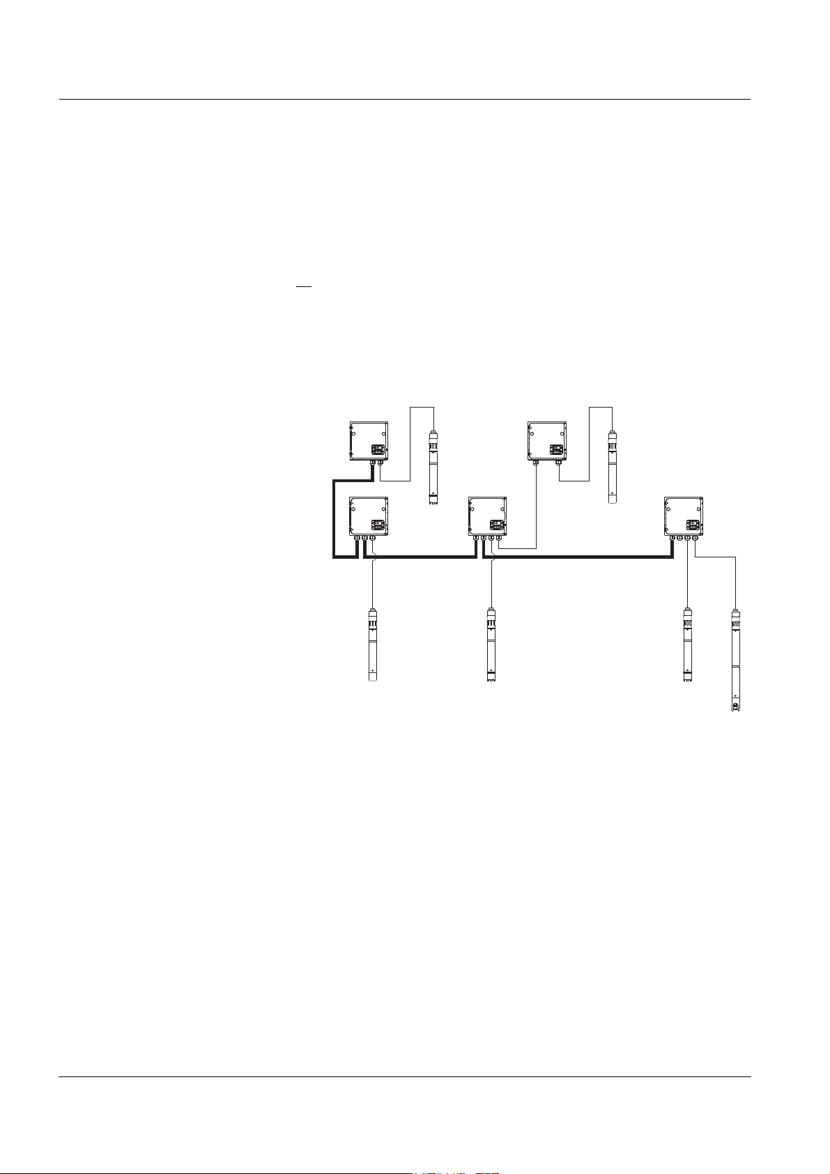
7.2 Application example for several radio links
ba76095e02 01/2013
Fig. 7-1 Example 3: Star-shaped structure - controller in the center
7 - 1
Page 44

Appendix: Installation instructions for several radio links MIQ/Blue PS
7.3 Power supply
Several MIQ/Blue PS
modules on an
IQ S
ENSORNET island
Compatibility with other
line power supply units
Example Problem:
If several MIQ/Blue PS modules are positioned on one IQ S
ENSORNET
island, only one of them can take over the power supply. All other MIQ/
Blue PS modules count as consumers in the power rating (power
requirement 0.6 W). Accordingly, only one MIQ/Blue PS module has to
be connected to the power supply.
If other power supply modules (e.g. MIQ/PS) are installed on the
IQ S
ENSORNET island, the line power supply units of all MIQ/Blue PS
modules are automatically inactive. Connecting the MIQ/Blue PS line
power supply units to a power supply remains ineffective here. In this
case, all MIQ/Blue PS modules are consumers with a power consumption of 0.6 W each in the power rating.
An IQ SENSORNET island should consist of the following compo-
nents plus two MIQ/Blue PS modules:
Component Power requirement
[W]
VisoTurb
ViSolid
SensoLyt
®
700 IQ 1.5
®
700 IQ 1.5
®
700 IQ 0.2
MIQ/CHV PLUS 1.0
MIQ/TC 2020 XT (docked from time to time) 3.0
In this example, both MIQ/Blue PS modules and the MIQ/CHV
PLUS should be mounted as a stack.
The IQ S
ENSORNET system should be supplied with 100 ...
240 V AC.
Solution/proceeding:
An MIQ/Blue PS module counts as a consumer with 0.6 W. In the
worst case, i. e. with a docked MIQ/TC 2020 XT, the power requirement of all components is 7.8 W. Power losses in cables do not have
to be taken into account due to the stack mounting.
Power rating: The calculated power requirement is greater than the
maximum power delivery of the MIQ/Blue PS line power supply unit.
Therefore, an additional power supply module has to be installed
(e.g. MIQ/PS).
New power rating: The second MIQ/Blue PS module has to be taken
into account as a consumer as well. Therefore, the power consumption is now 8.4 W. With an MIQ/PS power supply module (18 W),
there is still an energy reserve of 9.6 W for any future extensions.
7 - 2
ba76095e02 01/2013
Page 45

MIQ/Blue PS Contact Information
8 Contact Information
8.1 Ordering & Technical Support
Telephone
Fax
: (937) 767-9353 (orders)
Email
Mail: YSI Incorporated
Internet
When placing an order please have the following information available:
YSI account number (if available) Name and Phone Number
Model number or brief description Billing and shipping address
Quantity Purchase Order or Credit Card
: (800) 897-4151
(937) 767-7241
Monday through Friday, 8:00 AM to 5:00 PM ET
(937) 767-1058 (technical support)
: environmental@ysi.com
1725 Brannum Lane
Yellow Springs, OH 45387
USA
: www.ysi.com
ba76095e02 01/2013
8.2 Service Information
YSI has authorized service centers throughout the United States and
Internationally. For the nearest service center information, please visit
www.ysi.com
directly at 800-897-4151.
When returning a product for service, include the Product Return form
with cleaning certification. The form must be completely filled out for an
YSI Service Center to accept the instrument for service. The Product
Return form may be downloaded at www.ysi.com
‘Support‘ tab.
and click ‘Support’ or contact YSI Technical Support
and clicking on the
3
Page 46

Contact Information MIQ/Blue PS
4
ba76095e02 01/2013
Page 47

Page 48

1) The tissue in plants that brings water upward from the roots;
2) a leading global water technology company.
We're 12,500 people unified in a common purpose: creating innovative solutions
to meet our world's water needs. Developing new technologies that will improve
the way water is used, conserved, and re-used in the future is central to our work.
We move, treat, analyze, and return water to the environment, and we help people
use water efficiently, in their homes, buildings, factories and farms. In more than
150 countries, we have strong, long-standing relationships with customers who
know us for our powerful combination of leading product brands and applications
expertise, backed by a legacy of innovation.
For more information on how Xylem can help you, go to www.xyleminc.com
Xylem |' m|zīlə
YSI
1725 Brannum Lane
Yellow Springs, OH 45387
Tel: +1 937-767-7241; 800-765-4974
Fax: +1 937-767-1058
Email: environmental@ysi.com
Web: www.ysi.com
©Xylem Inc
 Loading...