

Page 1

YSI Environmental
YSI 556 MPS
Multi Probe System
Operations
Manual
Page 2

Page 3

Contents
1. Safety .........................................................................................................................1
1.1 General Information...........................................................................................1
2. General Information ................................................................................................6
2.1 Description.........................................................................................................6
2.2 Unpacking the Instrument..................................................................................7
2.3 Features of the YSI 556 Multi-Probe System....................................................8
2.4 Batteries.............................................................................................................9
2.5 Power On.........................................................................................................14
2.6 Setting Display Contrast..................................................................................14
2.7 Backlight..........................................................................................................15
2.8 General Screen Features ..................................................................................15
2.9 Keypad Use......................................................................................................16
2.10 Instrument Reset..............................................................................................17
2.11 Menu Flowchart...............................................................................................18
3. Probe Module..........................................................................................................18
3.1 Introduction......................................................................................................19
3.2 Unpacking the Probe Module..........................................................................19
3.3 Features of the YSI 5563 Probe Module .........................................................20
3.4 Preparing the Probe Module............................................................................20
3.5 Transport/Calibration Cup...............................................................................24
3.6 Instrument/Cable Connection..........................................................................25
4. Sensors.....................................................................................................................26
5. Report......................................................................................................................29
6. Calibrate..................................................................................................................32
6.1 Getting Ready to Calibrate ..............................................................................32
6.2 Calibration Procedures.....................................................................................35
6.3 Return to Factory Settings. ..............................................................................52
7. Run...........................................................................................................................54
7.1 Real-Time Data................................................................................................54
8. File............................................................................................................................55
8.1 Accessing the File Screen................................................................................55
8.2 Directory..........................................................................................................56
8.3 View File .........................................................................................................58
8.4 Upload to PC....................................................................................................59
8.5 File Memory ....................................................................................................63
8.6 Delete All Files................................................................................................64
YSI Incorporated YSI 556 MPS Page
i
Page 4

Contents
9. Logging....................................................................................................................66
9.1 Accessing the Logging Setup Screen ..............................................................66
9.2 Setting Logging Interval..................................................................................67
9.3 Storing Barometer Readings............................................................................67
9.4 Creating a Site List..........................................................................................68
9.5 Editing a Site List............................................................................................72
9.6 Logging Data Without a Site List....................................................................72
9.7 Logging Data with a Site List..........................................................................75
9.8 Adding Data to Existing Files .........................................................................77
10. System Setup...........................................................................................................79
10.1 Accessing the System Setup Screen ................................................................79
10.2 Language Setting.............................................................................................80
10.3 Date and Time Setup .......................................................................................80
10.4 Data Filter........................................................................................................82
10.5 Shutoff Time....................................................................................................84
10.6 Comma Radix..................................................................................................85
10.7 ID.....................................................................................................................85
10.8 GLP Filename..................................................................................................85
10.9 TDS Constant ..................................................................................................86
10.10 Barometer Units ..............................................................................................87
10.11 Calibrate Barometer ........................................................................................88
11. Maintenance............................................................................................................90
11.1 Sensor Care and Maintenance .........................................................................90
11.2 Upgrading YSI 556 MPS Software.................................................................96
12. Storage.....................................................................................................................99
12.1 General Recommendations for Short Term Storage........................................99
12.2 General Recommendations for Long Term Storage........................................99
13. Troubleshooting....................................................................................................102
14. Appendix A YSI 556 MPS Specifications...........................................................105
15. Appendix B Instrument Accessories...................................................................106
16. Appendix C Required Federal Communications Notice ..................................107
17. Appendix D Health Safety...................................................................................108
18. Appendix E Customer Service ............................................................................111
18.1 Ordering and Technical Support....................................................................111
18.2 YSI Authorized Service Centers....................................................................111
18.3 Cleaning Instructions.....................................................................................111
YSI 556 MPS YSI Incorporated
Page ii
Page 5

Contents
18.4 Packing Procedure.........................................................................................112
18.5 Warranty........................................................................................................113
19. Appendix F Ferrite Bead Installation.................................................................114
20. Appendix G EcoWatch.........................................................................................116
20.1 Installing EcoWatch for Windows.................................................................116
20.2 EcoWatch Tutorial.........................................................................................116
21. Appendix H Calibration Record Information ...................................................127
21.1 Viewing the Calibration Record (.glp) File ...................................................127
21.2 Uploading the Calibration Record (.glp) File................................................127
21.3 Understanding the Calibration Record (.glp) File..........................................127
YSI Incorporated YSI 556 MPS
Page iii
Page 6

Page 7
1. Safety
1.1 General Information
Read all safety information in this manual carefully before using the YSI
556 Multi-Probe System (MPS). Reagents that are used to calibrate and
check this instrument may be hazardous to your health. Take a moment to
review Appendix D Health and Safety.
WARNING
Warnings are used in this manual when misuse of the instrument could
result in death or serious injury to a person.
CAUTION
Cautions are used in this manual when misuse of the instrument could result
in mild or serious injury to a person and/or damage to equipment.
IMPORTANT SAFETY INSTRUCTIONS!
In essence, the most important safety rule for use of the YSI 556 MPS is to
utilize the instrument ONLY for purposes documented in this manual. This
is particularly true of the YSI 6117 rechargeable battery pack that contains
nickel metal hydride (NiMH) batteries. The user should be certain to read all
of the safety precautions outlined below before using the instrument.
Batteries
This instrument is powered by alkaline or optional nickel-metal hydride
batteries, which the user must remove and dispose of when the batteries no
longer power the instrument. Disposal requirements vary by country and
region, and users are expected to understand and follow the battery disposal
requirements for their specific locale.
The circuit board in this instrument contains a manganese dioxide lithium
"coin cell" battery that must be in place for continuity of power to memory
devices on the board. This battery is not user serviceable or replaceable.
YSI 556 MPS YSI Incorporated
Page 1
SAVE THESE INSTRUCTIONS!
Page 8

Safety Section 1
When appropriate, an authorized YSI service center will remove this battery
and properly dispose of it, per service and repair policies.
YSI Rechargeable Battery Pack Safety Information
Restrictions on Usage
1. Never dispose of the battery pack in a fire.
2. Do not attempt to disassemble the YSI 6117 battery pack
3. Do not tamper with any of the electronic components or the
batteries within the battery pack. Tampering with either the
electronic circuitry or the batteries will result in the voiding of the
warranty and the compromising of the system performance, but,
more importantly, can cause safety hazards which result from
overcharging such as overheating, venting of gas, and loss of
corrosive electrolyte.
4. Do not charge the battery pack outside the 0–40°C temperature
range.
5. Do not use or store the battery at high temperature, such as in strong
direct sunlight, in cars during hot weather, or directly in front of
heaters.
6. Do not expose the battery pack to water or allow the terminals to
become damp.
7. Avoid striking or dropping the battery pack. If the pack appears to
have sustained damage from these actions or malfunctions after an
impact or drop, the user should not attempt to repair the unit.
Instead, contact YSI Customer Service. Refer to Appendix E
Customer Service.
8. If the battery pack is removed from the YSI 556 MPS, do not store
it in pockets or packaging where metallic objects such as keys can
short between the positive and negative terminals.
Precautions for Users with Small Children.
Keep the battery pack out of reach of babies and small children.
Danger Notifications – Misuse creates a STRONG possibility of death or
serious injury.
YSI 556 MPS YSI Incorporated
Page 2
Page 9

Safety Section 1
FAILURE TO CAREFULLY OBSERVE THE FOLLOWING
PROCEDURES AND PRECAUTIONS CAN RESULT IN LEAKAGE
OF BATTERY FLUID, HEAT GENERATION, BURSTING, AND
SERIOUS PERSONAL INJURY.
1. Never dispose of the battery pack in a fire or in heat.
2. Never allow the positive and negative terminals of the battery pack to
become shorted or connected with electrically conductive materials.
When the battery pack has been removed from the YSI 556 MPS, store
it in a heavy plastic bag to prevent accidental shorting of the terminals.
3. Never disassemble the battery pack and do not tamper with any of the
electronic components or the batteries within the battery pack. The
battery pack is equipped with a variety of safety features. Accidental
deactivation of any of these safety features can cause a serious hazard to
the user.
4. The NiMH batteries in the battery pack contain a strong alkaline
solution (electrolyte). The alkaline solution is extremely corrosive and
will cause damage to skin or other tissues. If any fluid from the battery
pack comes in contact with a user’s eyes, immediately flush with clean
water and consult a physician immediately. The alkaline solution can
damage eyes and lead to permanent loss of eyesight.
Warning Notifications – Misuse creates a possibility of death or serious
injury
1. Do not allow the battery pack to contact freshwater, seawater, or other
oxidizing reagents that might cause rust and result in heat generation. If
a battery becomes rusted, the gas release vent may no longer operate and
this failure can result in bursting.
2. If electrolyte from the battery pack contacts the skin or clothing,
thoroughly wash the area immediately with clean water. The battery
fluid can irritate the skin.
Caution Notifications – Misuse creates a possibility of mild or serious
injury or damage to the equipment.
1. Do not strike or drop the battery pack. If any impact damage to the
battery pack is suspected, contact YSI Customer Service. Refer to
Appendix E Customer Service.
YSI Incorporated YSI 556 MPS
Page 3
Page 10

Safety Section 1
2. Store the battery pack out of reach of babies and small children.
3. Store the battery pack between the temperatures of -20 and 30°C.
4. Before using the battery pack, be sure to read the operation manual and
all precautions carefully. Then store this information carefully to use as
a reference when the need arises.
YSI 616 Cigarette Lighter Charger Safety Information
1. This section contains important safety and operating instructions for the
YSI 556 MPS cigarette lighter battery charger (YSI 616; RadioShack
Number 270-1533E). BE SURE TO SAVE THESE INSTRUCTIONS.
2. Before using the YSI 616 cigarette lighter charger, read all instructions
and cautionary markings on battery charger, battery pack, and YSI 556
MPS.
3. Charge the YSI 6117 battery pack with the YSI 616 cigarette lighter
charger ONLY when the YSI 6117 is installed in the YSI 556 MPS.
4. Do not expose charger to rain, moisture, or snow.
5. Use of an attachment not recommended or sold by the battery charger
manufacturer may result in a risk of fire, electric shock, or injury to
persons.
6. To reduce risk of damage to cigarette lighter and cord, pull by cigarette
lighter rather than cord when disconnecting charger.
7. Make sure that the cord is located so that it will not be stepped on,
tripped over, or otherwise subjected to damage or stress.
8. Do not operate charger with damaged cord or cigarette lighter connector
– replace it immediately.
9. Do not operate charger if it has received a sharp blow, been dropped, or
otherwise damaged in any way; contact YSI Customer Service. Refer to
Appendix E Customer Service.
10. Do not disassemble charger other than to change the fuse as instructed.
Replace the part or send it to YSI Product Service if repair is required
(refer to Appendix E Customer Service). Incorrect reassembly may result
in a risk of electric shock or fire.
YSI 556 MPS YSI Incorporated
Page 4
Page 11

Safety Section 1
11. To reduce risk of electric shock, unplug charger before attempting any
maintenance or cleaning. Turning off controls will not reduce this risk.
YSI 556 MPS Water Leakage Safety Information
The YSI 556 MPS has been tested and shown to comply with IP67 criterion,
i.e. submersion in 1 meter of water for 30 minutes with no leakage into
either the battery compartment or the main case. However, if the instrument
is submersed for periods of time in excess of 30 minutes, leakage may occur
with subsequent damage to the batteries, the rechargeable battery pack
circuitry, and/or the electronics in the main case.
If leakage into the battery compartment is observed when using alkaline C
cells, remove batteries, dispose of batteries properly, and dry the battery
compartment completely, ideally using compressed air. If corrosion is
present on the battery terminals, contact YSI Customer Service for
instructions. Refer to Appendix E Customer Service.
If leakage into the battery compartment is observed when using the YSI
rechargeable battery pack, remove the battery assembly and set aside to dry.
Return the battery pack to YSI Product Service for evaluation of possible
damage. Finally dry the battery compartment completely, ideally using
compressed air. If corrosion is present on the battery terminals, contact YSI
Customer Service for instructions. Refer to Appendix E Customer Service.
CAUTION: If water has contacted the rechargeable battery pack, do
not attempt to reuse it until it has been evaluated by YSI Product Service
(refer to Appendix E Customer Service). Failure to follow this precaution
can result in serious injury to the user.
If it is suspected that leakage into the main cavity of the case has occurred,
remove the batteries immediately and return the instrument to YSI Product
Service for damage assessment. Refer to Appendix E Customer Service.
CAUTION: Under no circumstances should the user attempt to open
the main case.
YSI Incorporated YSI 556 MPS
Page 5
Page 12

2. General Information
2.1 Description
The rugged and reliable YSI 556 MPS (Multi-Probe System) combines the
versatility of an easy-to-use, easy-to-read handheld unit with all the
functionality of a multi-parameter system. Featuring a waterproof, impactresistant case, the YSI 556 MPS simultaneously measures dissolved oxygen,
conductivity, temperature, and optional pH and ORP. A simple cellular
phone style keypad and large display make the instrument easy to use. The
YSI 556 MPS is compatible with YSI EcoWatch
software.
The YSI 556 MPS assists the user in conforming to Good Laboratory
Practice (GLP) standards which help ensure that quality control/quality
assurance methods are followed. Battery life is displayed with a fuel gauge,
and the user can choose standard alkaline batteries or an optional
rechargeable battery pack.
The 1.5 MB memory can store more than 49,000 data sets. Other options
include a flow cell and barometer. The internal barometer can be usercalibrated and displayed along with other data, used in dissolved oxygen
calibrations, and logged to memory for tracking changes in barometric
pressure.
TM
for WindowsTM
Features
• Waterproof -meets IP67 specifications
• Field-replaceable DO electrode module; pH and pH/ORP sensors
TM
• Compatible with EcoWatch
software
• Assists with Good Laboratory Practice Standards (GLP)
• Choice of DO membrane material for different applications
• Easy-to-use, screw-on cap DO membranes
• User-upgradeable software from YSI website
• Three-year warranty on the instrument; one-year on the probe
modules
• Available with 4,10, and 20 m cable lengths
• Stores over 49,000 data sets, time and date stamped
YSI 556 MPS YSI Incorporated
Page 6
for WindowsTM data analysis
Page 13

Probe Module Section 3
• Auto temperature compensating display contrast
• Optional barometer
• Optional rechargeable battery pack or standard alkaline batteries
2.2 Unpacking the Instrument
1. Remove the instrument from the shipping box. Note that the
probe module and sensors are shipped in a separate box and
will be unpacked later in Section 3.2 Unpacking the Probe
Module
NOTE: Do not discard any parts of supplies.
2. Use the packing list to ensure all items are present.
3. Visually inspect all components for damage.
NOTE: If any parts are missing or damaged, contact your
YSI Service Center immediately. Refer to Appendix E
Customer Service or www.ysi.com.
YSI Incorporated YSI 556 MPS
Page 7
Page 14
Probe Module Section 3
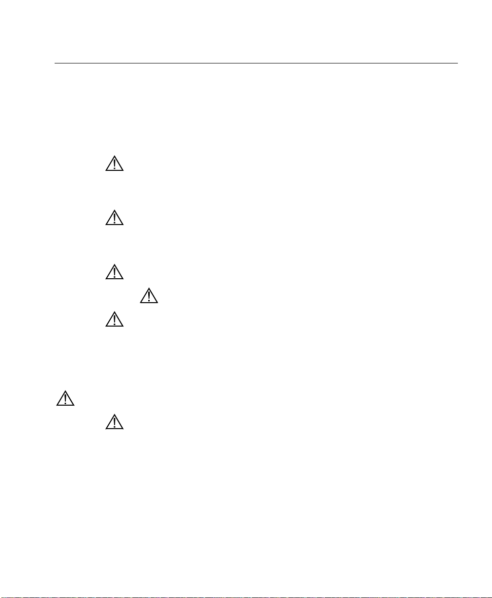
2.3 Features of the YSI 556 Multi-Probe System
On/Off Key
Arrow Keys
Escape Key
Display
Backlight
Key
Enter Key
Alpha/Numeric
Keys – Used to
enter letters and
numbers
Cable Connector
Figure 2.1 Front View of YSI 556 MPS
YSI 556 MPS YSI Incorporated
Page 8
Page 15
Probe Module Section 3
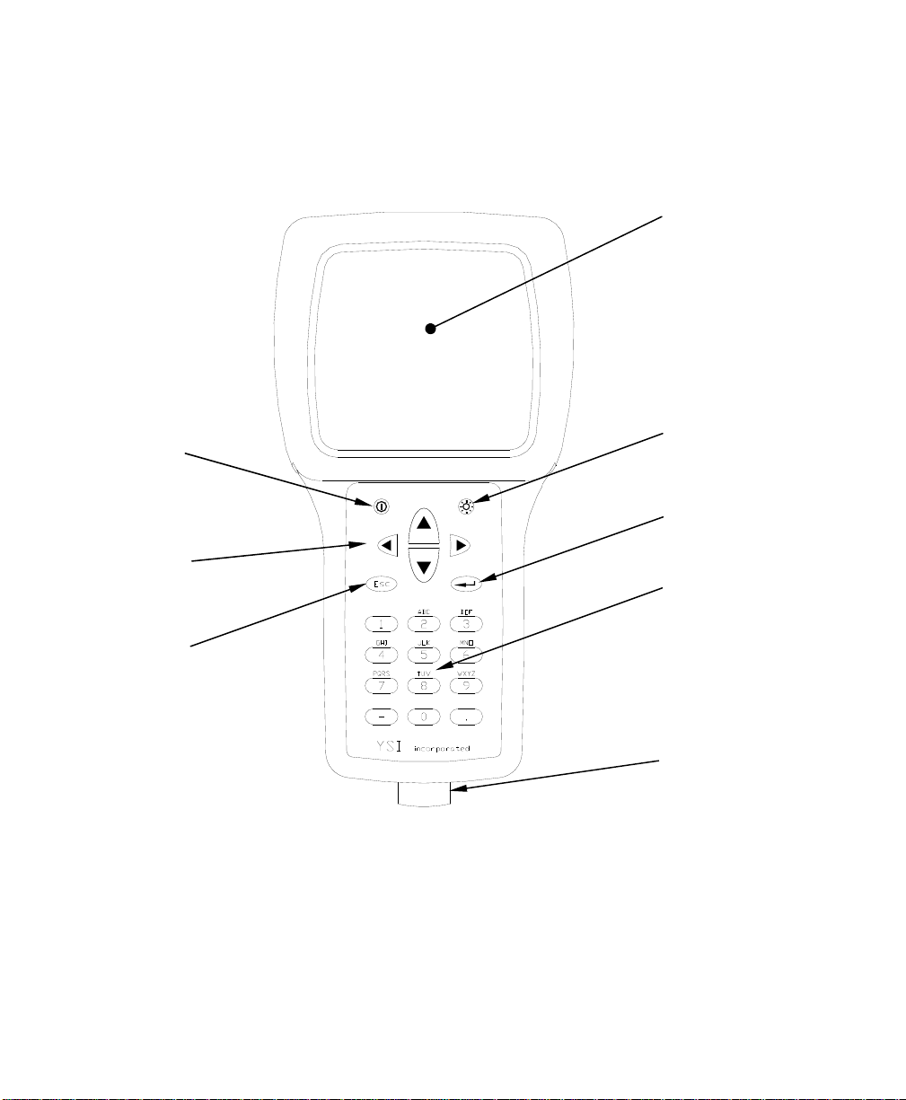
Barometer
Vent Patch
Accessory
Mounting
Holes
Lid
Battery Lid
Screws
Figure 2.2 Back View of YSI 556 MPS
2.4 Batteries
2.4.1 Battery Life
Standard Alkaline Batteries
With the standard battery configuration of 4 alkaline C cells, the YSI 556
MPS will operate continuously for approximately 180 hours. Assuming a
standard usage pattern when sampling of 3 hours of “on time” in a typical
day, the alkaline cells will last approximately 60 days.
Optional Rechargeable Battery Pack
When fully charged, the optional rechargeable battery pack will provide
approximately 50 hours of battery life.
YSI Incorporated YSI 556 MPS
Page 9
Page 16
Probe Module Section 3
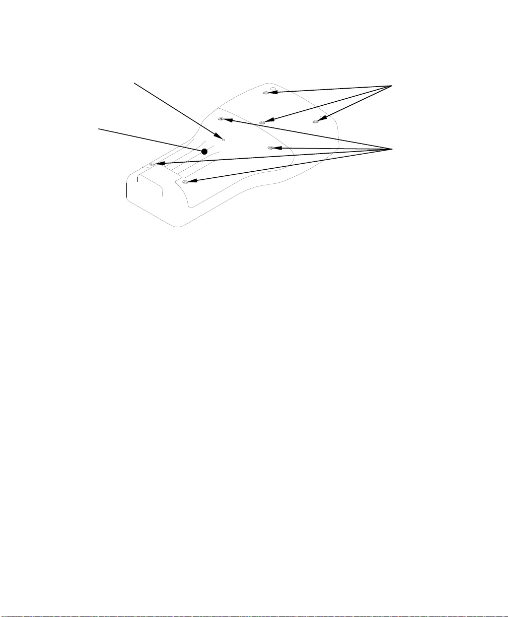
2.4.2 Inserting 4 C Batteries
Figure 2.1 Inserting C Cells
CAUTION: Install batteries properly to avoid damage to the
instrument.
1. Loosen the four screws in the battery lid on the back of the
instrument using any screwdriver.
2. Remove the battery lid.
3. Insert four C batteries between the clips following the polarity
(+ and -) labels on the bottom of the battery compartment.
4. Check gasket for proper placement on the battery lid.
5. Replace the battery lid and tighten the 4 screws securely and
evenly.
NOTE: Do not over-tighten the screws.
YSI 556 MPS YSI Incorporated
Page 10
Page 17
Probe Module Section 3
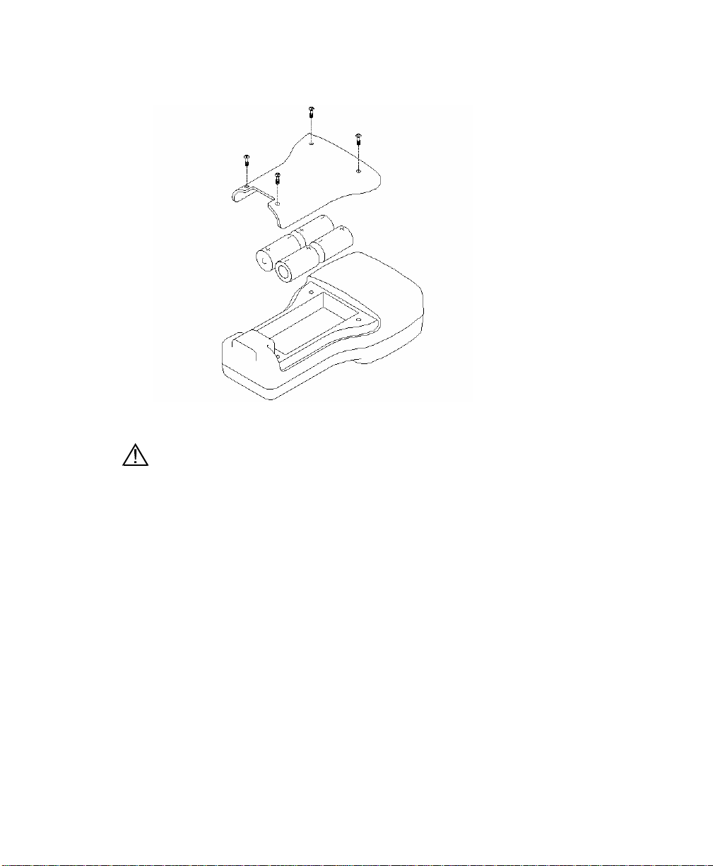
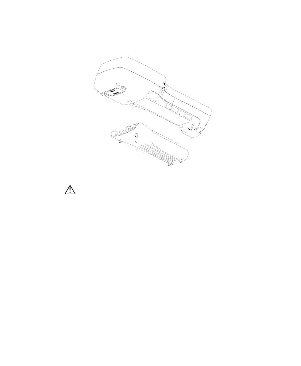
2.4.3 Inserting Optional Rechargeable Battery Pack
Figure 2.2 Inserting Battery Pack
CAUTION: Read all cautions and warning that come with the battery
pack before using the battery pack.
1. Loosen the four screws in the battery lid on the back of the
instrument using any screwdriver.
2. Remove the C battery lid and store for future use. Remove C
batteries, if installed.
3. Install the rechargeable battery pack and lid and tighten the 4
screws securely and evenly.
NOTE: Do not over tighten the screws.
YSI Incorporated YSI 556 MPS
Page 11
Page 18
Probe Module Section 3
)
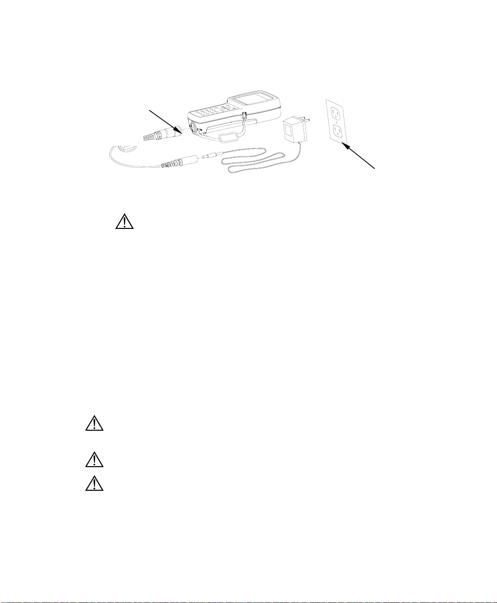
2.4.4 Charging the Optional Rechargeable Battery Pack
Charger Adapter cable
(YSI 6119)
Wall Power
Supply (YSI
Figure 2.3 Charging the Battery Pack
6114
CAUTION: Do not use or store the battery pack at extreme
temperatures such as in strong direct sunlight, in cars during hot
weather or close to heaters.
1. Install the rechargeable battery pack into the instrument as
described in Section 2.4.3 Inserting Optional Rechargeable
Battery Pack.
2. Attach the charger adapter cable (YSI 6119) to the instrument.
NOTE: Wall power supplies for use in countries outside the US and
Canada can be found in Appendix B Instrument Accessories.
3. Insert the barrel connector of the wall power supply into the
barrel of the adapter cable.
CAUTION: Do not charge the battery pack continuously for more than
48 hours.
CAUTION: Do not drop or expose to water.
CAUTION: Do no charge the battery pack at temperatures below 0°C
or above 40°C.
4. Plug the wall power supply into an AC power outlet for
approximately 2 hours to obtain an 80% to 90% charge for 6
hours to get a full charge.
YSI 556 MPS YSI Incorporated
Page 12
Page 19
Probe Module Section 3
NOTE: The battery pack can be recharged whether the instrument
is on or off.
2.4.5 Storing the Battery Pack
Remove the battery pack from the instrument when the
instrument will not be used for extended periods of time to
prevent over discharge of the battery pack.
Store the battery pack in a heavy plastic bag to prevent
accidental shorting of the terminals. Store between –20 and
30°C.
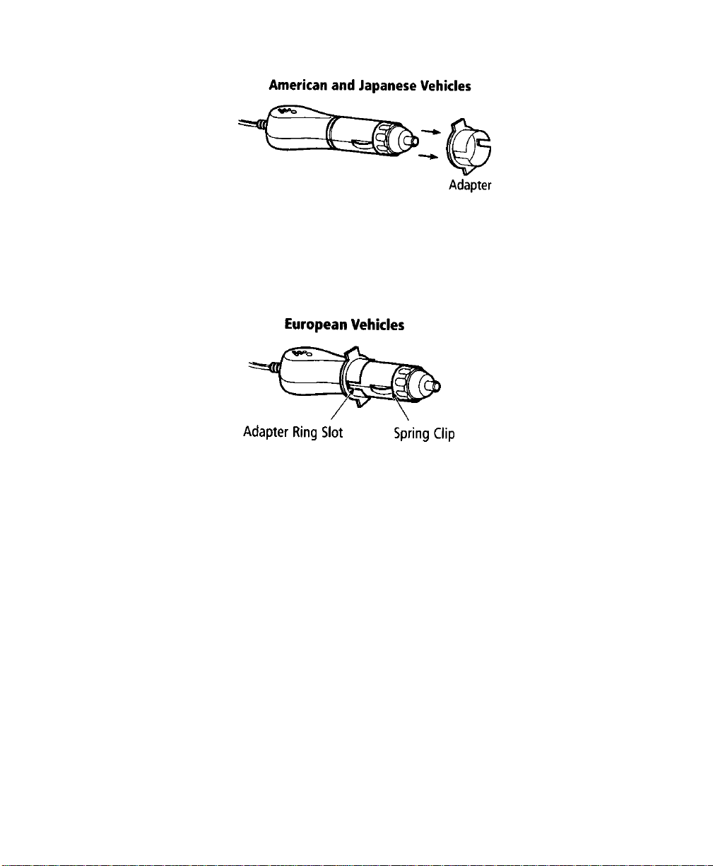
2.4.6 Optional Cigarette Lighter Charger
CAUTION: Read all warnings and cautions that come with the charger
before using the charger.
CAUTION: Only use cigarette lighter charger when rechargeable
battery pack is inserted into instrument.
CAUTION: Do not mishandle cigarette lighter charger. Do not expose
to moisture.
1. Plug the barrel connector of the cigarette lighter charger into
the mating end of the YSI 6119 Charger Adapter Cable.
2. Attach the MS-19 end of the YSI 6119 Charger Adapter
Cable to the instrument.
3. Make one of the following modifications to the other end of
the charger:
Slide the adapter ring off the plug to use the device with an
American or Japanese vehicle.
.
YSI Incorporated YSI 556 MPS
Page 13
Page 20
Probe Module Section 3
Figure 2.1 Charger Plug Adapter Use
Leave the adapter ring on the plug and position it so that the slots on
the adapter ring line up with the plug’s spring clips to use the device
on a European vehicle.
Figure 2.2 European Charger Plug Adapter Use
NOTE: If the charger stops working properly, refer to Section 13
Troubleshooting.
2.5 Power On
Press and release the on/off button in the upper left corner of the instrument
keypad to turn the instrument on or off. See Figure2.1 Front View of YSI
556 MPS.
2.6 Setting Display Contrast
The display contrast automatically compensates for temperature changes.
However, under extreme temperature conditions you may wish to optimize
the display by manual adjustment as follows:
YSI 556 MPS YSI Incorporated
Page 14
Page 21
Probe Module Section 3
1. Press and hold down the backlight key in the upper right
corner of the keypad and press the “up” arrow to increase
(darken) the contrast.
2. Press and hold down the backlight key in the upper right
corner of the keypad and press the “down” arrow to decrease
(lighten) the contrast.
2.7 Backlight
Press and release the backlight key in the upper right corner of the keypad
to turn the backlight on or off. See Figure 2.1 Front View of YSI 556 MPS.
NOTE: The backlight turns off automatically after two minutes of non-use.
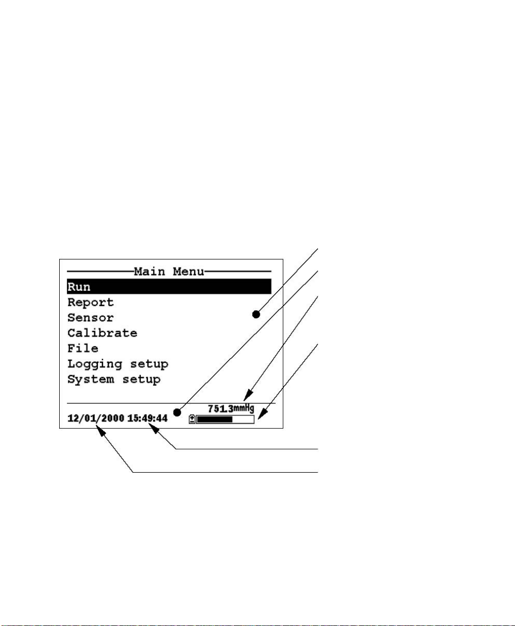
2.8 General Screen Features
Figure 2.4 Main Screen Menu
Main display
Status Bar
Barometer Reading (optional) –
Updated in real time, not
corrected to sea level
Battery Charge – NiMH label
indicates use of optional
rechargeable battery pack,
pulsing indicates that battery is
charging, flashing indicates
batteries almost exhausted.
Current Time
Current Date
YSI Incorporated YSI 556 MPS
Page 15
Page 22
Probe Module Section 3
–
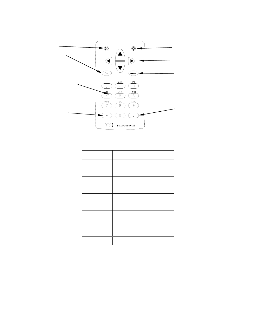
2.9 Keypad Use
On/Off key
Escape Key – Use
to return to
previous position
in menu
Alpha/Numeric Keys
Used to enter letters
and numbers
Minus/Hyphen (-)
Key
Figure 2.5 Keypad Features
KEY LETTER/NUMBER
1 1
2 ABC2abc3
3 DEF3def3
4 GHI4ghi4
5 JKL5jkl5
6 MNO6mno6
7 PQRS7pqrs7
8 TUV8tuv8
9 WXYZ9wxyz9
0 0
Backlight/Contrast
Arrow Keys
Enter Key
Period/Decimal
Point Key
Figure 2.6 Keypad Features
1. See Figure 2.10 Keypad Letters & Numbers and press the
appropriate key repeatedly until letter or number desired
appears in display.
YSI 556 MPS YSI Incorporated
Page 16
Page 23

Probe Module Section 3
NOTE: Press the key repeatedly in rapid succession to get to
the desired letter or number. If you pause for more than a
second, the cursor automatically scrolls to the right to prepare
for the next input.
EXAMPLE 1: Press the 6 key once and release to display an
uppercase “M”.
EXAMPLE 2: Press the 6 key four times and release to
display the number “6”.
EXAMPLE 3: Press the 6 key five times and stop to display a
lowercase “m”.
2. Press the left arrow key to go back and reenter a number or
setter that needs to be changed.
Press the Enter key when your entry is complete.
NOTE: The instrument software permits only numeric entries
in many instances, such as when setting the clock or entering
calibration parameters.
2.10 Instrument Reset
The YSI 556 MPS is characterized by sophisticated software that should
provide trouble-free operation. However, as with all high-capability
software packages, it is always possible that the user will encounter
circumstances in which the instrument does not respond to keypad entry. If
this occurs, the instrument function can easily be restored by removing and
then reapplying battery power. Simply remove either your C-cells or
rechargeable battery pack from the battery compartment, wait 30 seconds
and then replace the batteries. See Section 2.4 Batteries for battery
removal/reinstallation instructions.
YSI Incorporated YSI 556 MPS
Page 17
Page 24
Probe Module Section 3
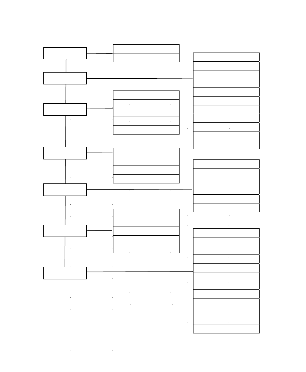
2.11 Menu Flowchart
Run
Report
Sensor
Calibrate
File
Logging Setup
System Setup
Log One Sample
Start Logging
Temperature
Conductivity
Dissolved Oxygen
pH
ORP
Condutivity
DO
pH
ORP
Interval
Use Site List
Store Barometer
Store Site Number
Edit Site List
Temperature
Specific Conductance
Conductivity
Resistivity
TDS
Salinity
DO % Saturation
DO mg/L
pH
pH mV
ORP
Directory
Upload to PC
Plot file
View file
File memory
Delete all files
Version
Language
Data & time
Data filter
Shut off time
Comma Radix
ID
Circuit board SN
GLP file name
TDS Constant
Barometer Units
Calibrate barometer
YSI 556 MPS YSI Incorporated
Page 18
Page 25

3. Probe Module
3.1 Introduction
The YSI 5563 Probe module is used for measuring dissolved oxygen,
temperature, conductivity, and optional pH and ORP. The probe module is
rugged, with the sensors enclosed in a heavy duty probe sensor guard with
attached sinking weight. A 4, 10 or 20 meter cable is directly connected to
the probe module body making it waterproof. An MS-19 connector at the
end of the cable makes the YSI 5563 fully compatible with the YSI 556
Multi-Probe System.
3.2 Unpacking the Probe Module
1. Remove the YSI 5563 Probe Module from the shipping
boxes.
NOTE: Do not discard any parts or supplies.
2. Use the packing list to ensure all items are present.
3. Visually inspect all components for damage.
NOTE: If any parts are missing or damaged, contact a YSI
representative immediately. Refer to: Appendix E Customer
Service o visit www.ysi.com.
YSI 556 MPS YSI Incorporated
Page 19
Page 26
Probe Module Section 3
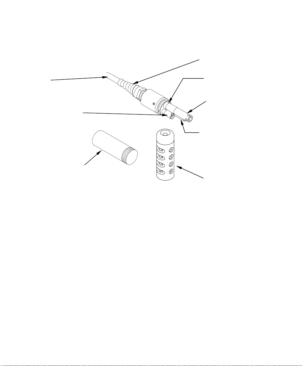
3.3 Features of the YSI 5563 Probe Module
Cable
Dissolved Oxygen
(DO) Probe
Transport/
Calibration Cup
Figure 3.1 Probe Module
3.4 Preparing the Probe Module
To prepare the probe module for calibration and operation, you need to
install the sensors into the connectors on the probe module bulkhead. In
addition to sensor installation, you need to install a new DO membrane cap.
Strain Relief
Metal Probe
Connector Nut
pH/ORP Probe
Conductivity/
Temperature
Probe
Probe Sensor Guard
3.4.1 Sensor Installation
Whenever you install, remove or replace a sensor, it is extremely important
that the entire probe module and all sensors be thoroughly dried prior to the
removal of a sensor or a sensor port plug. This will prevent water from
entering the port. Once you remove a sensor or plug, examine the connector
inside the probe module sensor port. If any moisture is present, use
compressed air to completely dry the connector. If the connector is
corroded, return the probe module to your YSI Distributor or directly to YSI
Customer Service. Refer to Appendix E Customer Service.
YSI 556 MPS YSI Incorporated
Page 20
Page 27
Probe Module Section 3
port
port
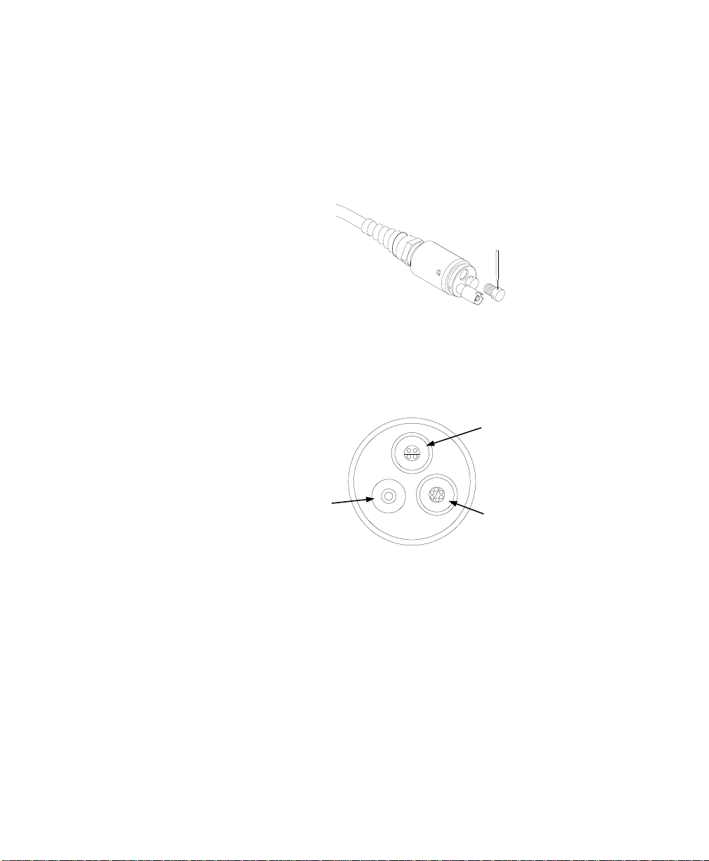
Conductivity/Temperature and pH, pH/ORP Sensor Installation
1. Unscrew and remove the probe sensor guard.
2. Using the sensor installation tool supplied in the YSI 5511
maintenance kit, unscrew and remove the sensor port plugs.
Figure 3.2 Port Plug Removal
3. Locate the port with the connector that corresponds to the
sensor that is to be installed.
pH or pH/ORP port
Dissolved Oxygen
Figure 3.3 Sensor Port Identification
4. Apply a thin coat of o-ring lubricant (supplied in the YSI
5511 maintenance kit) to the o-rings on the connector side of
the sensor (see Figure 3.4 O-ring Lubrication).
YSI Incorporated YSI 556 MPS
Conductivity/Temperature
Page 21
Page 28
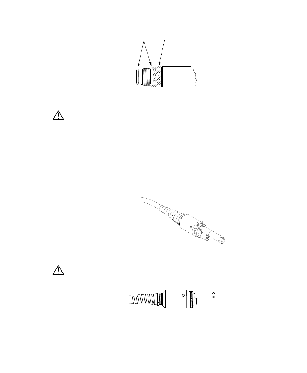
Probe Module Section 3
O-Rings
Sensor nut
Figure 3.4 O-ring Lubrication
CAUTION: Make sure that there are NO contaminants between the o-ring
and the sensor. Contaminants that are present under the o-ring may cause
the o-ring to leak.
5. Be sure the probe module sensor port is free of moisture and
then insert the sensor into the correct port. Gently rotate the
sensor until the two connectors align.
6. With the connectors aligned, screw down the sensor nut using
the sensor installation tool.
Figure 3.5 Sensor Installation
CAUTION: Do not cross thread the sensor nut. Tighten the nut until it is
flush with the face of the probe module bulkhead. Do not over tighten.
Figure 3.6 Bulkhead Seating
7. Repeat steps 3-6 for any other sensors.
YSI 556 MPS YSI Incorporated
Page 22
Page 29

Probe Module Section 3
8. Replace the probe sensor guard.
Dissolved Oxygen Sensor Installation
The YSI 5563 comes with the DO sensor already installed. Refer to Section
11.1.2 DO Sensor Replacement for instructions on installing the YSI 559
Replaceable DO Module Kit.
3.4.2 Membrane Cap Selection
The YSI 5563 is shipped with a YSI 5909 kit that contains membrane caps
made with 2 mil polyethylene (PE), a material which should be ideal for
most field applications of the 556. However, YSI also offers membrane caps
made with two other materials (1 mil polyethylene and 1 mil Teflon) which
some users may also prefer. All membranes available for the 556/5563
system provide comparable accuracy if used properly. The difference
between the two thicknesses of PE is found in the trade-off of flow
dependence and response time as described below. Teflon is offered because
some users may prefer to continue using the traditional membrane material
used by YSI. To avoid confusion, the membrane caps are color coded as
described below and can be ordered in kits as noted:
1 mil Teflon – Black Caps (Kit = YSI 5906)
1 mil Polyethylene (PE) – Yellow Caps (Kit = YSI 5908)
2 mil Polyethylene (PE) – Blue Caps (Kit = YSI 5909)
The 1 mil Teflon caps will offer traditional, reliable performance for most
dissolved oxygen applications. The 1 mil PE caps will provide a
significantly faster dissolved oxygen response (as long as your 556 Data
Filter is set correctly as described below in Sections 10.2 and 10.3.1) while
also giving readings which are significantly less flow dependent than the 1
mil Teflon caps. Finally, 2 mil PE caps will show a large reduction in flow
dependence over 1 mil Teflon while not significantly increasing the
response time. Generally, one of the PE caps is likely to provide better
performance for your application.
IMPORTANT: No matter which type of membrane cap you select, you
will have to confirm your selection in the 556 software from the Sensor
menu as described in Section 4 Sensors.
YSI Incorporated YSI 556 MPS
Page 23
Page 30

Probe Module Section 3
3.4.3 Membrane Cap Installation
NOTE: The YSI 5563 DO sensor (already installed in the probe module)
was shipped dry. A shipping membrane was installed to protect the
electrode. A new membrane cap must be installed before the first use.
1. Unscrew and remove the probe sensor guard.
2. Unscrew, remove, and discard the old membrane cap.
3. Thoroughly rinse the sensor tip with distilled water.
4. Prepare the electrolyte according to the directions on the
electrolyte solution bottle.
5. Hold the new membrane cap and fill it at least ½ full with the
electrolyte solution.
6. Screw the membrane cap onto the sensor moderately tight. A
small amount of electrolyte should overflow.
Caution: Do not touch the membrane surface.
7. Screw the probe sensor guard on moderately tight.
3.5 Transport/Calibration Cup
The YSI 5563 Probe module has been supplied with a convenient
transport/calibration cup. This cup is an ideal container for calibration of the
different sensors, minimizing the amount of solution needed. Refer to
Section 6 Calibrate.
YSI 556 MPS YSI Incorporated
Page 24
Page 31
Probe Module Section 3
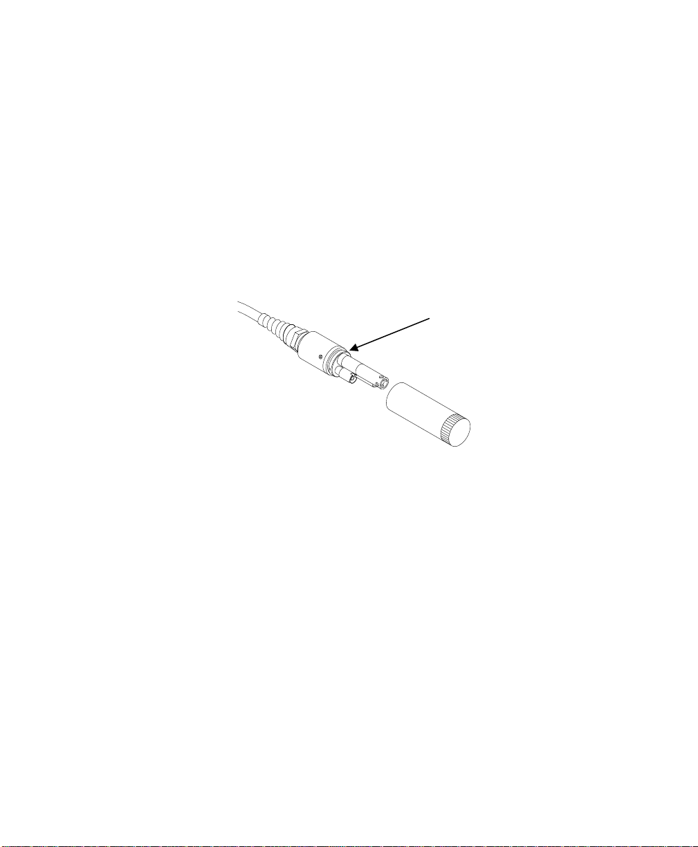
3.5.1 Transport/Calibration Cup Installation
1. Remove probe sensor guard, if already installed.
2. Ensure that an o-ring is installed in the o-ring groove on the
threaded end of the probe module body.
3. Screw the transport/calibration cup on the threaded end of the
probe module and securely tighten.
NOTE: Do not over tighten as this could cause damage to the
threaded portions.
Figure 3.7 Transport/Calibration Cup Instal l a ti o n
3.6 Instrument/Cable Connection
Attach the cable to the instrument as follows:
1. Line up the pins and guides on the cable with the holes and
indentations on the cable connector at the bottom of the YSI
556 instrument. See Figure 2.1 Front View of YSI 556 MPS.
2. Holding the cable firmly against the cable connector, turn the
locking mechanism clockwise until it snaps into place.
Remove the cable from the instrument by turning the cable
connector counterclockwise until the cable disengages from the
instrument.
O-ring
YSI Incorporated YSI 556 MPS
Page 25
Page 32

4. Sensors
The Sensors screen allows the user to enable or disable each of the sensors
and select which membrane material will be used for the dissolved oxygen
sensor. Disabled sensors will not be displayed on the screen in real time or
logged to files.
1. Press the On/off key to display the run screen.
2. Press the Escape key to display the main menu screen.
Figure 4.1 Main Menu Screen
3. Use the arrow keys to highlight the Sensor selection.
4. Press the Enter key to display the sensors enabled screen.
Enabled sensor
Disabled Sensor
YSI 556 MPS YSI Incorporated
Page 26
Page 33

Sensors Section 4
Figure 4.2 Sensors Enabled Screen Before DO Membrane Selection
A black dot to the left of a sensor indicates that sensor is enabled. Sensors
with an empty circle are disabled.
Highlight the “DO None” entry as shown above and press Enter to display
the membrane choice screen. Consult Section 3.4.2 Membrane Cap
Selection for information on the advantages of each type of membrane
material. Blue membrane caps using 2 mil polyethylene (PE) were shipped
with your YSI 5563 and are likely to be the best choice for most 556 field
applications.
Figure 4.3 Membrane Selection Screen
Highlight the desired membrane choice – in this case, 2 mil PE - and press
Enter to activate your selection with a dot to the left of the screen. Then
press Escape to return to the Sensor menu that now shows your DO
membrane selection.
YSI Incorporated YSI 556 MPS
Page 27
Page 34

Sensors Section 4
Figure 4.4 Sensors Enabled Screen After DO Membrane Selection
NOTE: The Temperature sensor cannot be disabled. Most
other sensors require temperature compensation for accurate
readings. In addition, the conductivity sensor must be
activated in order to obtain accurate dissolved oxygen mg/L
readings.
5. Use the arrow keys to highlight the sensor you want to
change, then press the Enter key to enable or disable it.
6. Repeat step 5 for each sensor you want to change.
7. Press the Escape key to return to the main menu screen.
YSI 556 MPS YSI Incorporated
Page 28
Page 35

N
5. Report
The Report Setup screen allows the user to select which sample parameters
and units the YSI 556 MPS will display on the screen. It does NOT
determine which parameters are logged to memory. Refer to Section 4
Sensors.
1. Press the On/off key to display the run screen.
2. Press the Escape key to display the main menu screen.
Figure 5.1 Main Menu
3. Use the arrow keys to highlight the Report selection.
4. Press the Enter key to display the report setup screen.
Selected for
display
OT selected
for display
YSI 556 MPS YSI Incorporated
Page 29
Page 36

Report Section 5
Figure 5.2 Report Setup Screen
NOTE: A black dot to the left of a parameter indicates that
parameter is selected for display. Parameters with an empty
circle will not be displayed.
NOTE: You may have to scroll down past the bottom of the
screen to see all the parameters.
5. Use the arrow keys to highlight the parameter you want to
change, then press the Enter key. If you can't find the
parameter you want, even after scrolling down past the
bottom of the screen, the sensor used for that parameter is
disabled. Refer to Section 4 Sensors.
6. If you selected Temperature, Specific Conductivity,
Conductivity, Resistance or Total Dissolved Solids, the Units
screen will appear.
Figure 5.3 Units Screen
7. Use the arrow keys to select the units desired, then press the
Enter key to return to the report setup screen.
8. Repeat steps 5 and 6 for each parameter you want to change.
YSI 556 MPS YSI Incorporated
Page 30
Page 37

Report Section 5
NOTE: Specific Conductance (temperature compensated
conductivity) is notated on the Run screen with a small ‘c’
after the units of measure.
All parameters may be enabled at the same time.
Figure 5.4 All Parameters Displayed
9. Press the Escape key to return to the Main menu screen.
YSI Incorporated YSI 556 MPS
Page 31
Page 38

6. Calibrate
All of the sensors, except temperature, require periodic calibration to assure
high performance. You will find specific calibration procedures for all
sensors that require calibration in the following sections. If a sensor listed is
not installed in your probe module, skip that section and proceed to the next
sensor until the calibration is complete.
CAUTION: Reagents that are used to calibrate and check this instrument
may be hazardous to your health. Take a moment to review Appendix D
Health and Safety. Some calibration standard solutions may require special
handling.
6.1 Getting Ready to Calibrate
6.1.1 Containers Needed to Calibrate the Probe Module
The transport/calibration cup that comes with your probe module serves as a
calibration chamber for all calibrations and minimizes the volume of
calibration reagents required.
Instead of the transport/calibration cup, you may use laboratory glassware to
perform calibrations. If you do not use the transport/calibration cup that is
designed for the probe module, you are cautioned to do the following:
9 Perform all calibrations with the Probe Sensor Guard installed.
This protects the sensors from possible physical damage.
9 Use a ring stand and clamp to secure the probe module body to
prevent the module from falling over. Most laboratory
glassware has convex bottoms.
9 Ensure that all sensors are i mmersed in calibration solutions.
Many of the calibrations factor in readings from other sensors
(e.g., temperature sensor). The top vent hole of the conductivity
sensor must also be immersed during some calibrations.
YSI 556 MPS YSI Incorporated
Page 32
Page 39

Calibrate Section 6
6.1.2 Calibration Tips
1. If you use the Transport/Calibration Cup for dissolved oxygen
(DO) calibration, make certain to loosen the seal to allow
pressure equilibration before calibration. The DO calibration
is a water-saturated air calibration.
2. When calibrating pH, always calibrate with buffer 7 first,
regardless if performing a 1, 2, or 3 point calibration
3. The key to successful calibration is to ensure that the sensors
are completely submersed when calibration values are
entered. Use recommended volumes when performing
calibrations.
4. For maximum accuracy, use a small amount of previously
used calibration solution to pre-rinse the probe module. You
may wish to save old calibration standards for this purpose.
5. Fill a bucket with ambient temperature water to rinse the
probe module between calibration solutions.
6. Have several clean, absorbent paper towels or cotton cloths
available to dry the probe module between rinses and
calibration solutions. Shake the excess rinse water off of the
probe module, especially when the probe sensor guard is
installed. Dry off the outside of the probe module and probe
sensor guard. Making sure that the probe module is dry
reduces carry-over contamination of calibrator solutions and
increases the accuracy of the calibration.
7. If you are using laboratory glassware for calibration, you do
not need to remove the probe sensor guard to rinse and dry the
sensors between calibration solutions. The inaccuracy
resulting from simply rinsing the sensor compartment and
drying the outside of the guard is minimal.
8. If you are using laboratory glassware, remove the stainless
steel weight from the bottom of the probe sensor guard by
turning the weight counterclockwise. When the weight is
removed, the calibration solutions have access to the sensors
YSI Incorporated YSI 556 MPS
Page 33
Page 40

Section 6 Calibrate
without displacing a lot of fluid. This also reduces the amount
of liquid that is carried between calibrations.
9. Make certain that port plugs are installed in all ports where
sensors are not installed. It is extremely important to keep
these electrical connectors dry.
6.1.3 Recommended Volumes
Follow these instructions to use the transport/calibration cup for calibration
procedures.
9 Ensure that an o-ring is installed in the o-ring groove of the
transport/calibration cup bottom cap, and that the bottom cap is
securely tightened.
NOTE: Do not over-tighten as this could cause damage to the
threaded portions.
9 Remove the probe sensor guard, if it is installed.
9 Remove the o-ring, if installed, from the probe module and
inspect the installed o-ring on the probe module for obvious
defects and, if necessary, replace it with the extra o-ring
supplied.
9 Some calibrat ions can be accomplished with the probe module
upright or upside down. A separate clamp and stand, such as a
ring stand, is required to support the probe module in the upside
down position.
9 To calibrate, follow the procedures in the next section,
Calibration Procedures. The approximate volumes of the
reagents are specified below for both the upright and upside
down orientations.
9 When using the Transport/Calibration Cup for dissolved oxygen
% saturation calibration, make certain that the vessel is vented
to the atmosphere by loosening the bottom cap or cup assembly
and that approximately 1/8 inch (3 cm) of water is present in the
cup.
YSI 556 MPS YSI Incorporated
Page 34
Page 41

Calibrate Section 6
Sensor to Calibrate Upright Upside Down
Conductivity 55ml 55ml
pH/ORP 30ml 60ml
Table 6.1 Calibration Volumes
6.2 Calibration Procedures
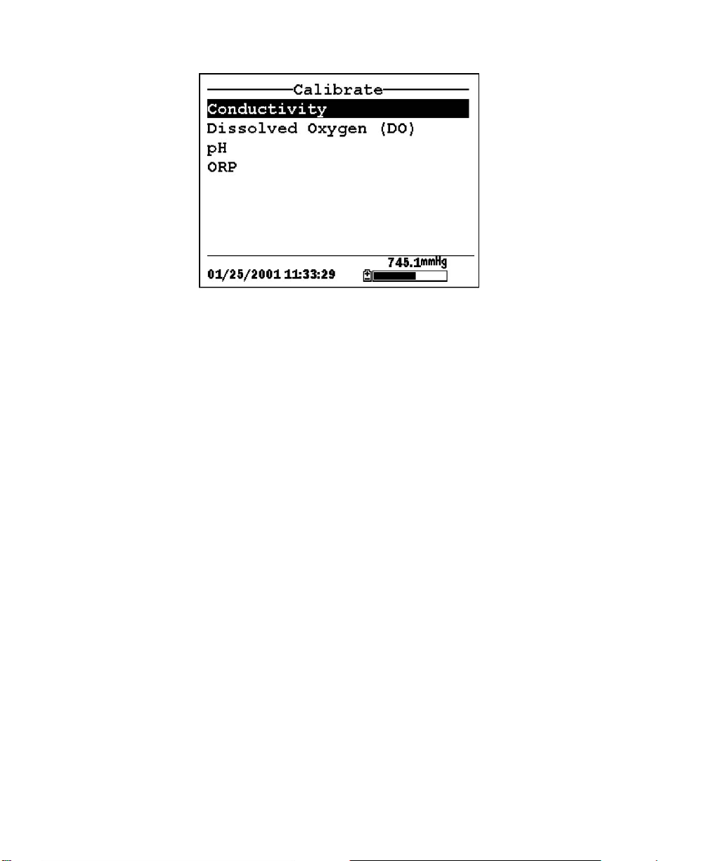
6.2.1 Accessing the Calibrate Screen
1. Press the On/off key to display the run screen.
2. Press the Escape key to display the main menu screen.
3. Use the arrow keys to highlight the Calibrate selection.
Figure 6.1 Main Menu
4. Press the Enter key. The Calibrate screen will be displayed.
YSI Incorporated YSI 556 MPS
Page 35
Page 42
Section 6 Calibrate
Figure 6.2 Calibrate Screen
6.2.2 Conductivity Calibration
This procedure calibrates specific conductance (recommended),
conductivity and salinity. Calibrating any one option automatically
calibrates the other two.
1. Go to the calibrate screen as described in Section
6.2.1Accessing the Calibrate Screen..
2. Use the arrow keys to highlight the Conductivity selection.
See Figure 6.2 Calibrate Screen.
3. Press Enter. The Conductivity Calibration Screen is
displayed.
YSI 556 MPS YSI Incorporated
Page 36
Page 43

Calibrate Section 6
Figure 6.3 Conductivity Calibration Selection Screen
4. Use the arrow keys to highlight the Specific Conductance
selection.
5. Press Enter. The Conductivity Calibration Entry Screen is
displayed.
Figure 6.4 Conductivity Calibration Selection Screen
6. Place the correct amount of conductivity standard (see Table
6.1 Calibration Volumes) into a clean, dry or pre-rinsed
transport/calibration cup.
YSI Incorporated YSI 556 MPS
Page 37
Page 44

Section 6 Calibrate
WARNING: Calibration reagents may be hazardous to your
health. See Appendix D Health and Safety for more
information.
NOTE: For maximum accuracy, the conductivity standard
you choose should be within the same conductivity range as
the samples you are preparing to measure. However, we do
not recommend using standards less than 1 mS/cm. For
example:
9 For fresh water use a 1 mS/cm conductivity standard.
9 For brackish water use a 10 mS/cm conductivity standard.
9 For seawater use a 50 mS/cm conductivity standard.
NOTE: Before proceeding, ensure that the sensor is as dry as
possible. Ideally, rinse the conductivity sensor with a small
amount of standard that can be discarded. Be certain that you
avoid cross-contamination of solutions. Make certain that
there are no salt deposits around the oxygen and pH/ORP
sensors, particularly if you are employing standards of low
conductivity.
7. Carefully immerse the sensor end of the probe module into
the solution.
8. Gently rotate and/or move the probe module up and down to
remove any bubbles from the conductivity cell.
NOTE: The sensor must be completely immersed past its vent
hole. Using the recommended volumes from Table 6.1
Calibration Volumes, should ensure that the vent hole is
covered.
9. Screw the transport/calibration cup on the threaded end of the
probe module and securely tighten.
NOTE: Do not over tighten as this could cause damage to the
threaded portions.
YSI 556 MPS YSI Incorporated
Page 38
Page 45
Calibrate Section 6
10. Use the keypad to enter the calibration value of the
standard you are using.
NOTE: Be sure to enter the value in mS/cm at 25°C.
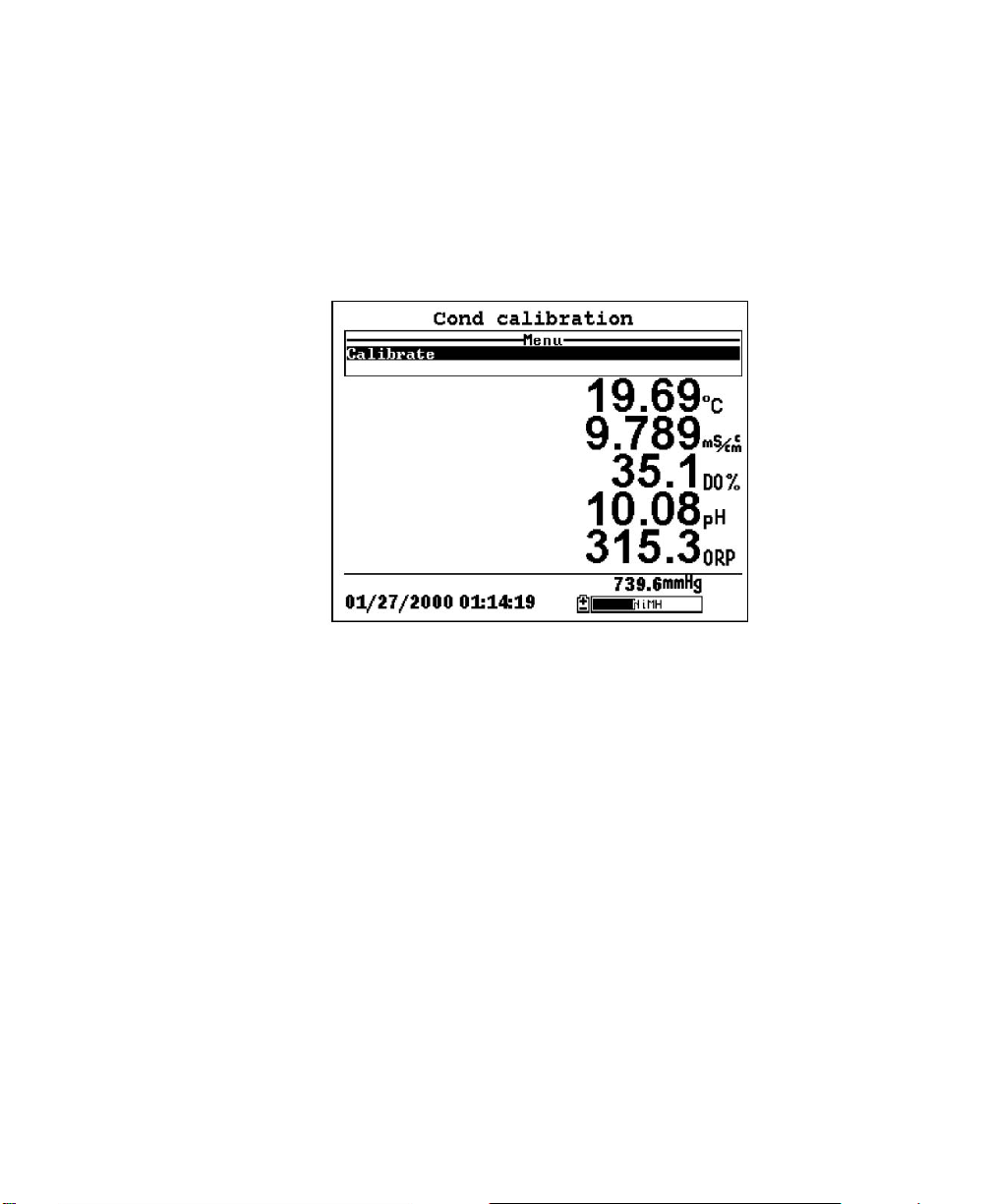
11. Press Enter. The Conductivity Calibration Screen is
displayed.
Figure 6.5 Conductivity Calibration Screen
12. Allow at least one minute for temperature equilibration before
proceeding. The current values of all enabled sensors will
appear on the screen and will change with time as they
stabilize.
13. Observe the reading under Specific Conductance. When the
reading shows no significant change for approximately 30
seconds, press Enter. The screen will indicate that the
calibration has been accepted and prompt you to press Enter
again to Continue.
YSI Incorporated YSI 556 MPS
Page 39
Page 46
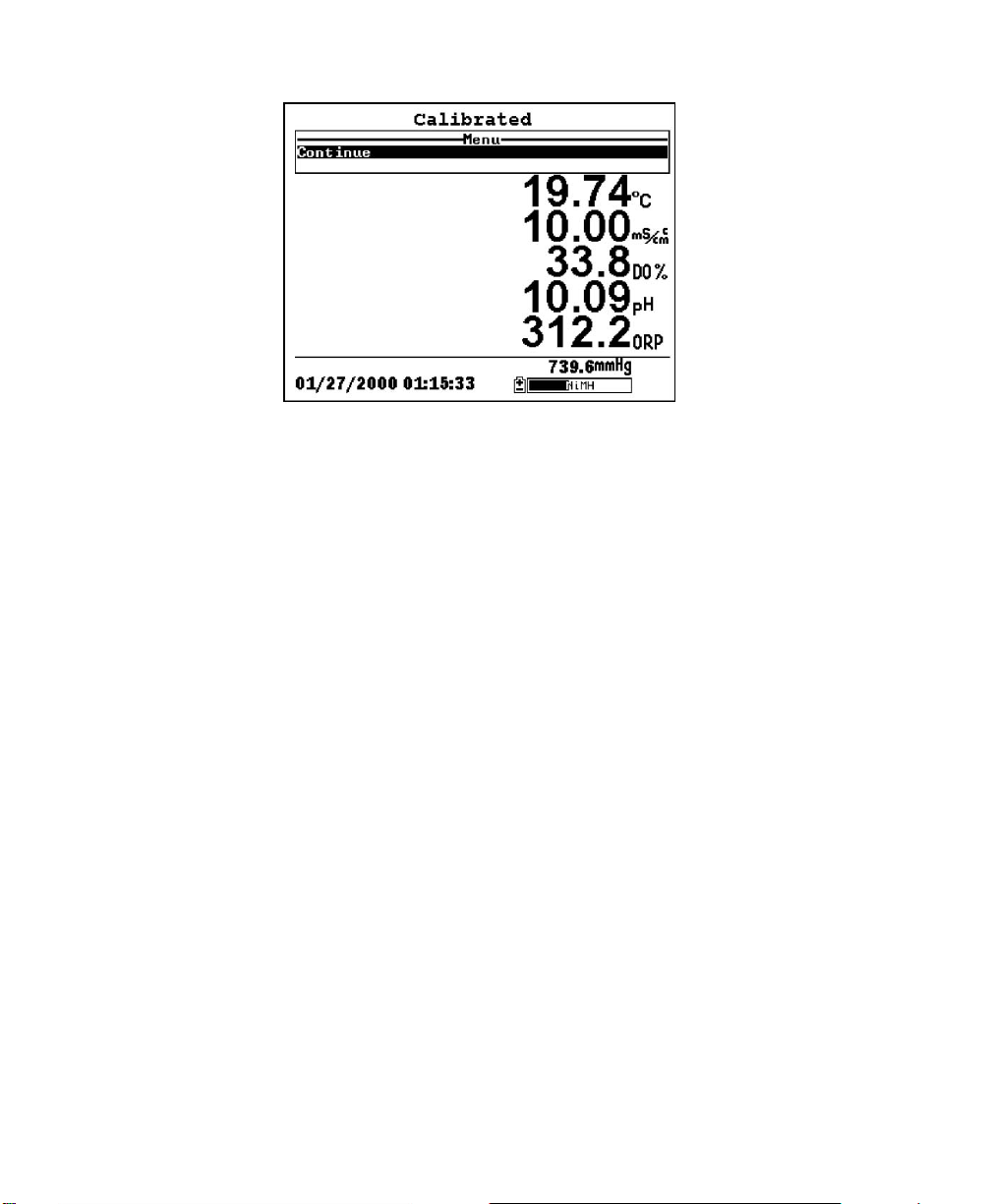
Section 6 Calibrate
Figure 6.6 Calibrated
14. Press Enter. This returns you to the Conductivity Calibrate
Selection Screen, See Figure 6.3 Conductivity Calibration
Selection Screen..
15. Press Escape to return to the calibrate menu. See Figure 6.2
Calibrate Screen .
16. Rinse the probe module and sensors in tap or purified water
and dry.
6.2.3 Dissolved Oxygen Calibration
This procedure calibrates dissolved oxygen. Calibrating any one option (%
or mg/L) automatically calibrates the other.
1. Go to the calibrate screen as described in Section 6.2.1
Accessing the Calibrate Screen.
NOTE: The instrument must be on for at least 10 - 15
minutes to polarize the DO sensor before calibrating.
2. Use the arrow keys to highlight the Dissolved Oxygen
selection. See Figure 6.2 Calibrate Screen.
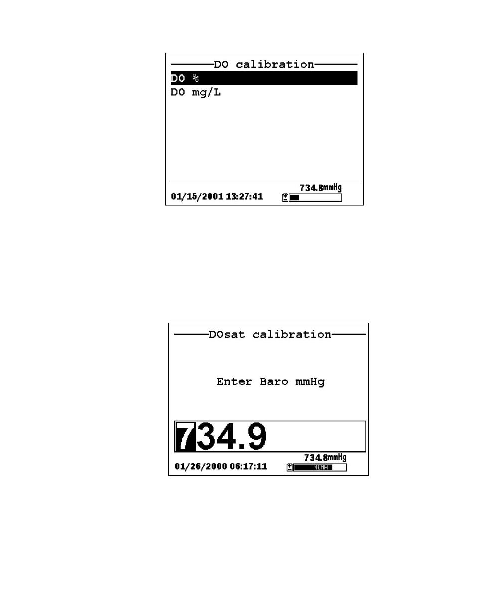
3. Press Enter. The dissolved oxygen calibration screen is
displayed.
YSI 556 MPS YSI Incorporated
Page 40
Page 47
Calibrate Section 6
Figure 6.7 DO Calibration Screen
DO Calibration in % Saturation
1. Use the arrow keys to highlight the DO% selection.
2. Press Enter. The DO Barometric Pressure Entry Screen is
displayed.
Figure 6.8 DO Barometric Pressure Entry Screen
3. Place approximately 3 mm (1/8 inch) of water in the bottom
of the transport/calibration cup.
4. Place the probe module into the transport/calibration cup.
YSI Incorporated YSI 556 MPS
Page 41
Page 48

Section 6 Calibrate
NOTE: Make sure that the DO and temperature sensors are
not immersed in the water.
5. Engage only 1 or 2 threads of the transport/calibration cup to
ensure the DO sensor is vented to the atmosphere.
6. Use the keypad to enter the current local barometric pressure.
NOTE: If the unit has the optional barometer, no entry is
required.
NOTE: Barometer readings that appear in meteorological
reports are generally corrected to sea level and must be
uncorrected before use (refer to Section 10.10 Calibrate
Barometer, Step 2).
7. Press Enter. The DO% saturation calibration screen is
displayed.
Figure 6.9 DO Sat Calibration Screen
8. Allow approximately ten minutes for the air in the
transport/calibration cup to become water saturated and for
the temperature to equilibrate before proceeding.
YSI 556 MPS YSI Incorporated
Page 42
Page 49

Calibrate Section 6
9. Observe the reading under DO %. When the reading shows no
significant change for approximately 30 seconds, press Enter.
The screen will indicate that the calibration has been accepted
and prompt you to press Enter again to Continue. See Figure
6.6 Calibrated.
10. Press Enter. This returns you to the DO calibration screen,
See Figure 6.7 DO Calibration Screen.
11. Press Escape to return to the calibrate menu. See Figure 6.2
Calibrate Screen.
12. Rinse the probe module and sensors in tap or purified water
and dry.
DO Calibration in mg/L
DO calibration in mg/L is carried out in a water sample which has a known
concentration of dissolved oxygen (usually determined by a Winkler
titration).
1. Go to the DO calibrate screen as described in Section 6.2.3
Dissolved Oxygen Calibration, steps 1 through 3.
2. Use the arrow keys to highlight the DO mg/L selection.
3. Press Enter. The DO mg/L Entry Screen is displayed.
YSI Incorporated YSI 556 MPS
Page 43
Page 50

Section 6 Calibrate
Figure 6.10 DO mg/L Entry Screen
4. Place the probe module in water with a known DO
concentration.
NOTE: Be sure to completely immerse all the sensors.
5. Use the keypad to enter the known DO concentration of the
water.
6. Press Enter. The Dissolved Oxygen mg/L Calibration Screen
is displayed.
Figure 6.11 DO mg/L Calibration Screen
YSI 556 MPS YSI Incorporated
Page 44
Page 51

Calibrate Section 6
7. Stir the water with a stir bar, or by rapidly moving the probe
module, to provide fresh sample to the DO sensor.
8. Allow at least one minute for temperature equilibration before
proceeding. The current values of all enabled sensors will
appear on the screen and will change with time as they
stabilize.
9. Observe the DO mg/L reading, when the reading is stable
(shows no significant change for approximately 30 seconds),
press Enter. The screen will indicate that the calibration has
been accepted and prompt you to press Enter again to
Continue.
10. Press Enter. This returns you to the DO calibration screen.
See Figure 6.7 DO Calibration Screen.
11. Press Escape to return to the calibrate menu. See Figure 6.2
Calibrate Screen.
12. Rinse the probe module and sensors in tap or purified water
and dry.
6.2.4 pH Calibration
1. Go to the calibrate screen as described in Section 6.2.1
Accessing the Calibrate Screen.
2. Use the arrow keys to highlight the pH selection. See Figure
6.2 Calibrate Screen.
3. Press Enter. The pH calibration screen is displayed.
YSI Incorporated YSI 556 MPS
Page 45
Page 52

Section 6 Calibrate
Figure 6.12 pH Calibration Screen
¾ Select the 1-point option only if you are adjusting a previous
calibration. If a 2-point or 3-point calibration has been
performed previously, you can adjust the calibration by carrying
out a one point calibration. The procedure for this calibration is
the same as for a 2-point calibration, but the software will
prompt you to select only one pH buffer.
¾ Select the 2-point option to calibrate the pH sensor using only
two calibration standards. Use this option if the media being
monitored is known to be either basic or acidic. For example, if
the pH of a pond is known to vary between 5.5 and 7, a twopoint calibration with pH 7 and pH 4 buffers is sufficient. A
three point calibration with an additional pH 10 buffer will not
increase the accuracy of this measurement since the pH is not
within this higher range.
¾ Select the 3-point option to calibrate the pH sensor using three
calibration solutions. In this procedure, the pH sensor is
calibrated with a pH 7 buffer and two additional buffers. The 3point calibration method assures maximum accuracy when the
pH of the media to be monitored cannot be anticipated. The
procedure for this calibration is the same as for a 2-point
calibration, but the software will prompt you to select a third pH
buffer.
4. Use the arrow keys to highlight the 2-point selection.
YSI 556 MPS YSI Incorporated
Page 46
Page 53

Calibrate Section 6
5. Press Enter. The pH Entry Screen is displayed.
Figure 6.13 pH Entry Screen
6. Place the correct amount (see Table 6.1 Calibration Volumes)
of pH buffer into a clean, dry or pre-rinsed
transport/calibration cup.
NOTE: Always calibrate with buffer 7 first, regardless if
performing a 1, 2, or 3 point calibration.
WARNING: Calibration reagents may be hazardous to your
health. See Appendix D Health and Safety for more information.
NOTE: For maximum accuracy, the pH buffers you choose
should be within the same pH range as the water you are
preparing to sample.
NOTE: Before proceeding, ensure that the sensor is as dry as
possible. Ideally, rinse the pH sensor with a small amount of
buffer that can be discarded. Be certain that you avoid crosscontamination of buffers with other solutions.
7. Carefully immerse the sensor end of the probe module into
the solution.
8. Gently rotate and/or move the probe module up and down to
remove any bubbles from the pH sensor.
YSI Incorporated YSI 556 MPS
Page 47
Page 54

Section 6 Calibrate
NOTE: The sensor must be completely immersed. Using the
recommended volumes from Table 6.1 Calibration Volumes,
should ensure that the sensor is covered.
9. Screw the transport/calibration cup on the threaded end of the
probe module and securely tighten
NOTE: Do not over tighten as this could cause damage to the
threaded portions.
10. Use the keypad to enter the calibration value of the buffer you
are using at the current temperature.
NOTE: pH vs. temperature values are printed on the labels of
all YSI pH buffers.
11. Press Enter. The pH calibration screen is displayed.
Figure 6.14 pH Calibration Screen
12. Allow at least one minute for temperature equilibration before
proceeding. The current values of all enabled sensors will
appear on the screen and will change with time as they
stabilize.
13. Observe the reading under pH, when the reading shows no
significant change for approximately 30 seconds, press Enter.
YSI 556 MPS YSI Incorporated
Page 48
Page 55

Calibrate Section 6
The screen will indicate that the calibration has been accepted
and prompt you to press Enter again to Continue.
14. Press Enter. This returns you to the specified pH Calibration
Screen, See Figure 6.13 pH Entry Screen.
15. Rinse the probe module, transport/calibration cup and sensors
in tap or purified water and dry.
16. Repeat steps 6 through 13 above using a second pH buffer.
17. Press Enter. This returns you to the pH Calibration Screen,
See Figure 6.12 pH Calibration Screen.
18. Press Escape to return to the calibrate menu. See Figure 6.2
Calibrate Screen.
19. Rinse the probe module and sensors in tap or purified water
and dry.
6.2.5 ORP Calibration
1. Go to the calibrate screen as described in Section 6.2.1
Accessing the Calibrate Screen.
2. Use the arrow keys to highlight the ORP selection. See Figure
6.2 Calibrate Screen..
3. Press Enter. The ORP calibration screen is displayed.
YSI Incorporated YSI 556 MPS
Page 49
Page 56

Section 6 Calibrate
Figure 6.15 Specified ORP Calibration Screen
4. Place the correct amount (see Table 6.1 Calibration Volumes)
of a known ORP solution (we recommend Zobell solution)
into a clean, dry or pre-rinsed transport/calibration cup.
WARNING: Calibration reagents may be hazardous to your
health. See Appendix D Health and Safety for more information.
NOTE: Before proceeding, ensure that the sensor is as dry as
possible. Ideally, rinse the ORP sensor with a small amount of
solution that can be discarded. Be certain that you avoid crosscontamination with other solutions.
5. Carefully immerse the sensor end of the probe module into
the solution.
6. Gently rotate and/or move the probe module up and down to
remove any bubbles from the ORP sensor.
NOTE: The sensor must be completely immersed. Using the
recommended volumes from Table 6.1 Calibration Volumes
should ensure that the sensor is covered.
7. Screw the transport/calibration cup on the threaded end of
the probe module and securely tighten.
NOTE: Do not over tighten as this could cause damage to the
threaded portions.
YSI 556 MPS YSI Incorporated
Page 50
Page 57

Calibrate Section 6
8. Use the keypad to enter the correct value of the calibration
solution you are using at the current temperature. Refer to
Table 6.2 Zobell Solution Values.
Temperature °C Zobell Solution Value, mV
-5 270.0
0 263.5
5 257.0
10 250.5
15 244.0
20 237.5
25 231.0
30 224.5
35 218.0
40 211.5
45 205.0
50 198.5
Table 6.2 Zobell Solution Values
9. Press Enter. The ORP calibration screen is displayed.
Figure 6.16 DO Cal Screen
10. Allow at least one minute for temperature equilibration before
proceeding. The current values of all enabled sensors will
appear on the screen and will change with time as they
stabilize.
NOTE: Verify that the temperature reading matches the value
you used in Table 6.2 Zobell Solution Values.
YSI Incorporated YSI 556 MPS
Page 51
Page 58

Section 6 Calibrate
11. Observe the reading under ORP, when the reading shows no
significant change for approximately 30 seconds, press Enter.
The screen will indicate that the calibration has been accepted
and prompt you to press Enter again to Continue.
12. Press Enter. This returns you to the Calibrate Screen. See
Figure 6.2 Calibrate Screen.
13. Rinse the probe module and sensors in tap or purified water
and dry.
6.3 Return to Factory Settings.
1. Go to the calibrate screen as described in Section 6.2.1
Accessing the Calibrate Screen.
2. Use the arrow keys to highlight the Conductivity selection.
See Figure 6.2 Calibrate Screen.
NOTE: We will use the Conductivity sensor as an example;
however, this process will work for any sensor.
3. Press Enter. The Conductivity Calibration Selection Screen is
displayed. See Figure 6.3 Conductivity Calibration Selection
Screen.
4. Use the arrow keys to highlight the Specific Conductance
selection.
5. Press Enter. The Conductivity Calibration Entry Screen is
displayed. See Figure 6.4 Conductivity Calibration Entry
Screen.
6. Press and hold the Enter key down and press the Escape key.
YSI 556 MPS YSI Incorporated
Page 52
Page 59

Calibrate Section 6
Figure 6.17 ORP Calibration Screen
7. Use the arrow keys to highlight the YES selection.
CAUTION: This returns a sensor to the factory settings. For
example, in selecting to return specific conductance to the
factory setting, salinity and conductivity will automatically
return to their factory settings.
8. Press Enter. This returns you to the Conductivity Calibrate
Selection Screen, See Figure 6.3 Conductivity Calibration
Selection Screen. .
9. Press Escape to return to the calibrate menu. See Figure 6.2
Calibrate Screen.
YSI Incorporated YSI 556 MPS
Page 53
Page 60
7. Run
The Run screen displays data from the sensors in real-time and allows the
user to log sample data to memory for later analysis. Refer to Section 9
Logging for details on logging sample data.
7.1 Real-Time Data
NOTE: Before measuring samples you must prepare the probe module
(refer to Section 3.4 Preparing the Probe Module), attach the probe module
to the instrument (refer to Section 3.6 Instrument/Cable Connection) and
calibrate the sensors (refer to Section 6 Calibrate).
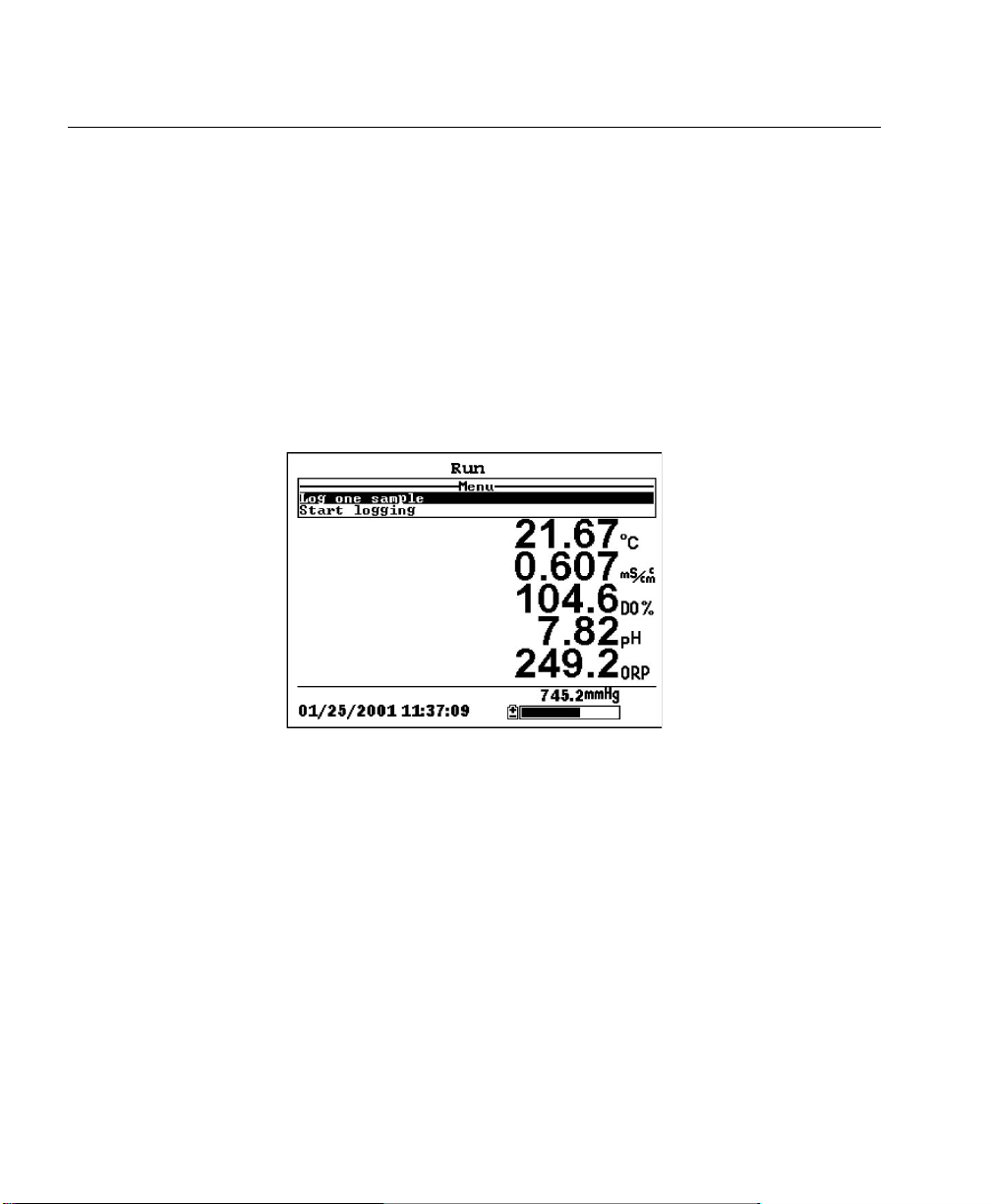
OR select Run from the main menu to display the run screen.
1. Press the On/off key.
Figure 7.1 Run Screen
2. Make sure the probe sensor guard is installed.
3. Place the probe module in the sample. Be sure to completely
immerse all the sensors.
4. Rapidly move the probe module through the sample to
provide fresh sample to the DO sensor.
5. Watch the readings on the display until they are stable.
6. Refer to Section 9 Logging for instructions on logging sample
data.
YSI 556 MPS YSI Incorporated
Page 54
Page 61

8. File
The File menu allows the user to view, upload or delete sample data and
calibration record files stored in the YSI 556 MPS.
8.1 Accessing the File Screen
1. Press the On/off key to display the run screen.
2. Press the Escape key to display the main menu screen.
Figure 8.1 Main Menu Screen
3. Use the arrow keys to highlight the File selection.
4. Press the Enter key. The file screen is displayed.
YSI 556 MPS YSI Incorporated
Page 55
Page 62

Section 8 File
Figure 8.2 File Screen
8.2 Directory
1. Go to the file screen as described in Section 8.1 Accessing the
File Screen.
2. Use the arrow keys to highlight the Directory selection. See
Figure 8.2 File Screen.
3. Press the Enter key. The file list screen is displayed.
NOTE: Files are listed in the order in which they are logged to memory.
Sample Data files have the file extension .dat, while Calibration Record
files have the file extension .glp.
YSI 556 MPS YSI Incorporated
Page 56
Page 63

File Section 8
Figure 8.3 File List Screen
4. Use the arrow keys to highlight a file.
5. Press the Enter key. The file details screen is displayed.
Figure 8.4 File Details Screen
6. Press the Enter key to view the file data. Refer to Section
8.3 View File for details.
7. Press the Escape key repeatedly to return to the main menu
screen.
YSI Incorporated YSI 556 MPS
Page 57
Page 64

Section 8 File
8.3 View File
1. Go to the file screen as described in Section 8.1 Accessing the
File Screen. See Figure 8.2 File Screen.
2. Use the arrow keys to highlight the View file selection.
3. Press the Enter key. A list of files is displayed. See Figure 8.3
File List Screen.
4. Use the arrow keys to highlight an individual file.
NOTE: You may have to scroll down to see all the files.
5. Press the Enter key. The file data is displayed with the file
name at t8e top of the display.
NOTE: If no file name was specified, the data is stored under
the default name NONAME1.dat.
Figure 8.5 File Data Screen
6. Use the arrow keys to scroll horizontally and/or vertically to
view all the data.
7. Press the Escape key repeatedly to return to the main menu
screen.
YSI 556 MPS YSI Incorporated
Page 58
Page 65

File Section 8
8.4 Upload to PC
EcoWatch™ for Windows™ must be used as the PC software interface to
the YSI 556 MPS. Refer to Appendix G EcoWatch for more information.
EcoWatch for Windows® is available at no cost via a download from the
YSI Web Site (www.ysi.com) or by contacting YSI Customer Support.
Refer to Appendix E Customer Service.
8.4.1 Upload Setup
1. Disconnect the YSI 5563 Probe Module from the YSI 556
MPS instrument.
2. Connect the YSI 556 MPS to a serial (Comm) port of your
computer via the 655173 PC Interface cable as shown in the
following diagram:
556 MPS
Computer with
EcoWatch for
Windows
Installed
655173 PC
Interface Cable
DE-9 PC Serial Port
Figure 8.2 Computer/Instrument Interface
3. Open EcoWatch for Windows on your computer.
NOTE: See Appendix G EcoWatch for installation
instructions.
4. Click on the sonde/probe icon
YSI Incorporated YSI 556 MPS
in the upper toolbar.
Page 59
Page 66

Section 8 File
5. Set the Comm port number to match the port the YSI 556
MPS is connected to. After this setup procedure, the following
screen will be present on your PC monitor:
8.4.2 Uploading a .DAT File
1. Setup the instrument as described in Section 8.4.1 Upload
Setup.
2. Go to the YSI 556 MPS file screen as described in Section 8.1
Accessing the File Screen.
3. Use the arrow keys to highlight the Upload to PC selection.
See Figure 8.2 File Screen.
4. Press the Enter key. The file list screen is displayed. See
Figure 8.3 File List Screen.
5. Use the arrow keys to highlight the DAT file that you wish to
transfer and press Enter, both the YSI 556 MPS and PC
displays show the progress of the file transfer.
YSI 556 MPS YSI Incorporated
Page 60
Page 67

File Section 8
Figure 8.3 File Transfer Progress Screen
NOTE: After transfer, the file will be located in the
C:\ECOWWIN\DATA folder of your PC, designated with a
.DAT extension.
6. After the file transfer is complete, close the terminal window
(small window on the PC) by clicking on the “X” at its upper
right corner.
7. Press the Escape key on the YSI 556 MPS repeatedly to return
YSI Incorporated YSI 556 MPS
Page 61
Page 68

Section 8 File
to the main menu screen.
8.4.3 Uploading a Calibration Record (.glp) File
For more information on the calibration record, refer to Appendix H
Calibration Record Information.
1. Setup up the instrument as described in Section 8.4.1 Upload
Setup.
2. Go to the YSI 556 MPS file screen as described in Section
3. Use the arrow keys to highlight the Upload to PC selection.
See Figure 8.2 File Screen.
4. Press the Enter key. The file list screen is displayed. See
Figure 8.3 File List Screen.
5. Use the arrow keys to highlight the calibration record file that
you wish to transfer and press Enter.
6. You will then be given a choice of uploading the file in three
formats; Binary, Comma & “” Delimited, and ASCII Text.
NOTE: The binary format is reserved for future YSI software
packages.
7. Choose an option and press Enter, both the YSI 556 and PC
displays show the progress of the file transfer.
NOTE: After transfer, the file will be located in the
C:\ECOWWIN\DATA folder of your PC, designated with the
appropriate file extension.
NOTE: To view the Calibration Record data after upload,
simply open the .txt file in a general text editor such as
Wordpad or Notepad.
8. After the file transfer is complete, close the terminal window
(small window on the PC) by clicking on the “X” at its upper
right corner.
YSI 556 MPS YSI Incorporated
Page 62
Page 69

File Section 8
9. Press the Escape key repeatedly to return to the main menu
screen.
8.5 File Memory
1. Go to the file screen as described in Section 8.1 Accessing the
File Screen.
2. Use the arrow keys to highlight the File memory selection.
See Figure 8.2 File Screen.
3. Press the Enter key. The file bytes used screen is displayed.
Figure 8.4 File Bytes Used Screen
4. The amount of free memory is listed in line 4 of the file bytes
used screen.
NOTE: If the amount of free memory is low, it may be time
to delete all files (after first uploading all data to a PC). Refer
to Section 8.6 Delete All Files.
5. Press the Escape key repeatedly to return to the main menu
screen.
YSI Incorporated YSI 556 MPS
Page 63
Page 70

Section 8 File
8.6 Delete All Files
NOTE: It is not possible to delete individual files in order to
free up memory. The only way to free up memory is to delete
ALL files present. Take care to transfer all files to your
computer (refer to Section 8.4 Upload to PC) before deleting
them.
1. Go to the file screen as described in Section 8.1 Accessing the
File Screen.
2. Use the arrow keys to highlight the Delete all files selection.
See Figure 8.2 File Screen.
3. Press the Enter key. The Delete all Files screen is displayed.
Figure 8.5 Delete All Files Screen
4. Use the arrow keys to highlight the Delete selection.
5. Press the Enter key.
YSI 556 MPS YSI Incorporated
Page 64
Page 71

File Section 8
Figure 8.10 Deleting
The progress of file deletion is displayed in bar graph format.
NOTE: Deleting all files in the directory will not change any information in
the site list.
6. Press the Escape key repeatedly to return to the main menu
screen.
YSI Incorporated YSI 556 MPS
Page 65
Page 72

9. Logging
9.1 Accessing the Logging Setup Screen
1. Press the On/off key to display the run screen.
2. Press the Escape key to display the main menu screen.
Figure 9.1 Main Menu
3. Use the arrow keys to highlight the Logging setup selection.
4. Press the Enter key. The logging setup screen is displayed.
Figure 9.2 Setup Screen
YSI 556 MPS YSI Incorporated
Page 66
Page 73

Logging Section 9
9.2 Setting Logging Interval
Follow steps below to set the interval for logging a data stream.
NOTE: If you do not specify an interval, the instrument will use a default
interval setting of 1 second.
NOTE: It is not necessary to set a logging interval when logging a single
sample.
1. Go to the logging setup screen as described in Section 9.1
Accessing the Logging Setup Screen.
2. Use the keypad to enter an interval between 1 second and 15
minutes. Refer to Section 2.9 Keypad Use.
NOTE: The interval field has hour, minute and second entry
fields. Any entry over 1 hour will change automatically to a
15-minute setting.
3. Press the Enter key. The data stream interval is set.
4. Press the Escape key repeatedly to return to the main menu
screen.
9.3 Storing Barometer Readings
NOTE: The Store barometer option is only available on
instruments that are equipped with the optional barometer.
1. Go to the logging setup screen as described in Section 9.1
Accessing the Logging Setup Screen.
2. Use the arrow keys to highlight the Store barometer
selection. See Figure 9.2 Logging Setup Screen.
3. Press the Enter key until a check mark is entered in the box
next to the store barometer selection if you want to log
barometric readings.
YSI Incorporated YSI 556 MPS
Page 67
Page 74

Section 9 Logging
OR press the Enter key until the box next to the barometer
selection is empty if you do not want to log barometric
readings.
Figure 9.3 Store Barometer
4. Press the Escape key repeatedly to return to the main menu
screen.
9.4 Creating a Site List
The site list option allows you to define file and site descriptions in the
office or laboratory before moving to field logging studies. This is usually
more convenient than entering the information at the site and is particularly
valuable if you are visiting certain sites on a regular basis. The following
section describes how to set up site lists which contain entries designated
“Site Descriptions” that will be instantly available to the user in the field to
facilitate the logging of data with pre-established naming of files and sites.
There are two kinds of Site Descriptions available for use in Site lists:
• Site Descriptions associated with applications where data from a single
site is always logged to a single file. This type is referred to as a “SingleSite Description” and is characterized by two parameters – a file name and a
site name. Files logged to YSI 556 MPS memory under a Single-Site
Description will be characterized primarily by the file name, but will also
have the Site name attached, so that it is viewable in either the YSI 556
MPS File directory or in EcoWatch for Windows after upload to a PC
• Site Descriptions associated with applications where data from multiple
sites are logged to a single file. This type is referred to as a “Multi-site
Description” and is characterized by three parameters – a file name, a site
name, and a site number. Files logged to YSI 556 MPS memory under a
YSI 556 MPS YSI Incorporated
Page 68
Page 75

Logging Section 9
t
N
Multi-site Description are characterized by a file name, but not a site name,
since multiple sites are involved. However, each data point has a Site
Number attached to it so that the user can easily determine the sampling site
when viewing the data from the YSI 556 MPS File menu or processing the
data in EcoWatch for Windows after upload to a PC.
Figure 9.4 Single-Site Descriptions
Site Lis
Single-Site Descriptions
with Different File
ames
Site List
Multi-Site
Descriptions
with the Same
File Name
Figure 9.5 Multiple-Site Descriptions
NOTE: Site lists containing Single Site Descriptions are usually input with
the designation Store Site Number INACTIVE in the YSI 556 MPS
Logging setup menu. Thus, no site numbers appear in the first Site list
example. Conversely, Site lists containing Multi-Site Descriptions MUST
be input with the Store Site Number selection ACTIVE as shown in the
second example.
YSI Incorporated YSI 556 MPS
Page 69
Page 76

Section 9 Logging
To create a site list:
1. Go to the logging setup screen as described in Section 9.1
Accessing the Logging Setup Screen.
2. Use the arrow keys to highlight the Use site list selection.
3. Press the Enter key. A check mark is entered in the box next
to the use site list selection and two new entries appear on the
logging setup screen. See Figure 9.6 Logging Setup Screen.
Figure 9.6 Logging Setup Screen
4. Use the arrow keys to highlight the Store site number
selection.
5. If you are creating Multi-Site Descriptions (which require that
the site number be stored in your data files), press the Enter
key until a check mark appears in the box next to the store site
number selection.
OR Press the Enter key until the box next to the store site number selection
is empty, to create Single-Site Descriptions. The site name will be stored in
the header of your data files.
6. Use the arrow keys to highlight the Edit site list selection.
7. Press the Enter key. The edit site list screen is displayed. See
Figure 9.7 Edit Site List Screen. The Filename field is ready
for input.
YSI 556 MPS YSI Incorporated
Page 70
Page 77

Logging Section 9
Figure 9.7 Edit Site List Screen
8. Use the keypad to enter a filename up to 8 characters in
length. Refer to Section 2.9 Keypad Use.
9. Press the Enter key. The cursor moves to the right for the
entry of a Site name.
10. Use the keypad to enter a site name up to 11 characters in
length. Refer to Section 2.9 Keypad Use.
NOTE: If the store site number selection is not checked, skip
to Step 13.
11. Press the Enter key. The cursor moves to the site number
entry position.
12. Use the keypad to enter a site number up to 7 characters in
length. Refer to Section 2.9 Keypad Use.
13. Press Enter. The cursor moves to the next filename entry
position.
14. Repeat Steps 8 to 13 until all filenames and sites have been
entered.
15. Press Escape repeatedly to return to the main menu screen.
YSI Incorporated YSI 556 MPS
Page 71
Page 78
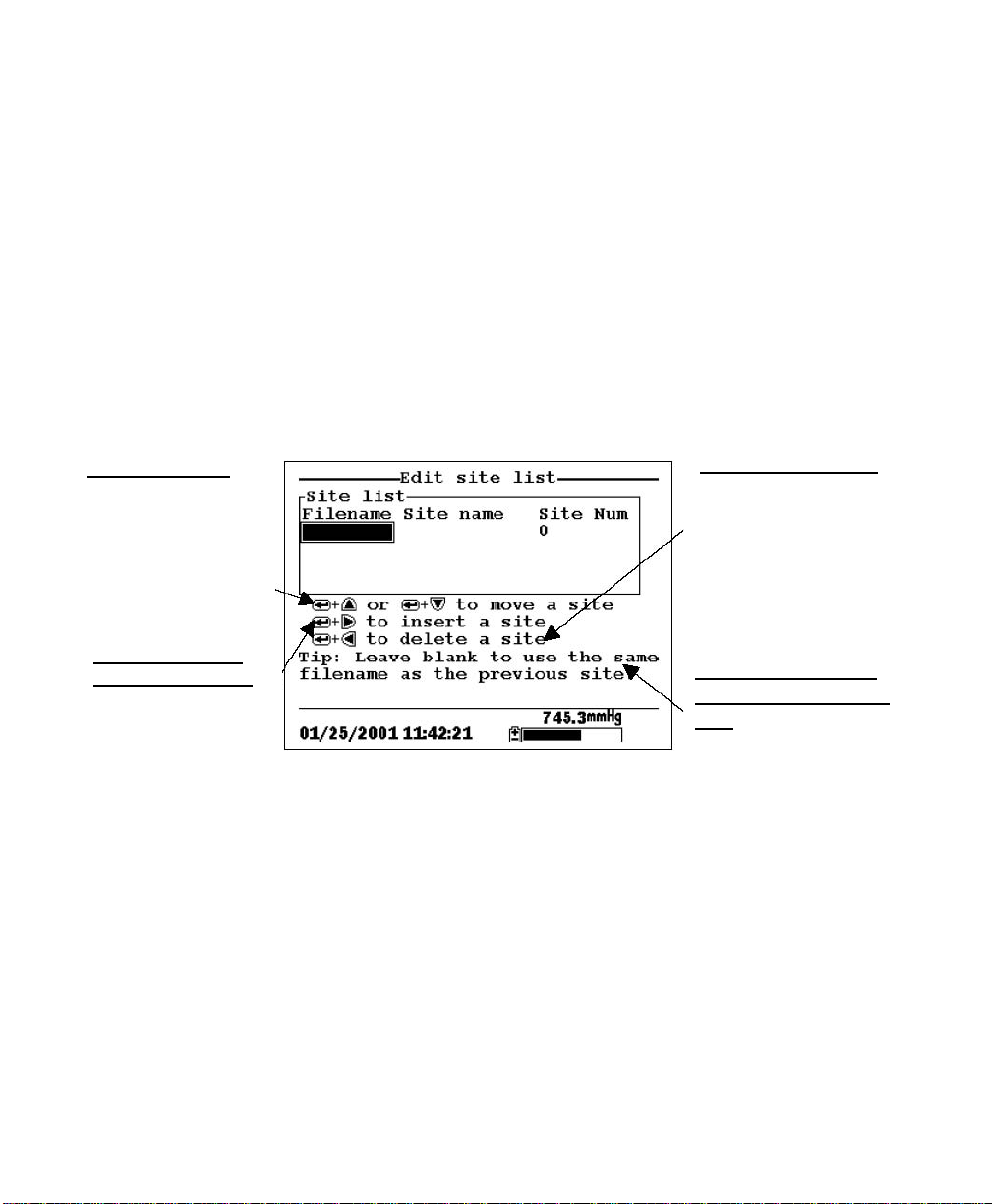
Section 9 Logging
9.5 Editing a Site List
1. Go to the logging setup screen as described in Section 9.1
Accessing the Logging Setup Screen.
2. Use the arrow keys to highlight the Edit Site List selection.
See Figure 9.6 Logging Setup Screen.
3. Press the Enter key. The edit site list screen is displayed.
4. Edit the site list using the keystrokes described below.
NOTE: Editing the site list will not have any effect on files
stored in the instrument memory.
To MOVE a site:
Use the arrow keys to
highlight a site. Press
the Up or Down
arrow key while
holding down the
Enter key.
To DELETE a site:
Use the arrow keys to
highlight a site. Press
the Left arrow key
while holding down
the Enter key.
To INSERT a site
above another site:
Use the arrow keys to
highlight the site.
Press the Right arrow
key while holding
down the Enter key.
Use keypad to input
letters. Refer to
Section 2.9 Keypad
Use.
Figure 9.1 Keystrokes for Editing Site List
To use the same file
name as the previous
site: Leave the
filename blank
9.6 Logging Data Without a Site List
1. Follow Steps 1 through 5 in Section 7.1 Real-Time Data.
2. Use the arrow keys to highlight the Log one sample selection
on the run screen if only a single sample is being logged.
YSI 556 MPS YSI Incorporated
Page 72
Page 79

Logging Section 9
OR Use the arrow keys to highlight the Start logging
selection on the run screen if a data stream is being logged.
Figure 9.9 Run Screen
3. Press the Enter key. The Enter information screen is
displayed.
Figure 9.10 Enter Information Screen
NOTE: The last filename used will be displayed.
4. Use the keypad to enter a file name. Refer to Section 2.9
Keypad Use.
NOTE: The instrument will assign a default file name of
NONAME if no file name is specified.
5. Press the Enter key to input the file name.
YSI Incorporated YSI 556 MPS
Page 73
Page 80

Section 9 Logging
6. Use the arrow keys to highlight the Site description field in
the enter information screen.
NOTE: Entering a Site Description is optional. You may
leave the Site Description blank and skip to Step 9.
7. Use the keypad to enter a site description name. Refer to
Section 2.9 Keypad Use.
8. Press the Enter key to input the site description.
NOTE: If you want to change the logging setup, such as
sampling interval or storing the barometer reading, use the
arrow keys to highlight the Configure field, press the Enter
key, then refer to Section 9.2 Setting Logging Interval or 9.3
Storing Barometer Readings for details.
9. Use the arrow keys to highlight the OK field in the center of
the information screen.
10. Press the Enter key to start logging.
NOTE: If the parameter mismatch screen is displayed, refer
to Section 9.8 Adding Data to Existing Files.
11. If a single point is being logged, the header on the run screen
changes momentarily from Menu to Sample logged to
confirm that the point was successfully logged. Skip to Step
Figure 9.11 Sample Logged Screen
YSI 556 MPS YSI Incorporated
Page 74
Page 81
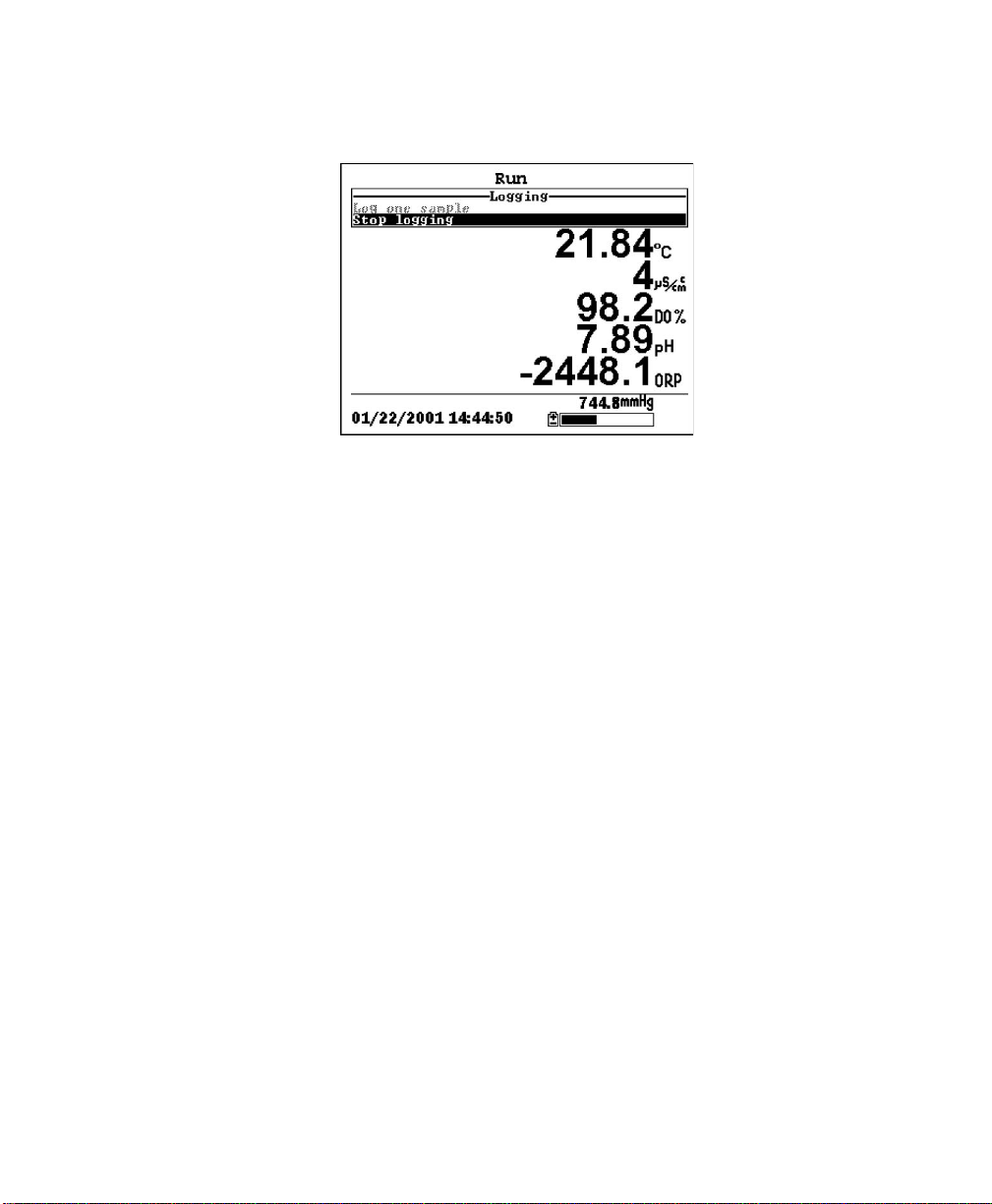
Logging Section 9
If a continuous stream of points is being logged, the start logging entry in
the run screen changes from Start logging to Stop logging.
Figure 9.12 Logging Screen
12. At the end of the logging interval, press Enter to stop
logging.
13. Refer to Section 8.3 View File to view the data on the
instrument display.
9.7 Logging Data with a Site List
1. If you have not already created a site list, refer to Section 9.4
Creating a Site List.
2. Follow Steps 1 through 5 in Section 7.1 Real-Time Data.
3. Use the arrow keys to highlight the Log one sample selection
on the run screen if only a single sample is being logged.
OR Use the arrow keys to highlight the Start logging
selection on the run screen if a data stream is being logged.
See Figure 9.9 Run Screen.
4. Press the Enter key. The Pick a site screen is displayed.
YSI Incorporated YSI 556 MPS
Page 75
Page 82

Section 9 Logging
Figure 9.13 Pick a Site Screen
5. Use the arrow keys to highlight the site of your choice.
NOTE: If the site of your choice is grayed out in the site list,
refer to Section 9.8 Adding Data to Existing Files.
NOTE: Refer to Section 9.5 Editing a Site List if you want to
edit the site list.
6. Press the Enter key to start logging.
NOTE: If the parameter mismatch screen is displayed, refer to
Section 9.8 Adding Data to Existing Files.
7. If a single point is being logged, the header on the run screen
changes momentarily from Menu to Sample logged to
confirm that the point was successfully logged. See Figure
9.11 Sample Logged Screen. Skip to Step 9.
If a continuous stream of points is being logged, the start
logging entry in the run screen changes from Start logging to
Stop logging. See Figure 9.12 Logging Screen.
8. At the end of the logging interval, press Enter to stop
logging.
YSI 556 MPS YSI Incorporated
Page 76
Page 83

Logging Section 9
9. Refer to Section 8.3 View File to view the data on the
instrument display.
9.8 Adding Data to Existing Files
In order to add new data to an existing file, the current logging and sensor
setup must be exactly the same as when the file was created. The following
settings must be the same:
• Sensors enabled (refer to Section 4 Sensors)
• Store Barometer (refer to Section 9.3 Storing Barometer
Readings)
• Store Site Number (refer to Section 9.4 Creating a Site
List)
If the current logging setup is not exactly the same as when the file was
created, a parameter mismatch screen is displayed.
Figure 9.14 Parameter Mismatch Screen
NOTE: The right column shows parameters used when the
file was created. The left column shows current parameters.
1. Press the Down Arrow key to scroll down and find the
mismatch(es).
2. Use the following chart to resolve the mismatch(es).
YSI Incorporated YSI 556 MPS
Page 77
Page 84

Section 9 Logging
Mismatch Action Reference
Sensor(s) missing Enable the missing Section 4 Sensors
from left column sensor(s)
Extra sensor(s) listed Disable the extra Section 4 Sensors
in left column sensor(s)
Barometer missing Enable the Store Section 9.3 Storing
from left column, Barometer setting Barometer Readings
but present in right
column
Barometer present in Disable the Store Section 9.3 Storing
left column, but Barometer setting Barometer Readings
missing from right
column
Store Site Number
missing from left Number setting Site List
column, but present
in right column
Store Site Number
present in left Number setting Site List
column, but missing
from right column
Enable the Store
Site
Disable the Store
Site
Section 9.4 Creating a
Section 9.4 Creating a
3. Return to Section 9.6 Logging Data without a Site List or 9.7
Logging Data with a Site List.
YSI 556 MPS YSI Incorporated
Page 78
Page 85

10. System Setup
The YSI 556 MPS has a number of features that are user-selectable or can
be configured to meet the user’s preferences. Most of these choices are
found in the System setup menu.
10.1 Accessing the System Setup Screen
1. Press the On/off key to display the run screen. See Figure
Front View of YSI 556 MPS.
2. Press the Escape key to display the main menu screen.
3. Use the arrow keys to highlight the System setup selection.
Figure 10.1 Main Menu
4. Press the Enter key. The system setup screen is displayed.
YSI Incorporated YSI 556 MPS
Page 79
Page 86

Section 10 System Setup
Figure 10.2 System Setup Screen
NOTE: The first line of the System setup menu shows the
current software version of your YSI 556 MPS. As software
enhancements are introduced, you will be able to upgrade
your YSI 556 MPS from the YSI Web site. Refer to Section
11.2 Upgrading YSI 556 MPS Software for details.
10.2 Language Setting
1. Go to the System Setup screen as described in Section 10.1
Accessing the System Setup Screen.
2. Use the arrow keys to highlight Language on the System
Setup screen. Press Enter to open the Language screen. .
3. Use the arrow keys to highlight your desired Language. Press
Enter.
4. Press the Escape key repeatedly to return to the Main men
10.3 Date and Time Setup
1. Go to the system setup screen as described in Section 10.1
Accessing the System Setup Screen.
YSI 556 MPS YSI Incorporated
Page 80
Page 87

System Setup Section 10
2. Use the arrow keys to highlight the Date & time selection on
the system setup screen. See Figure 10.2 System Setup
Screen.
3. Press Enter. The date and time setup screen is displayed.
Currently selected
date format
4-digit year
selected
Figure 10.3 Date Setup Screen
NOTE: A black dot to the left of a date format indicates that
format is selected.
4. Use the arrow keys to highlight your desired date format.
5. Press Enter.
6. Use the arrow keys to highlight the 4-digit year selection.
7. Press Enter. A check mark appears in the check box next to
the 4-digit year selection.
NOTE: If unchecked, a 2-digit year is used.
8. Use the arrow keys to highlight the Date selection.
9. Press Enter. A cursor appears over the first number in the
date.
YSI Incorporated YSI 556 MPS
Page 81
Page 88

Section 10 System Setup
10. Enter the proper number from the keypad for the highlighted
date digit. The cursor moves automatically to the next date
digit. Refer to Section 2.9 Keypad Use for more keypad
information.
11. Repeat Step 10 until all date digits are correct.
12. Press Enter to input the specified date.
13. Use the arrow keys to highlight the Time selection.
14. Press Enter. A cursor appears over the first number in the
time selection.
15. Enter the proper number from the keypad for the highlighted
time digit. The cursor moves automatically to the next time
digit.
NOTE: Use military format when entering time. For
example, 2:00 PM is entered as 14:00.
16. Repeat Step 15 until all time digits are correct.
17. Press Enter to input the correct time.
18. Press the Escape key repeatedly to return to the Main menu
screen.
10.4 Data Filter
The Data Filter is a software filter that eliminates sensor noise and provides
more stable readings.
NOTE: YSI recommends using the default values for the data filter for
most field applications.
However, users who are primarily interested in a fast response from their
dissolved oxygen sensor should consider a change of the default time
constant setting of 8 seconds to one of 2 seconds. This change can be made
according to the instructions in Section 10.3.1 Changing the Data Filter
Settings below. The disadvantage of lowering the time constant is that field
pH readings may appear somewhat noisy if the cable is in motion.
YSI 556 MPS YSI Incorporated
Page 82
Page 89

System Setup Section 10
10.4.1 Changing the Data Filter Settings
1. Go to the system setup screen as described in Section 10.1
Accessing the System Setup Screen.
2. Use the arrow keys to highlight the Data filter selection. See
Figure 10.1 Main Menu.
3. Press the Enter key. The Data filter setup screen is displayed.
Figure 10.4 Data Filter Screen
4. With Enabled highlighted, press the Enter key to Enable or
Disable the data filter. A black dot to the left of the selection
indicates the data filter is enabled.
5. Use the arrow keys to highlight the Time constant field.
NOTE: This value is the time constant in seconds for the
software data filter. Increasing the time constant will result in
greater filtering of the data, but will also slow down the
apparent response of the sensors.
6. Use the keypad to enter a value. The default value is 8 and
this value is ideal for most 556 field applications. As
described in Section 10.3 Data Filter above, users who wish
to decrease the response time of the DO readings at the
expense of some noise for the pH readings determined
YSI Incorporated YSI 556 MPS
Page 83
Page 90

Section 10 System Setup
concurrently, should change the Time Constant to a value of
2.
7. Press the Enter key to enter the time constant.
8. Use the arrow keys to highlight the Threshold field.
NOTE: This value determines when the software data filter
will engage/disengage, speeding the response to large changes
in a reading. When the difference between two consecutive
readings is larger than the threshold, then the reading is
displayed unfiltered. When the difference between two
consecutive readings drops below the threshold, readings will
be filtered again.
9. Use the keypad to enter a value. The default value is 0.01.
10. Press the Enter key to enter the threshold.
11. Press the Escape key repeatedly to return to the Main menu
screen.
10.5 Shutoff Time
The YSI 556 MPS shuts off automatically after 30 minutes of inactivity. The
shut off time may be changed as described below.
1. Go to the system setup screen as described in Section 10.1
Accessing the System Setup Screen.
2. Use the arrow keys to highlight the Shutoff time selection on
the system setup screen. See Figure 10.2 System Setup
Screen.
3. Use the keypad to enter a value from 0 to 60 minutes. The
default value is 30.
NOTE: To disable the automatic shutoff feature, enter a zero
(0).
4. Press the Enter key to enter the correct shutoff time.
YSI 556 MPS YSI Incorporated
Page 84
Page 91

System Setup Section 10
5. Press the Escape key repeatedly to return to the main menu
screen.
10.6 Comma Radix
The user can toggle between a period (default) and comma for the radix
mark by selecting this item and pressing the Enter key as follows:
1. Go to the system setup screen as described in Section 10.1
Accessing the System Setup Screen.
2. Use the arrow keys to highlight the Comma radix selection
on the system setup screen. See Figure 10.2 System Setup
Screen.
3. Press the Enter key. A check mark appears in the check box
next to the comma radix selection indicating that the radix
mark is a comma.
10.7 ID
This selection allows you to enter an identification name/number for your
YSI 556 MPS. This ID name/number is logged in the header of each file.
1. Go to the system setup screen as described in Section 10.1
Accessing the System Setup Screen.
2. Use the arrow keys to highlight the ID selection. See Figure
10.1 Main Menu.
3. Use the keypad to enter an alphanumeric ID up to 15
characters in length. Refer to Section 2.9 Keypad Use.
4. Press the Enter key to enter the ID.
5. Press the Escape key repeatedly to return to the main menu
screen.
10.8 GLP Filename
This selection allows you to enter a different filename for the YSI 556 MPS
Calibration Record file.
YSI Incorporated YSI 556 MPS
Page 85
Page 92

Section 10 System Setup
NOTE: The default filename is the “556 PC board Serial Number.glp.”
1. Go to the system setup screen as described in Section 10.1
Accessing the System Setup Screen.
2. Use the arrow keys to highlight the GLP Filename selection.
See Figure 10.1 Main Menu.
3. Use the keypad to enter a filename up to 8 characters in
length. Refer to Section 2.9 Keypad Use.
4. Press the Enter key to enter the new filename.
5. Press the Escape key repeatedly to return to the main menu
screen.
10.9 TDS Constant
This selection allows you to set the constant used to calculate
Total Dissolved Solids (TDS). TDS in g/L is calculated by
multiplying this constant times the specific conductance in
mS/cm.
10.9.1 Changing the TDS Constant
1. Go to the system setup screen as described in Section 10.1
Accessing the System Setup Screen.
2. Use the arrow keys to highlight the TDS Constant selection.
See Figure 10.1 Main Menu.
3. Use the keypad to enter a value. Refer to Section 2.9 Keypad
Use. The default value is 0.65.
4. Press the Enter key to enter the correct TDS constant.
5. Press the Escape key repeatedly to return to the main menu
screen.
YSI 556 MPS YSI Incorporated
Page 86
Page 93

System Setup Section 10
10.10 Barometer Units
The following information is only for instruments with the barometer
option.
1. Go to the system setup screen as described in Section 10.1
Accessing the System Setup Screen.
2. Use the arrow keys to highlight the Barometer units
selection on the system setup screen. See Figure 10.2 System
Setup Screen.
3. Press the Enter key. The Barometer units screen will appear.
Figure 10.5 Data Filter Screen
A black dot indicates the currently selected units.
4. Use the arrow keys to highlight your desired barometric unit.
5. Press the Enter key to select your choice. A black dot will
appear in the circle next to your selected units.
6. Press the Escape key repeatedly to return to the main menu
screen.
YSI Incorporated YSI 556 MPS
Page 87
Page 94
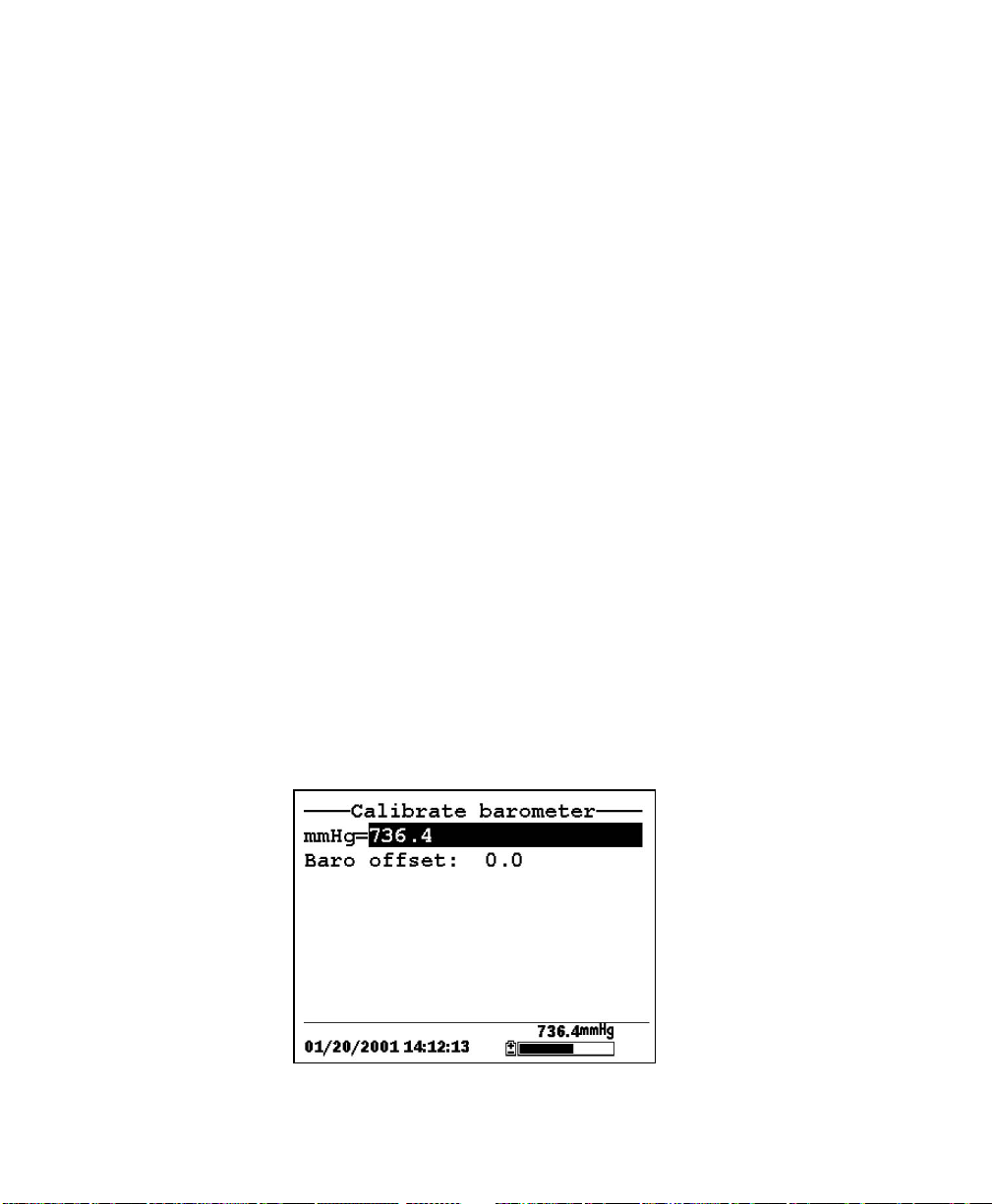
Section 10 System Setup
10.11 Calibrate Barometer
The optional barometer has been factory calibrated to provide accurate
readings. However, some sensor drift may occur over time, requiring
occasional calibration by the user, as follows:
1. Determine your local barometric pressure from an
independent laboratory barometer or from your local weather
service.
2. If the barometric pressure (BP) reading is from your local
weather station, reverse the equation that corrects it to sea
level.
NOTE: For this equation to be accurate, the barometric
pressure units must be in mmHg.
True BP = (Corrected BP) – [2.5 * (Local Altitude/100)]
3. Go to the system setup screen as described in Section 10.1
Accessing the System Setup Screen.
4. Use the arrow keys to highlight the Calibrate barometer
selection on the system setup screen. See Figure 10.2 System
Setup Screen.
5. Press the Enter key. The Calibrate Barometer screen is
displayed.
Figure 10.6 Barometer Calibration Screen
YSI 556 MPS YSI Incorporated
Page 88
Page 95

System Setup Section 10
6. Use the keypad to input the known barometric pressure value
as determined in Step 2.
7. Press the Enter key. The new barometer reading is displayed
as well as the approximate offset from the factory reading.
NOTE: To return the sensor to the factory setting, subtract
the offset amount from the current setting and repeat Steps 5
to 7.
8. Press the Escape key repeatedly to return to the main menu
screen.
YSI Incorporated YSI 556 MPS
Page 89
Page 96

11. Maintenance
11.1 Sensor Care and Maintenance
Once the sensors have been properly installed, remember that periodic
cleaning and DO membrane changes are required.
11.1.1 DO Sensor
For best results, we recommend that the KCl solution and the membrane cap
be changed at least once every 30 days.
1. It is important to recognize that oxygen dissolved in the
sample is consumed during sensor operation. It is therefore
essential that the sample be continuously stirred at the sensor
tip. If stagnation occurs, your readings will be artificially low.
Stirring may be accomplished by mechanically moving the
sample around the sensor tip, or by rapidly moving the sensor
through the sample. The rate of stirring should be at least 1
foot per second.
2. Membrane life depends on usage. Membranes will last a long
time if installed properly and treated with care. Erratic
readings are a result of loose, wrinkled, damaged, or fouled
membranes, or from large (more than 1/8" diameter) bubbles
in the electrolyte reservoir. If erratic readings or evidence of
membrane damage occurs, you should replace the membrane
and the electrolyte solution. The average replacement interval
is two to four weeks.
3. If the membrane is coated with oxygen consuming (e.g.
bacteria) or oxygen producing organisms (e.g. algae),
erroneous readings may occur.
4. Chlorine, sulfur dioxide, nitric oxide, and nitrous oxide can
affect readings by behaving like oxygen at the sensor. If you
suspect erroneous readings, it may be necessary to determine
if these gases are the cause.
5. Avoid any environment that contains substances that may
attack the probe module and sensor materials. Some of these
substances are concentrated acids, caustics, and strong
solvents. The sensor materials that come in contact
YSI Incorporated YSI 556 MPS
Page 90
Page 97

Maintenance Section 11
with the sample include FEP Teflon, acrylic plastic, EPR
rubber, stainless steel, epoxy, polyetherimide and the PVC
cable covering.
6. It is possible for the silver anode, which is the entire silver
body of the sensor, to become contaminated. This will prevent
successful calibration. To restore the anode, refer to Section
11.1.1 DO Sensor, Silver Anode Cleaning.
7. For correct sensor operation, the gold cathode must always be
bright. If it is tarnished (which can result from contact with
certain gases), or plated with silver (which can result from
extended use with a loose or wrinkled membrane), the gold
surface must be restored. To restore the cathode, refer to
Section 11.1.1 DO Sensor, Gold Cathode Cleaning.
8. To keep the electrolyte from drying out, store the sensor in the
transport/calibration cup with at least 1/8″ of water.
Silver Anode Cleaning
After extended use, a thick layer of AgCl builds up on the silver anode
reducing the sensitivity of the sensor. The anode must be cleaned to remove
this layer and restore proper performance. The cleaning can be chemical or
mechanical:
Chemical Cleaning: Remove the membrane cap and soak the entire anode
section in a 14% ammonium hydroxide solution for 2 to 3 minutes, followed
by a thorough rinsing with distilled or deionized water. The anode should
then be thoroughly wiped with a wet paper towel to remove the residual
layer from the anode.
Mechanical Cleaning: Sand off the dark layer from the silver anode with
400 grit wet/dry sandpaper. Wrap the sandpaper around the anode and twist
the sensor. Rinse the anode with clean water after sanding, followed by
wiping thoroughly with a wet paper towel.
NOTE: After cleaning, a new membrane cap must be installed. Refer to
Section 3.4.3 Membrane Cap Installation.
Turn the instrument on and allow the system to stabilize for at least 30
minutes. If, after several hours, you are still unable to calibrate, contact your
dealer or YSI Customer Service. Refer to Appendix E Customer Service.
YSI Incorporated YSI 556 MPS
Page 91
Page 98

Section 11 Maintenance
Gold Cathode Cleaning
For correct sensor operation, the gold cathode must be textured properly. It
can become tarnished or plated with silver after extended use. The gold
cathode can be cleaned by using the adhesive backed sanding disc and tool
provided in the YSI 5238 Probe Reconditioning Kit.
Using the sanding paper provided in the YSI 5238 Probe Reconditioning
Kit, wet sand the gold with a twisting motion about 3 times or until all silver
deposits are removed and the gold appears to have a matte finish. Rinse the
cathode with clean water after sanding, followed by wiping thoroughly with
a wet paper towel. If the cathode remains tarnished, contact your dealer or
YSI Customer Service. Refer to Appendix E Customer Service.
NOTE: After cleaning, a new membrane cap must be installed. Refer to
Section 3.4.3 Membrane Cap Installation.
11.1.2 DO Sensor Replacement
1. Remove the probe sensor guard.
CAUTION: Thoroughly dry the sensor so that no water enters the probe
module sensor port when the sensor is removed.
2. Insert the long end of the hex key wrench into the small hole
in the side of the probe module bulkhead. Turn the wrench
counterclockwise and remove the screw. (You do not have to
remove the screw all the way to release the sensor.)
3. Pull the old DO sensor module straight out of the probe
module body.
NOTE: The DO sensor is not threaded, it is keyed, so it
cannot be removed by twisting.
YSI 556 MPS YSI Incorporated
Page 92
Page 99

Maintenance Section 11
Probe Sensor
Guard
Set Screw
DO Sensor
Hex Key
Wrench
F
igure 11.1 DO Sensor Replacement
4. Insert the new DO sensor module. Make sure that the inside
of the probe module sensor port and the o-ring on the sensor
are clean, with no contaminants, such as grease, dirt, or hair.
The DO sensor is keyed, or has a flat side, so that it cannot be
aligned improperly.
NOTE: Make sure the DO sensor bottoms out before the set
screw is inserted.
5. Insert the set screw into the small hole in the side of the probe
module bulkhead, and turn clockwise to rethread.
CAUTION: Make sure that you do not cross-thread the set
screw. Use the hex key wrench to tighten the screw in properly,
making sure that the screw does not stick out of the side of the
probe module bulkhead. The probe sensor guard will not thread
on properly and damage may result if the screw is allowed to
stick out.
YSI Incorporated YSI 556 MPS
Page 93
Page 100

Section 11 Maintenance
NOTE: The YSI 5563 DO sensor is shipped dry. A shipping
membrane was installed to protect the electrode. A new
membrane cap must be installed before the first use. Refer to
Section 3.4.1 Sensor Installation.
11.1.3 YSI 5564 pH and 5565 Combination pH/ORP Sensor Cleaning
Cleaning is required whenever deposits or contaminants appear on
the glass and/or platinum surfaces of these sensors or when the
response of the sensor becomes slow.
1. Remove the sensor from the probe module.
2. Initially, simply use clean water and a soft clean cloth, lens
cleaning tissue, or cotton swab to remove all foreign material
from the glass bulb (YSI 5564 and YSI 5565) and platinum
button (YSI 5565). Then use a moistened cotton swab to
carefully remove any material that may be blocking the
reference electrode junction of the sensor.
CAUTION: When using a cotton swab with the YSI 5564 or
YSI 5565, be careful NOT to wedge the swab tip between the
guard and the glass sensor. If necessary, remove cotton from the
swab tip, so that the cotton can reach all parts of the sensor tip
without stress.
NOTE: If good pH and/or ORP response is not restored by the
above procedure, perform the following additional procedure:
1. Soak the sensor for 10-15 minutes in clean water containing a
few drops of commercial dishwashing liquid.
2. GENTLY clean the glass bulb and platinum button by rubbing
with a cotton swab soaked in the cleaning solution.
3. Rinse the sensor in clean water, wipe with a cotton swab
saturated with clean water, and then re-rinse with clean water.
NOTE: If good pH and/or ORP response is still not restored
by the above procedure, perform the following additional
procedure:
YSI 556 MPS YSI Incorporated
Page 94
 Loading...