

Page 1
YSI 5300A
Biologic al O xyg en
Monitor System
Operations
Manual
Page 2

Page 3

Table of Contents
1. Introduction.............................................................................................................. 1
2. Installing and Initial Setup ...................................................................................... 2
2.1 Unpacking the System........................................................................................................2
2.2 Completing the Warranty Card...........................................................................................2
2.3 Viewing the Front and Back Panels ...................................................................................3
2.4 Setting Up the Software......................................................................................................5
2.5 Setting Up the Standard System.........................................................................................7
2.6 Setting Up the Micro System..............................................................................................9
3. Preparing your Bath Assembly............................................................................. 11
3.1 Choosing your Bath Assembly.........................................................................................11
3.2 Setting up your Bath Assembly........................................................................................13
4. Preparing your Oxygen Probe..............................................................................15
4.1 Standard Oxygen Probe....................................................................................................15
4.2 Micro Oxygen Probe ........................................................................................................17
5. Operating your Oxygen Probe.............................................................................. 18
5.1 Principles of Operation.....................................................................................................18
5.2 Electrical Characteristics..................................................................................................18
5.3 Voltage Plateau.................................................................................................................18
5.4 Noise.................................................................................................................................19
5.5 Temperature......................................................................................................................19
5.6 Oxygen Consumption by the Probe..................................................................................19
5.7 Electrolyte Saturation and Bubbles in Electrolyte............................................................20
5.8 Drift of Calibration...........................................................................................................20
5.9 Probe Care and Maintenance............................................................................................20
6. Operating your Oxygen System ........................................................................... 22
6.1 Calibrating........................................................................................................................22
6.2 Daily Probe Test...............................................................................................................24
6.3 Sample Monitoring...........................................................................................................24
7. Troubleshooting.....................................................................................................26
8. Warranty and Repair..............................................................................................28
8.1 Cleaning Instructions........................................................................................................29
8.2 Packing Instructions .........................................................................................................30
9. Required Notice ..................................................................................................... 31
10. Accessories and Replacement Parts................................................................ 32
i
Page 4

11. Appendix A - Specifications..............................................................................33
12. Appendix B – Tables.......................................................................................... 35
13. Appendix C - Required Notice........................................................................... 40
14. Appendix D: Application Notes........................................................................ 41
15. Appendix E: Gas Solubility Relationships...................................................... 42
16. Appendix F: Interfering Gases......................................................................... 43
ii
Page 5

1. Introduction
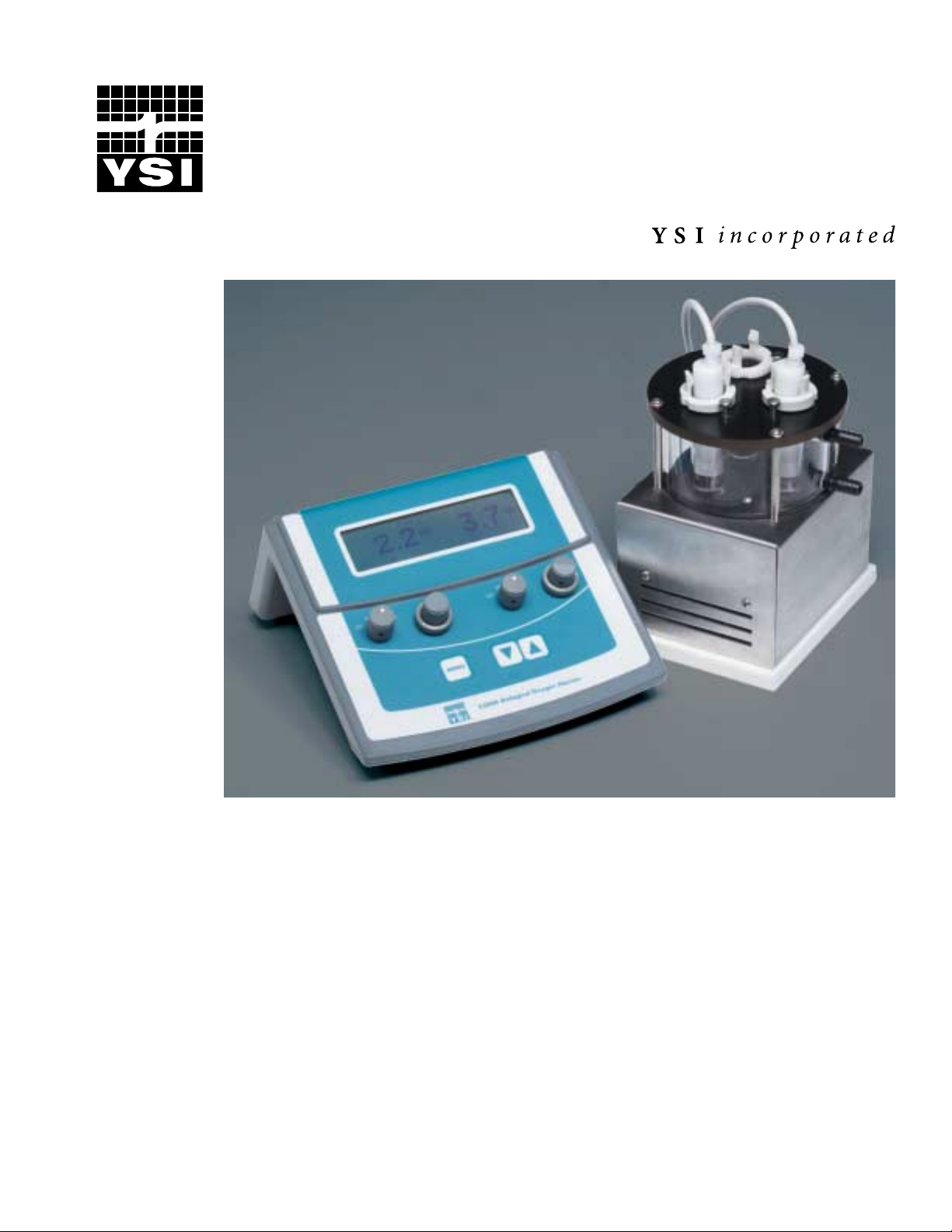
The YSI 5300A Biological Oxygen Monitor is designed to measure oxygen uptake and evolution
in biological systems. It utilizes Clark type polarographic oxygen probes immersed in
magnetically stirred sample chambers, and produces oxygen uptake or evolution curves in 2 to
15 minutes. This two-channel instrument offers simultaneous display, recorder outputs, and RS232 serial outputs for monitoring the results of each evaluation of samples.
Two different sensor systems are available. The "Standard System", for the measurement of
samples of 3 to 8 ml, consists of a 5300A Monitor, a 5301B Standard Bath, two 5331A Oxygen
Probes, and other supplies. The 5304 Micro Adapter Kit will modify the 5301B for use with 1 ml
samples. The "Micro System," for the measurement of a fixed volume sample of 600 µL or for a
continuous flowing sample, includes a 5300A Monitor, one or two 5356 Micro Oxygen
Chambers, one or two 5357 Micro Oxygen Probes, and other supplies. The Micro Oxygen
Chamber and the Micro Probe are manufactured by Instech Laboratories, Inc..
The YSI 5331A and YSI 5357 Oxygen Probes are a complete polarographic system consisting of
a platinum cathode, silver anode and KCl solution held captive around electrodes by a Teflon
membrane fastened with an o-ring. When a polarizing voltage is applied across the probe, all
oxygen in the probe is consumed (reduced) at the cathode and current flows in direct
stoichiometric relation to the rate of oxygen consumption (reduction). Oxygen then diffuses
through the membrane at a rate proportional to the oxygen pressure outside the probe, since
oxygen pressure in the probe is near zero. When steady state conditions are reached in about 30
seconds, current flows through the probe at a rate in proportion to the external oxygen pressure.
The YSI 5301B Bath Assembly has three sample chambers with built-in magnetic stirrers
surrounded by a water bath. The YSI 5301B is able to measure sample size from 3 to 8 mL with
the YSI 5331A probes. The YSI 5304 Micro Adapter Kit modifies the YSI 5301B for use with
1-mL samples and requires the YSI 5331 probes as well. The YSI 5301B Bath Assembly is
connected with a constant temperature circulator (YSI 5310) and together they provide a
temperature controlled environment where the oxygen uptake and evolution can be accurately
monitored in a sample. The Lucite plunger included with the YSI5301 Bath Assembly provides
an access slot for the introduction of samples, inhibitors and activators into the sample chamber.
1
Page 6

2. Installing and Initial Setup
Except when operating at ambient temperatures, a constant temperature circulator is necessary to
control the temperature of the sample chambers (YSI recommends a constant temperature
circulator with a +/- 0.02 °C control for maximum accuracy). A 2 channel chart recorder, serial
printer, or computer (equipped with an RS232 port or data acquisition system) is necessary for a
hard copy of experimental results. Your YSI dealer can recommend and offer suitable circulators
(YSI 5310) and chart recorders (YSI 5320).
2.1 Unpacking the System
When you unpack your new YSI 5300A Biological Oxygen Monitor for the first time, check the
packing list to make sure you have received everything you should have. If there is anything
missing or damaged, call the dealer from whom you purchased the system. If you do not know
which of our authorized dealers sold the system to you, call YSI Customer Service at 800-6598895 or 937-767-7241, or email us at lifesciences@ysi.com and we'll be happy to help you.
2.2 Completing the Warranty Card
Please complete the Warranty Card and return it to YSI. This will record your purchase of this
instrument in our computer system. Once your purchase is recorded, you will receive prompt,
efficient service in the event any part of your YSI 5300A should ever need repair.
2
Page 7

2.3 Viewing the Front and Back Panels
2.3.1 Front Panel
The front panel of the YSI 5300A contains the display screen, TEST/AIR/ O2/ TEST setting
dials, calibration adjustment dial, Menu, and toggling keys as shown below.
Channel 1 Setting Dial
TEST/AIR/O2/TEST
Channel 1
Calibration Dial
Display Screen
Menu Selection Key
Toggling
Up/Down Keys
Channel 2 Setting Dial
TEST/AIR/O2/TEST
3
Channel 2
Calibration Dial
Page 8
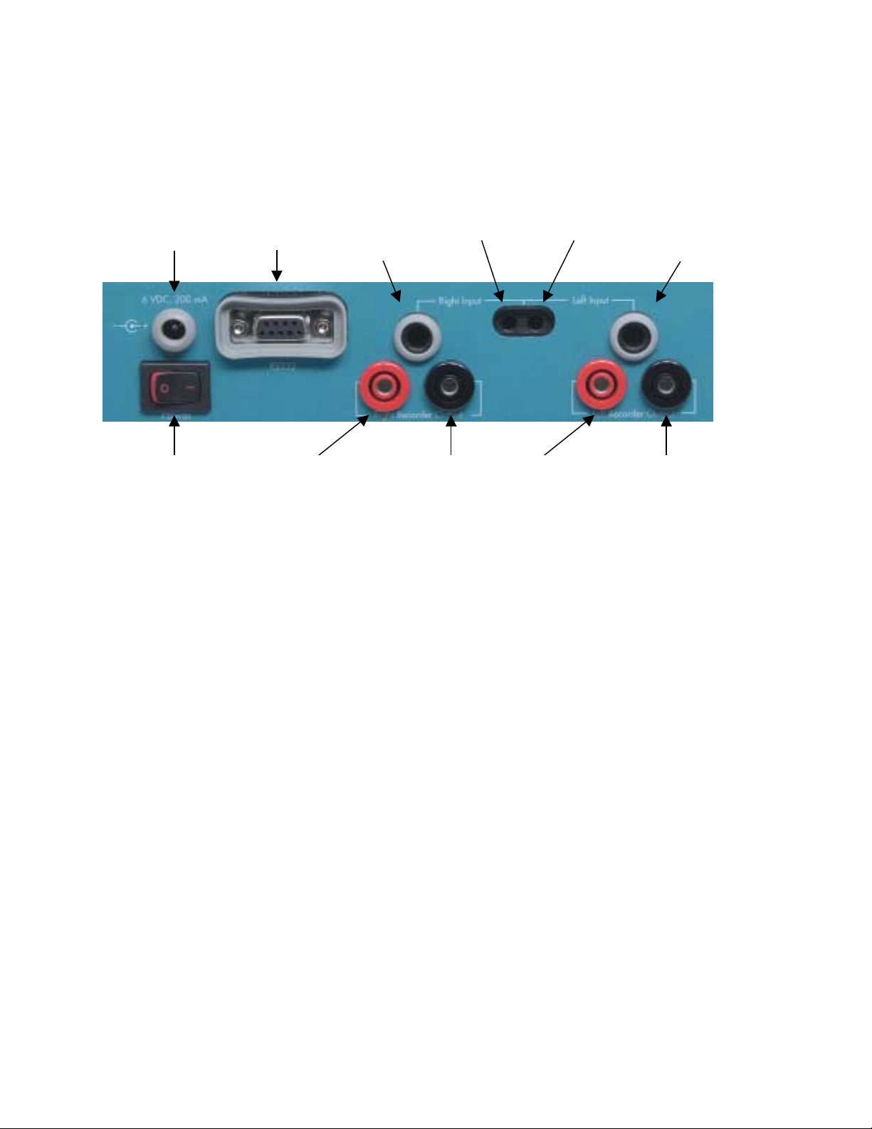
2.3.2 Rear Panel
The rear panel contains the connections for the power supply, power supply switch, YSI 5331A
probes, YSI 5357 Micro Oxygen Probes, RS232 serial port, and recorder outputs.
Power
Supply
Connection
RS-232
Serial Port
Connection
Right Channel
YSI 5331A
Oxygen
Probe Input
Right Channel
YSI 5357 Micro
Probe Input
Left Channel
YSI 5357 Micro
Probe Input
Left Channel
YSI 5331A
Oxygen
Probe Input
Power Supply
Switch
Right Channel
Positive (+)
Recorder Output
Right Channel
Negative (-) Ground
Recorder Output
Left Channel
Positive (+)
Recorder Output
Left Channel
Negative (-) Ground
Recorder Output
Power Supply Connection
The power supply connection requires a 6 VDC power supply with a least 200mA current.
Oxygen Probe Connections
The YSI 5331A has a 0.25” Stereo Phone Plug. The YSI 5357/ 5358 Micro Probe System has a
0.173" miniature telephone plug.
Note: The YSI 5331 Oxygen Probes are not compatible with the YSI 5300A Monitoring
System. Only the YSI 5331A oxygen probe and the YSI 5357/ 5358 micro oxygen probe
system are compatible with the YSI 5300A Monitor.
RS232 Connection
The RS232 connection is a standard DB9 connector. Use a straight serial cable (not a null
modem) to connect the YSI 5300A to a computer serial port or a serial printer. See Accessories
and Replacement Parts, Sec. 11 for the YSI item number.
4
Page 9

2.4 Setting Up the Software
The YSI 5300 has two primary modes: monitoring/calibration mode and the zero calibration/
RS-232 setup mode.
1. The monitoring/ calibration mode is the default mode and is shown below. In this mode the
analyzer is constantly measuring oxygen. The analyzer can also be calibrated in this mode
by unlocking the calibration dial and setting the analyzer to the appropriate calibration value.
(See Sec. 6 for calibration instructions.)
%AIR
%AIR
89.0
Press the up and
down ke ys to zero
adjust the reading
89.0
2. To adjust the contrast on the display screen, press the [▲] up soft-key or the [▼] down softkey in the sampling/ calibration mode.
3. To enter the zero calibration/ RS-232 setup mode press the [MENU] soft-key.
4. The Left Channel Zero Calibration screen will first be displayed. A zero percent sample will
be used to adjust at the zero point calibration at this menu. Adjust the zero point to reflect
0.0% with this zero percent oxygen sample. The left channel zero calibration will display
actual oxygen readings. (See Sec 6.1 for zero calibration instructions.)
Left Channel Zero Calibration
0.0
Press MENU to conti nue
5. Press the [MENU] soft-key again and following screen will be displayed.
%AIR
Right Channel Zero Calibration
Press the up and
down ke ys to zero
adjust the reading
Press MENU to conti nue
A zero percent sample will be used to adjust at the zero point calibration at this menu. Adjust the
zero point to reflect 0.0 % with this zero percent oxygen sample. The left channel zero
calibration will display actual oxygen readings. (See Sec 6.1 for zero calibration instructions.)
6. Press the [MENU] soft-key again and following screen will be displayed
0.0
5
%AIR
Page 10

RS232 Serial Output
OFF
Press UP or DOWN to select
--
> ON
Press MENU to continue
7. Select On or Off to activate or disable the RS232 Serial Output option for serial port data
acquisition and collection.
8. Press the [MENU] soft-key again and following screen will be displayed.
Serial Output Data Ra te
10 seco nds
Press UP or DOWN to select
Press MENU to continue
9. Select the serial output data rate via the RS-232 serial output for your data collection needs.
(Output data rate ranges from 1 to 60 seconds). Compare your computer or serial printer’s
requirements with YSI 5300A setting.
10. Press the [MENU] soft-key again and following screen will be displayed.
Serial O utput Baud Rate
2400
4800
Press UP or DOWN to select
--
> 9600
Press MENU to continue
11. Select the appropriate serial output baud rate for your data acquisition requirements.
Compare your computer or serial printer’s requirements with YSI 5300A setting.
12. Press the [MENU] soft-key again and following screen will be displayed.
Serial Output Parity
ODD
EVEN
Press UP or DOWN to select
--
> NONE
Press MENU to continue
13. Select the appropriate serial output parity per your data acquisition requirements. Compare
your computer or serial printer’s requirements with YSI 5300A setting.
14. Press the [MENU] soft-key again and following screen will be displayed.
6
Page 11

Serial O utput Line T erminator
CR
LF
LF/CR
Press UP or DOWN to select
--
> CR/LF
Press MENU to continue
15. Select the appropriate serial output line terminator per your data acquisition requirements.
Compare your computer or serial printer’s requirements with YSI 5300A setting.
16. Press the [MENU] soft-key again and following screen will be displayed.
Probe Bias Voltages
Normal Test
0.70 volts 0.80 volts
Press UP or DOWN to select
Press MENU to continue
17. The probe bias voltages screen shows the difference in the voltages between the normal
mode and the test mode for both probes.
18. Press the [MENU] soft-key again and following screen will be displayed.
Reset All Sys tem Parameters to Default
YES
Select YES and press menu to reset
Press NO and press menu to continue
--
> NO
The Reset All System Parameters to Default screen allows the user to reset the analyzer to the
factory default settings.
NOTE: Inactivity in the zero calibration/ RS-232 setup mode will cause the analyzer to
default to the calibration/ sampling mode after ~15 seconds.
2.5 Setting Up the Standard System
Description
The YSI 5300A Biological Oxygen Monitor standard system consists of the following separate
YSI products:
• 1 YSI 5300A Biological Oxygen Monitor
• 1 YSI 5301B Standard Bath Assembly (includes 1 5350 Membrane Mounting Kit, 1
5225 Sample Chamber kit, tubing, etc.)
7
Page 12

• 2 YSI 5331 Oxygen Probes, each with a 5775 Standard Membrane/KCl Kit
The assembled 5301B Standard Bath Assembly has three sample chambers with magnetic
stirrers, surrounded by a water chamber. A constant temperature circulator is connected to the
bath. Two 5331 Oxygen Probes are prepared for operation using the 5350 Membrane Mounting
Kit to install the parts found in the 5775 Standard Membrane/KCl Kit. The probes are held in
plungers that fit closely into the sample chambers. The probes plug into the back of the
instrument.
Assembling the Standard System:
1. Insert three glass sample chambers from the box marked 5215 (included with the 5301B)
into the holes in the bath cover.
2. Wet three of the large rubber o-rings with distilled or de-ionized water.
3. Place one rubber o-ring over each of the sample chambers near its top (the o-rings should
seat against the top cover).
4. Slide each sample chamber into the bath until it rests on its stop.
5. Place a white nylon hold down ring over each chamber (above the o-ring), push it down
and twist clockwise to secure it under the stainless steel shoulder screws (this will seat the
o-rings against the top cover for a water-tight seal).
Caution: Over-tightening the hold down ring may break the sample chamber.
6. Make sure that the power switches on the 5301B Bath Assembly and 5300A Monitor are
in the off (0) position, then plug the power cords into a properly grounded power
receptacle.
7. If the constant temperature circulator is used for your application, connect the 5301B Bath
Assembly to the circulator using the YSI 5315 Plumbing Kit. (Wetting the tubing ends
with water or alcohol will ease the tubing installation). Though it is not critical which
5301B tubing fitting is used as the inlet, YSI recommends using the bottom fitting.
8. Fill the circulator with distilled water and set the controls to the desired temperature.
Operate the circulator according to its instruction manual. Note: YSI recommends using
only distilled water in the bath. If distilled water is not used, minor rust stains may appear
in the 5301B Bath chamber. They may be removed using a mildly abrasive pad.
9. If the chart recorder is used for your application, connect a recorder to the recorder output
port on the back of the 5300A Monitor. The 5300A Monitor has a self-zeroing feature
with no probes plugged in; the recorder zero reference can be set with this zero output.
NOTE: The red port on the 5300A Monitor back panel is positive and the black port is
negative.
10. If the RS-232 serial cable is used for your application, connect the RS-232 serial cable to
both the YSI 5300A RS-232 port and the acquisition serial data port.
11. Prepare the 5331 Oxygen Probes for operation as described in section 4.1.
8
Page 13

12. Plug the 5331 Oxygen Probes into the jack marked Input on the rear of the 5300A
Monitor.
NOTE: When a 5331 Oxygen Probe and a Micro Oxygen Probe are both plugged into
the same channel’s input jacks, the display and output values reflect the YSI 5357
Micro Oxygen Probe response.
13. Numbered marking tape is supplied with the 5301B Bath Assembly to identify each probe
if desired.
2.6 Setting Up the Micro System
Description
The YSI 5300 Biological Oxygen Monitor Micro System consists of the following components:
• 1 YSI 5300A Biological Oxygen Monitor
• 1 or 2 YSI 5356 Micro Oxygen Chambers
• 1 or 2 YSI 5357 Micro Oxygen Probes
• 1 or 2 YSI 5358 Cable Assemblies
• 1 YSI 5775 Standard Membrane Kit
You can use the 5356 Micro Oxygen Chamber for fixed-volume single samples or for
continuous, flow-through monitoring. You should use a constant temperature circulator to
control the block temperature. A remote magnetic stirrer controller keeps the sample chamber
stirred when you measure fixed-volume samples.
Assembling the Micro System as follows:
1. Assemble the YSI 5356 Micro Oxygen Chamber as described in the Instech Laboratories
Model 600A Instruction Manual provided.
2. Connect the Oxygen Chamber to a constant temperature circulator (tubing not supplied).
3. Fill the circulator with distilled or de-ionized water and set it to the desired temperature.
Operate the circulator according to its instruction manual.
4. If the chart recorder is used for your application, connect a recorder to the recorder ports
on the rear of the monitor. NOTE: The red port on the 5300A Monitor back panel is
positive and the black port is negative.
5. If the RS-232 serial cable is used for your application, connect the RS-232 serial cable to
both the YSI 5300A RS-232 port and the acquisition serial data port.
6. Prepare the Micro Probe for operation as described in the Instech Laboratories Model
125/05 manual.
7. Thread the probe into the 5358 Cable Assembly.
8. With the monitor off, plug the Cable Assembly into the appropriate jack on the back of the
YSI 5300A.
9
Page 14

NOTE: When a Standard Oxygen Probe and a Micro Oxygen Probe are both plugged into the
same channel's input jacks, the display and recorder values reflect the Micro Probe's response.
9. Immerse the probe in distilled water up to 1" above the rubber o-ring until you are ready
to insert it into the sample chamber.
10
Page 15
3. Preparing your Bath Assembly
3.1 Choosing your Bath Assembly
Three bath assemblies are available with for use with the YSI 5300A Biological Oxygen
Monitor. Each is unique and should be considered for the user’s particular need.
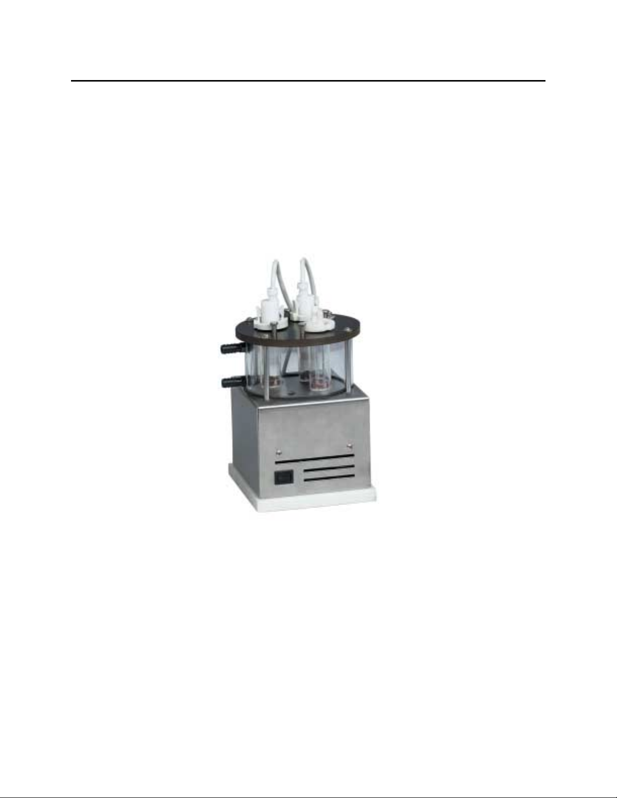
3.1.1 YSI 5301B Bath Assembly
The YSI 5301B Bath Assembly (See Figure 3.1) provides relatively airtight sample chambers
that are stirred magnetically and controlled in temperature when connected to a constant
temperature circulator. The YSI 5301B Bath Assembly is designed to test sample sizes ranging
from 3 to 8 milliliters in volume.
Figure 3.1 YSI 5301B Sample Chamber
The three sample chambers are held in place with locking nylon hold down rings and sealed in
the bath with two rubber o-rings (See Figure 3.2).
The nylon hold down ring also serves as a tensioning device to hold the Lucite plunger in
position while allowing a very fine adjustment regardless of sample size.
The white Lucite plunger has a slanting face and an access slot along the side for removal of gas
bubbles from the sample. The removal of bubbles is of the greatest importance because of the 20
to 1 increase in the amount of oxygen per unit volume in the gas phase over that in saturated
solution.
11
Page 16

The solution level in the access slot should be between the overflow groove and the lower end of
the Lucite plunger. The small amount of unstirred solution in the access slot and around the
Lucite plunger then serves as a barrier to oxygen diffusion into or out of the stirred solution in
the sample chamber. The error caused by diffusion thorough this path is no more than ½ % per
15 minutes for sample chamber oxygen pressures between 50 and 100% of the outside oxygen
pressure. Errors due to oxygen leakage can be minimized by operating with the small possible
oxygen atmosphere, and by limiting the running time of the sample.
If saturating gases other than air are being used, leakage errors may be minimized by flushing the
overflow groove with the saturating gas.
The access slot can also be used for the introduction of samples, inhibitors and activators into the
sample chamber with the aid of a hypodermic syringe.
Stirring is necessary to prevent oxygen depletion by the probe of the solution directly adjacent to
the cathode. The stirring constantly renews the solution in front of the cathode and results in a
steady reading.
In situations where more or less sample agitation is desired other stirrers can be used, the probe
operation should be checked with stirrers interchanged to see that readings are not changed.
Figure 3.2 YSI 5301B Sample Chamber Assembly
12
Page 17

3.1.2 YSI 5304 Micro Adapter Kit
This kit gives the YSI 5301B Bath Assembly greater sensitivity for measuring small sample
volumes (1 milliliter) in experiments where limited sample is available, or where the uptake rate
is low in relation to the total oxygen in the system. Two specially modified Lucite plungers and
magnetic stirrers are included to use with the YSI 5331A Oxygen Probes.
3.1.3 YSI 5356 Micro Oxygen Chamber
The YSI 5356 Micro Oxygen Chamber is designed for a 600-microliter sample and can be
converted to measure a continuous flowing sample. Please refer to your Instech manual for
additional details.
3.2 Setting up your Bath Assembly
The following discussion is based on use of the YSI 5301B Bath Assembly (Figure 3.1 and 3.2),
but it applies generally to any of the bath assemblies offered by YSI.
3.2.1 Warm-up and Equilibrium
When first turned on, most circulators are slow to reach the desired temperature. Allow
sufficient time for the bath assembly to reach temperature before starting measurements.
To minimize the equilibration time, the substrate may be brought to temperature before
introducing the sample. The probe and plunger can be kept at temperature in one of the spare
sample chambers. In this way, meaningful data can be gathered within a minute after sample
introduction.
3.2.2 Saturation of So lution
As an air-saturated solution is heated to the operating temperature of the system, the solution is
automatically kept at saturation by the constant evolution of gas. In such a situation, it is only
necessary to wait 2 or 3 minutes for temperature equilibration.
The appearance of gas bubbles in the sample chamber after the insertion of the Lucite plunger is
an indication that the solution has not completely equilibrated..
Saturation of the solution with oxygen mixtures other air in the YSI 5301B can be achieved (See
Appendix B: Tables). First, the Lucite plunger is withdrawn part way up the sample tube. Then
the saturating gas can be bubbled through the solution and into the space between the Lucite
plunger and the solution (a 0.05” diameter plastic tube will fit down the Lucite plunger through
the access slot). With the stirrer turned on, the solution will saturate in a few minutes. After the
solution has been saturated, the plastic tubing can be withdrawn back into the overflow groove.
Flushing the overflow groove with the saturating gas will prevent the introduction of air into the
sample chamber during the insertion of the Lucite plunger into the solution.
To prevent excessive evaporation, the saturating gas can be bubbled through water before being
introduced into the chamber.
13
Page 18

3.2.3 Position of the Lucite Plunger
The Lucite plunger should be inserted into the sample chamber so as to expel all gas through the
access slot. Bubbles that tend to stick to the Lucite plunger surface can be removed by raising
the plunger to let enough air (or saturating gas) into the sample chamber to gather all the bubbles,
and then reinserting the plunger into the solution to expel the gas.
Solution level in the access slot should be between the lower end of the Lucite plunger and the
overflow groove, See Figure 3.2. It is important that no solution be in the overflow groove
during a measurement. Solution in the overflow groove reduces the amount material being
observed in the sample chamber and increases the liquid surface in contact with the air. A larger
liquid surface increases air diffusion into the solution.
With materials that foam when stirred, twisting the Lucite plunger slightly helps gather small
bubbles at the access slot.
3.2.4 Small Samples, Inhibitors, and Activators
Additions of a few tenths of a milliliter can be made to the sample chamber without removing
the Lucite plunger by using a hypodermic needle inserted down the access slot.
The needle is inserted well into the sample chamber and the injection is made. After the
introduction is completed, the solution level in the sample chamber is lowered so that it is once
again between the overflow groove and the lower end of the Lucite plunger.
When the injection is made, the sample solution in both the needle and the syringe should be free
of air bubbles.
A short length of 0.05” diameter plastic tubing can serve as a flexible extension to the needle.
Teflon tubing is recommended because it is chemically inert and remains stiff at 37°C.
14
Page 19

4. Preparing your Oxygen Probe
When preparing either the 5331 Standard Oxygen Probe or the 5357 Micro Oxygen Probe, you
should take certain precautions to ensure repeatable and reliable performance. Do not touch the
membrane except at its edges where it will not come in contact with the probe’s electrodes. The
oils on your skin can cause contamination. With reasonably careful handling, a membrane can be
expected to last a week or more. Because the membrane is water permeable, the probe tip should
be kept immersed in distilled water after it has been prepared and until it is ready to be used. This
will eliminate the need for frequent recharging of the probe with electrolyte.
When storing the probe for extended periods, rinse and dry it well, then install a new membrane
(no KCl) to protect the electrodes.
The routine daily probe test is described in section 6.2.
4.1 Standard Oxygen Probe
Each YSI 5331A Oxygen Probe comes with a YSI 5775 Standard Membrane/KCl Kit. The YSI
5331A Oxygen Probe is designed to be used with the 5301B Bath Assembly.
The YSI 5350 Membrane Mounting Kit (Figure 4.1) is used to install membranes on the 5331A
Oxygen Probe.
Figure 4.1
The 5775 Standard Membrane/KCl Kit contains two packs of membranes. Each pack contains 15
of 0.001″ FEP Teflon membranes and a squeeze bottle containing dry KCl for preparing the
electrolyte.
15
Page 20

The 5776 High Sensitivity Membrane/KCl kit contains two packs of membranes. Each pack
contains 15 of 0.0005” FEP Teflon membranes. These membranes allow twice the sensitivity of
the 5775 Standard Membrane Kit. This kit also includes the squeeze bottle containing dry KCl
for preparing the electrolyte.
Preparing the probe/ Membrane Installation :
The following instructions describe the probe’s preparation using the YSI 5350 Membrane
Mounting Kit (Figure 4.1) supplied with the bath.
1. Fill the squeeze bottle (marked O2 Probe Solution) with distilled water and shake until the
KCl crystals are completely dissolved.
2. Remove the rubber o-ring and membrane from the probe.
3. Place a new membrane over the unflared end of the brass membrane holder.
4. Slip the large rubber o-ring from the Membrane Mounting Kit down over the membrane
and membrane holder to form a “drum” (the membrane should be taut with no wrinkles).
5. Place the o-ring from the probe over the small end of the o-ring applicator and slide it to
the large end.
6. Seat the probe (cable end down) firmly into the slot in the front face of the probe holder.
The probe should rest on the bottom of the slot.
7. Wet the whole tip of the probe, including the o-ring grove, with electrolyte solution (there
should be no bubbles in the electrolyte on the probe).
8. Position the membrane holder (membrane up) directly over the probe. Pass the membrane
holder down over the probe until it rests on the probe holder. The membrane should now
be stretched over the end of the probe and be wrinkle free.
9. Keeping the membrane tight, place the large end of the Teflon o-ring applicator down
against the end of the probe and push the rubber o-ring down off the applicator and onto
the probe until it seats in the o-ring grove.
10. Remove the large rubber o-ring from the membrane holder and slip the holder off the
probe by raising it straight up. Be careful not to disturb the membrane.
11. Inspect the probe carefully. The membrane should be free of wrinkles and holes. No air
bubbles should be present under the membrane (a loupe or microscope will aid this
inspection).
12. Cut off the excess membrane material close to the rubber o-ring with scissors.
13. Rinse the excess KCl solution from the outside of the probe with distilled water.
14. Wet the rubber o-ring on the probe with distilled water and insert the probe into the
plunger supplied with the bath assembly.
15. By hand, screw the nylon probe clamp into the plunger until it is snug (Do Not
Overtighten). The rubber o-ring can be observed through the Lucite plunger. A black ring
16
Page 21

will appear and widen as the clamp is tightened. Inspect this black ring for continuity (a
true seal is required). If the membrane has not been properly trimmed, it could interfere
with the seal.
4.2 Micro Oxygen Probe
Please refer to the Instech Laboratories Model 125/05 manual for instructions for preparing the
YSI 5357 Micro Probe.
17
Page 22

5. Operating your Oxygen Probe
5.1 Principles of Operation
A Clark type oxygen probe is used in this complete polarographic system. A thin membrane
stretched over the end of the probe isolates the electrodes from the environment. The membrane
is permeable to gases and allows them to come in contact with the probe face. When a suitable
voltage is applied across the electrodes, oxygen will react at the cathode causing a current to
flow. The current is proportional to the amount of oxygen that permeates the membrane. The
probe actually measures oxygen pressure. Since oxygen is rapidly consumed at the cathode, it
can be assumed that the oxygen pressure inside the membrane is zero. Thus, the force causing
the oxygen to diffuse through of oxygen outside the membrane. If the oxygen pressure
increases, more oxygen diffuses through the membrane and more current flows through the
electrodes. A lower pressure results in less current. Diffusion thorough the membrane is directly
proportional to pressure. The oxygen pressure/probe current relationship is stoichiometric.
That is, the relationship between external oxygen pressure and probe current is linear.
The YSI 5331A Standard Oxygen Probe contains a .025” diameter platinum cathode and a silver
anode encased in an epoxy block. The 5357 Micro Oxygen Probe contains a epoxy body
covered with a silver anode sleeve. These configurations facilitate cleaning, minimize the
volume of filling solution required, and insure membrane tension. A Teflon membrane is
secured with a rubber o-ring.
5.2 Electrical Characteristics
The current output of the probe is dependent upon the cathode area and the permeability of the
membrane directly above the cathode. Individual probe variations can be attributed to differences
in membrane characteristics; both film irregularities and variations of installation methods
contribute to such differences. Variations of +/- 10% may be experienced with membranes from
the same package. Wider variations should be suspect. Look for gross membrane imperfections,
membrane rupture or damage during installation.
5.3 Voltage Plateau
When the system is operating correctly, the current output of the probe is nearly flat between 0.6
to 0.8 volts input. A long, flat “plateau” region permits current to be relatively independent of
applied voltage, and results in linearity of output signal for a wide range of oxygen pressures.
The probes are operated with a polarizing voltage of 0.8 VDC. The plateau specification is that
the output signal shall change less than 3% when polarizing voltage is lowered to 0.7 VDC. In
terms of system performance, this translates to a departure from linearity of less than 0.2%, at
worst case conditions.
The TEST function of the YSI 5300A provides a means for checking the plateau. (See Sec. 6.2
Daily Probe Test for additional instructions.)
The plateau test should show a change of less than 3% for new and freshly cleaned probes.
Determine this by comparing the displayed values at AIR (0.8 volts) and TEST (0.7 volts).
Probes showing slopes of 5 to 8% (older probes or those needing cleaning) may prove entirely
serviceable. Check the probe recovery time when subjected to a step change in the polarizing
18
Page 23

voltage (make the observation when changing from the AIR to the TEST position). The signal
should be within 3% of the AIR value 2 ½ minutes after switching.
5.4 Noise
Noise can be attributed to many parts of the system, to poor grounding, to pick-up from high
voltage machines, etc., but two kinds of noise can originate from the probe.
a) The occasional burst or spike occurring frequently but randomly. Check a second probe; if
both probes behave in the same way, the trouble is probably elsewhere.
b) Continual noise of several percent of full scale which may increase in magnitude with time.
The membrane may be in perfect condition. The silver anode may not be not be making a
good reference contact with the solution. Cleaning with ammonia is recommended. (See
Probe Care and Maintenance Sec. 5.9 )
If the noise originates in the probe, a damaged membrane may be the cause (folds or creases in
the membrane are always suspect). Examination of the probe under a low power microscope or
a jeweler loupe can be useful. Check for holes, creases, KCl growths, or drying out under the
membrane.
5.5 Temperature
The current from the probe is highly dependent on the temperature, and in particular, the
temperature of the membrane adjacent to the cathode as well as the sample chamber temperature.
The permeability of the membrane is temperature sensitive. The FEP Teflon membrane has a
temperature coefficient of permeability of 2%/°C. Accurate temperature control is therefore
required, and temperature equilibrium time must be considered when making changes in the
setup. An additional 2%/°C change occurs in a sealed sample chamber because of the change in
oxygen solubility. So, it can be seen that a 1°C change in temperature can cause a change of as
much as 4% from the 100.0% calibration value.
When the nature of the experimental samples necessitates measurement of temperatures from
5°C to 15°C, it is recommended that the Model 5301B Bath Assembly be used. At these lower
temperatures it will be necessary to use a more sensitive membrane due to the lower oxygen
content in your sample. It is recommended that the YSI 5776 KCl and High Sensitivity
Membrane Kit be used. The membranes that come in this kit are 0.0005” thick and allows twice
the sensitivity of the 5775 Standard Membrane Kit.
5.6 Oxygen Consumption by the Probe
The polarographic probe consumes oxygen.
O
The rate of oxygen consumption by the probe is in direct proportion to the current produced by
the electrodes. The most practical way to minimize the errors due to oxygen consumption by the
probe is to use a small area cathode.
A probe current of 1 microamp is equivalent to 8.3 X 10⁻¹¹ grams of oxygen per second
consumed by the probe.
+ 2H2O + 4e = 4 OH-
2
19
Page 24

The YSI 5331 Standard Oxygen Probe has a probe current of about 0.33 microamps in air at
37°C. For a biological system containing 19 micrograms of oxygen (3 milliliters at 37°C), about
0.13% error would accrue per 15 minutes of operation. The YSI 5357 Micro Oxygen Probe has
a probe current of about 0.018 microamps in air at 37°C. For biological systems containing 3.8
micrograms of oxygen (0.6 milliliters at 37°C) about 0.04% error would accrue per 15 minutes
of operation.
For most work, the errors described above can be neglected, but when using very small samples
or conducting experiments for extended periods, significant offsets may accumulate.
5.7 Electrolyte Saturation and Bubbles in Electrolyte
The oxygen probe must be considered a part of the total system under study. For example, the ½
saturated KCl electrolyte which fills or covers the probe has a definite volume and contains
dissolved gases including oxygen (only the electrolyte covering the platinum cathode is free of
oxygen). The amount of oxygen “stored” in the electrolyte depends on the volume of the
electrolyte and its immediate history.
When the oxygen level of the sample is decreased during a run, oxygen is induced to leave the
electrolyte, pass through the membrane and enter the sample, thus introducing possibility
significant errors.
The YSI 5331 Standard Oxygen Probe has an electrolyte volume of 2 to 3 microliters while the
YSI 5357 Micro Oxygen Probe has less than 1 microliter. Errors caused by oxygen in the
electrolyte in either probe, therefore, may be disregarded except for very small samples.
More serious is the presence of gas bubbles under the membrane. Volume for volume, an air
bubble contains 20 times more oxygen than air-saturated water. Thus, if a large gas bubble is
present, significant error can occur with normal size samples. Furthermore, since equilibrium
must be attained by diffusion thorough the membrane, the system may be sluggish and exhibit
slow drifts.
5.8 Drift of Calibration
A probe in good condition operating in a well-controlled environment will typically exhibit drifts
of less than 5% per hour. A drift rate of only 1 % per hour is not uncommon, but external factors
influence the test and some of them are difficult to identify or control.
Factors that may influence the drift rate of the system: changes in air composition in the
laboratory (barometric pressure changes, sudden changes in humidity), mold or bacteria breeding
in a solution that has been left in the chamber, or organic material picked up by the probe (as
from hands, or from contract with the bench).
5.9 Probe Care and Maintenance
When properly used, the YSI 5331A Oxygen Probe requires very little maintenance. It may
occasionally be necessary to clean the silver anode to remove contamination. To clean the anode,
immerse the probe in a 1:1 solution of ammonia and distilled water for 10 to 60 seconds, then
wipe it dry with a cotton tipped swab. Only clean the probe when necessary.
20
Page 25

The platinum cathode requires servicing after long periods of use. The plateau within which the
cathode is mounted must be kept flat and smooth. To re-establish this surface, the probe end
should be rubbed in a circular motion on a wet frosted microscope slide. Wet the slide with
distilled water, use special care to keep the probe body perpendicular to the slide and rotate the
probe in only one direction, either clockwise or counterclockwise.
Store the probe for short periods submersed in distilled water. For extended periods, clean well
and cover with a membrane (no KCl).
21
Page 26

6. Operating your Oxygen System
For practical purposes, calibration of 100% saturation in air saturated water or in an experimental
medium such as Ringers solution at known temperature and pressure and of known composition,
will provide reliable, accurate and repeatable results. The oxygen depletion assay described in
section 6.3 is based on a calibration in air-saturated water at the same pressure and temperature
as the sample. Where comparative results are sought, the procedures described above will
provide reliable, accurate and repeatable results. However, if absolute values under specific
conditions are needed, numerous factors affecting measurement must be carefully controlled.
The ability of a liquid to hold oxygen (or any gas) varies according to three important
parameters: its constitution, its temperature and the ambient pressure. Oxygen solubility
decreases as the salt content or temperature of a solution increases. The tables in Appendix D
will provide data to help calculate oxygen solubility.
The probe membrane itself has a temperature coefficient of 2%/°C, while temperature changes in
a sample chamber sealed by an inserted probe can cause another 2%/°C change in oxygen
solubility. Barometric variation between the normal daily extremes (25 mm in a 760 mm scale)
can cause 3% of change. (A 343 meter elevation above sea level will cause as much as a 4%
decrease in oxygen solubility. See Appendix B.)
It is important for the experimenter to be aware that “100% oxygen saturation” can mean very
different things not only for different solutions, but for the same solution under different
conditions.
6.1 Calibrating
BEFORE YOU CALIBRATE you must setup the monitoring system, as discussed in the
Installation and Initial Setup section of this manual, and prepare the oxygen probe as discussed
in the probe operations section.
Dissolved oxygen calibration must be done in an environment with a known oxygen content.
Two such environments will be discussed here: calibration in air saturated water (AIR dial
setting) and calibration in oxygen saturated water (O2 dial setting). Choose one which best fits
your application and set each channel dial to the appropriate setting.
This section is intended for use as a general guide for use of the YSI 5300A Biological Oxygen
Monitor. System operation is as follows:
1. Turn on the circulator and allow sufficient time for it to come to the desired temperature
per your circulator manual instructions.
2. Turn on the 5300A Monitor and the 5301B Bath Assembly stir motor.
3. Into one of the sample chambers of the bath, place 3 mL of air saturated (or oxygen
saturated) distilled water and the magnetic stirrer supplied with the bath.
4. Allow 3 minutes for temperature equilibration then turn off the bath stir motor.
5. Insert the prepared Channel 1 5331 Probe into the sample chamber. Remove all of the air
from the sample chamber through the access slot in the Lucite plunger (a slight twisting of
22
Page 27

the plunger helps gather the bubbles at the access slot). The solution level in the access slot
should be between the lower end of the Lucite plunger and its overflow groove.
6. Rotate the function switch on the 5300A Monitor to AIR, then set the display to read
100.0% for your air saturated distilled water solution (O2 dial setting, 21.0% oxygen
saturated distilled water solution) using the Channel 1 CAL control knob. Turn the CAL
control locking knob clockwise to lock the knob.
7. Set the recorder (if applicable) to full scale. Note that the 5300A Monitor’s recorder output
for 100% is equal to 1.000 volt full scale.
8. Observe system stability as indicated by the recorder trace. The trace should be noise free
and no more drift than ½% in 15 minutes.
9. Repeat above steps for channel 2 calibration.
NOTE: Any result over 199.99% will display OL (over limit) on the display screen.
Zero Oxygen Calibration
In some small volume applications, the accuracy of the calibration can be improved by
performing a zero calibration as all oxygen probes have a small background current, even in the
absence of oxygen (See Sec. 5.6 for additional probe information). For highest accuracy
measurements, a zero calibration should be performed to compensate for the specific background
current of the probe in use.
To calibrate to a true zero, place the probe in a zero oxygen environment and adjust the
calibration value to zero.
A standard method for creating such an zero oxygen environment is to dissolve excess sodium
sulfite (Na2SO3) and a trace of cobalt chloride (CoCl
come from the sample to be measured. (See Standard Methods for the Examination of Water &
Wastewater, method 4500-O G, 19th edition). The addition of a very small amount of sodium
dithionite or sodium borohydride will also remove all oxygen from the sample. Alternatively,
you may place the probe in a sample that has been bubbled with 100% nitrogen gas. After using
these agent the chamber should be cleaned immediately and thoroughly. It may be necessary to
change the electrode membrane before some studies are conducted.
1. Place this zero oxygen sample in the temperature controlled YSI 5301B Bath Assembly
sample chamber and allow the probe to equilibrate.
2. Press the [MENU] soft-key and the following screen will be displayed.
Left Channel Zero Calibration
Press the up and
down ke ys to zero
adjust the reading
0.0
%AIR
in water. Preferably, the water should
2)
Press MENU to conti nue
23
Page 28

1. After the readings are stable, press the [▲] up soft-key or the [▼] down soft-key to enter the
calibration value of 0.0%.
2. Press the [MENU] soft-key and following screen will be displayed.
Right Channel Zero Calibration
Press the up and
down ke ys to zero
adjust the reading
Press MENU to conti nue
1. If applicable, after the right channel readings are stable, press the [▲] up soft-key or the [▼]
down soft-key to enter the calibration value of 0.0%.
NOTE: When you change the zero point calibration, you offset the other calibration value,
so after zeroing the probe for zero oxygen , you must recalibrate in an oxygen environment.
After ~15 seconds of inactivity the YSI 5300A will reset to the main display, but the zero point
calibrations will remain active.
0.0
%AIR
6.2 Daily Probe Test
(Does not have to be repeated from each measurement).
a. After calibration, set the 5300A Monitor function switch to AIR and wait until the
recorder traces a steady value.
b. Unlock the CAL control knob, set the reading to 90.0% and relock the knob.
c. Turn the function switch counterclockwise to the TEST position and wait for a steady
trace.
d. The test trace should be no lower than 87.0% of full scale after 2.5 minutes. (See Sec.
5.3, Voltage Plateau for additional information) If the probe does not meet this
specification, the membrane should be replaced (see section 4.1). If performance still
does not improve, the probe should be cleaned (see Probe Care and Maintenance, Sec.
5.9).
After performing the probe test and determining that the probe is functioning correctly, turn the
function switch to the AIR position, unlock the Cal control knob and reset the display to 100.0%.
Lock the CAL control knob. Repeat above steps for channel 2 daily probe test.
6.3 Sample Monitoring
After calibration and the daily probe test your system is ready to monitor oxygen.
1. Turn off the 5301B Bath stir motor and place a 3 mL sample and a magnetic stirrer into the
sample chamber.
2. Turn on the 5301B Bath stir motor. Allow 3 minutes for temperature equilibration, then turn
the 5301B Bath stir motor off.
3. Insert a prepared probe into this sample chamber as in step 5.
24
Page 29

4. Allow from 2 to 15 minutes for the recorder to produce a trace defining the oxygen uptake
curve.
5. Determine the actual oxygen consumption rate as illustrated in the following example:
An air saturated sample of Ringers solution at 1 atmosphere and 37°C contains 5.02 µL O2/mL
(see Table 1). Therefore, a 3 mL sample contains 5.02 µL O2/mL x 3 mL = 15.06 µL O2. If the
oxygen concentration were to change from 82% to 64% in 5 minutes, the air saturation would
have been reduced by 18%.
A change of 18% = 2.71 µL O2. On an hourly basis, 2.71 µL O2 x 12/hr = 32.52 µL/hr.
6. To remove a magnetic stirrer from a sample chamber, use the magnet retriever (YSI 5225)
supplied with the 5301B Bath Assembly.
NOTE: Any result over 199.99% will display OL (over limit) on the display screen.
25
Page 30

7. Troubleshooting
Problem/ Symptoms Possible Cause Correction
YSI 5300A Biological
Monitor
Blank Display Power supply not connected Connect power supply
Data not logging on chart
recorder
Chart recorder not connected
Refer to chart recorder manual
Data not logging via RS232
serial port connection
Serial cable not connected Connect serial cable
Serial cable is faulty Replace cable
Monitor and data acquisition
Chart recorder unplugged Connect power supply
Connect recorder with monitor
with YSI 5300A Monitor
for further direction
RS232 Serial Output not
turned on
system not setup correctly
Correct monitor setup
Check and compare monitor
and data acquisition software
setup
Test setting greater than 3% of
Air/ O2 value 2 ½ minutes
after switching
KCl solution has bubbles Install new YSI Teflon
Probe face fouled Clean probe face, see Sec. 5.9
Air bubbles on membrane Slightly twist plunger to
Temperature fluctuations Use appropriate temperature
Improper stirring Check stirring
Slow probe response Membrane integrity failure Install new YSI Teflon
KCl solution has bubbles Install new YSI Teflon
Membrane integrity failure Install new YSI Teflon
membrane and fresh KCl
solution, sec.
membrane and fresh KCl
solution, sec.
remove bubbles at access slot
controlled circulator with
water bath, see Sec. 5.5
membrane and fresh KCl
solution, sec.
membrane and fresh KCl
26
Page 31

solution, sec.
Probe face fouled Clean probe face, see Sec. 5.9
Display values not changing
Oxygen probes not plugged in Connect oxygen probes
when exposed to oxygen
Calibration drift Membrane and KCl solution
failing
Install new YSI Teflon
membrane and fresh KCl
solution, sec.
Probe face fouled Clean probe face, see Sec. 5.9
See Sec. 5.8 for further
direction
Readings inconsistent Membrane and KCl solution
failing
Install new YSI Teflon
membrane and fresh KCl
solution, sec.
Probe face fouled Clean probe face, see Sec. 5.9
Air bubbles on membrane Slightly twist plunger to
remove bubbles at access slot
Temperature fluctuations Use appropriate temperature
controlled circulator with
water bath, see Sec. 5.5
Improper stirring Check stirring
YSI 5301B Bath Assembly
Magnetic stirrers not moving YSI 5301B power supply not
Connect power supply
connected
Debris or residue
accumulation
Clean sample chamber and
magnetic stirrer with
isopropanol
Replace magnetic stirrer
27
Page 32

8. Warranty and Repair
YSI 5300A Biological Oxygen Monitors, YSI 5301B Bath Assembly and YSI 5331A probes are
warranted for one year from date of purchase by the end user against defects in materials and
workmanship. Within the warranty period, YSI will repair or replace, at its sole discretion, free
of charge, any product that YSI determines to be covered by this warranty.
To exercise this warranty, write or call your local YSI representative, or contact YSI Customer
Service in Yellow Springs, Ohio. Send the product and proof of purchase, transportation prepaid,
to the Authorized Service Center selected by YSI. Repair or replacement will be made and the
product returned, transportation prepaid. Repaired or replaced products are warranted for the
balance of the original warranty period, or at least 90 days from date of repair or replacement.
Limitation of Warranty
This Warranty does not apply to any YSI product damage or failure caused by (i) failure to
install, operate or use the product in accordance with YSI’s written instructions, (ii) abuse or
misuse of the product, (iii) failure to maintain the product in accordance with YSI’s written
instructions or standard industry procedure, (iv) any improper repairs to the product, (v) use by
you of defective or improper components or parts in servicing or repairing the product, or (vi)
modification of the product in any way not expressly authorized by YSI.
THIS WARRANTY IS IN LIEU OF ALL OTHER WARRANTIES, EXPRESSED OR I MPLIED, INCLUDING
ANY WARRANTY OF MERCHANTABILITY OR FITNESS FOR A PARTICULAR PURPOSE. YSI’s
LIABILITY UNDER THIS WARRANTY IS LIMITED TO REPAIR OR REPLACEMENT OF THE PRODUCT,
AND THIS SHALL BE YOUR SOLE AND EXCLUSIVE REMEDY FO R ANY DEFECTIVE PRODUCT
COVERED BY THIS WARRANTY. IN NO EVENT SHALL YSI BE LIABLE FOR ANY SPECIAL,
INDIRECT, INCIDENTAL OR CONSEQUENTIAL DAMAGES RESULTING FROM ANY DEFECTIVE
PRODUCT COVERED BY THIS WARRANTY.
YSI Factory Service Centers
United States
YSI Incorporated • Repair Center • 1725 Brannum Lane • Yellow Springs, OH • 45387 • Phone: 937 767-7241 • Fax: 937 767-935 3
Endeco/YSI Inc. • 13 Atlantis Drive • Marion, MA • 02738 • Phone: 508 748-0366 • Fax: 508 748-2543
Europe
YSI LTD • Lynchford House • Lynchford Lane • Farnborough, Hampshire • GU14 GLT • Phone: 441 252 514711 • Fax: 441 252 511855
YSI Authorized Service Centers
California
EviroServices & Repair • 1110 Burnett Avenue, Suite D • Concord, CA • 94520 • Phone: 510 609-1088 • Fax: 510 674-8655
Fisher Scientific ISD • 2822 Walnut Avenue, Suite E • Tustin, CA • 92681 • Phone: 800 395-5442
Florida
Aquatic Eco Systems, Inc. • 1767 Benbow C ourt • Apopka, FL • 32703 • Phone: 407 886-3939 • Fax: 407 886-6787
Georgia
Fisher Scientific ISD • 2775 Horizon Ridge Court • Suwanee, GA • 30174 • Phone: 800 395-5442
Illinois
Fisher Scientific ISD • 1600 West Gleenlake Avenue • Itasca, Ill • 60143 • Phone: 800 395-5442
Maine
Q. C. Services • P.O. Box 68 • Harrison, M E • 04040 • Phone: 207 583-2980 • Fax: 207 583-6936
Mississippi
Aquacenter • 166 Seven Oaks Road • Leland, MS • 38756 • Phone: 601 378-2861 • Fax: 601 378-2 862
CC Lynch and Associates • 212 E. 2nd St reet • Suite 203 • Pass Christian, MS • 39571 • Phone: 601 452-4612 • Fax: 601 452-2563
New Jersey
Fisher Scientific ISD • 52 Fadem Road • Springfield, NJ • 07081 • Phone: 800 395-5442
Oregon
Q. C. Services • P.O. Box 14831 • Portland, OR • 97293 • Phone: 503 236-2712 • Fax: 503 235-2535
Pennsylvania
Fisher Scientific ISD • 585 Alpa Drive • Blawnox, PA • 15238 • Phone: 800 395-5442
28
Page 33

8.1 Cleaning Instructions
NOTE: Before they can be serviced, equipment exposed to biological, radioactive, or toxic
materials must be cleaned and disinfected. Biological contamination is presumed for any
instrument, probe, or other device that has been used with body fluids or tissues, or with waste
water. Radioactive contamination is presumed for any instrument, probe or other device that has
been used near any radioactive source.
If an instrument, probe, or other part is returned or presented for service without a Cleaning
Certificate, and if in our opinion it represents a potential biological or radioactive hazard, our
service personnel reserve the right to withhold service until appropriate cleaning,
decontamination, and certification has been completed. We will contact the sender for
instructions as to the disposition of the equipment. Disposition costs will be the responsibility of
the sender.
When service is required, either at the user's facility or at YSI, the following steps must be taken
to insure the safety of our service personnel.
1. In a manner appropriate to each device, decontaminate all exposed surfaces, including any
containers. 70% isopropyl alcohol or a solution of 1/4 cup bleach to 1 gallon tap water are
suitable for most disinfecting. Instruments used with waste water may be disinfected with
.5% Lysol if this is more convenient to the user.
2. The user shall take normal precautions to prevent radioactive contamination and must use
appropriate decontamination procedures should exposure occur.
3. If exposure has occurred, the customer must certify that decontamination has been
accomplished and that no radioactivity is detectable by survey equipment.
4. Any product being returned to the YSI Repair Center, should be packed securely to prevent
damage.
5. Cleaning must be completed and certified on any product before returning it to YSI.
29
Page 34

8.2 Packing Instructions
1. Clean and decontaminate items to insure the safety of the handler.
2. Complete and include the Cleaning Certificate.
3. Place the product in a plastic bag to keep out dirt and packing material.
4. Use a large carton, preferably the original, and surround the product completely with packing
material.
5. Insure for the replacement value of the product.
Cleaning Certificate
Organization
Department
Address
City _______________ State ______ Zip
Country __________________ Phone
Model No. of Device ______ Lot Number
Contaminant (if known)
Cleaning Agent(s) used
Radioactive Decontamination Certified?
(Answer only if there has been radioactive exposure)
___ Yes ___ No
Cleaning Certified By
Name Date
30
Page 35

9. Required Notice
The Federal Communications Commission defines this product as a computing device and
requires the following notice:
This equipment generates and uses radio frequency energy and if not installed and used properly,
may cause interference to radio and television reception. There is no guarantee that interference
will not occur in a particular installation. If this equipment does cause interference to radio or
television reception, which can be determined by turning the equipment off and on, the user is
encouraged to try to correct the interference by one or more of the following measures:
• re-orient the receiving antenna
• relocate the computer with respect to the receiver
• move the computer away from the receiver
• plug the computer into a different outlet so that the computer and receiver are on
different branch circuits.
If necessary, the user should consult the dealer or an experienced radio/television technician for
additional suggestions. The user may find the following booklet, prepared by the Federal
Communications Commission, helpful: "How to Identify and Resolve Radio-TV Interference
Problems." This booklet is available from the U.S. Government Printing Office, Washington, DC
20402, Stock No. 0004-000-00345-4.
31
Page 36

10. Accessories and Replacement Parts
The following parts and accessories are available from YSI or any Franchise Dealer authorized
by YSI.
{PRIVATE }YSI Order
Number
5092 Nylon Hold Down Ring
5093 Lucite Plunger (standard 5301B)
5215 Chamber Pack (6 chambers, 12 O-rings)
5222 Magnetic Stir Bar (standard 5301B)
5225 Magnetic Retriever
5301B Standard Bath Assembly
5304 Micro Adapter Kit
5307 Lucite Plunger (5301B w/5304 Micro Adapter Kit)
5309 Magnetic Stir Bar (5301B w/5304 Micro Adapter Kit)
5310 Constant Temperature Circulating Bath (includes YSI 5315)
5313 Magnetic Retriever
5315 Plumbing Kit (used to connect YSI 5310 with the YSI 5301B)
5320 2 Channel Chart Recorder (includes YSI 5320)
5325 Wire Set (used to connect YSI 5320 with YSI 5300A)
Description
5331A Oxygen Probe
5338 O-ring Applicator
5350 Membrane Mounting Kit
5356 Micro Oxygen Chamber
5357 Micro Oxygen Probe
5358 Cable Assembly
5775 Membrane/KCl Kit, Standard (30 membranes)
5776
5793 Standard Membranes (150 membranes)
5794 High-Sensitivity Membranes (150 membranes)
5945 O-ring Kit (12 O-rings)
052021 RS-232 Cable (used to connect YSI 5300A with data acquisition serial port)
Membrane/KCl Kit, High Sensitivity (30 membranes for higher permeability
below 15ºC
32
Page 37

11. Appendix A - Specifications
YSI 5300A System (YSI 5300A, YSI 5331A, and YSI 5301B)
System Stability: Maximum 5% of full scale per hour at 50% saturation or greater. (Accounts
for probe, temperature, electronic and O2 leak effects.)
System Linearity: ±1% of full scale (full scale is 200%)
Environmental Requirements:
• Laboratory setting
• Ambient temperature 15 to 35° C
• Relative Humidity up to 65% (non-condensing), low signal readings at 90% humidity affects
the readings.
UL3101-1 compliance (5300A and 5301B): Pollution degree 2, Installation category 2
YSI 5300A Monitor
Channels: Each of the two channels are independently operated and each channel has a
dedicated 0 to 2.000 Volt recorder output. Each channel has two input jacks, one for the
standard probe and one for the micro probe.
Display: LCD, oxygen results displayed in % oxygen saturation, four digits maximum with a
resolution of 0.1%
Instrument Size: 15.8 H x 28.5 W. x 22 D cm, 2.4 kg
6.2 H x 11.2 W x 8.7 D in, 5.3 lb
Power: 115 vac ±10%, 60 hz, 0.16 amp
230 vac ±10%, 50 hz, 0.08 amp
Approval: CE
Size: 9 X 9.5 X 4.4 inches 22.9 X 24.1 X 11.2 cm
Weight: 2.6 pounds 1.1 kg
Recorder Output: 0 to 2.000 volts corresponds to full scale. 20 K ohms minimum load
impedance required. The display is tracked within ±0.2% of full scale; the differential output
capability (Channel 1 minus Channel 2) is accurate to ±0.4% of full scale.
33
Page 38

YSI Oxygen Probes
Oxygen Consumption Rate Range: 3 to 250 µL O2/hr in air-saturated solutions;:15 to 250 µL
O2/hr in oxygen saturated solutions.
Probe Linearity: ±1.0% of full scale. (full scale is 200%)
Oxygen Consumption of the 5331A Standard Oxygen Probe: less than 6x10
-7
grams O2/hr
(<0.1 µL 02/hr) in air.
Oxygen Consumption of 5357 Micro Oxygen Probe: less than 6X10
-9
grams O2/hr (<0.005 µL
O2/hr) in air.
Stabilization Time: 60 seconds maximum with probe and solution at operating temperature.
Response Time: 90% of final reading in approximately 10 seconds (± 2 seconds). Assumes
probe and solution are at operating temperature.
YSI 5301B Bath Assembly
Sample Chamber Size: 600 µL with the 5357 Micro Oxygen Probe, 1 mL with YSI 5304 Micro
Adapter Kit and 3 to 8 mL with 5331 Standard Oxygen Probe.
Temperature Stability: With suitable circulator, ±0.02°C of circulator temperature in the
sample chamber.
Stirring Speed: 480 RPM with 5301B Standard Bath and variable to 1600 RPM with 5356
Micro Oxygen Chamber
Sample Temperature Range: 5 to 40°C
Approvals: 115V 5301B: UL
230V 5301B: CE
34
Page 39

12. Appendix B – Tables
Volume of Oxygen Dissolved in Aqueous Medium
(microliters of oxygen per milliliter at 1 atmosphere)
Temp ºC
15
20
25
28
30
Equilibrated with 100% O2 Equilibrated with 21% O
H2O
34.2
31.0
28.5
26.9
26.1
1
Ringers Solution2
34.0
31.0
28.2
26.5
26.0
H2O2
7.18
6.51
5.98
5.65
5.48
Ringers Solution2
7.14
6.51
5.92
5.56
5.46
2
35
37
40
1
From “Handbook of Chemistry and Physics” 40th Ed., Chemical Rubber Pub. Co., Cleveland,
24.5
23.9
23.1
24.5
23.9
23.0
5.14
5.02
4.85
5.14
5.02
4.83
1958-1959.
2
Recalculated from Umbriet et al (1964). “Manometric Methods”, 4th Ed. Burgess Pub. Co.
35
Page 40

Solubility of O2 in Buffered Mitochondrial Medium Equilibrated with Air (20.9 % O2)
Temperature ºC µg atoms O2/ mL 3 µMoles/ mL (mM)
15
20
25
30
35
37
40
0.575
0.510
0.474
0.445
0.410
0.398
0.380
0.288
0.255
0.237
0.223
0.205
0.199
0.190
3
Solubility of O2 experimentally determined by Chappell (1964) “Biochem.” J. 90, 225., in a
buffered mitochondrial medium containing NADH2 inorganic phosphate, and isolated
mitochondria.
36
Page 41

Bunsen Coefficients for Solubility of Oxygen in Plasma and Blood 4
Blood Hb g/ 100mL
Temperature
ºC
15
20
25
28
30
Plasma
0.0302
0.0277
0.0257
0.0246
0.0238
5g
0.0310
0.0282
0.0261
0.0249
0.0241
10g
0.0312
0.0284
0.0263
0.0251
0.0243
15g
0.0316
0.0287
0.0265
0.0253
0.0245
20g
0.0323
0.0293
0.0271
0.0259
0.0251
35
37
40
0.0220
0.0214
0.0208
0.0226
0.0220
0.0211
0.0227
0.0221
0.0212
0.0229
0.0223
0.0214
0.0234
0.0228
0.0219
4
From Christofordes et al “J. Appl. Physiol.” 26:56, 1969 and “J. Appl. Physiol.” 27:592, 1969.
37
Page 42

Solubility of Oxygen in Water and Various Solvents
Relative Solubility
Effect of Certain Electrolytes on Solubility =
Solubility Concentration Per Unit M
Solvent Solubility at 20°C
Concentration
1 M NaCl 0.724 NaCL 0.0073
1 M KCl 0.737 KCl 0.0069
1M HCl 0.932 KF 0.0078
½ M H2SO
4
1 M KOH 0.670 1/3 X K3Fe(CN)
1 M NaOH 0.662 ½ X K2C2O
1 M Sucrose 0.554 NaH2CO
Methyl Alcohol 7.670 ½ Na2CO
0.894 NaNO
2
6
4
3
3
0.0053
0.0060
0.0071
0.0081
0.0085
Ethyl Alcohol 7.700 NaOH 0.0090
Acetone 6.910 Lactic Acid 0.0003
Sources:
Sendroy, Dillion & Van Slyke, “J. Biol. Chem.” 105:597, 1939.
Van Slyke et al, “J. Biol. Chem.” 78:765, 1928.
Handbook of Respiration, Wright Air Development Center Report, 58-352, Page 6.
38
Page 43

Atmospheric Pressure Vs. Altitude Correction
Altitude
Atmospheric Pressure (mm Hg) Feet Meters Correction Factor
768 -276 -84 101
760 0 0 100
752 278 85 99
745 558 170 98
737 841 256 97
730 1126 343 96
722 1413 431 95
714 1703 519 94
707 1995 608 93
699 2290 696 92
692 2587 789 91
684 2887 880 90
676 3190 972 89
669 3496 1066 88
661 3804 1160 87
654 4115 1254 86
646 4430 1350 85
638 4747 1447 84
631 5067 1544 83
623 5391 1643 82
616 5717 1743 81
608 6047 1843 80
600 6381 1945 79
593 6717 2047 78
585 7058 2151 77
578 7401 2256 76
570 7749 2362 75
562 8100 2469 74
555 8455 2577 73
574 8815 2687 72
540 9187 2797 71
Derived from the 16th Edition of “Standard Methods for the Examination of Water and Wastewater”.
39
Page 44

13. Appendix C - Required Notice
The Federal Communications Commission defines this product as a computing device and
requires the following notice:
This equipment generates and uses radio frequency energy and if not installed and used properly,
may cause interference to radio and television reception. There is no guarantee that interference
will not occur in a particular installation. If this equipment does cause interference to radio or
television reception, which can be determined by turning the equipment off and on, the user is
encouraged to try to correct the interference by one or more of the following measures:
• re-orient the receiving antenna
• relocate the computer with respect to the receiver
• move the computer away from the receiver
• plug the computer into a different outlet so that the computer and receiver are on
different branch circuits.
If necessary, the user should consult the dealer or an experienced radio/television technician for additional
suggestions. The user may find the following booklet, prepared by the Federal Communications Commission,
helpful: "How to Identify and Resolve Radio-TV Interference Problems." This booklet is available from the U.S.
Government Printing Office, Washington, DC 20402, Stock No. 0004-000-00345-4.
40
Page 45

14. Appendix D: Application Notes
Application notes for the YSI 5300A are currently under development. For a current listing,
please contact YSI Life Sciences Customer Service (800-659-8895 or 937-767-7241 extension 2)
or visit the YSI Website at www.YSI.com.
41
Page 46

15. Appendix E: Gas Solubility Relationships
Gas Solubility Relationships
µg/ mL= 0.031 µMole/mL
µg/ mL= 0.700 µL/ mL at 0ºC
µM/ mL= 32.000 µg/mL
µM/mL= 22.400 µL/mL
1 µL/mL= 1.430 µg/ml at 0ºC
1 µL/mL= 0.045 µMole/mL at 0ºC
To correct for temperatures other than 0ºC when using values in microliters:
µL at 0ºC X [(273 + TºC) / 273] = µL at TºC
Sources:
Sendroy, Dillon & Van Slyke, op cit.
Van Slyke et al, op cit.
Handbook of Respiration, op cit.
42
Page 47

16. Appendix F: Interfering Gases
H2S, SO2, halogens, nitrous oxide and CO are interfering gasses. If you suspect erroneous
readings, it may be necessary to determine if these are the cause. The following gases have been
tested for response.
100% Carbon Monoxide Less than 1%
100% Carbon Dioxide Less than 1%
100% Hydrogen Less than 1%
100% Chlorine 2/3 O2 response
100% Helium None
100% Nitrous Oxide 1/3 O2 response
100% Ethylene None
100% Nitric Oxide 1/3 O2 response
43
Page 48

1725 Brannum Lane
Yellow Springs, Ohio 45387 USA 530035
937 767-7241 • 800 659-8895 • Fax 937 767-8058 A530035 Rev A
Info@ysi.com • www.YSI.com May 02
2002 YSI Incorporated
 Loading...