

Page 1
YSI Environmental
Pure Data for a Healthy Planet.
®
YSI 5200
Recirculating System Monitor
Operations
Manual
Page 2

Page 3

Table of Contents
SECTION 1. SAFETY ........................................................................................................................3
1.1 GENERAL SAFETY INFORMATION................................................................................................3
SECTION 2. INTRODUCTION........................................................................................................5
SECTION 3. INSTALLATION .........................................................................................................9
3.1 UNPACKING AND INSPECTION .....................................................................................................9
3.2 SELECTING AN INSTALLATION LOCATION................................................................................. 10
3.3 INSTALLING THE COMPONENTS.................................................................................................12
3.4 MOUNT THE YSI 5200 RECIRCULATING SYSTEM MONITOR.....................................................13
3.5 INSTALLING THE 5562 OR 5561 PROBE ASSEMBLIES ................................................................17
3.6 WIRING THE SYSTEM.................................................................................................................20
3.7 COMMUNICATIONS METHOD.....................................................................................................23
3.8 GROUNDING INFORMATION.......................................................................................................26
3.9 SAFETY ISSUES .......................................................................................................................... 26
3.10 LIGHTNING AND SURGE PROTECTION ....................................................................................... 26
SECTION 4. PROBE MODULE .....................................................................................................27
4.1 UNPACKING THE PROBE MODULE .............................................................................................27
4.2 FEATURES OF THE YSI 5561 PROBE MODULE...........................................................................27
4.3 FEATURES OF THE YSI 5562 PROBE MODULE...........................................................................28
4.4 PREPARING THE YSI 5561 PROBE MODULE ..............................................................................28
4.5 PREPARING THE YSI 5562 PROBE MODULE ..............................................................................28
4.6 MEMBRANE CAP INSTALLATION ............................................................................................... 30
4.7 CALIBRATION/STORAGE CUP (5562 ONLY)...............................................................................31
4.8 INSTRUMENT/CABLE CONNECTION ...........................................................................................31
SECTION 5. OPERATION..............................................................................................................33
5.1 RUN SCREEN..............................................................................................................................33
5.2 MAIN MENU............................................................................................................................... 34
5.3 PARAMETERS MENU ..................................................................................................................35
5.4 DAILY CHECKS ..........................................................................................................................57
5.5 CONDUCTING A SYSTEM TEST................................................................................................... 58
SECTION 6. CALIBRATION .........................................................................................................60
6.1 GETTING READY TO CALIBRATE ............................................................................................... 60
6.2 CALIBRATION PROCEDURES ......................................................................................................62
SECTION 7. ALARM/PAGER........................................................................................................73
YSI Incorporated i 5200 Recirculating System Monitor
Page 4

ALARM LOGIC FLOW CHARTS...................................................................................................73
7.1
7.2 GENERAL ALARM ......................................................................................................................77
SECTION 8. NETWORK.................................................................................................................78
8.1 RS485 NETWORK.......................................................................................................................78
8.2 AUXILIARY INPUTS WIRING ......................................................................................................79
SECTION 9. ADVANCED SETUP .................................................................................................82
9.1 SYSTEM MENU........................................................................................................................... 82
9.2 TIMERS MENU............................................................................................................................93
9.3 RELAY OUTPUT WIRING..........................................................................................................100
9.4 AUXILIARY SYSTEM ................................................................................................................102
SECTION 10. AQUAMANAGER SOFTWARE ...........................................................................106
SECTION 11. MAINTENANCE .....................................................................................................107
11.1 PROBE MAINTENANCE AT THE DEPLOYMENT SITE.................................................................107
11.2 CALIBRATION CHECKS ............................................................................................................ 108
11.3 RECOMMENDED QUALITY ASSURANCE PROTOCOL ................................................................108
11.4 SENSOR CARE AND MAINTENANCE .........................................................................................110
11.5 RECOMMENDED CLEANING OF THE 5200 MONITOR AND ACCESSORIES ................................. 114
SECTION 12. STORAGE.................................................................................................................115
12.1 SHORT TERM STORAGE ........................................................................................................... 115
12.2 LONG TERM STORAGE ............................................................................................................. 115
SECTION 13. TROUBLESHOOTING...........................................................................................117
SECTION 14. WARRANTY AND SERVICE INFORMATION .................................................120
SECTION 15. SYSTEM SPECIFICATIONS.................................................................................123
SECTION 16. FACTORY DEFAULT SETTINGS .......................................................................125
SECTION 17. INTERNATIONAL MODEM SUPPORT .............................................................133
SECTION 18. HEALTH AND SAFETY.........................................................................................134
SECTION 19. REQUIRED NOTICE..............................................................................................138
SECTION 20. ACCESSORIES........................................................................................................139
SECTION 21. SOLUBILITY AND PRESSURE/ALTITUDE TABLES .....................................140
SECTION 22. YSI CONDUCTIVITY CALIBRATION SOLUTION VALUES........................144
SECTION 23. DECLARATION OF CONFORMITY ..................................................................145
YSI Incorporated ii 5200 Recirculating System Monitor
Page 5
Section 1. Safety
1.1 General Safety Information
Read all safety information in this manual carefully before using the YSI 5200 Recirculating System
Monitor. Reagents that are used to calibrate and check this instrument may be hazardous to your health.
Take a moment to review Section 18 Health and Safety.
WARNING
Warnings are used in this manual when misuse of the instrument could result in death or serious injury to
a person.
CAUTION
Cautions are used in this manual when misuse of the instrument could result in mild or serious injury to a
person and/or damage to equipment.
IMPORTANT SAFETY INSTRUCTIONS!
Save these instructions for future reference!
The most important safety rule for use of the YSI 5200 is to utilize the instrument ONLY for purposes
documented in this manual. The user should be certain to read all of the safety precautions outlined below
before using the instrument.
WARNING: To avoid severe personal injury or damage to the equipment, installation, operation and
service should be performed by qualified personnel who are thoroughly familiar with the entire contents
of this manual.
WARNING: All wiring involving connections to mains power must be performed by a qualified licensed
electrician, and must conform to all locally applicable electrical codes. Any mains power circuit
connected within the 5200 enclosure must be protected by a Ground Fault Circuit Interrupt device. Do not
make connections while power is applied. Disconnect power before proceeding. See Section 3.6 Wiring
the System.
WARNING: The 5200 utilizes sensitive solid state devices that can be damaged by static shock.
Installers must observe accepted ESD, E
the 5200 I/O plate or damage may result. See Section 3.6 Wiring the System.
CAUTION: It is essential that all sensor wiring be run in a separate cable or conduit from power wiring.
See Section 3.6 Wiring the System.
CAUTION: The YSI 5579 power supply accessory is for indoor use only, and must be connected to the
5200 Monitor with a suitable waterproof extension cable if the 5200 Monitor is installed in a damp
location. See Section 3.6.1 DC Power Input Wiring.
WARNING: A UL Listed DC power supply is required for any installation which is connected to “mains
supply” or other power source which is “hazardous live” per UL 3101-1 section 3.5.2. See Section 3.6.1
DC Power Input Wiring.
lectro-Static Discharge, procedures while connecting cabling to
YSI Incorporated 3 5200 Recirculating System Monitor
Page 6
WARNING: A UL Listed slow-blow fuse with a maximum current rating of 1A must be connected in
series with the positive terminal of any power supply not provided by YSI. See Section 3.6.1 DC Power
Input Wiring.
CAUTION: Power supply voltage above 16.5VDC may permanently damage the 5200 Monitor. See
Section 3.6.1 DC Power Input Wiring.
CAUTION: The sensitivity and stability of the monitor will be impaired if the monitor is not grounded.
Do not
Grounding Information.
CAUTION: Do not ground the probe body. See Section 3.6 Wiring the System.
WARNING: Turn off all power and assure power “lockout” before servicing to avoid contact with
electrically powered circuits. See Section 3.6 Wiring the System.
CAUTION: Section 3.10 Lightning and Surge Protection or any other installation procedure cannot
protect against a direct lightning strike. YSI Incorporated cannot accept liability for damage due to
lightning or secondary surges.
apply power to the Monitor until all electrical connections are verified and secure. See Section 3.8
YSI Incorporated 4 5200 Recirculating System Monitor
Page 7

Section 2. Introduction
Congratulations on your purchase of a sophisticated, yet easy-to-use aquatic environment controller.
Designed with a powerful INTEL
Monitor/Controller includes the following features:
Ö Continuous monitoring of Dissolved Oxygen (DO), conductivity, salinity, temperature, pH and
Oxidation Reduction Potential (ORP).
Ö Menu-driven programming environment.
Ö 4 Relay outputs
Ö Aux. I/O system supporting 2 Inputs (1 Digital, 1 Analog/Digital)
Ö FLASH memory that makes upgrading your YSI 5200 Recirculating Monitor with new software
a simple task.
Ö Local audible alarm or optional remote dialup pager alarm capability.
Ö Parameter control capability for controlling peripheral equipment such as pumps, and lighting.
Ö Powerful data logging capability that stores up to 30-days of data.
Ö Communications ports supporting both direct and modem connectivity. RS232, TCP/IP
connectivity and a network communications port allowing multiple YSI 5200 Recirculating
Monitors to be connected via an RS485 network.
Ö Wide operating power range (7–16VDC) along with 12VDC battery backup capability.
™
Ö AquaManager
—Software that allows you to communicate with your YSI 5200 Recirculating
Monitor, perform advanced graphical analysis of current and historical data—from any
Windows 2000/XP PC.
™
microprocessor, your YSI 5200 Recirculating System
The YSI 5200 is constructed with only the highest quality components. All information gathered by the
controller is processed digitally. The YSI 5200 architecture includes Digital Signal Processing (DSP)
hardware and software that guarantees accurate and repeatable readings over the life of the YSI 5200.
Monitoring Capability
The YSI 5200 software provides for monitoring, control, and alarm capabilities. The five water quality
parameters monitored and controlled are:
Ö Dissolved Oxygen
Ö Conductivity
Ö Temperature
Ö pH
Ö ORP
In addition to the five parameters the YSI 5200 also provides two auxiliary inputs that can be configured
to provide 2 digital inputs or 1 digital input and 1 analog input for sampling a recorder output from
another instrument.
The probe is connected to the YSI 5200 through a waterproof connector (see Figure 4-10 Bottom
Connectors).
Ports for up to three non-metallic watertight compression or conduit fittings are located on the 5200
bottom panel and provide the means for connecting power, relay outputs and communications via the I/O
plate located within the 5200 Monitor. The 5200 Monitor is supplied with compression fittings; conduit
fittings are available as an accessory.
YSI Incorporated 5 5200 Recirculating System Monitor
Page 8
Front Panel
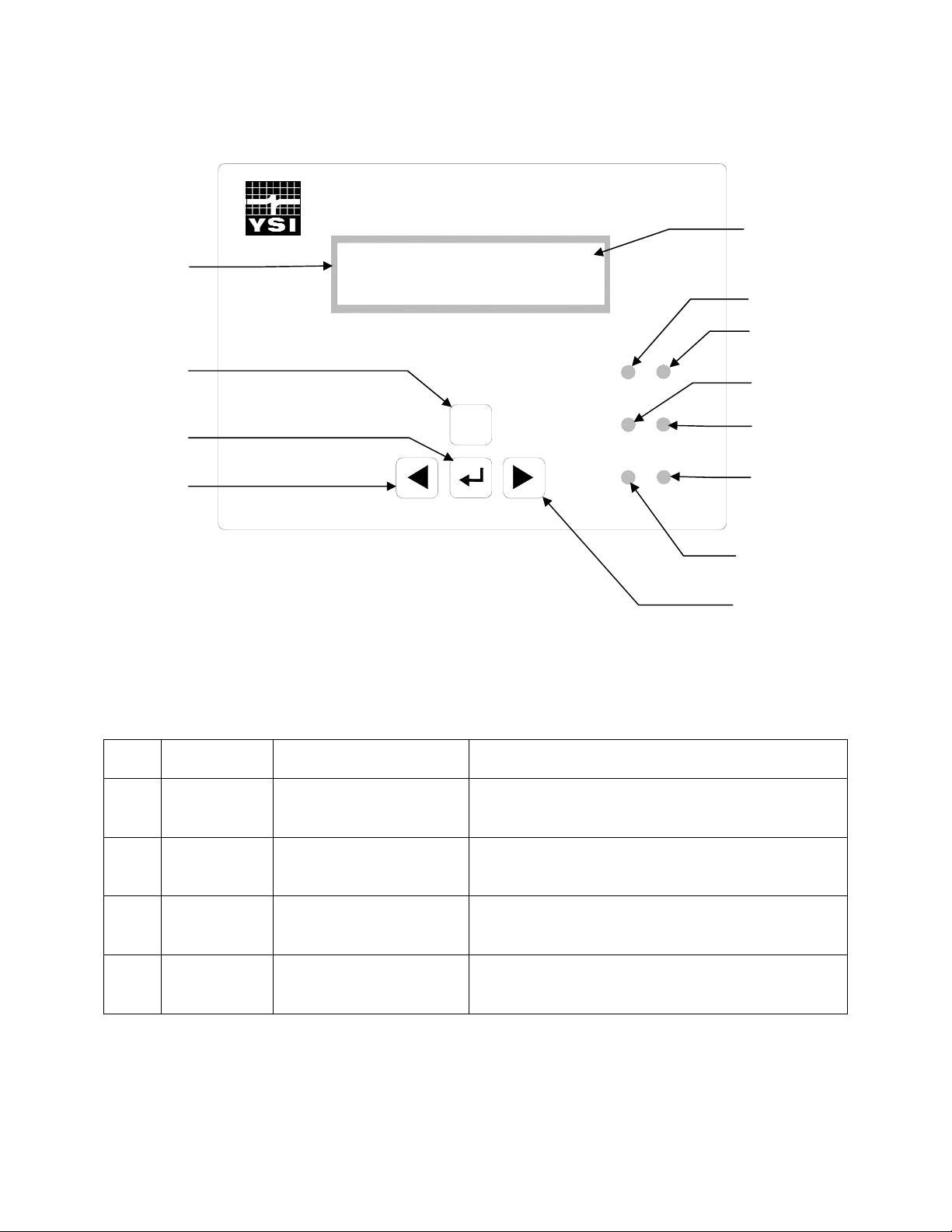
The front panel of the 5200 contains the display and keypad as shown in Figure 2-1 Front Panel.
Display
Escape key
Enter key
Left Arrow key
DO 6.57 mg/L H
Cond 7.63mS *
ESC
Figure 2-1 Front Panel
5200
Recirculating
System
Monitor
System
DO
Status
Temperature
Conductivity
pH
ORP
Hold indicator
DO LED
System Status
LED
Temperature LED
pH LED
ORP LED
Conductivity LED
Right Arrow key
The YSI 5200 is operated using tactile switches mounted behind the front overlay.
Key Name Main Display Function Menu Function
[ ]
Enter Enter main menu Pressing the Enter key confirms a selection and
advances the menu.
[ESC] Escape Hold display line Pressing the Escape key cancels a selection and
backs the system one menu level.
[f] Right Arrow Scroll display parameters
Scrolls right to the next selection.
forward
[e] Left Arrow Scroll display parameters
Scrolls left to the next selection.
backwards
YSI Incorporated 6 5200 Recirculating System Monitor
Page 9

Status Lights
The 6 status lights located on the front panel of the 5200 (see Figure 2-1 Front Panel) indicate whether a
system is operating within its preset limits or a control system has been activated.
Parameter Status Lights for Temperature, DO, pH, Conductivity and ORP are configured as follows:
OFF – parameter not enabled
GREEN – normal range
FLASHING GREEN – control mode (turns off when it crosses the original set point)
RED – alarm (turned off by pressing any key, except escape, and resolving the alarm condition)
The System Status LED is configured:
GREEN – normal operation
RED – battery back-up
Flash Memory Architecture
A key feature of the YSI 5200 is that it is designed using FLASH memory allowing software updates to
be easily accomplished. Refer to Section 9.1.5 Downloader (Upgrading Software) for instructions on
upgrading the software in the YSI 5200.
Powering the YSI 5200
Primary power for the YSI 5200 is either a wall mount power transformer providing 8.5 to 16 VDC at
700 mA or any power source providing voltage and current in the stated operating range. The YSI 5200
comes standard with a 12VDC 700 mA wall mount power supply. In addition, an optional 12VDC battery
backup input is available for powering the YSI 5200 should the primary power fail.
The YSI 5200 design incorporates FLASH Memory, RAM, and a battery backed-up real-time clock.
Should power be lost, none of the parameter setpoints or configuration data will be lost. However,
during a power failure, data in the data-log will be erased if no backup power is provided to the
unit.
Control Capability
The YSI 5200’s software gives it the capability for parameter control as well as monitoring. Using the 4
built in control relays, a wide variety of monitoring and control features can be automatically activated.
The sensors gather information and relay it to the YSI 5200 controller. The 5200 can directly control
devices through the four built-in relay outputs. Each device that the YSI 5200 controls, such as a heater or
chiller, can be programmed
Timing System
The timing control feature allows the YSI 5200 to control external devices such as a lighting system. The
timing system will support up to 4 independent control times per 24 hours. Each channel has one ON and
OFF time per 24-hour period.
Alarm System
The alarm system provides visual and audible notification in the event that a monitored parameter
exceeds the user defined range. Used in conjunction with the YSI 5201 modem (or a computer running
AquaManager software and equipped with a compatible modem), it provides remote alarm notification
YSI Incorporated 7 5200 Recirculating System Monitor
Page 10

via a digital pager. Used in conjunction with a computer running AquaManager Software, it provides
email alarm notification.
Feed Timer System
The Feed Timer System allows control and monitoring of feedings made by the 5200. Optional Parameter
control reduces the amount of food dispensed if the DO, temp or pH values are “out of range.” The
optional FCR (feed conversion ratio) feature automatically increases the daily amount of food dispensed.
YSI Incorporated 8 5200 Recirculating System Monitor
Page 11

Section 3. Installation
Installation includes the following sections:
Ö Unpacking and Inspection Ö Selecting an Installation Location Ö Installing the Components Ö Mount the YSI 5200 Recirculating System Monitor Ö Installing the 5562 or 5561 Probe Assemblies Ö Wiring the System Ö Communications Method Ö Grounding Information Ö Safety Issues Ö Lightning and Surge Protection
3.1 Unpacking and Inspection
Inspect the outside of the shipping carton for damage. If damage is detected, contact the carrier
immediately. Remove the instrument from the shipping container. Be careful not to discard any parts or
supplies. Confirm that all items on the packing list are present. Inspect all assemblies and components for
damage.
Save the original packing carton. Carriers typically require proof of damage due to mishandling. Also, if
it becomes necessary to return the monitor, you should pack the equipment in the same manner it was
received.
The following components are included with the purchase of the 5200 Monitor:
Ö 5200 Monitor
Ö 006515 Flange Mounting Kit
Ö 6506 Desiccant Kit
Ö 605226 Instruction Manual
Ö 605230 Compression Plugs, 2 each
Ö 605229 Compression Plugs, 2 each
Ö 655384 Dual Male RJ-45 Cable Assembly
Ö 655383 Adapter, DB-9 to RJ-45
Ö 655385 Inline Power Ferrite Assembly
Ö 655361 Ferrite Bead for Communication Port .390, .870, 1.272, 2 each
Ö 655365 Ferrite Bead for Relays, .500, 1.142, 1.280
Ö 605227UL 5579 (or 655478UL 5578) 12-Volt Power Supply
Ö 605223UL Pluggable Socket Connector for 12 VDC Power
Ö 605223UL Pluggable Socket Connector for RS-485, 4 Pole, with 120Ω termination resistor
Ö 065944UL Pluggable Socket Connector for Relays, 12 Pole
Ö 065942UL Pluggable Socket Connector for Auxiliary Inputs, 3 Pole
If any parts are damaged or missing, contact your factory representative or YSI immediately.
YSI Incorporated 9 5200 Recirculating System Monitor
Page 12
WARNING: To avoid severe personal injury or damage to the equipment, installation, operation and
Not
service should be performed by qualified personnel who are thoroughly familiar with the entire contents
of this manual.
3.2 Selecting an Installation Location
The 5200 monitor is an on-line continuous measurement tool that can be used to control various
operations and provide valuable insight into the facility’s operation. As with any instrument of this type,
proper installation is the first important step to ensure you are provided with reliable performance and
accurate data. Installation of the monitor and probe should be carefully planned in advance to obtain the
most effective and accurate utilization of the equipment.
3.2.1 Choosing a Probe Location
Probe location is determined by the necessity to obtain water quality readings which are representative of
the bulk flow stream. A suitable location should take a number of physical and chemical factors into
consideration. See Section 3.5 Installing the 5562 or 5561 Probe Assemblies.
Ö Standard probe cable lengths for the 5200 are 4, 10 and 20 meters. Consider the entire distance
required for cable routing when determining cable length requirements and mounting locations.
Ö The probe must be located in the flow stream where the sensors will remain submersed at all
times and level fluctuations will not expose them to the atmosphere.
Ö The probe must be placed in a well mixed, free-flowing area of the process stream. The flow
stream should be representative of the process being monitored/controlled. Placing the probe
midstream and mid-depth typically gives the most reliable results.
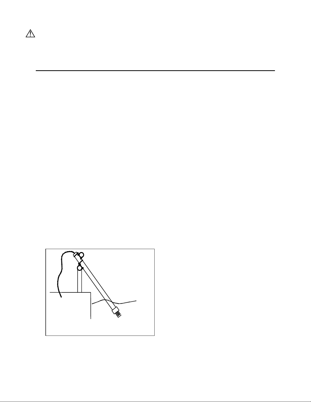
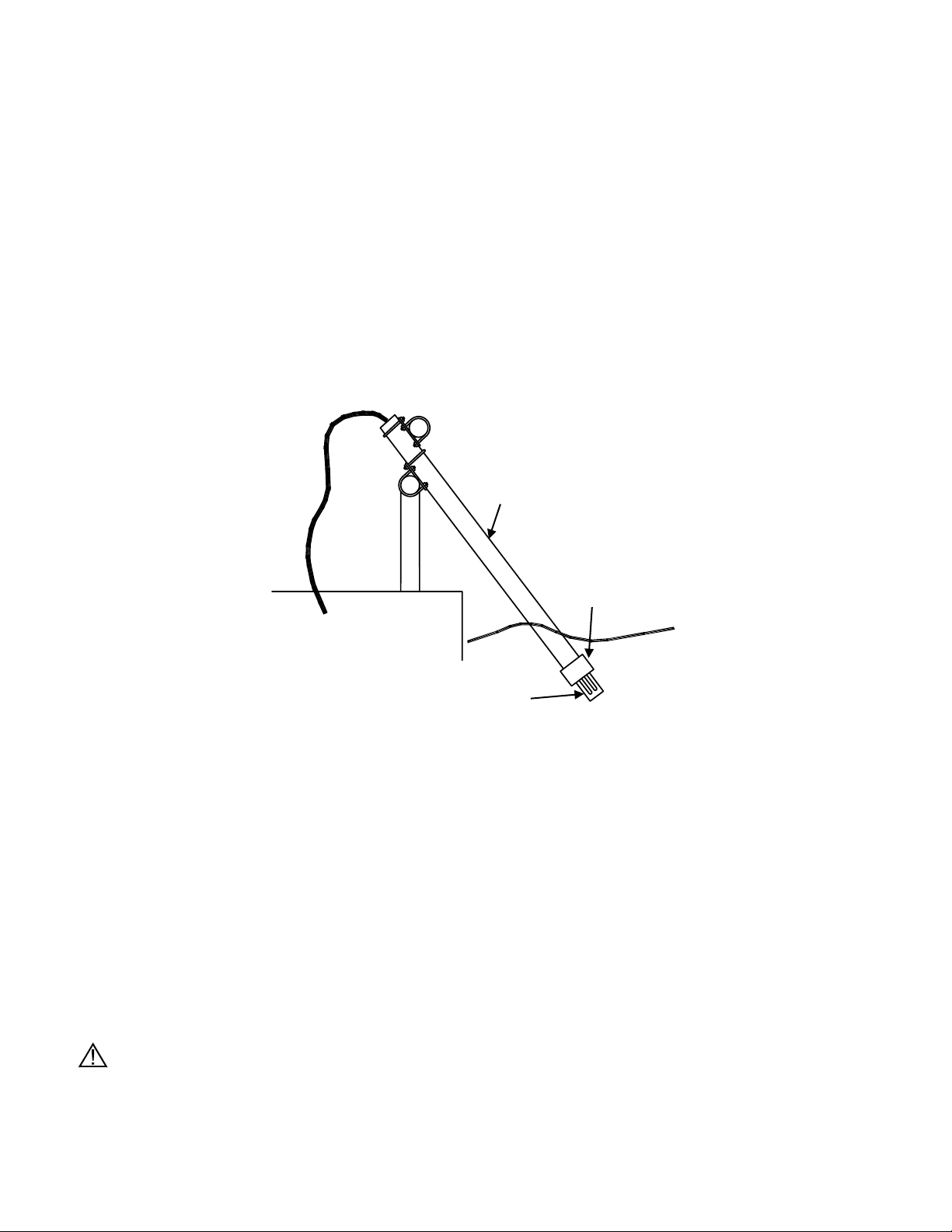
Ö Ideally, the probe should be placed at an angle within 45° of vertical and directed with the flow
direction (see Figure 3-1). This location will provide for the least stress on the support arm
holding the probe while minimizing the opportunity to collect debris. Placement against the flow
stream or perpendicular to the flow stream also provides accurate monitoring, but inspection and
cleaning may be required more frequently due to increased collection of debris.
Probe
to
scale.
drawn
Figure 3-1 Probe orientation (using rail mount kit)
The flow stream should be as free as possible of debris (e.g., algae) which could collect on the probe and
cause erroneous readings. See 3.5 Installing the 5562 or 5561 Probe Assemblies for flow requirements.
YSI Incorporated 10 5200 Recirculating System Monitor
Page 13
Note that this is an on-line device that is measuring actual conditions in real time. Composite sampling
N
for pH, for example, will not match on-line monitoring. Therefore, pH values recorded by the chart
recorder and/or plant control system connected to the 5200 Monitor cannot be averaged to equal the pH of
a composite sample.
3.2.2 Choosing a Monitor Location
The probe measures conditions in the flow stream and transmits a low voltage signal to the 5200 Monitor.
The probe is attached to a cable that is equipped with a “military grade” watertight connection to the
monitor.
Several options are available for mounting the 5200 Monitor. Easy to use, wall mount brackets (006515
Flange Mounting Kit) are provided with the 5200. If rail or panel mounting is desired, the 6509 Rail
Mount Kit and 6510 Panel Mount Kits are available as accessories.
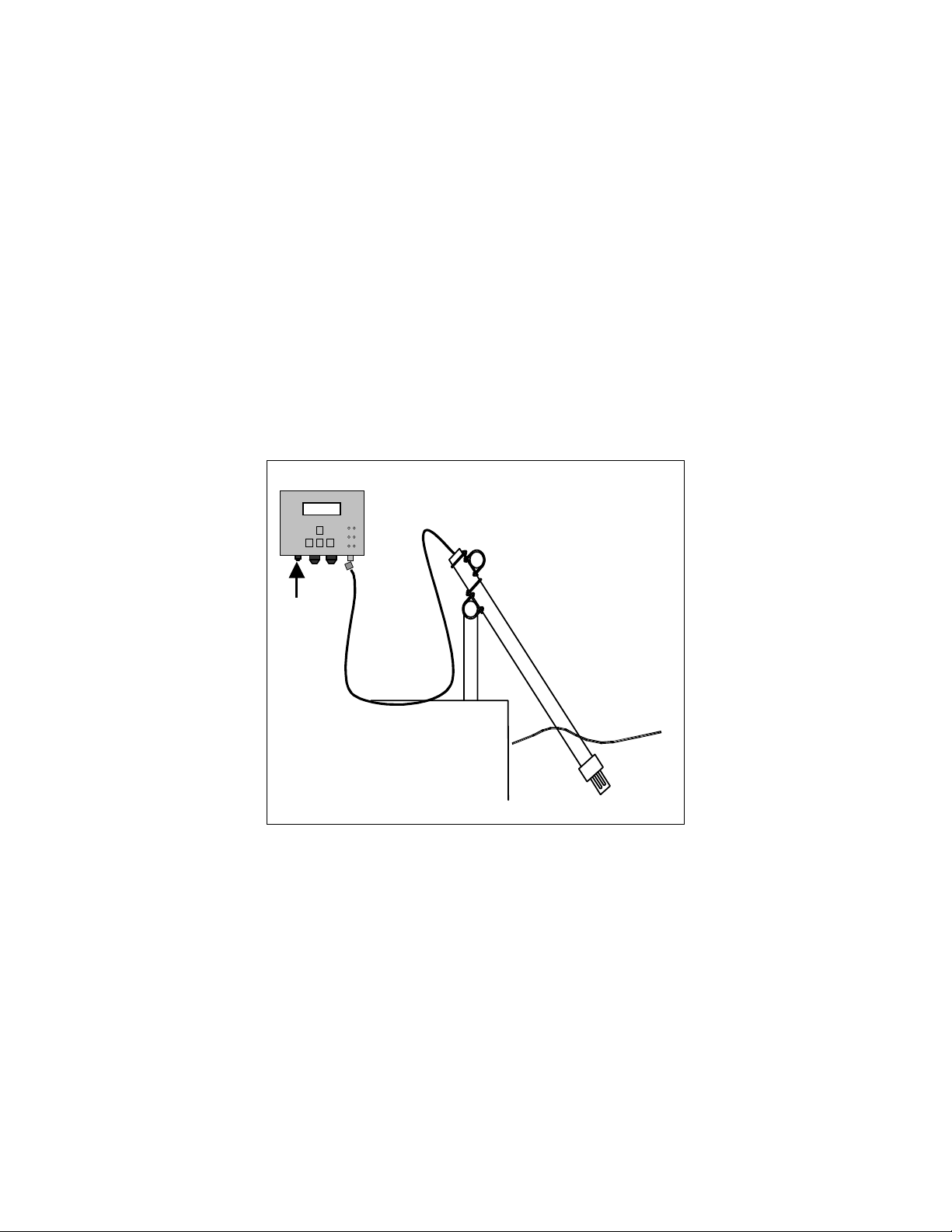
NOTE: The 5200 Monitor is provided with a weatherproof enclosure that will withstand most
environmental conditions with no compromise to system performance. An optional Weather
Shield (YSI #6505) is available for added protection from the elements. When mounting the 5200
outdoors the 6505 Weather Shield should be used.
5200 Monitor
5200
Recirculating
DO 5.30 Mg/L
System
02/02/00 9:30PM
Monitor
ESC
↵
DC
Probe
ot drawn to scale.
Stream
Figure 3-2 Monitor and probe installed using 6511 probe rail mount kit
Locating the monitor close to the sample location has advantages since accuracy checks and calibration
can be more easily facilitated under this arrangement. For example, a recently calibrated, hand-held
dissolved oxygen meter can be placed next to the 5200’s probe and readings can be compared.
Probe cables for the 5200 Monitor are available in 4 (13.1 ft), 10 (32.8 ft) and 20 (65.6 ft) meter lengths.
The probe cable length determines the maximum distance the monitor can be mounted from the sample
being measured.
Location of the 5200 Monitor should be elevated and in a dry place above the potential flood level. The
unit should be easily accessible for an operator or technician.
Although the monitor is suitable for outdoor use, it should be located in an area where temperature
extremes, vibrations, electromagnetic and radio frequency interference are minimal. Select an installation
location that is at least two (2) feet from any high voltage conduit. Avoid mounting on severely vibrating
YSI Incorporated 11 5200 Recirculating System Monitor
Page 14

structures or near a high heat source, AC motor or transformer, radio transmitter or antenna. Be sure the
monitor can be fully opened and serviced at its installed location by maintenance personnel.
3.3 Installing the Components
There are three basic parts to installing the YSI 5200 Monitor, which are covered in the following
sections:
Ö Installing the YSI 5200 Monitor hardware and additional components
Ö Installing the probe assembly
Ö Wiring the 5200 Monitor
3.3.1 Sealants, Desiccants and Securing the Monitor
Since the 5200 Monitor will likely be subjected to environmental conditions that promote formation of
condensation, it is very important to follow the instructions below before securing the cover to your
unit(s). This will prevent damage to the electronic components within the Monitor and extend the life of
the monitoring system.
The 5200 Monitor is shipped with three compression fittings. The small compression fitting on the left
side of the bottom panel is to be used for the power supply wire. The two larger compression fitting are
supplied with solid plugs installed. These solid plugs should be left in place if no other electrical
connections are to be made to the 5200.
If electrical connections are required for control relays, PC connections or other devices, there are a
number of options to ensure a watertight installation to the 5200’s case.
1. Solid plugs, located in the 2 larger compression fitting, can be frozen (put in a freezer for 1 hour) and
then easily drilled to the required diameter. The drill bit diameter should be slightly smaller than the
wire diameter so that a watertight seal can be made.
2. Compression plugs with two different pre-sized holes are supplied with the 5200 Monitor. The hole
size in the plugs varies with the amount of torque applied to the compression nut. To install a predrilled plug, the solid plug can be “pushed out” of the compression fitting housing and the pre-drilled
plug installed.
3. Optional conduit fittings (YSI #065926) can be installed in place of the compression fittings. When
using conduit fittings, industrial encapsulant (YSI #065921 conduit sealer) must be used to prevent
moisture from entering the 5200 monitor. After all wiring and connections are complete, apply the
sealant to the conduit openings from the inside of the 5200 Monitor. Failure to use industrial
encapsulant may result in damage to the 5200 Monitor.
Also included with the 5200 Monitor is a desiccant pack, YSI #6506. Desiccant absorbs moisture
captured within the enclosure. After all wiring and connections are complete (just before the cover is to be
installed), place the desiccant pack inside the 5200 enclosure near the bottom right corner. Remove the
desiccant from its protective packet prior to installation.
Secure the monitor’s cover using four mounting screws. Note that the cover contains a captured rubber
gasket that provides weatherproofing. Make certain that the gasket is in place and not twisted or damaged.
Make certain that the large blue ribbon cable is not trapped in the gasket channel before inserting the
screws. When securing the screws, take care not to cross thread. The screws are stainless steel, and the
receiving threads are brass. Do not over-tighten!
CAUTION: Anytime the 5200 cover is removed, replace the desiccant pack with a new pack. Anytime
the 5200 front panel is removed, place it on top of the 5200 Monitor or secure it so that the blue ribbon
cable does not bear the weight of the cover.
YSI Incorporated 12 5200 Recirculating System Monitor
Page 15

3.3.2 Installation Check List
9 Determine optimum mounting location for the probe based on the parameters being measured and/or
controlled
9 Determine optimum mounting location for 5200 Monitor
9 Fabricate probe mounting plate if necessary
9 Mount the probe
9 Connect the probe to the monitor
9 Make wiring connections for relays
9 Make wiring connections for communication ports
9 Make wiring connections for DC power
9 Make ground wiring connections
9 Verify that all wiring connections are secure
9 Apply industrial encapsulant to conduit fittings-if applicable
9 Insert desiccant pack(s) into 5200 Monitor
9 Reinstall front cover to 5200
9 Recheck grounding and surge protection installations
9 Allow probe circuitry and sensors to warm up for several minutes
9 Calibrate the probes and program the monitor’s software
9 Place calibrated probe in mounting fixture
3.4 Mount the YSI 5200 Recirculating System Monitor
Several options are available for mounting the 5200 Monitor. Easy to use, wall mount brackets (6515
Flange Mounting Kit) are provided. If rail or panel mounting is desired, the 6509 Rail Mount Kit and
6510 Panel Mount Kits are available as accessories.
3.4.1 Wall Mounting Option
Although the monitor is designed for outdoor deployment, some operators may prefer the convenience of
reading the monitor under shelter, for example, inside a nearby building. Figure 3-4 shows this indoor
type of installation. Wall-mounting the 5200 Monitor is a simple process using the enclosed 006515
mounting hardware.
YSI Incorporated 13 5200 Recirculating System Monitor
Page 16
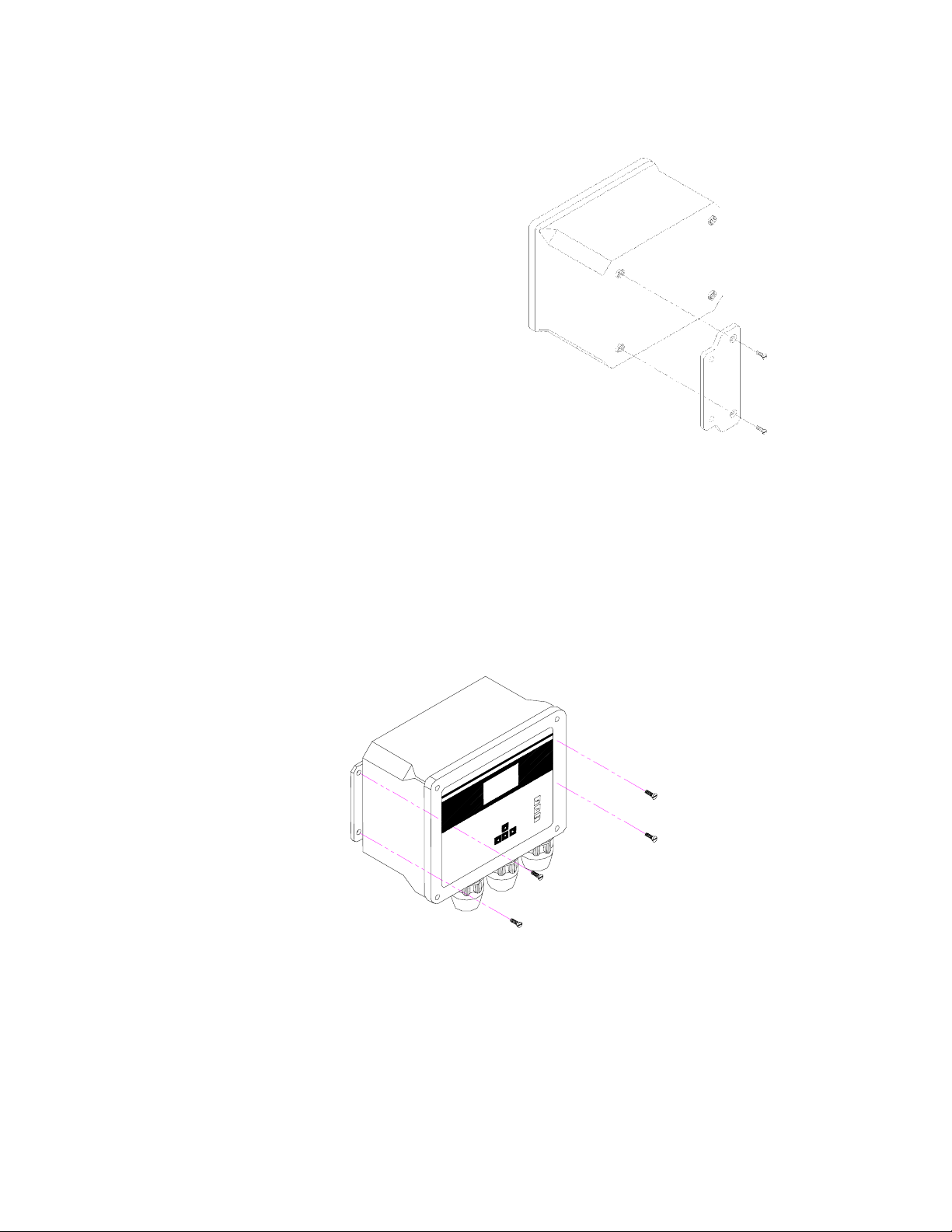
The following steps should be followed when wall
mounting the 5200 Monitor.
1. Loosely fasten the mounting brackets
(included) to the back of the 5200
Monitor with the mounting screws
provided as shown in Figure 3-3.
2. Tighten the screws, securing the brackets
to the Monitor.
3. Loosely fasten the 5200 Monitor to the
mounting surface with the mounting
screws provided as shown in Figure 3-4.
4. Tighten the screws, securing the Monitor
to the surface.
Figure 3-3 Attaching the Mounting Brackets
Figure 3-4 Securing the screws to the mounting surface
YSI Incorporated 14 5200 Recirculating System Monitor
Page 17
3.4.2 Optional 6509 – Rail Mount Kit
The 5200 Monitor can be easily mounted to pipe or handrail (1 to 1½ inch diameter) using the optional
6509 Rail Mount Kit. When using the 6509 Rail Mount Kit, the 006515 mounting flanges will have to be
modified by drilling two holes to accept the u-bolts. The predrilled metal plates can be used as a template.
CAUTION: The monitor should not be mounted on electrical conduit, a hot or vibrating pipe or structure,
or near a high heat source, an AC motor, transformer, radio transmitter or antenna.
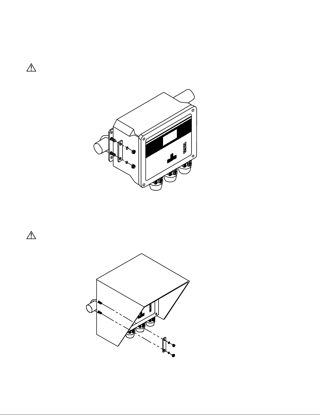
3.4.3 Optional 6505 – Weather shield
The Weather Shield provides wall or optional rail mounting capability for the 5200 Monitor.
CAUTION: The monitor should not be mounted on electrical conduit, a hot or vibrating pipe or structure,
or near a high heat source, an AC motor, transformer, radio transmitter or antenna.
YSI Incorporated 15 5200 Recirculating System Monitor
Page 18
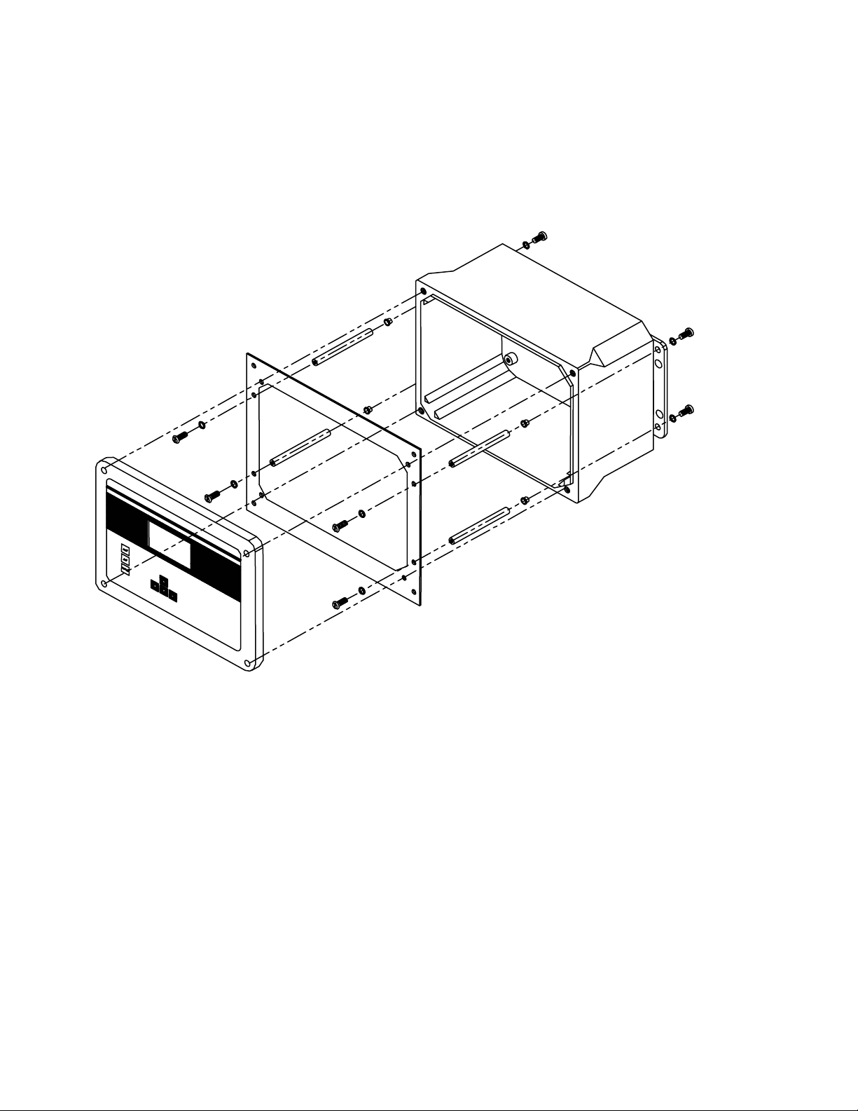
3.4.4 Optional 6510 – Panel Mount Kit
Panel mounting the 5200 Monitor is a simple process using the 6510 Panel Mount hardware and the
following tools; 5/32” Allen wrench, Philips screwdriver, and the necessary tools for cutting the mounting
hole in the control panel. The 5200 Monitor may be mounted in any panel with 9.5”L x 7.5”W space
available, and behind the panel depth of 5.5”.
YSI Incorporated 16 5200 Recirculating System Monitor
Page 19

3.5 Installing the 5562 or 5561 Probe Assemblies
CAUTION: Keep pH and ORP probe tips IN A MOIST ENVIRONMENT at all times.
After you have chosen suitable sites for the monitor and probe, proceed with the probe installation as
described below.
Avoid routing probe cabling near wiring associated with rotating machinery and/or equipment involving
electrical switching or regulation. In all cases, it is desirable to locate the probes away from sources of
electrical interference such as UV sterilizers, florescent lighting, ballasts, pumps, etc. Consider placing
probe cabling in grounded metallic conduit if unstable readings appear due to electromagnetic
interference.
The 5200 can be configured with either a 5562 multiprobe assembly (DO, Conductivity, Temperature,
and optional pH or pH/ORP sensors) or a 5561 DO/Temp probe assembly.
NOTES: When the 5200’s control functions are to be used, probe placement will be critical to the
operation of the system. Consequently, a professional should be consulted when designing the
system.
Water flow is important to the operation of the DO sensor. In addition, the mixing action provided
by water flow ensures that the area of sampled water is representative of the entire body of water.
Probe installation steps:
1. Select a suitable location for the probe assembly that allows for adequate water flow across the
DO sensor (approximately 0.5 ft/sec).
2. Select a method of securing the probe assembly.
3. Determine a method of routing and securing the cable.
In-Filter Location— A common place for probe location is in the filter. Installing probes in a filter or
sump requires that the probe be secured or hung in an area that will allow for adequate water flow across
the DO sensor (approximately .5 ft/sec).
In-Filter Location Using a Float—A float installation keeps probes at a constant depth, and is
economical to purchase or construct.
To construct a probe float, cut a hole (slightly smaller than the probe diameter) through a small piece of
Styrofoam. Insert the probe into the float so that the entire sensor guard protrudes through the Styrofoam
and the sensors are completely submerged.
In-Tank Location—Installing the probe assembly in a tank requires that the assembly be secured or
hung in an area that will allow for adequate water flow across the DO sensor (approximately 0.5 ft/sec). It
is preferred that the probe be secured so that the cable is not constantly flexed.
If using the 5562, the probe assembly can be secured using the 5205 Probe Mounting Kit or 6511 Probe
Rail Mount Kit. See Section 3.5.2 5205 and 6511 – Optional Probe Mount Kits for 5562 Probes. A
mounting kit is not available for the 5561 probe.
In-Line Location Using a Tee-Fitting—Although in-line probe placement is more time consuming and
requires some extra plumbing, it has been found to be a very effective and safe way to place probes. Inline placement gives accurate readings because water is moving across the probe tips at all times. It also
minimizes biological growth on the sensors.
IMPORTANT NOTE: When maintenance and/or calibration of the sensors is required, the probe
assembly will have to be removed from the in-line fitting. Take this into account when designing the
system. If water flow must be maintained during maintenance, by-pass plumbing will be required.
YSI Incorporated 17 5200 Recirculating System Monitor
Page 20
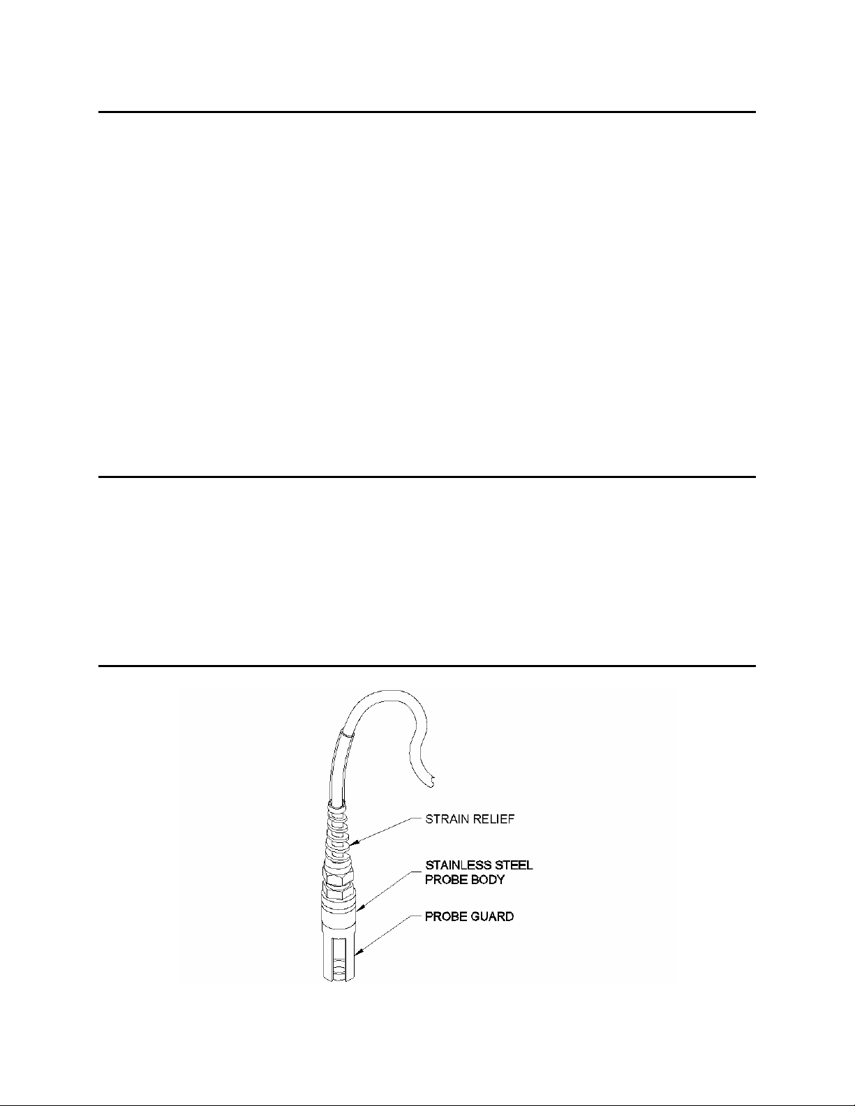
For this type of installation, the probe guard is removed and the probe is threaded into a tee-fitting using
the probe guard’s threads. All probes need to be placed into the flow stream. YSI does not provide tee
fittings for this type of installation.
Thread size for 5562 multiparameter probe assembly: 1.50-12 UNF 2A
Thread size for 5561 DO/Temp probe assembly: ¾-27 Class 2 thread
In–Line Location Using A Flow Cell (5562 Probe only) – The 5083 Flow Cell can be connected
anywhere in the pumping system where a water flow rate of 2–3 L/minute can be obtained. Maximum
pressure rating for the 5083 is 25 psi. A portion of water from a pump discharge line can be diverted
through the 5083 Flow Cell, or a method with a designated pump can be utilized.
3.5.2 5205 and 6511 – Optional Probe Mount Kits for 5562 Probes
NOTE: The 6511 kit includes Clamps for Rail Mounting. The 5205 Kit does not include mounting
hardware.
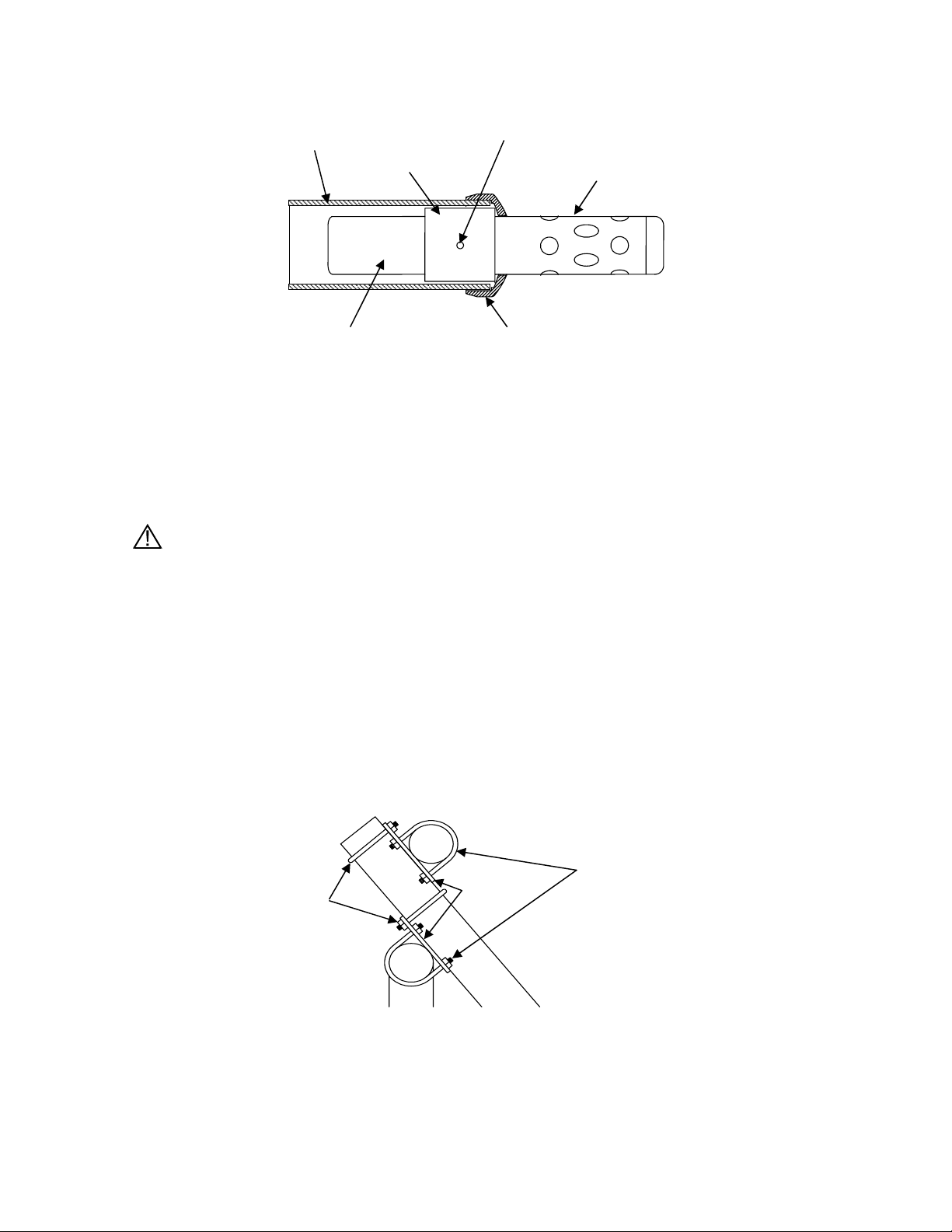
2” Schedule
40 PVC
Stop
Probe
Guard
Figure 3-5 Probe Mounting Kit
5205 and 6511 Probe Mount Kits allow a 5562 Probe to be deployed in a permanently mounted two-inch
schedule 40 PVC tube. The schedule 40 PVC is not included in the kit. Once installed, the probe is
deployed by gently sliding it down the tube, where it will rest on a stop cap at the end of the tube. The
sensors and probe guard will protrude through a hole in the stop cap at the end of the tube. See Figure 3-5.
When mounting to a 1–1½″ railing, the 6511 kit should be used. It includes brackets and u-bolts for rail
mounting and a stop cap and adaptor. See Figure 3-5.
When mounting to structures other than 1–1½″ railing, a 5205 kit should be used. When using the 5205
kit, the installer must develop a method of mounting the 2″ PVC tube to a permanent structure. The 5205
kit consists of a stop cap and adapter and does not include mounting hardware.
The 5205 and 6511 Kits should not be mounted on hot or vibrating pipes or structures, or near high heat
sources, AC motors or transformers, radio transmitters or antennas.
CAUTION: Do not mount on electrical conduit.
YSI Incorporated 18 5200 Recirculating System Monitor
Page 21
2” PVC Tube
Adapter
Set Screw
Probe Guard
5562 Probe Body
Stop Cap
Figure 3-6 Adapter Position
The following steps should be followed when mounting the 5205 or 6511 Probe Mount Kit.
1. With the 3 setscrews removed from the adapter, slide the adapter over the 5562 Probe. Align the
open screw holes directly over the 3 hex bolts located on the side of the 5562 Probe.
2. Insert the setscrews so that they seat into the head of the probe’s hex bolts.
CAUTION: Do not over-tighten the setscrews or damage to the probe body or adapter may
occur.
NOTE: The 5562 Probe Assembly can be deployed without the probe guard attached. When doing so,
application related precautions must be considered or system performance can be compromised.
Deployment without the guard is preferred as the effects of low water flow and fouling are
reduced, but exposed sensors or the DO membrane, can be damaged if not properly protected.
3. Attach the stop cap to the end of a PVC pipe using PVC cement, as per instructions on the cement
can label, ensuring that the stop cap is positioned straight and the pipe is fully inserted.
4. 5205 Only: Firmly mount PVC pipe to permanent structure. Skip to Step 9.
5. Loosely fasten two 1½” u-bolts on each mounting plate to the railing, orientated as shown in
Figure 3-7.
1.5” U-Bolts
2” U-Bolts
Mounting
Plates
Figure 3-7 6511 U-Bolt Mounting
6. Loosely attach the 2” u-bolts to the mounting plates, orientated as shown in Figure 3-7.
YSI Incorporated 19 5200 Recirculating System Monitor
Page 22
7. Slide the uncapped end of the PVC pipe up through the 2” u-bolts until there is approximately 1”
of the PVC pipe above the upper mounting plate, and tighten 2” u-bolts. Note: Do not over
tighten u-bolts or deformation of the PVC pipe may occur.
8. Tighten all remaining u-bolts to secure pipe.
9. Slowly slide the 5562 Probe/Adapter Assembly down the PVC pipe until it rests on the Stop Cap.
10. Connect the cable to the 5200 Monitor.
3.6 Wiring the System
WARNING: All wiring involving connections to mains power must be performed by a qualified licensed
electrician, and must conform to all locally applicable electrical codes. Any mains power circuit
connected within the YSI 5200 enclosure must be protected by a Ground Fault Circuit Interrupt device.
Do not make connections while power is applied. Disconnect power before proceeding.
WARNING: The 5200 utilizes sensitive solid-state devices that can be damaged by static shock.
Installers must observe accepted ESD (Electro-Static Discharge) procedures while connecting cabling to
the 5200 I/O plate or damage may result.
The 5200 Monitor has one MS-19 connector and three compression fittings in the bottom of the monitor
housing. The two larger compression fittings can be replaced with ¾ inch conduit fittings. From a front
view, the smaller compression fitting on the left is for 12-volt power. The opening on the right is for
communications and I/O wiring and the center opening is for relay wiring.
NOTE: The 5200 Monitor is supplied with components necessary to make reliable electrical connections.
When received, pluggable sockets are installed in the power, relay, RS485 and auxiliary ports.
These sockets are to be unplugged prior to making electrical connections and reinstalled after
connections are made.
CAUTION: It is essential that all sensor wiring be run in a separate cable or conduit from power wiring.
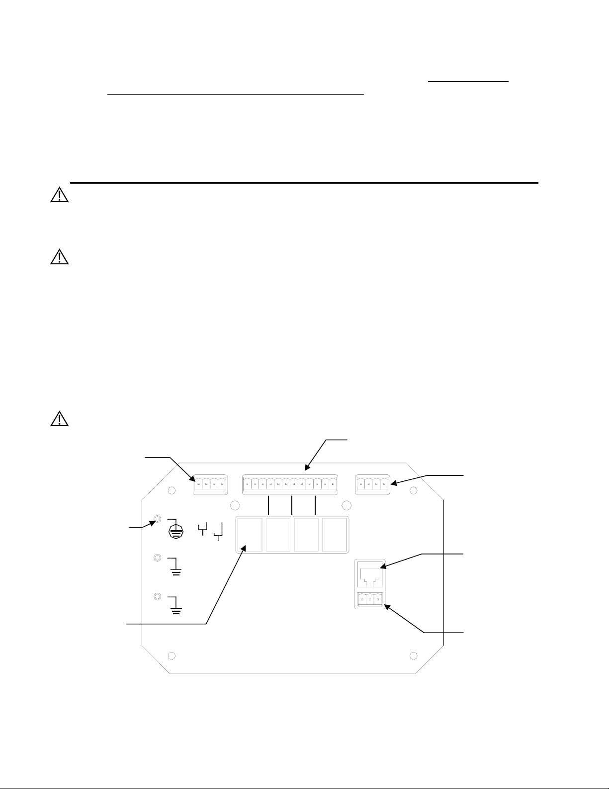
Relay Outputs
12VDC Primary
and Back-up
Power
Connector
Connect to
POWER IN
12V, 1A MAX
COM (-)--
MAIN (+)--
BACKUP (+)--
RELAYS
123
4
NETWORK
RS485 5200
Network Connector
R(-)--
N.C.--
N.C.--
N.C.--
N.O.--
N.O.--
COM--
COM (-)--
COM--
N.C.--
N.O.--
COM--
COM--
T(-)--
N.O.--
R(+)--
T(+)--
earth ground
RS232 and
Control Relays
(4) soldered to
PCB
YSI MODEL 5579
FOR LOAD CONNECTIONS USE
WIRE SUITABLE FOR 90°C
REQUIRED, 1A MAX
12V BATTERY FUSE
IN 1 --
IN 2 --
GND--
SERIAL IP
PORT
TCP/IP Serial
Connector
(RJ-45)
Aux. Analog and
Digital Input
Connector
Figure 3-8 I/O Plate
YSI Incorporated 20 5200 Recirculating System Monitor
Page 23
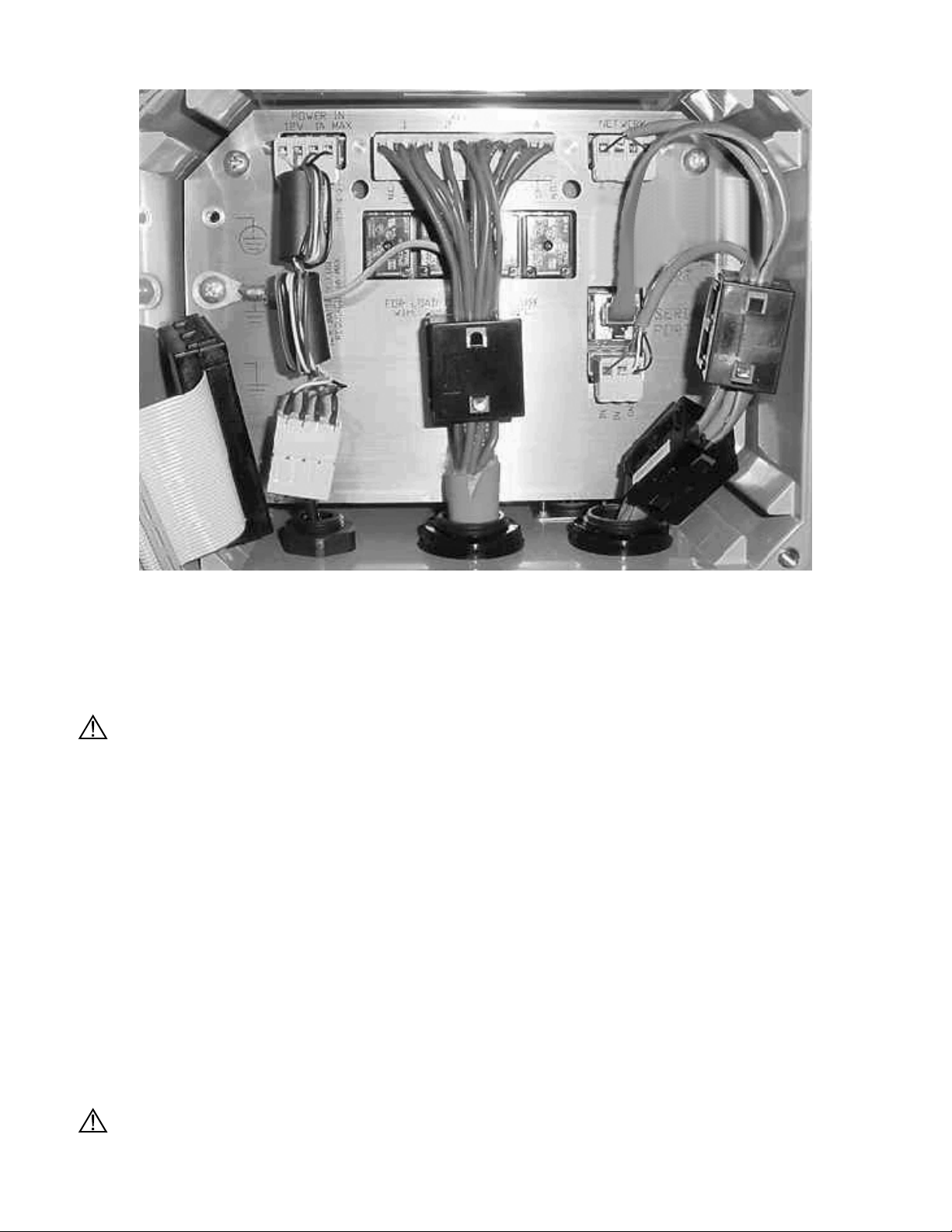
Figure 3-9 Placement of Ferrites and Pluggable Sockets
3.6.1 DC Power Input Wiring
12VDC power for the 5200 Monitor may be supplied by the YSI 5578/5579 power supply accessory
provided with the unit, or by a 12VDC source supplied by the user.
CAUTION: The YSI 5578/5579 power supply accessory is for indoor use only, and must be connected to
the 5200 Monitor with a suitable waterproof extension cable if the 5200 Monitor is installed in a damp
location.
For outdoor or damp locations, the YSI 5578/5579 power supply may also be installed in a NEMA 4X
enclosure adjacent to the 5200.
3.6.2 Installing the 5578/5579 Power Supply
When using the 5579 power supply it should be wired as follows: (see Figure 3-9)
• Connect the Inline Power Ferrite Assembly, YSI# 655385, to the I/O plate power connector. Failure
to do so could cause catastrophic monitor failure.
• Route the 5578/5579 power supply wire through the small compression fitting and into the case.
• Connect the 5578/5579 wires to the 4-pole 605223UL Pluggable Socket Connector so that the white
wire goes to Main (+) and black wire to Common (-).
• Connect the 4-pole 605223UL Pluggable Socket Connector to Inline Power Ferrite Assembly.
• Tighten compression fitting. See Section 3.3.1 Sealants, Desiccants and Securing the Monitor.
WARNING: A UL Listed DC power supply is required for any installation which is connected to “mains
YSI Incorporated 21 5200 Recirculating System Monitor
Page 24

supply” or other power source which is “hazardous live” per UL 3101-1 Section 3.5.2.
The 5200 Monitor may be powered by any regulated 8.5–16.5 VDC source that can provide
approximately 800mA of current and is isolated from mains supply by double or reinforced insulation.
(An unregulated supply may also be acceptable if the peak output voltage does not exceed 16.5VDC.)
WARNING: A UL Listed slow-blow fuse with a maximum current rating of 1A must be connected in
series with the positive terminal of any power supply not provided by YSI.
CAUTION: Power supply voltage above 16.5VDC may permanently damage the 5200 Monitor.
When the front panel of the 5200 Monitor is removed, take care not to drop the cover since it is not
hinged to the Monitor.
CAUTION: The sensitivity and stability of the monitor will be impaired if the monitor is not grounded.
Do not apply power to the Monitor until all electrical connections are verified and secure. Connect earth
ground to the 5200 I/O plate (see Figure 3-8 I/O Plate).
3.6.3 Back-up Power
WARNING: A UL Listed slow-blow fuse with a maximum current rating of 1A must be connected in
series with the positive terminal of the back-up supply.
The 5200 Monitor will automatically switch to auxiliary battery back-up operation if primary voltage
drops below 8.5 VDC, providing back-up power is connected. For proper back-up power operation, use
the YSI 5578/5579 Power Supply as the primary power source. Use of a different primary power supply
may prevent proper switching to back-up power.
WARNING: A UL Listed DC power supply is required for any installation which is connected to “mains
supply” or other power source which is “hazardous live” per UL 3101-1 Section 3.5.2.
The auxiliary power source is user supplied and can come from a variety of choices including lead acid or
gel cell external batteries. The 5200 will not charge batteries, so quality assurance maintenance
procedures must be established if batteries are used as the back-up power source.
Input power requirements for back-up operation are the same as primary power, 8.5–16.5 VDC at
approximately 800mA. With no primary power, when the back-up voltage falls below 7.0 volts the 5200
will cease to operate properly.
Connecting back-up power to the 5200 Monitor
Refer to Figure 3-9.
• If necessary, disconnect power to the 5200 Monitor
• Route the back-up supply wire through the compression fitting and into the case. See Section 3.3.1
Sealants, Desiccants and Securing the Monitor.
• Connect the back-up wires to the 4-pole 605223UL Pluggable Socket Connector so that the positive
wire goes to the Back-up (+) terminal and the negative wire goes to the Common (-) terminal.
• Connect the 4-pole 605223UL Pluggable Socket Connector to Inline Power Ferrite Assembly. Failure
to do so could cause catastrophic monitor failure.
• Connect the Inline Power Ferrite Assembly to the I/O plate power connector.
IMPORTANT: After completing system installation, test back-up power by removing main power while
all control/alarm relays are energized. At cold temperatures, logged data may be lost due
to temporary power loss when switching to battery backup power.
YSI Incorporated 22 5200 Recirculating System Monitor
Page 25
CAUTION: The sensitivity and stability of the monitor will be impaired if the monitor is not grounded.
Do not apply power to the Monitor until all electrical connections are verified and secure.
3.7 Communications Method
The 5200 has three methods of communication:
Ö RS232 TCP/IP Serial Port—to directly connect with a computer or network
Ö Modem—to communicate with a computer or pager via phone line
Ö RS485 Network—to directly connect with other 5200s
3.7.1 RS232 and TCP/IP Port
RS232 serial and TCP/IP communications are made through the TCP/IP port. This port can be
permanently connected to a PC or network for continuous monitoring applications, or to the 5201 Modem
sending alarm messages via phone. The RS232/TCP/IP port uses a standard RJ-45 connector.
Two snap on ferrite assemblies, YSI# 655361, are included with the 5200 Monitor. Wires being
connected to the communication port need to be routed through the ferrites as shown in Figure 3-9.
Failure to do so could cause catastrophic monitor failure.
RS232 PC Connection
When connecting the 5200 via the serial port to a PC for continuous operation, use an inline RS232 OptoIsolator device (YSI# 5285 or equivalent) to prevent ground loops. Failure to use this device may cause
incorrect DO, pH, ORP and conductivity data to be displayed and logged. Mount the isolator as close to
the PC as possible or in an area where it is protected from moisture.
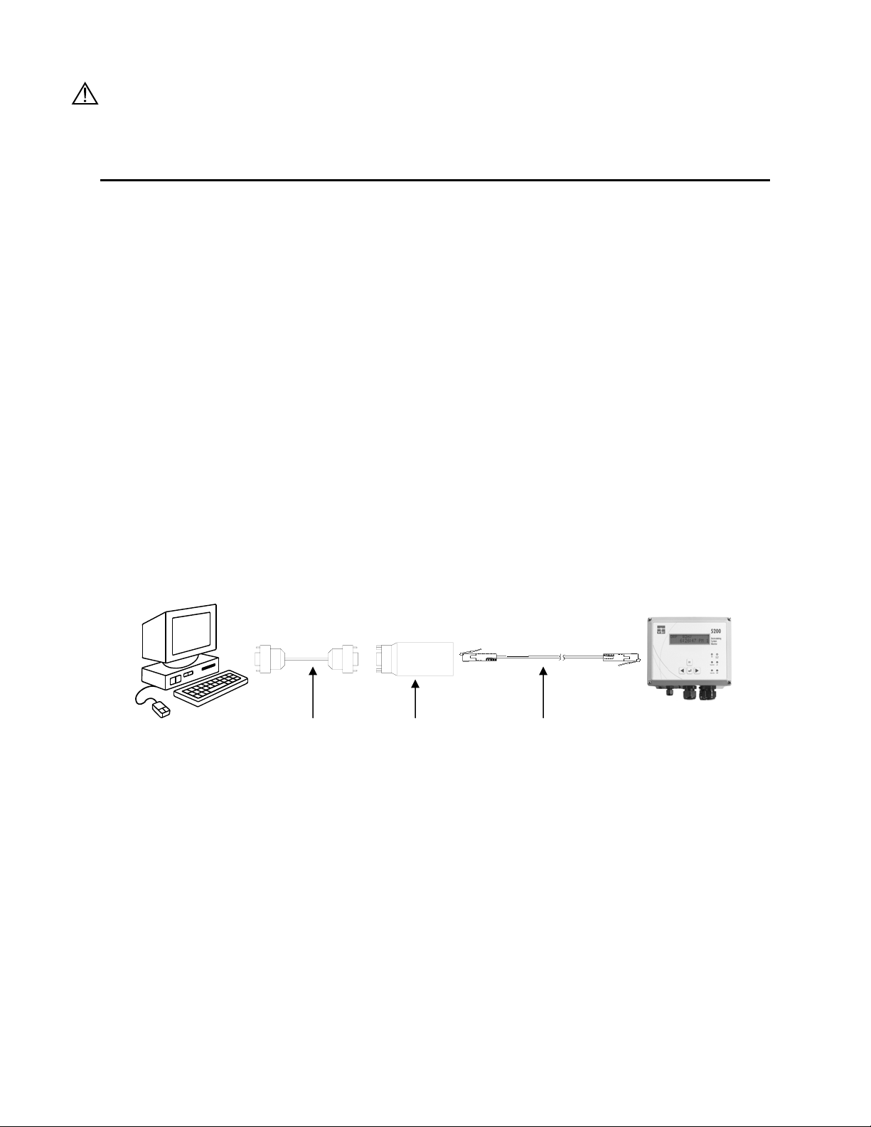
Computer DB9 RS232
Serial Cable
YSI 5285
Opto-Isolator
RJ-45 Straight-through
Cat 5 network cable
5200 Monitor
RS232 Serial Connection to a PC
When making RS232 cable runs greater than 100 feet (30.5 meters), use an RS232 Line
Extender/Booster. Not using this device may cause communication failures. Mount the booster in an area
where it is protected from moisture.
When temporarily connecting the 5200 to a PC, a “Straight-Pinned” Dual Male RJ-45 cable and a DB-9
to RJ-45 Adapter (YSI# 655383) wired as in the chart below are required.
YSI Incorporated 23 5200 Recirculating System Monitor
Page 26
Wiring Diagram for DB-9 to RJ-45 Adapter
Wire color internal to
Signal name (from 5200) RJ-45 pin #
adapter (may change
DB-9 pin #
based on supplier)
TX (232TXD) 4 Red 3
RX (232RXD) 5 Green 2
Common (DGND) 6 Yellow 5
CTS (232CTS) 7 Brown 8
DTR (232DTR) 8 Gray 4
Supplied with the 5200 are a YSI# 655384 Straight-pinned Cat 5 EIA568 compliant network patch cable
and pre-wired YSI# 655383 RJ-45 to DB-9 Adapter. The supplied cable and adapter are only intended to
be used for software upgrades or downloading data. Do not use this cable for long-term installation as the
compression fitting cannot form a proper seal. See Section 3.3.1 Sealants, Desiccants and Securing the
Monitor.
Bulk cable for permanent installations must be round (to allow the compression fitting to seal) and should
be purchased locally. A crimping tool will be required to install RJ-45 connectors to each end of the
cable.
IMPORTANT: 1. The connector that is to connect inside the case should be crimped after the cable is
run through the compression fitting.
2. Round cable must be used so a watertight seal at the compression can be achieved.
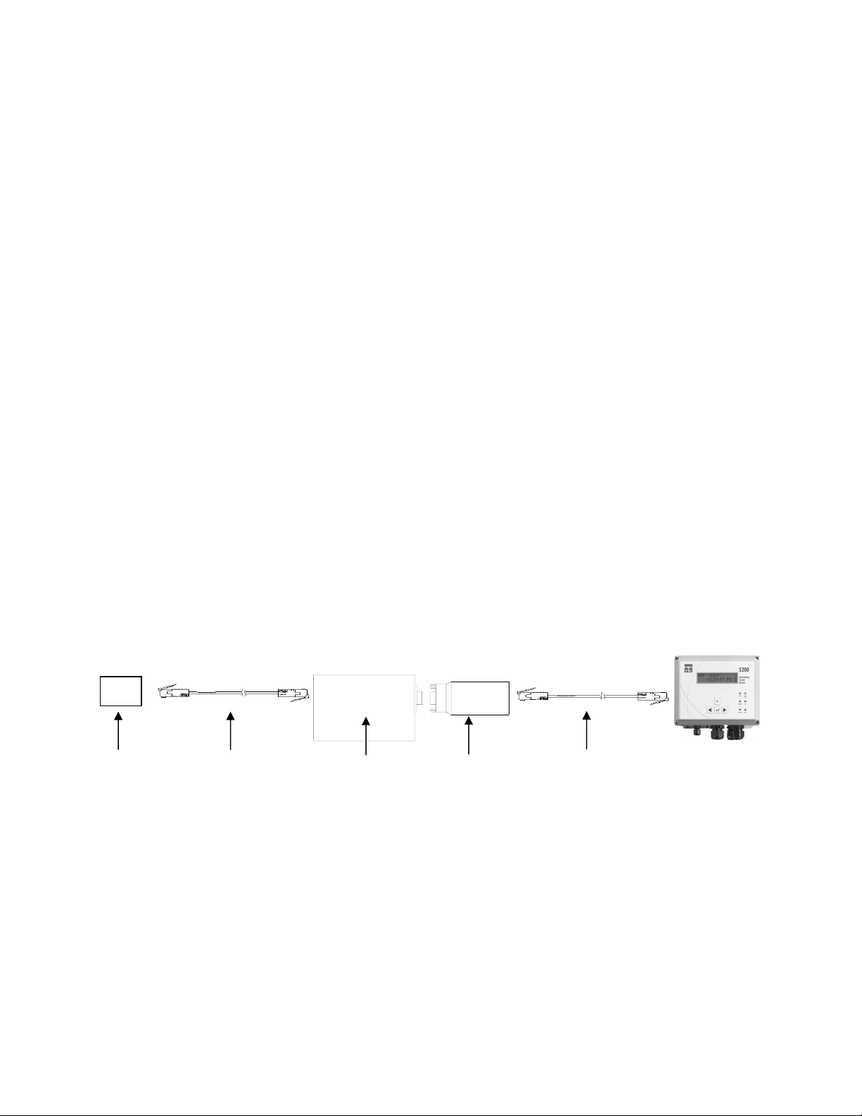
TCP/IP LAN Connection
An Ethernet serial server is required to connect the 5200 to a LAN. The serial server must be assigned a
static IP address.
LAN
Ethernet
network
RJ-45 Straight-through
Cat 5 network cable
Ethernet Serial
Server
DB9 to RJ-45
adapter
RJ-45 Straight-through
Cat 5 network cable
5200 Monitor
TCP/IP Connection to a LAN
Additional RS232 TCP/IP Wiring Information
The 5200 uses a symmetrical EIA-232 data terminal equipment (DTE) pinout on the RJ-45 serial port.
Table 3-1 lists the pinouts of the RJ-45 ports used for EIA-232 serial communications.
YSI Incorporated 24 5200 Recirculating System Monitor
Page 27

RJ-45 Pin
Number
1 DCD I NC P Signals module that remote device is
2 RTS O NC P Flow control, to enable remote device to
3 SG
4 TXD O P P Serial data out, from YSI-5200 to remote
5 RXD I P P Serial data in, from remote device to YSI-
6 SG
7 CTS I NC P Flow control, to enable YSI-5200 to send
8 DTR O NC P Signals remote device that YSI-5200 is
RS232
Name
Direction RS232 TCP/IP Signal Function
attached and powered on
send data
P P Signal return (NOT chassis ground)
device
5200
P P Signal return (NOT chassis ground)
data on TXD
attached and powered on
Table 3-1
To connect the 5200 to an EIA-232 device, it needs to be determined if the device connector wiring
follows the standard for data terminal equipment (DTE) or for data communication equipment (DCE). In
general, modems are wired as DCE devices and all other devices are wired as DTE; however, some
equipment manufacturers may deviate from the standard. In most cases, you use "straight through" RJ-45
cable. If you use "crossover" RJ-45 cable, the RJ-45 pins will be reversed.
3.7.2 5201 Modem
The YSI 5201 Modem is available only for use within the United States. For modem support outside the
US, an external modem registered for use within the local country is required. See Section 17
International Modem Support.
The YSI 5201 Modem mounts inside the 5200 case and connects to the RS232/TCP/IP Port. Refer to the
5201 Modem Installation Instructions, included with the modem, for details.
CAUTION: The phone line entering the 5200 case must be #26 AWG wire and must be sealed where it
enters the case or the instrument may be seriously damaged.
CAUTION: The ground wire from the 5201 Modem must be connected to the ground screw on the 5200
I/O plate.
3.7.3 RS485 Network
Connecting 5200s via the RS485 network is described in 8.1 RS485 Network.
YSI Incorporated 25 5200 Recirculating System Monitor
Page 28

3.8 Grounding Information
This section contains important installation information regarding grounding of the 5200 Monitor.
Connect earth ground to the 5200 I/O panel as described below in 3.9 Safety ISSUES.
The probe is powered by the 5200 Monitor and will be operated with a “floating” ground reference. This
requires that the probe not be individually grounded. Grounding the probe individually will cause a
“ground loop”; i.e. one conductor of the probe output grounded common to both the probe and the
monitor. Grounding the probe will cause significant performance problems with the sensors and likely
result in erroneous readings.
CAUTION: Do not ground the probe body.
All tanks should be electrically grounded via a ground probe.
3.9 Safety Issues
The electrical system must be grounded via the I/O plate to avoid possible electrical shock or damage to
the equipment (see Figure 3-8 I/O Plate).
WARNING: Turn off all power and assure power “lockout” before servicing to avoid contact with
electrically powered circuits.
To avoid possible electrical shock, do not touch other circuit components when making adjustments to the
5200 Monitor circuit board. Disconnect external power to the unit before connecting or disconnecting
wiring.
3.10 Lightning and Surge Protection
Surge protectors are strongly recommended to protect from secondary surges and lightning on outdoor
installations.
Surge suppression devices should be located on the AC line supplying power to the 5200 Monitor and any
signal lines connecting the 5200 Monitor.
AC line voltage surge suppressors protect field equipment on any AC line to ground from damage due to
electrical transients induced in the interconnecting power lines from lightning discharges and other high
voltage surges. The unit should include noise filtering, common mode and normal mode suppression and
nanosecond reaction time. Surge suppressors should be internally fused to remove the load if the unit is
overloaded or the internal protection fails.
Signal line suppressors protect low voltage signals and relay outputs from damage due to electrical
transients induced in the signal lines from lightning discharges or nearby electrical devices. Signal line
suppressors should be installed at each end of an analog loop. Relay outputs should be protected at the
receiver end. Signal line suppressors should consist of a three-element gas tube followed by metal oxide
varistors and suppressor diodes. The protective elements should be matched such that high-energy surge
voltages trigger the gas surge arrester, while low energy or surge voltages affect the MOV’s and
suppressor diodes.
Lightning protection devices should be located as close to the monitor as possible and wired in
accordance with the National Electric Code in approved watertight enclosures.
CAUTION: This or any other installation procedure cannot protect against a direct lightning strike. YSI
Incorporated cannot accept liability for damage due to lightning or secondary surges.
YSI Incorporated 26 5200 Recirculating System Monitor
Page 29
Section 4. Probe Module
Probe Module covers the following:
Ö Unpacking the Probe Module Ö Features of the YSI 5561 Probe Module Ö Features of the YSI 5562 Probe Module Ö Preparing the YSI 5561 Probe Module Ö Preparing the YSI 5562 Probe Module Ö Membrane Cap Installation Ö Calibration/Storage Cup (5562 only) Ö Instrument/Cable Connection
Two different probe modules are available for the YSI 5200 Recirculating Monitor. The YSI 5561 Probe
module is used for measuring dissolved oxygen and temperature only, while the YSI 5562 Probe module
is used for measuring dissolved oxygen, temperature, conductivity, and optional pH or pH/ORP. A 4, 10
or 20 meter cable is directly connected to the probe module body making it waterproof.
4.1 Unpacking the Probe Module
1. Remove the Probe module from the shipping box(es).
NOTE: Do not discard any parts or supplies.
2. Use the packing list to ensure all items are present.
3. Visually inspect all components for damage.
NOTE: If any parts are missing or damaged, contact your YSI Service Center immediately. Refer
to Section 14 WARRANTY AND SERVICE INFORMATION or www.ysi.com/environmental.
4.2 Features of the YSI 5561 Probe Module
Figure 4-1 5561 Probe Module
YSI Incorporated 27 5200 Recirculating System Monitor
Page 30
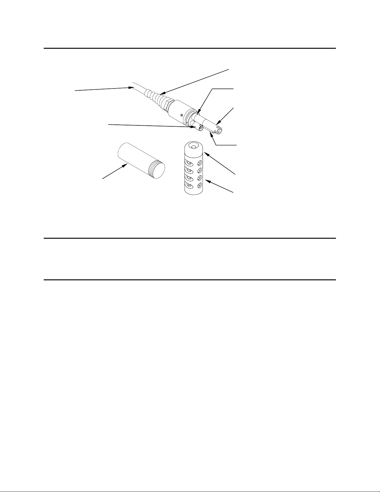
4.3 Features of the YSI 5562 Probe Module
Cable
Dissolved Oxygen
(DO) Probe
Calibration/
Storage Cup
Figure 4-2 5562 Probe Module
Strain Relief
Metal Probe
Connector Nut
pH/ORP Probe
Conductivity/Temperature
Probe
Detachable Weight
Probe Sensor Guard
4.4 Preparing the YSI 5561 Probe Module
To prepare the YSI 5561 Probe Module for calibration and operation, you need to install a new DO
membrane cap. Refer to Section 4.6 Membrane Cap Installation for details.
4.5 Preparing the YSI 5562 Probe Module
To prepare the YSI 5562 Probe Module for calibration and operation, you need to install the sensors into
the connectors on the probe module bulkhead. In addition to sensor installation, you need to install a new
DO membrane cap.
4.5.1 Sensor Installation
Whenever you install, remove or replace a sensor, it is extremely important that the entire probe module
and all sensors be thoroughly dried prior to the removal of a sensor or a sensor port plug. This will
prevent water from entering the port. Once you remove a sensor or plug, examine the connector inside the
probe module sensor port. If any moisture is present, use compressed air to completely dry the connector.
If the connector is corroded, return the probe module to your dealer or directly to YSI Customer Service.
Refer to Section 14 Warranty and Service Information.
Conductivity/Temperature and pH, pH/ORP Sensor Installation
1. Unscrew and remove the probe sensor guard.
2. Using the sensor installation tool supplied in the YSI 5511 maintenance kit, unscrew and remove
the sensor port plugs.
YSI Incorporated 28 5200 Recirculating System Monitor
Page 31

port
Figure 4-3 Port Plug Removal
3. Locate the port with the connector that corresponds to the sensor that is to be installed. The
number of pins is specific for each probe type.
pH or pH/ORP port
Oxygen port
Conductivity/Temperature
Figure 4-4 Sensor Port Identification
4. Apply a thin coat of o-ring lubricant (supplied in the YSI 5511 maintenance kit) to the o-rings on
the connector side of the sensor (see Figure 4-5 O-Ring Lubrication).
O-Rings
Sensor nut
Figure 4-5 O-Ring Lubrication
CAUTION: Make sure that there are NO contaminants between the O-ring and the sensor.
Contaminants that are present under the O-ring may cause the O-ring to leak.
5. Be sure the probe module sensor port is free of moisture and then insert the sensor into the correct
port. Gently rotate the sensor until the two connectors align.
6. With connectors aligned, screw down the sensor nut by hand, and then tighten using the sensor
installation tool.
Figure 4-6 Sensor Inst a llation
YSI Incorporated 29 5200 Recirculating System Monitor
Page 32

CAUTION: Do not cross thread the sensor nut. Tighten the nut until it is flush with the face of
the probe module bulkhead. Do not over tighten.
Figure 4-7 Bulkhead Seating
7. Repeat steps 3-6 for any other sensors.
8. Replace the probe sensor guard.
Dissolved Oxygen Sensor Installation
The YSI 5562 comes with the DO sensor already installed. Refer to Section 11.4.2 DO Sensor
Replacement for instructions on installing the YSI 558 Replaceable DO Module Kit.
4.6 Membrane Cap Installation
NOTE: The DO sensor was shipped dry. A shipping membrane cap was installed to protect the electrode.
A new membrane cap must be installed before the first use.
1. Unscrew and remove the probe sensor guard.
2. Unscrew, remove, and discard the old membrane cap.
3. Thoroughly rinse the sensor tip with distilled water.
4. Install a gasket from the 5204 Teflon or 5909 PE Membrane Kit onto the DO sensor.
Membrane Cap
Gasket
DO Sensor
Probe Body
Figure 4-8 Gasket Installation
Gasket Installed
5. Seat the gasket all the way down against the probe body. A small pair of tweezers may aid in the
installation.
6. Prepare the electrolyte according to the directions on the electrolyte solution bottle.
7. Hold the new membrane cap and fill it at least 1/2 full with the electrolyte solution.
YSI Incorporated 30 5200 Recirculating System Monitor
Page 33

CAUTION: Do not touch the membrane surface.
8. Screw the membrane cap onto the sensor moderately tight. A small amount of electrolyte should
overflow.
9. IMPORTANT: To prevent the formation of a bulge in the membrane (which can slow sensor
response), partially unscrew the membrane cap then retighten.
10. Screw the probe sensor guard on moderately tight.
4.7 Calibration/Storage Cup (5562 only)
The YSI 5562 Probe module is supplied with a convenient calibration/storage cup. This cup is an ideal
container for calibration of the different sensors, minimizing the amount of solution needed. Refer to
Section 6 Calibration.
4.7.1 Calibration/Storage Cup Installation
1. Remove probe sensor guard, if already installed.
2. Ensure that an o-ring is installed in the o-ring groove on the threaded end of the probe module
body.
3. Screw the calibration/storage cup on the threaded end of the probe module and securely tighten.
NOTE: Do not over tighten as this could cause damage to the threaded portions.
Figure 4-9 Calibration/Storage Cup Installation
O-ring
4.8 Instrument/Cable Connection
Attach the probe cable to the instrument as follows:
1. Line up the pins and guides on the cable with the holes and indentations on the cable connector at
the bottom of the YSI 5200 instrument.
YSI Incorporated 31 5200 Recirculating System Monitor
Page 34

r
Figure 4-10 Bottom Connectors
2. Holding the cable firmly against the cable connector, turn the locking mechanism clockwise until
it snaps into place.
3. Remove the cable from the instrument by turning the cable connector counterclockwise until the
cable disengages from the instrument.
Probe
Connecto
YSI Incorporated 32 5200 Recirculating System Monitor
Page 35
Section 5. Operation
p
ppt
Operation covers the basic set up and operation of the 5200 Recirculating Monitor including:
Ö Run Screen Ö Main Menu Ö Parameters Menu Ö Daily Checks Ö System Test
See Section 9 Advanced Setup for more advanced set up options.
In the Parameters menu section, Temperature is explained in step-by-step detail as an example. Once
familiar with the temperature set up procedure, other parameters can be set up in a similar manner.
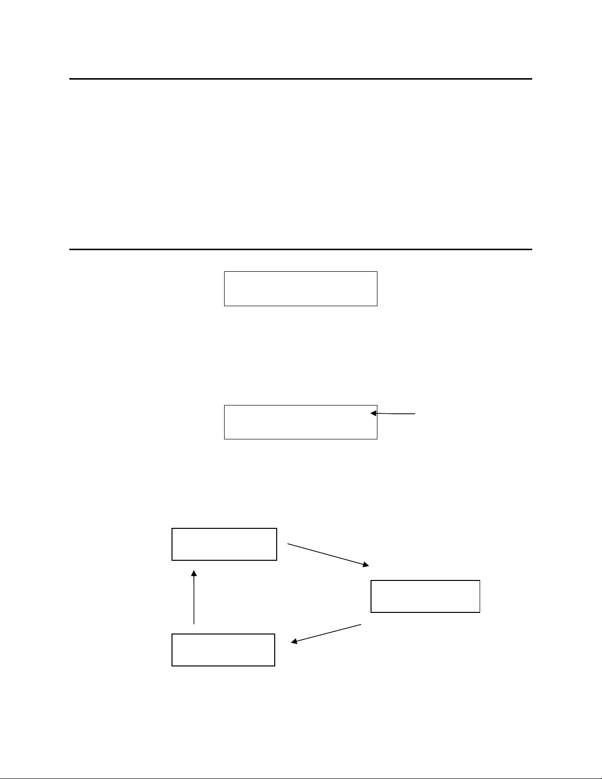
5.1 Run Screen
The initial 5200 display is the Run screen.
DO 8.31 mg/L
Temp 18.5 °C
The current values of enabled parameters are displayed (two at a time in a rotating fashion) on the Run
Screen. The speed with which the display automatically rotates through these values can be changed (see
Section 9.1.4 Display, Display Speed). The parameters may also be manually rotated by pressing the [e]
or [f] arrow key. Press the [
display. An H will appear to the right of the parameter indicating Hold mode. Press the [
hold the 2
through all parameters.
nd
displayed parameter. Press the [ESC] key again to return to the normal display that rotates
ESC] key to hold the currently shown parameter on the top line of the
ESC] key again to
DO 7.15 mg/L H
Hold indicator
Temp 18.5 °C
Any messages will also appear on the Run Screen. As systems are activated or alarms are triggered the
display provides up to date status on the system being managed. Up to 16 events are saved and displayed
in sequence. Figure 3.2 shows the Run screen.
DO 7.11 mg/L
Tem
18.5°C
Current readings and any
messages rotate through the
display. (Order may vary)
pH 7.32
ORP 270 mV
Cond. 24.0ms*
Sal. 10.4
YSI Incorporated 33 5200 Recirculating System Monitor
Page 36

Cond 24.0mS *
Sal. 10.4ppt
The status LEDs show the current status of each parameter as follows:
OFF – parameter not enabled
GREEN – normal range
FLASHING GREEN – control mode (turns off when it crosses the original set point)
RED – alarm (turned off by pressing any key, except escape, and resolving the alarm condition)
Indicates temperature
compensation
5.2 Main Menu
Run Screen
Serv ic e HoldSystem Menu Parameter Menu Timer Menu
Figure 5-1 Main Menu
From the Run screen, press the Enter [
] key to enter the Main menu.
Service Hold
Enter to Select
NOTE: Service Hold is the first selection in the Main menu. It allows you to perform service operations
(clean probes, provide tank maintenance etc.) without breaching any alarms or set points. See
Section 9.2.2 Service Hold.
Press the [e] or [f] key to rotate through the Main menu selections.
Parameters
Enter to Select
The menus are displayed in the order indicated in Figure 5-1, starting with Service Hold. You can cycle
through the menus as many times as you desire in either direction using the arrow keys.
NOTE: Entering the menus automatically turns off all 4 internal control relays.
YSI Incorporated 34 5200 Recirculating System Monitor
Page 37

5.3 Parameters Menu
The Parameters Menu allows you to enter the menu for specific measurement parameters. In addition to
establishing Set Points, Control Points and Alarms, the Parameters menu also enables the user to perform
calibrations (refer to Section 6 Calibration for calibration routines). The majority of the day-to-day
operations of the YSI 5200 will be accessed through this menu.
The options in this menu include:
Ö DO System
Ö pH System
Ö ORP System
Ö Temperature System
Ö Conductivity System
Ö Salinity System
Ö Auxiliary System
Param e ters Me nu
Salanity DO Menu ORP MenuCond Menu Temp MenupH MenuAUX Menu
Enable System
(Yes/N o)
Save Changes
Figure 5-2 Parameters Menu
5.3.1 Entering Setpoint and Range Values
Various Set Points and ranges must be established for each of the five monitoring parameters that are
enabled: conductivity, temperature, pH, ORP and DO.
Ö The optimal Set Point value.
Ö The control range, or High and Low Set Points.
Ö The alarm range.
YSI Incorporated 35 5200 Recirculating System Monitor
Page 38

Low
Alarm
ON
Low
Control
ON
Acceptable
Operating
Range
Hi
Control
ON
High
Alarm
ON
Low
Alarm
Setpoint
Low
Control
Setpoint
ON
Optimal
Setpoint
Value
High
Control
Setpoint
ON
High
Alarm
Setpoint
Figure 5-3 Setpoints and Ranges
When these values are entered, the system will operate as illustrated in Figure 5-3. As long as the water
quality parameters remain within the acceptable operating range, no control or alarm will be activated. If,
however, a parameter rises above or falls below the acceptable operating range, the YSI 5200 will activate
the appropriate control device. The control device remains in operation until the parameter returns to the
Set Point value.
As you enter a Set Point value, the YSI 5200 may prompt you if there are problems with the set up. If the
High or Low value breaches the optimal Set Point, you will see an Autofix question displayed that will
automatically adjust your High or Low value to a value ±0.1 or ±0.01 to the high or low side of your
optimal Set Point depending on the parameter of interest. For example, pH will be adjusted to the
hundredths place while DO will be adjusted to the tenths place.
If you had your optimal Set Point at 8.0 mg/L for DO and the Low range at 7.8 and the High range at 8.2
and you changed your optimal Set Point to 7.7 then attempted to escape without resetting the High and
Low ranges, you would see the following displayed:
Setpoint Errors.
Auto Fix? YES
If you choose YES, the Low range Set Point would automatically be adjusted to 7.6, but the High range
Set Point would remain 8.2 because it did not get breached.
IMPORTANT: For Controlling Applications, it is highly recommended that you use Alarms and verify
all Set Point, Alarm and Control Range settings.
This product has been designed and tested to provide trouble free service. However, as with all
microprocessor based products, there is potential for failure which could cause loss of control functions.
Proper QC procedures can reduce the potential for failure. See 11.3 Recommended Quality Assurance
Protocol.
The default set point and alarm values loaded during factory configuration are shown below.
YSI Incorporated 36 5200 Recirculating System Monitor
Page 39

Parameter Set Point High Set
ORP +400 mV +425 mV --- +375 mV --- +435 mV +300 mV
Temperature 25oC or 77oF 26oC or
pH 7.00 7.50 --- 6.50 --- 8.00 6.00
Specific Conductance
(range dependent;
0-200 us, 0-2000 us,
0-20 ms, 0-200 ms)
Dissolved Oxygen 8.3 mg/L 8.5 mg/L 8.7 mg/L 8.1 mg/L 7.9 mg/L 8.9 mg/L 7.7 mg/L
(0-200 us)
160.0 us
(0-2000 us)
1600 us
(0-20 ms)
16.00 ms
(0-200 ms)
160.0 ms
Point #1
o
78.8
F
(0-200 us)
180.0 us
(0-2000 us)
1800 us
(0-20 ms)
18.00 ms
(0-200 ms)
130.0 ms
High Set
Point #2
--- 24
--- (0-200 us)
Low Set
Point #1
o
C or
o
75.2
F
140.0 us
(0-2000 us)
1400 us
(0-20 ms)
14.00 ms
(0-200 ms)
140.0 ms
Low Set
Point #2
--- 26.5
--- (0-200 us)
High Alarm Low Alarm
o
C or
o
79.7
F
190.0 us
(0-2000 us)
1900 us
(0-20 ms)
19.00 ms
(0-200 ms)
190.0 ms
o
C or
23.5
o
74.3
F
(0-200 us)
130.0 us
(0-2000 us)
1300 us
(0-20 ms)
13.00 ms
(0-200 ms)
130.0 ms
5.3.2 Temperature System
Temperature is explained in step-by-step detail as an example. Once you are familiar with the temperature
set up procedure, other parameters can be set up in a similar manner.
From the Parameters menu, press the [e] or [f] key until the Temp System option appears.
Temp System
Enter to Select
Press the Enter [ ] key to enter the Temp System menu.
Temp System
ENABLED? Yes
If the Temperature System is disabled (as indicated by No appearing on the display), press the [e] or [f]
key to select Yes.
Temp System
ENABLED? Yes
Press the Enter [ ] key to confirm that the option is Enabled and enter the Temp System menu.
Set Point Menu
Enter to Select
Temperature System menu selections are shown below.
YSI Incorporated 37 5200 Recirculating System Monitor
Page 40

Temp Menu
Enabled
Yes
NO
Set Point
Range Low
Range High
Alarm Low
Alarm High
0-45 C
From 0.0 to 0.1
below Set Point
From Set Point +
0.1 to Max
From 0.0 to 0.1
below Range Low
From Range High
+ 0.1 to Max
Control MenuSet Point MenuSetup Menu
Range Low
Range High
Alarm Low
Alarm High
Alarm System
Select
Relay
Select
Relay
Select
Relay
Select
Relay
Enable System
F
C
Accept
Accept
(Yes/No)
Figure 5-4 Temperature Menu
Set Point Menu
From the Temp System menu, press the [e] or [f] key until the Set Point Menu option appears.
YSI Incorporated 38 5200 Recirculating System Monitor
Page 41

Set Point Menu
Enter to Select
Press the Enter [ ] key.
Enter to Select
SetPoint
Set Point Menu selections for Temperature are SetPoint, Range Low, Range High, Alarm Low and Alarm
High.
SetPoint
The Temperature Set Point defines the optimum Temperature that you wish the YSI 5200 to maintain in
the aquatic environment. This determines the control range for heating and chilling devices. See Section
5.3.1 Entering Setpoint and Range Values for an overview of control functions.
From the Set Point menu (with the SetPoint option displayed), press the Enter [
] key.
SetPoint
077.0°F
Using the [e], [f] and Enter [ ] keys, enter the Temp Set Point value.
NOTE: The previous value entered will be displayed.
SetPoint
069.0°F
Press the Enter [ ] key. The display returns to the Set Point Menu.
Enter to Select
SetPoint
Press the [f] key for the next Set Point selection, Range Low.
Range Low
From the Set Point menu (with the Range Low option displayed), press the Enter [ ] key.
Range Low
068.9°F
Using the [e], [f] and Enter [ ] keys, enter the Temperature Range Low value.
NOTE: The Range Low value must be lower than the Set Point.
Range Low
065.0°F
Press the Enter [ ] key. The display returns to the Set Point Menu.
Enter to Select
Range Low
Press the [f] key for the next Set Point selection, Range High.
YSI Incorporated 39 5200 Recirculating System Monitor
Page 42

Range High
From the Set Point menu (with the Range High option displayed), press the Enter [ ] key.
Range High
078.8°F
Using the [e], [f] and Enter [ ] keys, enter the Range High value.
NOTE: The Range High value must be higher than the Set Point.
Range High
074.0°F
Press the Enter [ ] key. The display returns to the Set Point Menu.
Enter to Select
Range High
Press the [f] key for the next Set Point selection, Alarm Low.
Alarm Low
From the Set Point menu (with the Alarm Low option displayed), press the Enter [ ] key.
Alarm Low
068.8°F
Using the [e], [f] and Enter [ ] keys, enter the Alarm Low value.
NOTE: The Alarm Low value must be lower than the Range Low.
Alarm Low
062.0°F
Press the Enter [ ] key. The display returns to the Set Point Menu.
Enter to Select
Alarm Low
Press the [f] key for the next Set Point selection, Alarm High.
Alarm High
From the Set Point menu (with the Alarm High option displayed), press the Enter [ ] key.
Alarm High
079.7°F
Using the [e], [f] and Enter [ ] keys, enter the Alarm High value.
NOTE: The Alarm High value must be higher than the Range High.
Alarm High
0 85.0°F
Press the Enter [ ] key. The display returns to the Temp System Menu.
YSI Incorporated 40 5200 Recirculating System Monitor
Page 43

Enter to Select
Alarm High
NOTE: You may enter the other Temperature System menu options (Control Menu, Alarms System and
Calibration), but your changes are not saved until you exit the Temp System menu as described
below.
Press the [ESC] key two times to exit the Temp System menu. You will be prompted to save your
changes.
Set Point Menu
Save? Yes
Press the Enter [ ] key to save the changes, or press the [e] or [f] key to select No, then press the
Enter [
Control Menu
After entering the Temperature set point and ranges, use the Control Menu to select which relay each
range or alarm will activate. At the beginning of the control range, the YSI 5200 will turn on the chiller or
heater, as required. These peripheral devices will remain activated to drive the temperature value back to
the optimal Set Point value, and once achieved, the peripheral device will be turned off. Since most
heaters and chillers have their own thermostat, these thermostats can be used as a backup temperature
control system. The heater thermostat should be set several degrees above your desired temperature and
the chiller several degrees below. If your desired temperature is 78°F then set your heater thermostat at
81°F and your chiller thermostat at 75°F.
] key to exit without saving any changes.
The YSI 5200 has a chiller hold off feature. When you are cooling (running a compressor using a relay)
the relay will turn on immediately but if cycled off and back on it will not allow the relay to come back on
for about 8 minutes. This keeps compressors from burning up.
From the Temp System menu, press the [e] or [f] key until the Control Menu option appears.
Control Menu
Enter to Select
Press the Enter [ ] key.
Enter to Select
Range Low
Control Menu selections for Temp are Range Low, Range High, Alarm Low and Alarm High.
Relay Setup
From the Control Menu, press the [e] or [f] key until the Range Low option appears.
Enter to Select
Range Low
Press the Enter [ ] key to select Range Low.
Range Low
Relay Disabled
YSI Incorporated 41 5200 Recirculating System Monitor
Page 44

Range Low menu selections are Relay Disabled, Relay Internal and Relay SubNet.
NOTE: Range High, Alarm Low and Alarm High menus have these same selections.
Relay Disabled
Relay Disabled is the default setting. It prevents the Range Low control point from triggering any relays
(Internal or SubNet). To select this option, press the [
ESC] key to return to the Control Menu.
Enter to Select
Range Low
NOTE: You may enter another of the other Control Menu options (Range High, Alarm Low and Alarm
High), but your changes are not saved until you exit the Control Menu as described below.
Press the [
ESC] key two times to exit the Control Menu. You will be prompted to save your changes.
Control Menu
Save? Yes
Press the Enter [ ] key to save the changes, or press the [e] or [f] key to select No, then press the
Enter [
Relay Internal
Set the Range Low control to trigger one of the four internal relays in this 5200 as follows:
From the Range Low menu, press the [e] or [f] key until the Relay Internal option appears.
] key to exit without saving any changes.
Range Low
Relay Internal
Press the Enter [ ] key to select Relay Internal.
Range Low
Relay R:1
Use the [e] or [f] key to select the desired Internal Relay number (1–4).
Range Low
Relay R:4
Press the Enter [ ] key.
NOTE: If the relay address is already in use, an error message will appear. See Section 13
Troubleshooting, Relay In Use Error Codes.
Enter to Select
Range Low
NOTE: You may enter another of the other Control Menu options (Range High, Alarm Low and Alarm
High), but your changes are not saved until you exit the Control Menu as described below.
Press the [
ESC] key two times to exit the Control Menu. You will be prompted to save your changes.
Control Menu
Save? Yes
YSI Incorporated 42 5200 Recirculating System Monitor
Page 45

Press the Enter [
Enter [
NOTE: Use the same procedure as described above to set up a relay to be triggered by Range High,
Relay SubNet
This function is for future expansion and is not yet available. Set the Range Low control to trigger an
external subnet relay (connected to this 5200 via the RS485 network).
] key to exit without saving any changes.
Alarm Low or Alarm High.
] key to save the changes, or press the [e] or [f] key to select No, then press the
Alarm System
The alarm system for each measurement parameter can be turned on or off. When on, an audible alarm
will sound on the YSI 5200 and an alarm page will be sent (if a modem is installed and paging is
enabled). The alarm will remain on until a key is pressed. See 7.1 Alarm Logic Flow Charts for details.
From the Temp System menu, press the [e] or [f] key until the Alarm System option appears.
Alarm System
Enter to Select
Press the Enter [ ] key.
Alarm System
Alarms? No
If the Temperature Alarm System is disabled (as indicated by No appearing on the display), press the [e]
or [f] key to select Yes.
Alarm System
Alarms? Yes
Press the Enter [ ] key. The display returns to the Temp System menu.
Alarm System
Enter to Select
NOTE: You may enter another of the Temp System menu options (Calibration, Set Point Menu or
Control Menu), but your changes are not saved until you exit the Temp System menu as
described below.
Press the [ESC] key to exit the Temp System Menu. You will be prompted to save your changes.
Alarm System
Save? Yes
Press the Enter [ ] key to save the changes, or press the [e] or [f] key to select No, then press the
Enter [
Setup Menu
The Setup Menu allows you to select the scale you wish to use for temperature measurement—Celsius or
Fahrenheit. The YSI 5200 controller is set to Celsius at the factory.
] key to exit without saving any changes.
YSI Incorporated 43 5200 Recirculating System Monitor
Page 46

Changing the temperature scale automatically recomputes your Set Points. For example, if your Set
Points were entered in Fahrenheit and you change the temperature scale to Celsius, all of your Set Points
will be automatically converted to their Celsius equivalents. Select the temperature scale as follows:
From the Temp System menu, press the [e] or [f] key until the Setup Menu option appears.
Setup Menu
Enter to Select
Press the Enter [ ] key.
Temp Scale
Enter to Select
Press the Enter [ ] key.
Temp Scale
Temp Scale? °C
Use the [e] or [f] key to select either °F or °C.
Temp Scale
Temp Scale? °F
Press the Enter [ ] key.
Temp Scale
Enter to Select
NOTE: You may enter another of the Temp System Menu options (Set Point Menu, Control Menu or
Alarm System), but your changes are not saved until you exit the Temp Setup Menu as described
below.
Press the [ESC] key two times to exit the Temp Setup Menu. You will be prompted to save your changes.
Setup Menu
Save? Yes
Press the Enter [ ] key to save the changes, or press the [e] or [f] key to select No, then press the
Enter [
] key to exit without saving any changes.
YSI Incorporated 44 5200 Recirculating System Monitor
Page 47

5.3.3 DO System
DO System menu selections are shown below.
DO Menu
NO
Setup Menu
Enabled
Yes
Set Point
Range 1 Low
Range 1 High
Set Point Value
From Min to .01
below Set Point
From Set Point +
.01 to Max
Gray menus only available with
Display Range set to Manual mode
and Interval set to Continuous.
Control MenuSet Point MenuCalibration
Range 1 Low
Range 1 High
Range 2 Low
Alarm System
Enable System
(Yes/No)
Select
Relay
Select
Relay
Select
Relay
Range 2 Low
Range 2 High
Alarm Low
Alarm High
From Min to .01
below Range 1 Low
From Range 1 High
+ .01 to Max
From Min to .01
below Range 2 Low
From Range 2 High
+ .01 to Max
Range 2 High
Alarm Low
Alarm High
Select
Relay
Select
Relay
Select
Relay
Figure 5-5 DO Menu
YSI Incorporated 45 5200 Recirculating System Monitor
Page 48

NOTE: Set Point, Control and Alarm System Menus are only available when a Manual Display Range is
selected (see Section 5.3.3 DO System, Setup Menu, Display Range) and the DO Interval is set to
Off (DO is on continuously). See Section 5.3.3 DO System, Setup Menu, Interval.
NOTE: DO readings are still compensated for salinity changes even if conductivity is disabled.
Calibration
Calibration is covered in Section 6 Calibration. DO can be calibrated in either % saturation
(recommended) or mg/L. See Section 6.2.2 Dissolved Oxygen Calibration for details.
Set Point Menu
Set Point Menu selections for DO are SetPoint, Range1 Low, Range1 High, Range2 Low, Range2 High,
Alarm Low and Alarm High.
SetPoint
The DO Set Point defines the optimum DO level that you wish the YSI 5200 to maintain in the aquatic
environment.
Low
Alarm
ON
Low
Alarm
Setpoint
Low
Control
ON
Low
Control
Setpoint
#2 ON
(DO only)
Control
Setpoint
Low
#1 ON
Acceptable
Operating
Range
Optimal
Setpoint
High
Control
Setpoint
#1 ON
Hi
Control
ON
High
Control
Setpoint
#2 ON
(DO Only)
High
Alarm
ON
High
Alarm
Setpoint
Figure 5-6 DO Setpoints
The DO system uses a more advanced control system employing two control ranges instead of just one as
in the other parameters (See Figure 5-6). The dual range design allows you to change the way oxygen
levels are managed in the system if the DO level moves out of the first range and into the second. This
provides the ability, for example, to use an air injection system (controlled by range 1) to maintain DO
levels for the first range and a pure oxygen injection system (controlled by range 2) as a backup should
the DO level continue to fall.
If the YSI 5200 senses that the DO level is outside of the operating Range #1 it will turn on the Range #1
control system. If the DO level continues to move outside of operating Range #2 then Range #2 control
system will activate.
NOTE: To allow for DO probe stabilization, the 5200 waits for two minutes after being powered up
before activating DO alarms or control.
Control Menu
After entering the DO set point and ranges, use the Control Menu to select which relay each range or
alarm will activate.
YSI Incorporated 46 5200 Recirculating System Monitor
Page 49

Alarm System
The alarm system for each measurement parameter can be turned on or off. When on, an audible alarm
will sound on the YSI 5200 and an alarm page will be sent (if a modem is installed and paging is
enabled). The alarm will remain on until a key is pressed. See 7.1 Alarm Logic Flow Charts for details.
Setup Menu
DO Setup Menu selections are shown below.
Setup
Interval
DIsplay Range
Display Format
Membrane Type
Off, 10, 20, 30, 40, 50, 60
Auto Accept
Manual
MG/L
%Sat
Low
High
Accept
Accept
PE
Teflon
Accept
Accept
Figure 5-7 DO Setup Menu
Interval
The 5200’s DO system operates in either continuous or interval mode. In continuous mode, the DO probe
is on all the time. In interval mode, the DO system is powered down for a selected interval (10, 20, 30, 40,
50 or 60 minutes), then powered back up for 75 seconds. The DO level is measured during the last 15
YSI Incorporated 47 5200 Recirculating System Monitor
Page 50

seconds of the powered cycle. The entire cycle is then repeated. Interval mode extends the time between
probe servicing and calibration, but disables DO control and alarm functions.
Display Range
The 5200’s DO system operates in either an Auto or Manual Range. Use Manual to enable the 5200’s
control and alarm functions. If you select Auto, the control/alarm options are NOT available.
CAUTION: Changing the display range will cause the DO alarm and control set points to change. After
changing the display range, confirm all set point values.
Display Format
The Display Format refers to the option between displaying your DO values in % saturation or mg/L.
Membrane Type
The 5200’s DO system can use either polyethylene or Teflon membrane caps. Teflon membranes offer
traditional, reliable performance for most applications; while polyethylene provide a significantly faster
response time and less flow dependence.
NOTE: After changing the membrane type, the DO probe must be calibrated. See 6.2.2 Dissolved
Oxygen Calibration.
YSI Incorporated 48 5200 Recirculating System Monitor
Page 51

5.3.4 pH System
pH System menu selections are shown below.
pH Menu
No
Enabled
Yes
Set Point
Range Low
Range High
Dose Up
Dose Up Wait
Dose Down
Dose Dpwn Wait XX MIN
Set Point Value
From Min to .01
below Set Point
From Set Point +
0.01 to Max
At Specific Value
for XX MIN
XX MIN
At Specific Value
for XX Sec
Control MenuSet Point MenuCalibration
Range Low
Range High
Alarm Low
Alarm High
Alarm System
Enable System
(Yes/No)
Select
Relay
Select
Relay
Select
Relay
Select
Relay
Alarm Low
Alarm High
From Min to 0.1
below Range Low
From Range High
+ .01 to Max
Figure 5-8 pH Menu
YSI Incorporated 49 5200 Recirculating System Monitor
Page 52

Calibration
Calibration is covered in Section 6 Calibration. pH can be calibrated at either one point or two points. See
Section 6.2.4 pH Calibration for details.
Set Point Menu
The YSI 5200 can control pH by dosing a buffer solution , injecting CO2 gas or both. pH control can
operate in two different ways. It can operate the same as most other 5200 control systems—when the
parameter value reaches the low or high range setpoint, control is activated until the value returns to the
optimal setpoint. Or, it can operate in a timed mode—when the value reaches the low or high range
setpoint, control is activated for a fixed length of time (Dose Time) regardless of whether or not the value
returns to the optimal set point. The 5200 then waits for a fixed length of time (Dose Wait) before
checking the value of the parameter and applying additional control. The default method of pH control is
the timed mode. To select the normal mode, set the Dose Time to 0.
When using timed mode, additional values must be entered on the Set Points Menu, including the dose
and dwell (Dose Wait) values. The dose time allows you to establish the length of time a dose is
administered and the dwell time allows for a period between doses to prevent over-applying a dose.
SetPoint
The pH Set Point defines the optimum pH level that you wish the YSI 5200 to maintain in the aquatic
environment. See Section 5.3.1 Entering Setpoint and Range Values for an overview of control functions.
Dose Up
Dose Up in minutes (time per dose of buffer solution) is the amount of time that the YSI 5200 will dose
buffer to bring the pH level back up into the target operating range to the optimal Set Point. The
acceptable values for buffer solution dosing are from 1 to 999 minutes. Set to 0 to select normal pH
control (see Section 5.3.4 pH System, Set Point Menu).
Dose Up Wait
Dose Up Wait (dwell time) is the length of time that the YSI 5200 will wait until dosing can occur again.
This feature prevents overdosing a system with buffer.
Dose Down
Dose Down (in seconds) controls how long the CO
range from 0 to 999 seconds. For example, if you enter 10 seconds, when the upper end of the target
operating range for pH is reached, the YSI 5200 will turn on the CO
to a lower value. A CO
Dose Down Wait time will force the YSI 5200 to wait to allow the gas to be
2
absorbed into the water. This will prevent the pH value from dropping too fast.
Set the Dose Down to 0 to select normal pH control (see Section 5.3.4, pH System, Set Point Menu) where
the YSI 5200 will turn the gas valve on when the pH level reaches the high end of the target operating
range and will keep the valve open until the pH drops below the optimal pH level. The 0 seconds option is
for systems with pressurized CO
injection.
2
WARNING: If the 5200 is instructed (by AquaManager) to transmit logged data during the Dose Down
cycle, dose time will be extended until data transmission is complete (up to 3½ minutes maximum with a
full data log).
gas valve will remain open. The possible values
2
gas for 10 seconds to reduce the pH
2
Dose Down Wait
Dose Down Wait time is the time that the YSI 5200 waits before allowing another CO2 gas injection to
occur. This time is selectable from 0-999 minutes. If the YSI 5200 senses that the pH is outside of the
YSI Incorporated 50 5200 Recirculating System Monitor
Page 53

target operating range, it will turn on the pH doser or CO
injector until the pH returns to the optimal Set
2
Point value.
Control Menu
After entering the pH set point and ranges, use the Control Menu to select which relay each range or
alarm will activate.
Alarm System
The alarm system for each measurement parameter can be turned on or off. When on, an audible alarm
will sound on the YSI 5200 and an alarm page will be sent (if a modem is installed and paging is
enabled). The alarm will remain on until a key is pressed. See 7.1 Alarm Logic Flow Charts for details.
YSI Incorporated 51 5200 Recirculating System Monitor
Page 54

5.3.5 ORP System
ORP System menu selections are shown below.
ORPMenu
No
Enabled
Yes
Display Actual Value " "
Current Temp Value
Scrolling Text*
Get UserValue
Calibration
Complete
Set Point
Range Low
Range High
Alarm Low
Alarm High
Set Point Value
From Min to .01
below Set Point
From Set Point +
.01 to Max
From Min to .01
below Range Low
From Range High
+ .01 to Max
Control MenuSet Point MenuCalibration
Range Low
Range High
Alarm Low
Alarm High
Alarm System
Enable System
(Yes/No)
Select
Relay
Select
Relay
Select
Relay
Select
Relay
Figure 5-9 ORP Menu
YSI Incorporated 52 5200 Recirculating System Monitor
Page 55

Calibration
Calibration is covered in Section 6 Calibration. See Section 6.2.5 ORP Calibration for details.
Set Point Menu
The ORP level can be used as an indicator of ozone. Acceptable levels are between 0 and 450 mV. The
ORP Set Point can be maintained through the use of an ozonizer in a monitoring and control system. The
Set Point can be established anywhere from –999 to +999 mV. For controlling applications you will also
need to establish the Low and High control values and alarm values.
SetPoint
The ORP Set Point defines the optimum ORP level that you wish the YSI 5200 to maintain in the aquatic
environment. See Section 5.3.1 Entering Setpoint and Range Values for an overview of control functions.
Control Menu
After entering the ORP set point and ranges, use the Control Menu to select which relay each range or
alarm will activate.
Alarm System
The alarm system for each measurement parameter can be turned on or off. When on, an audible alarm
will sound on the YSI 5200 and an alarm page will be sent (if a modem is installed and paging is
enabled). The alarm will remain on until a key is pressed. See 7.1 Alarm Logic Flow Charts for details.
YSI Incorporated 53 5200 Recirculating System Monitor
Page 56

5.3.6 Conductivity System
Conductivity System menu selections are shown below.
Conductivity Menu
No
Enabled
Setup Menu
Yes
Set Point
Range Low
Range High
Dose Up
Dose Up Wait
Set Point Value
From Min to .01
below Set Point
From Set Point +
0.01 to Max
At Specific Value
for XX Sec
XX MIN
Gray menus only available with
Display Range set to Manual mode.
Control MenuSet Point MenuCalibration
Range Low
Range High
Alarm Low
Alarm System
Enable System
(Yes/No)
Select
Relay
Select
Relay
Select
Relay
Dose Down
Dose Down Wait
Alarm Low
Alarm High
At Specific Value
for XX Sec
At Specific Value
for XX MIn
From Min to 0.1
below Range Low
From Range High
+ .01 to Max
Alarm High
Select
Relay
Figure 5-10 Conductivity Menu
YSI Incorporated 54 5200 Recirculating System Monitor
Page 57

NOTE: Set Point, Control and Alarm System Menus are only available when a Manual Display
Range is selected. See Section 5.3.6 Conductivity System, Setup Menu, Display Range.
Calibration
Calibration is covered in Section 6 Calibration. See Section 6.2.3 Conductivity Calibration for details.
Set Point Menu
Conductivity control, like pH, can operate in two different ways. It can operate the same as most other
5200 control systems—when the parameter value reaches the low or high range setpoint, control is
activated until the value returns to the optimal setpoint. Or, it can operate in a timed mode—when the
value reaches the low or high range setpoint, control is activated for a fixed length of time (Dose Time)
regardless of whether or not the value returns to the optimal set point. The 5200 then waits for a fixed
length of time (Dose Wait) before checking the value of the parameter and applying additional control.
The default method of Conductivity control is the timed mode. To select the normal mode, set the Dose
Time to 0.
When using timed mode, additional values must be entered on the Set Points Menu, including the dose
and dwell (Dose Wait) values. The dose time allows you to establish the length of time a dose is
administered and the dwell time allows for a period between doses to prevent over-applying a dose.
SetPoint
The Conductivity Set Point defines the optimum Conductivity level that you wish the YSI 5200 to
maintain in the aquatic environment. See Section 5.3.1 Entering Setpoint and Range Values for an
overview of control functions.
Dose Up
Dose Up in seconds (time per dose) is the amount of time that the YSI 5200 will dose to bring the
conductivity level back up into the target operating range to the optimal Set Point. The acceptable values
for dosing are from 1 to 999 seconds. A Dose Up Wait time forces the YSI 5200 to wait before applying
another dose. This will prevent the value from rising too fast. Set to 0 to select normal conductivity
control (see Section 5.3.6 Conductivity System, Set Point Menu).
WARNING: If the 5200 is instructed (by AquaManager) to transmit logged data during the Dose Up
cycle, dose time will be extended until data transmission is complete (up to 3½ minutes maximum with a
full data log).
Dose Up Wait
Dose Up Wait (in minutes), or dwell time, is the length of time that the YSI 5200 will wait until dosing
can occur again. This feature prevents overdosing a system with a dosing solution and protects against
“short cycling” of equipment.
Dose Down
Dose Down (in seconds) controls the length of time the 5200 will dose. The range is from 0 to 999
seconds. A Dose Down Wait time forces the YSI 5200 to wait before applying another dose. This will
prevent the value from dropping too fast.
WARNING: If the 5200 is instructed (by AquaManager) to transmit logged data during the Dose Down
cycle, dose time will be extended until data transmission is complete (up to 3½ minutes maximum with a
full data log).
YSI Incorporated 55 5200 Recirculating System Monitor
Page 58

Set the Dose Down to 0 to select normal conductivity control (see Section 5.3.6 Conductivity System, Set
Point Menu) where the YSI 5200 will start dosing when the conductivity level reaches the high end of the
target operating range and will keep dosing until it reaches the optimal set point.
Dose Down Wait
Dose Down Wait (in minutes), or dwell time, is the length of time that the YSI 5200 will wait until dosing
can occur again. This feature prevents overdosing a system with a dosing solution and protects against
“short cycling” of equipment.
Control Menu
After entering the Conductivity set point and ranges, use the Control Menu to select which relay each
range or alarm will activate.
Alarm System
The alarm system for each measurement parameter can be turned on or off. When on, an audible alarm
will sound on the YSI 5200 and an alarm page will be sent (if a modem is installed and paging is
enabled). The alarm will remain on until a key is pressed. See 7.1 Alarm Logic Flow Charts for details.
Setup Menu
Conductivity Setup Menu selections are Display Range and Temperature Compensation.
Setup
Display Range Temp. Comp.
Set Value (Default
Value 1.91)
0-200us
0-2000us
0-20ms
0-200ms
Auto
Figure 5-11 Conductivity Setup Menu
YSI Incorporated 56 5200 Recirculating System Monitor
Page 59

Display Range
The 5200’s Conductivity system operates in either Auto ranging or 1 of 4 manual ranges. Use a manual
range to enable the 5200’s control and alarm functions. If you select Auto, the control/alarm options
are NOT available.
CAUTION: Changing the display range will cause the Conductivity alarm and control set points to
change. After changing the display range, confirm all set point values.
Temperature Comp ensatio n
The conductivity of a sample varies with temperature, therefore, conductivity readings are normally
compensated to 25°C. An adjustment of approximately 1.91% per °C is common for the water
environment. The YSI 5200 has a default value of 1.91% and a range of 0–4%.
An asterisk next to the conductivity value on the 5200 display indicates that the reading is temperature
compensated. If the temperature compensation value is set to 0%, temperature compensation is disabled
and no asterisk is displayed.
5.3.7 Salinity System
The only Salinity Menu option is Enable/Disable.
5.4 Daily Checks
The YSI 5200 is designed to run 24 hours a day, 365 days a year. The only time it is not running is during
maintenance. Under normal operation the system requires virtually no interaction with the user. However,
below are some hints for keeping your YSI 5200 in good operating condition.
Daily Check List
By checking your YSI 5200 daily, you can identify a potential problem early.
1. Check the Status lights. Respond to any alarms. Refer to Section 2 Introduction, Status Lights for
details.
Should an alarm condition occur, pressing Enter key will reset the alarm - terminating further
audible and pager alarms for that event. However, as long as the parameter value stays within the
alarm range, an alarm message will be displayed in the status line. Once the parameter value
returns to acceptable Operating Range, the alarm will be turned off and the status message will be
removed.
2. Check your conductivity, temperature, pH, DO, and ORP values and compare them to the optimal
levels for your environment.
3. Check all of your peripheral devices to ensure proper operation (i.e. heater, chiller, ozonizer, pH
doser).
4. Conduct an alarm test, including paging or email if enabled.
5. Look for signs of stress on all aquatic inhabitants, if any.
Weekly/Monthly Checks
6. Check sensor calibration weekly, recalibrate if necessary.
7. Clean the probe module monthly, or as needed.
YSI Incorporated 57 5200 Recirculating System Monitor
Page 60

8. Clean the sensors every 30–90 days, or as needed. A screen prompt on the YSI 5200 display will
remind you to do so. See 9.1.1 Service, Clean Probes.
5.5 Conducting a System Test
When you conduct a System Test, all built-in relays automatically go to an "off" condition. Once in the
System Test mode, you can select any relay and manually turn it on or off. The purpose of this test is to
make sure each relay is working correctly.
When you exit System Test, each relay will revert to the ON or OFF state that it was in prior to System
Test.
Conduct a System Test as follows:
1. From the Run screen, press the Enter [
appears.
] key, then the [e] or [f] key until the System option
System
Enter to Select
2. Press the Enter [ ] key to select System.
Service
Enter to Select
3. Press the Enter [ ] key to select Service.
Clean Probes
Enter to Select
4. Press the [e] or [f] key until System Test appears.
System Test
Enter to Select
5. Press the Enter [ ] key to display the System Test screen.
R1 R2 R3 R4
Off Off Off Off
6. Press the [e] or [f] key to select the relay you want to test (indicated by two black cursors
surrounding it).
R1 R2 R3 R4
Off Off Off Off
7. Press the Enter [ ] key to select the relay. The state of the relay will flash.
R1 R2 R3 R4
Off Off Off Off
8. Press the [e] or [f] key to select On.
R1 R2 R3 R4
Off On Off Off
YSI Incorporated 58 5200 Recirculating System Monitor
Page 61

9. Press the Enter [
] key to change the state of the relay to On.
R1 R2 R3 R4
Off On Off Off
10. After you have finished testing this relay system, press the Enter [ ] key. The state of the relay
will flash.
R1 R2 R3 R4
Off On Off Off
11. Press the [e] or [f] key to select Off.
R1 R2 R3 R4
Off Off Off Off
12. Press the Enter [ ] key to turn the relay Off.
R1 R2 R3 R4
Off Off Off Off
13. Repeat Steps 6–12 for any other relays you would like to test.
14. After you have tested all relays, press the [
return to their previous state.
ESC] key to exit the System Test menu. All relays will
YSI Incorporated 59 5200 Recirculating System Monitor
Page 62

Section 6. Calibration
All of the sensors, except temperature, require periodic calibration to assure high performance. You will
find specific calibration procedures for all sensors that require calibration in the following sections. If a
sensor listed is not installed in your probe module, skip that section and proceed to the next sensor until
the calibration is complete.
CAUTION: Reagents that are used to calibrate and check this instrument may be hazardous to your
health. Take a moment to review Section 18 Health and Safety. Some calibration standard solutions may
require special handling.
6.1 Getting Ready to Calibrate
6.1.1 Containers Needed to Calibrate the Probe Module
The calibration/storage cup that comes with the YSI 5562 Probe Module serves as a calibration chamber
for all calibrations and minimizes the volume of calibration reagents required.
Instead of the calibration/storage cup, you may use laboratory glassware to perform calibrations. If you do
not use the calibration/storage cup that is designed for the probe module, you are cautioned to do the
following:
Ö Perform all calibrations with the Probe Sensor Guard installed. This protects the sensors from
possible physical damage.
Ö Use a ring stand and clamp to secure the probe module body to prevent the module from falling
over. Most laboratory glassware has convex bottoms.
Ö Ensure that all sensors are immersed in calibration solutions. Many of the calibrations factor in
readings from other sensors (e.g., temperature sensor). The top vent hole of the conductivity
sensor must also be immersed during some calibrations.
6.1.2 Calibration Tips
Ö If you use the Calibration/Storage Cup for dissolved oxygen (DO) calibration, make certain to
loosen the seal to allow pressure equilibration before calibration. The DO calibration is a watersaturated air calibration.
Ö The key to successful calibration is to ensure that the sensors (except DO) are completely
submersed when calibration values are entered. Use recommended volumes when performing
calibrations.
Ö For maximum accuracy, use a small amount of previously used calibration solution to pre-rinse
the probe module. You may wish to save old calibration standards for this purpose.
Ö Fill a bucket with ambient temperature water to rinse the probe module between calibration
solutions.
Ö Have several clean, absorbent paper towels or cotton cloths available to dry the probe module
between rinses and calibration solutions. Shake the excess rinse water off of the probe module,
especially when the probe sensor guard is installed. Dry off the outside of the probe module and
probe sensor guard. Making sure that the probe module is dry reduces carry-over contamination
of calibrator solutions and increases the accuracy of the calibration.
YSI Incorporated 60 5200 Recirculating System Monitor
Page 63

Ö If you are using laboratory glassware for calibration, you do not need to remove the probe sensor
guard to rinse and dry the sensors between calibration solutions. The inaccuracy resulting from
simply rinsing the sensor compartment and drying the outside of the guard is minimal.
Ö If you are using laboratory glassware, remove the stainless steel weight from the bottom of the
YSI 5562 Probe Module sensor guard by turning the weight counterclockwise. When the weight
is removed, the calibration solutions have access to the sensors without displacing a lot of fluid.
This also reduces the amount of liquid that is carried between calibrations.
Ö Make certain that port plugs are installed in all ports where sensors are not installed. It is
extremely important to keep these electrical connectors dry.
6.1.3 Recommended Volumes
Follow these instructions to use the calibration/storage cup for calibration procedures.
Ö Ensure that an o-ring is installed in the o-ring groove of the calibration/storage cup bottom cap,
and that the bottom cap is securely tightened.
NOTE: Do not over-tighten as this could cause damage to the threaded portions.
Ö Remove the probe sensor guard, if it is installed.
Ö Remove the o-ring, if installed, from the probe module and inspect the installed o-ring on the
probe module for obvious defects and, if necessary, replace it with the extra o-ring supplied.
Ö Some calibrations can be accomplished with the probe module upright or upside down. A
separate clamp and stand, such as a ring stand, is required to support the probe module in the
inverted position.
Ö To calibrate, follow the procedures in the next section, 6.2 Calibration Procedures. The
approximate volumes of the reagents are specified below for both the upright and upside down
orientations.
Ö When using the Calibration/Storage Cup for dissolved oxygen % saturation calibration, make
certain that the vessel is vented to the atmosphere (by loosening the bottom cap or cup assembly)
and contains approximately 1/8” of water.
Sensor to Calibrate Upright Upside Down
Conductivity 55ml 55ml
pH, pH/ORP 30ml 60ml
Table 6-1 Calibration Volumes
YSI Incorporated 61 5200 Recirculating System Monitor
Page 64

6.2 Calibration Procedures
6.2.1 Accessing the Calibrate Screen
1. From the Run screen, press the Enter [ ] key, then the [e] or [f] key until the Parameters
option appears.
Parameters
Enter to Select
2. Press the Enter [ ] key to select Parameters.
DO System
Enter to Select
3. Press the [e] or [f] key until the parameter you want to calibrate appears. Conductivity is used
as an example below.
Cond System
Enter to Select
4. Press the Enter [ ] key to display the Enabled screen.
Cond System
ENABLED? No
5. If the parameter is disabled (as indicated by No appearing on the display), press the [e] or [f]
key to select Yes.
Cond System
ENABLED? Yes
6. Press the Enter [ ] key.
Calibration
Enter to Select
7. Press the Enter [ ] key to select Calibration.
8. Follow the instructions in the following sections for the specific parameter that you are
calibrating.
YSI Incorporated 62 5200 Recirculating System Monitor
Page 65

6.2.2 Dissolved Oxygen Calibration
This procedure calibrates dissolved oxygen. Calibrating any one option (% or mg/L) automatically
calibrates the other.
Calibration
If Cond turned
Off Display
Question
No
Yes
Salininty 0-45ppt
Alt 100 X 100 Ft
Display Actual Value % (CAL Value via Math)
Scrolling Text*1
Calibration
Complete
Figure 6-1 DO Calibration Menu
%Sat
mg/L
Display Actual Value mg/L
Scrolling Text*2
Get UserValue
Calibration
Complete
DO Calibration in % Saturation
1. Go to the DO calibrate screen as described in Section 6.2.1 Accessing the Calibrate Screen.
2. If your probe module contains a conductivity probe and it is Enabled, skip to Step 3. If your probe
module does not contain a conductivity probe (or the conductivity probe is not Enabled), enter
the salinity of the sample stream.
NOTE: The salinity compensation range for DO is 0–45 ppt.
YSI Incorporated 63 5200 Recirculating System Monitor
Page 66

Salinity
30 ppt
NOTE: The instrument must be on for at least 20 minutes to polarize the DO sensor before
calibrating.
% SAT
Enter to Select
3. Select % Saturation.
4. Place approximately 3 mm (1/8 inch) of water in the bottom of the calibration/storage cup.
5. Place the probe module into the calibration/storage cup.
NOTE: Make sure that the DO and temperature sensors are not immersed in the water.
6. Engage only 1 or 2 threads of the calibration/storage cup to ensure the DO sensor is vented to the
atmosphere.
7. Enter the current altitude in feet (rounded to the nearest 100 feet).
Alt (X 100 feet)
008
The current DO reading and calibration setting are displayed, along with a message on the bottom
line of the screen.
DO 87.2%Cal=97.4
Wait til Stable
8. Allow approximately ten minutes for the air in the calibration/storage cup to become water
saturated and for the temperature to equilibrate before proceeding.
9. Observe the DO reading. When the reading shows no significant change for approximately 30
seconds, press the Enter [
menu.
NOTE: You may enter one of the other DO System menus (Set Point, Control, Alarm or Setup
menu), but your calibration changes are not saved until you exit the DO System menu as
described below.
10. Press the [
ESC] key to exit the DO System menu. You will be prompted to save your changes.
] key. After a short pause, the display will return to the DO System
Calibration
Save? Yes
11. Press the Enter [ ] key to save the new calibration value, or press the [e] or [f] key to select
No, then press the Enter [
12. Rinse the probe module and sensors in tap or purified water and dry.
DO Calibration in mg/L
DO calibration in mg/L is carried out in a water sample which has a known concentration of dissolved
oxygen (usually determined by a reading from a recently calibrated handheld DO probe in the immediate
vicinity of the 5200 probe module or from a Winkler titration).
] key to exit without saving any changes.
1. Go to the DO calibrate screen as described in Section 6.2.1 Accessing the Calibrate Screen.
YSI Incorporated 64 5200 Recirculating System Monitor
Page 67

2. If your probe module contains a conductivity probe and it is Enabled, skip to Step 3. If your probe
module does not contain a conductivity probe (or the conductivity probe is not Enabled), enter
the salinity of the sample stream.
Salinity
30 ppt
NOTE: The instrument must be on for at least 20 minutes to polarize the DO sensor before
calibrating.
% Sat
Enter to Select
3. Press the [e] or [f] key to select mg/L.
mg/L
Enter to Select
4. Press the Enter [ ] key. The current DO reading is displayed, along with a message on the
bottom line of the screen.
DO 9.52
Wait til Stable
5. Place the probe module in water with a known DO concentration. Be sure to completely immerse
all the sensors.
NOTE: The DO sensor requires a sample flow rate of at least 1 foot per second. If the sample is
not flowing, stir the water with a stir bar or by rapidly moving the probe module through the
sample.
6. Allow at least one minute for temperature equilibration before proceeding.
7. Observe the DO reading. When the reading shows no significant change for approximately 30
seconds, press the Enter [
] key.
User Val
09.47
8. Enter the current DO value in mg/L. The display will return to the DO Calibration menu.
Calibration
Enter to Select
NOTE: You may enter one of the other DO System menus (Set Point, Control, Alarm or Setup
menu), but your calibration changes are not saved until you exit the DO System menu as
described below.
9. Press the [
ESC] key to exit the DO System menu. You will be prompted to save your changes.
Calibration
Save? Yes
10. Press the Enter [ ] key to save the new calibration value, or press the [e] or [f] key to select
No, then press the Enter [
11. Rinse the probe module and sensors in tap or purified water and dry.
YSI Incorporated 65 5200 Recirculating System Monitor
] key to exit without saving any changes.
Page 68

6.2.3 Conductivity Calibration
This procedure calibrates conductivity and salinity. Note that the 5200 is calibrated at the factory and,
with proper sensor maintenance, calibration is rarely required. However, from time to time it is wise to
check the conductivity calibration and recalibrate when necessary.
Calibration
Dis p lay Actual Valu e " " Current Temp V alu e
Sc r ollin g Text*
Get UserValue
Calibration
Complete
Figure 6-2 Conductivity Calibration Menu
1. Go to the Conductivity calibrate screen as described in Section 6.2.1 Accessing the Calibrate
Screen. The current conductivity and temperature are displayed, along with a message on the
bottom line of the screen.
Indicates temperature compensation
1126uS *T= 25.4°
Wait til Stable
Figure 6-3 Conductivity Calibration Screen
NOTE: An asterisk next to the conductivity value indicates temperature compensation.
2. Place the correct amount of conductivity standard (see Table 6-1 Calibration Volumes) into a
clean, dry or pre-rinsed calibration/storage cup.
WARNING: Calibration reagents may be hazardous to your health. See Section 18 Health and
Safety for more information.
NOTE: Before proceeding, ensure that the sensor is as dry as possible. Ideally, rinse the
conductivity sensor with a small amount of standard that can be discarded. Be certain that you
avoid cross-contamination of solutions. Make certain that there are no salt deposits around the
oxygen or pH/ORP sensors, particularly if you are employing standards of low conductivity.
3. Carefully immerse the sensor end of the probe module into the solution.
4. Gently rotate and/or move the probe module up and down to remove any bubbles from the
conductivity cell.
YSI Incorporated 66 5200 Recirculating System Monitor
Page 69

NOTE: The sensor must be completely immersed past its vent hole. Using the recommended
volumes from Table 6-1 Calibration Volumes, should ensure that the vent hole is covered.
5. Screw the calibration/storage cup on the threaded end of the probe module and securely tighten.
NOTE: Do not over tighten as this could cause damage to the threaded portions.
6. Allow at least one minute for temperature equilibration before proceeding.
7. Observe the Conductivity and Temperature readings. When the readings show no significant
change for approximately 30 seconds, press the Enter [
] key.
1126uS *T= 25.4°
User Val 1126uS
8. If conductivity temperature compensation is enabled (as indicated by an asterisk next to the value,
see Figure 6-3),enter the value of the conductivity standard at 25°C .
or
If conductivity temperature compensation is disabled, enter the value of the conductivity standard
at the current temperature (see Section 22 YSI Conductivity Calibration Solution Values).
9. After a brief message is displayed, the display will return to the Conductivity Calibration menu.
NOTE: You may enter one of the other Conductivity System menus (Set Point, Control, Alarm
or Setup menu), but your calibration changes are not saved until you exit the Conductivity System
menu as described below.
10. Press the [
changes.
ESC] key to exit the Conductivity System menu. You will be prompted to save your
Calibration
Save? Yes
11. Press the Enter [ ] key to save the new calibration value, or press the [e] or [f] key to select
No, then press the Enter [
] key to exit without saving any changes.
Cond System
Enter to Select
12. Rinse the probe module and sensors in tap or purified water and dry.
YSI Incorporated 67 5200 Recirculating System Monitor
Page 70

6.2.4 pH Calibration
Calibration
1 Point
Display Actual Value " " Current Temp Value
Scrolling Text*
Get UserValue
2 Point
Display Actual Value " " Current Temp Value
Scrolling Text*
Display Actual Value " " Current Temp Value
Scrolling Text*
Calibration
Complete
Figure 6-4 pH Calibration Menu
1. Go to the pH calibrate screen as described in Section 6.2.1 Accessing the Calibrate Screen.
Enter to Select
1-Point
2. Select either One-Point or Two-Point calibration.
Enter to Select
2-Point
Ö Select the 1-point option only if you are adjusting a previous calibration. If a 2-point
calibration has been performed previously, you can adjust the calibration by carrying out a
YSI Incorporated 68 5200 Recirculating System Monitor
Page 71

one-point calibration. The procedure for this calibration is the same as for a 2-point
calibration, but the software will prompt you to select only one pH buffer.
Ö Select the 2-point option to calibrate the pH sensor using two calibration standards. Use
two standards that cover the pH range of your samples. For example, if the pH of a pond is
known to vary between 5.5 and 7, perform a two-point calibration with pH 7 and pH 4
buffers.
3. The pH Entry screen is displayed, along with a message on the bottom line of the screen.
Calibration
Pass(1)
NOTE: For 2-Point calibration, the display will notify you that this is Pass(1).
pH 7.34 T=25.5°C
Wait til Stable
4. Place the correct amount (see Table 6-1 Calibration Volumes) of pH buffer into a clean, dry or
pre-rinsed calibration/storage cup.
WARNING: Calibration reagents may be hazardous to your health. See Section 18 Health and
Safety for more information.
NOTE: For maximum accuracy, the pH buffers you choose should be within the same pH range
as the water you are preparing to sample.
NOTE: Before proceeding, ensure that the sensor is as dry as possible. Ideally, rinse the pH
sensor with a small amount of buffer that can be discarded. Be certain that you avoid crosscontamination of buffers with other solutions.
5. Carefully immerse the sensor end of the probe module into the solution.
6. Gently rotate and/or move the probe module up and down to remove any bubbles from the
outside of the pH sensor.
NOTE: The sensors must be completely immersed. Using the recommended volumes from Table
6-1 Calibration Volumes, should ensure that the sensors are covered.
7. Screw the calibration/storage cup on the threaded end of the probe module and securely tighten.
NOTE: Do not over tighten as this could cause damage to the threaded portions.
8. Allow at least one minute for temperature equilibration before proceeding.
9. Observe the pH and Temperature readings. When the readings show no significant change for
approximately 30 seconds, press the Enter [
] key.
pH 7.34 T=25.5°C
User Val 08.26
10. Enter the value of the pH standard at the current temperature.
NOTE: pH vs. temperature values are printed on the labels of all YSI pH buffers.
pH 7.34 T=25.5°C
User Val 07.04
11. Skip to step 14 if you are performing a One-Point calibration.
YSI Incorporated 69 5200 Recirculating System Monitor
Page 72

12. Press the Enter [
the pH Entry screen is displayed.
] key to enter the value. The display will notify you that this is Pass(2), then
Pass 2
pH= 7.04 T= 73.5°
Wait til Stable
13. Repeat steps 4 through 10 above (pass 2) using a second pH buffer.
14. Press the Enter [
return to the pH Calibration menu.
] key to enter the value. After displaying a brief message, the display will
Calibration
Complete
Calibration
Two-Point
15. Press the [ESC] key to exit the pH Calibration menu. You will be prompted to save your changes.
Calibration
Save? Yes
16. Press the Enter [ ] key to save the new calibration value, or press the [e] or [f] key to select
No, then press the Enter [
17. Rinse the probe module, calibration/storage cup and sensors in tap or purified water and dry.
] key to exit without saving any changes.
YSI Incorporated 70 5200 Recirculating System Monitor
Page 73

6.2.5 ORP Calibration
Calib r ation
Display Actual Value " "
Current T em p V alue
Sc r olling Text*
Get UserValue
Calib r ation
Complete
1. Go to the ORP calibrate screen as described in Section 6.2.1 Accessing the Calibrate Screen.
-703mv T=72.5°C
Wait til Stable
2. Place the correct amount (see Table 6-1 Calibration Volumes) of a known ORP solution (we
recommend Zobell solution) into a clean, dry or pre-rinsed calibration/storage cup.
WARNING: Calibration reagents may be hazardous to your health. See Section 18 Health and
Safety for more information.
NOTE: Before proceeding, ensure that the sensor is as dry as possible. Ideally, rinse the ORP
sensor with a small amount of solution that can be discarded. Be certain that you avoid crosscontamination with other solutions.
3. Carefully immerse the sensor end of the probe module into the solution.
4. Gently rotate and/or move the probe module up and down to remove any bubbles from the
outside of the pH/ORP sensor.
NOTE: The sensor must be completely immersed. Using the recommended volumes from Table
6-1 Calibration Volumes should ensure that the sensor is covered.
5. Screw the calibration/storage cup on the threaded end of the probe module and securely tighten.
NOTE: Do not over tighten as this could cause damage to the threaded portions.
6. Allow at least one minute for temperature equilibration before proceeding.
7. Observe the ORP reading, when the reading shows no significant change for approximately 30
seconds, press the Enter [
] key.
YSI Incorporated 71 5200 Recirculating System Monitor
Page 74

-703mv T=72.5°C
User Val +307
8. Enter the correct value of the calibration solution you are using at the current temperature. Refer
to Table 6-2 Zobell Solution Values.
Temperature °C Zobell Solution Value, mV
-5 270.0
0 263.5
5 257.0
10 250.5
15 244.0
20 237.5
25 231.0
30 224.5
35 218.0
40 211.5
45 205.0
50 198.5
Table 6-2 Zobell Solution Values
9. After displaying a brief message, the display will return to the ORP Calibration menu.
NOTE: You may enter one of the other ORP System menus (Set Point, Control or Alarm menu),
but your calibration changes are not saved until you exit the ORP System menu as described
below.
10. Press the [
ESC] key to exit the ORP Calibration menu. You will be prompted to save your
changes.
Calibration
Save? Yes
11. Press the Enter [ ] key to save the new calibration value, or select No, then press the Enter [ ]
key to exit without saving any changes.
12. Rinse the probe module and sensors in tap or purified water and dry.
YSI Incorporated 72 5200 Recirculating System Monitor
Page 75

Section 7. Alarm/Pager
7.1 Alarm Logic Flow Charts
Stop
Stop
No
No
Parameter
data
Is Parameter
outside alarm
values
Yes
Is alarm for this
parameter enabled
Yes
Is Alarm holdoff
enabled
No
Is individual
parameter alarm
relay assigned
Yes
Yes
Count down
holdoff time
Activate
individual
parameter
Alarm
relay
General Alarming
No
Is Gerneral Alarm
enabled
No
Activate
beeper
and Red
LED for
parameter
Is Pager
enabled
No
Email
Yes
Yes
Activate
General
Alarm
relay
Send
Page
Wait for pager
retransmit time
No
Has Alarm
been cleared
Yes
Stop
YSI Incorporated 73 5200 Recirculating System Monitor
Page 76
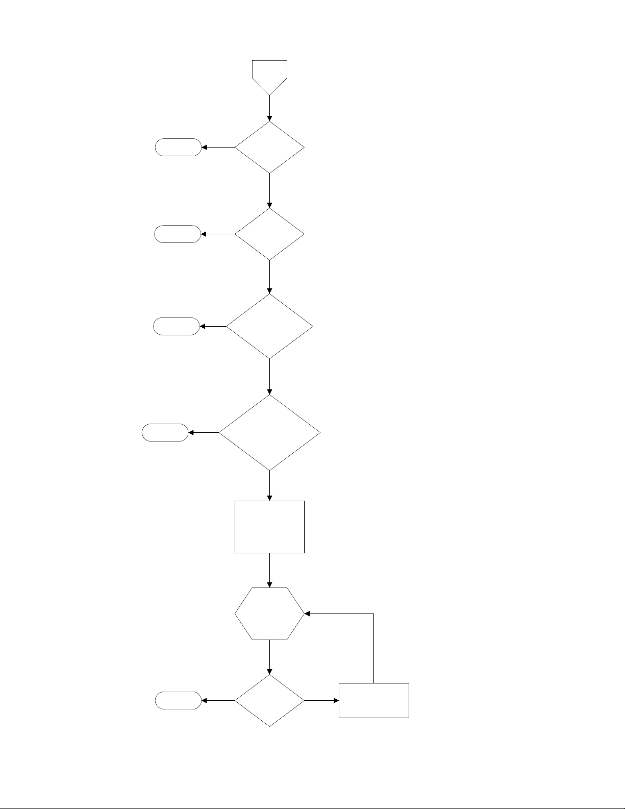
Email
Email Paging
Stop
Stop
Stop
Stop
No
No
No
No
Is Autopoller
running
Is Auto p olle r fla g
for this n o de set
Is "Enable Email
Alarm Page System"
checked in Autopoller
Are "Alarm De te c tio n " &
"Email on Alarm" checked
in AquaManager
Yes
Yes
Yes
Yes
Wait 60 seconds
minimum plus
node ping time
Send
Email
Stop
Yes
Has Alarm been
cleared
No
Wait for Pager
Retrans mit time
YSI Incorporated 74 5200 Recirculating System Monitor
Page 77

Stop
No
Power
Source
Has power source
changed
Yes
Power Alarm
Is Gerneral Alarm
enabled
No
Activate
Red LED
and
display
message
Is Pager
enabled
No
Is email
notification
enabled
No
Yes
Yes
Yes
Activa te
General
Alarm
relay
Send
Page
Email
Wait for Pager
Retransmit time
No
Has power
been restored
Yes
Send
Power
Good
Page
Stop
YSI Incorporated 75 5200 Recirculating System Monitor
Page 78

Auxilia ry
state
Auxiliar y Alarmin g
(digital mode only)
Stop
No
Is Auxiliary state =
alarm state
Yes
Is Alarm holdoff time
set to ze ro
Yes
Is Gerneral Alarm
enabled
No
Activ a te
beeper
and
display
message
No
this Auxiliary Input
Yes
Count down
holdoff time for
Activ a te
General
Alarm
relay
Is Pager
enabled
Yes
Send
Page
No
Email
YSI Incorporated 76 5200 Recirculating System Monitor
Page 79

7.2 General Alarm
Temperature
Alarm
DO Alarm
pH Alarm
General
Alarm
ORP Alarm
Con d uctivity
Alarm
Auxiliary A la rm
Alarm Light
or Buzzer
The General Alarm is a Summary alarm that activates a single device, such as a light or buzzer, whenever
any one of the individual parameter alarms is triggered. If the value of a parameter reaches the alarm low
or high point and the Alarm Hold Off time (See Section 9.2.3 Alarm Hold Off) has expired, an alarm
occurs. The status LED turns red showing which system(s) triggered the alarm (see 7.1 Alarm Logic Flow
Charts). The individual parameter alarm relay is activated (if a relay is assigned) and the General Alarm
is activated (if enabled). If the individual parameter alarm is enabled, the buzzer sounds and an alarm
page is sent (if the pager is enabled).
Reset the alarm by pressing the Enter key on the front of the 5200. Pressing the Enter key stops the
audible alarm and cancels any pending pages, but alarm status messages will NOT be cleared until the
5200 no longer senses the alarm condition.
Relay Disabled
Relay Disabled is the default setting for the General Alarm. It prevents the General Alarm from triggering
any relays (Internal or SubNet).
Relay Internal
Select Relay internal to trigger one of the four internal relays in this 5200.
Relay SubNet
Set the General Alarm to trigger an external subnet relay (connected to this 5200 via the RS485 network).
YSI Incorporated 77 5200 Recirculating System Monitor
Page 80

Section 8. Network
Multiple 5200 Recirculating Monitors can be connected together via their RS485 network ports (see 8.1
RS485 Network). Each network (group of connected 5200s) consists of 1 Master unit and up to 31 Slave
units. The default network Mode setting is Master.
NOTE: Each Slave in the network must have a unique Sub Address.
8.1 RS485 Network
The 5200’s optically isolated RS485 interface is located on the upper right hand corner of the I/O plate.
Up to 32 YSI 5200 Monitors can connected per network (1 master, 31 slaves). Each network requires a
PC COM port, so conceivably a PC could support multiple 32-instrument networks. This provides
significant flexibility in regard to alarming, monitoring and control.
The RS485 network wiring can span distances up to 4000 feet. If additional length is required, use an
RS485 Line Extender/Booster. Not using this device may cause communication failures. Mount the
booster in an area where it is protected from moisture.
NOTE: The 5200’s RS485 port is optically isolated. No further isolation is required.
Two snap-on ferrite assemblies, YSI# 655361, are included with the 5200 Monitor. Wires being
connected to the RS485 port need to be routed through the ferrites as shown in Figure 3-9. Failure to do
so could cause catastrophic monitor failure.
Terminal Connection Description (From left to right on I/O plate RS485 network connector)
1. T (-) Transmit to Network
2. T (+) Transmit to Network
3. R (-) Receive from Network
4. R (+) Receive from Network
8.1.1 Network Wiring
The network consists of 2 pair of twisted pair cable. Although, Category 3 and 4 cables can be used,
Category 5 Ethernet cable is recommended. Strip the wires about 2 times longer than necessary so that
they can be folded over and twisted to make a thicker connection. Below is an example with Ethernet
Category 5 cable. Note that this example color scheme is only applicable with category 5 wire:
Pair #1: Solid blue wire and white wire with blue stripe
Pair #2: Solid orange wire and white wire with orange stripe
The Master 5200 is wired as follows:
Wire Terminal Connection
Solid Orange Wire 1 T (-)
White w/Orange Stripe 2 T (+)
Solid Blue Wire 3 R (-)
White w/Blue Stripe 4 R (+)
NOTE: Install one 120Ω (ohm) resistor between T(+) and T(-) and one 120Ω (ohm) resistor between
R(+) and R(-) on the master 5200. Resistors are included with each 5200.
All 5200 slaves are wired as follows:
YSI Incorporated 78 5200 Recirculating System Monitor
Page 81

Wire Terminal Connection
Solid Blue Wire 1 T (-)
White w/Blue Stripe 2 T (+)
Solid Orange Wire 3 R (-)
White w/Orange Stripe 4 R (+)
NOTE: On the final slave in a string, install one 120Ω (ohm) resistor between T(+) and T(-) and one
120Ω (ohm) resistor between R(+) and R(-). Resistors are included with each 5200.
RS485 Wiring Diagram for 3 Networked 5200s
\ \ \ \
120 Ω
T(-) T(+) R(-) R(+)
Master
120 Ω 120 Ω
\ \ \ \
T(-) T(+) R(-) R(+)
T(-) T(+) R(-) R(+)
All other slaves
\ \ \ \
120 Ω
T(-) T(+) R(-) R(+)
Final slave
8.2 Auxiliary Inputs Wiring
The auxiliary inputs are configurable for a number of applications including monitoring level and/or
pressure switches. Both inputs have input protection, but the maximum input voltage should be no more
than 6 VDC. YSI recommends that twisted pair wire be used for these connections.
CAUTION: The auxiliary inputs are not isolated. Devices connected must be electrically isolated from
ground and the water.
CAUTION: Observe correct polarity on analog input. Do not apply negative voltage to analog input.
Two snap-on ferrite assemblies, YSI# 655361, are included with the 5200 Monitor. Wires being
connected to the Auxiliary ports need to be routed through the ferrites as shown in Figure 3-9. Failure to
do so could cause catastrophic monitor failure.
Auxiliary inputs can be configured as follows:
Input #1 – Digital (contact open/close w/current source)
Caution: Do not input external voltage.
Input #2 – User Defined (0 to 1.0 VDC, 0 to 5.0 VDC, or 4 to 20 mA selectable; max. 6.0 VDC) 10K
impedance
or
Digital (contact open/close w/current source)
Caution: Do not input external voltage.
NOTE: For proper digital input operation, use low impedance switches and wiring. The total resistance
should not exceed 200 ohms.
8.2.1 Example (Digital)—Installing a Float Switch
1. Install the float switch at the desired water level according to the manufacturer’s instructions.
YSI Incorporated 79 5200 Recirculating System Monitor
Page 82

2. Connect the switch to Auxiliary Input #1 or Auxiliary Input #2 using the 3-pole YSI 065942UL
Pluggable Socket Connector. See Figure 8-1.
Connect one wire to the ground (GND) terminal and the other to the In 1 or In 2 terminal.
NOTE: When connecting a switch to Auxiliary Input #2, set the input to Digital mode. See
Section 9.4.2 Input #2.
3. Set the 5200 to either Alarm on Open or to Alarm on Closed, depending on the type of switch
used. See Section 9.4.1 Input #1, Control.
IN 2 --
IN 1 --
GND--
Figure 8-1 Float Switch Wiring
8.2.2 Example (User Defined)—Connecting an Instrument
1. Connect the instrument to Auxiliary Input #2 using the 3-pole YSI 065942UL Pluggable Socket
Connector. See Figure 8-2.
2. Connect the negative wire to the ground (GND) terminal and the positive wire to the In 2
terminal.
3. For a 4–20mA input, connect a 250Ω resistor between the ground (GND) and positive In 2
terminals. See Figure 8-2.
4. Set Auxiliary Input #2 to User Defined mode and select the correct scale (0–1 VDC, 0–5VDC, or
4–20mA). See Section,9.4.2 Input #2.
YSI Incorporated 80 5200 Recirculating System Monitor
Page 83

IN 1 --
IN 2 --
GND--
IN 1 --
IN 2 --
GND--
Figure 8-2 Analog Instrument Connection
YSI Incorporated 81 5200 Recirculating System Monitor
Page 84

Section 9. Advanced Setup
Advanced Setup includes:
Ö System Menu Ö Timers Menu Ö Relay Output Wiring
9.1 System Menu
The System menu is used primarily during initial setup of the YSI 5200 Recirculating Monitor and
includes the following:
Ö Service
Ö Communications
Ö Password
Ö Display
Ö Downloader
Ö General Alarm
Ö Display Address
Ö Data
Ö Locale
YSI Incorporated 82 5200 Recirculating System Monitor
Page 85

System Menu
Data Logger
LocaleData Service PasswordCommunications
Display Address DownLoader
Set Date MM/DD/YYYY
Set Time
Locale USA/Intl
Set Interval
1-3600 minutes
HH:MM:SS
General Alarm
No
Enabled
Display Speed 1-20
Yes
Set Password XXXXXXXXXXXX
Display Mode Normal/Inverse
Display
Yes/No
Clear Data
Print Data
Log Events Yes/No
Entire Log
Continue Y/N
Entire Log
Current Log
Enabled
Select
Relay
Figure 9-1 Systems Menu
No
YSI Incorporated 83 5200 Recirculating System Monitor
Page 86

9.1.1 Service
Service menu selections are shown below.
Service Menu
System Test
R1
R2
R3
R4
On/Off
On/Off
On/Off
On/Off
Clean Probes
Enabled
Yes
Duration
Reset
No
0-180 Days
Reset To Factory
Yes/No
Yes/No
Figure 9-2 Service Menu
Clean Probes
This feature reminds the user when it is time to clean the probes by scrolling a text message across the
display.
Duration
In the example above, a message will scroll across the bottom of the display after 45 days indicating it is
time to clean the probes.
YSI Incorporated 84 5200 Recirculating System Monitor
Page 87

Reset
After the set number of days has passed and the Clean Probes message appears on the display, it must be
reset.
Reset to Factory
CAUTION: Reset to Factory returns all the settings to the factory default values (see Section 16 Factory
Default Settings). All calibration values, alarms, set point values and control functions will be lost. If
you are sure you want to return to the factory settings, proceed as follows:
System Test
Use System Test to verify that each control system is working correctly. See Section 5.5 Conducting a
System Test for details.
YSI Incorporated 85 5200 Recirculating System Monitor
Page 88

9.1.2 Communications
Communications menu selections are shown below.
Communications
Menu
No
Enabled
NetworkSerial SettingPager
Master
Set as Master
Yes
Pager Phone
Number
Pager Delay
Pager Retries
Pager Retransmit
Tone/Pulse Tone
Page Now
(XXX) XXX-XXXX
Delay 0-60 Seconds
Delay 0-60 Minutes
Delay 0-60 Minutes
Pulse
Baud Rate
Slave
Set Sub Node
Address
19200
9600
2400
1200
300
Figure 9-3 Communications Menu
Pager
The Pager feature allows you to receive 5200 alarm messages on your numeric pager. If a parameter
enters the alarm range, its status indicator (on the front of the 5200) will change to solid red (see 7.1
YSI Incorporated 86 5200 Recirculating System Monitor
Page 89

Alarm Logic Flow Charts). After the Alarm Hold Off period expires, the audible alarm (a standard
feature) will activate. If the 5200 is configured and enabled for alarm pager support, an alarm page will be
sent indicating which parameter is in alarm state (pH, ORP, Temperature, etc.) and the type of alarm it is
(high alarm, low alarm, etc.). This information is transmitted via modem (the 5200’s modem or a
computer running AquaManager software and equipped with a compatible modem) to your pager. The
page consists of the last three digits of the serial number of the YSI 5200, followed by a seven digit alarm
code as indicated below.
N N N Y Y Y Y Y Y Y
Aux Input 2
Aux Input 1
DO
Conductivity
Temperature
ORP
pH
5200 Serial Number
Figure 9-4 Pager Alarm Parameter Identification
After the serial number of the unit, the first digit always refers to pH status, the second digit indicates
ORP status, the third digit indicates temperature status, the fourth digit is conductivity status, the fifth is
DO status and the last two digits are Aux Input #1 and Aux Input #2. Table 9-1 shows the possible alarm
conditions and the codes that are displayed. Note that a “0” in any digit location indicates that no alarm
condition occurred for that parameter.
pH ORP Temperature Conductivity DO Aux Input 1 Aux Input 2
Low Alarm 1 1 1 1 1 1 1
High Alarm 2 2 2 2 2 1 1
Both High & Low Alarms 3 3 3 3 3 n/a n/a
Main Power Restored 0 0 0 0 0 0 0
On Battery Power 8 8 8 8 8 8 8
Table 9-1 Pager Alarm Codes
NOTE: The 5200 also sends code 8888888 if back-up power is lost, but primary power is still present.
As an example, an alarm for a YSI 5200 unit with serial number 52-003598 was activated, indicating a
high pH and low ORP condition, the page would appear as follows:
“598 2100000”
If your system has backup power, you will receive pages through the power fail detect feature. If power
fails on a unit that has no backup battery, when the power comes back on, the unit will dial the phone
pager and send a power out message. (All zeros mean the unit has powered back up after a power outage.)
Pager Phone Number
The first step in programming the YSI 5200 for pager support is the entry of the phone number you want
the 5200 to dial in the event of an alarm condition.
Dial Modifiers
Depending on your situation, you may need to use the dial modifiers listed below. These are special
parameters that tell the modem what, when and how to dial the telephone number.
YSI Incorporated 87 5200 Recirculating System Monitor
Page 90

Dial Modifier Description
, Delay for approx. 1 second
W Wait for dial tone
The ‘W’ dial modifier is particularly important to make sure that there is a “dial tone” before initiating a
page.
Pager Phone Number Example
The following is an example of one scenario where the pager number requires a bit more than the phone
number:
To reach the pager, it is necessary to:
• Dial 9 for an outside line.
• Wait for the dial tone.
• Dial the paging company.
• Wait a few seconds for the paging company to answer the phone and accept a pager input.
The pager number to be used in this example would be:
9W16195551212
NOTE: To perform the last step (Wait a few seconds…), see the Pager Delay Section below.
Pager Delay
Every pager service company processes pager calls differently. It is important that the YSI 5200 does not
start sending information before the pager company is ready to receive it.
The pager delay time is the number of seconds that the YSI 5200 waits after it has dialed the phone
number before it sends the serial number and alarm values. For example, if your pager service has a
message that precedes the transmission of a page, you will need to time the message period and program
this time period into the Pager Delay. If the interval is set for too short a period, the serial number and
alarm code will not be properly processed by the paging system. If the time period is set for too long a
period, then the pager service company may terminate the call before the alarm code information is sent.
A good starting value is 5-10 seconds.
Pager Retries (Redial)
The pager retry timer is activated if the YSI 5200 is unable to send a page due to a busy phone line. The
controller will wait the number of minutes specified by this command and attempt to send another page.
The default value is 3 minutes. Valid times are from 0 to 120 minutes.
Pager Retransmit (Until Reset)
When an alarm condition is detected (and after the hold-off period has expired), the 5200 will send a
pager alarm. The YSI 5200 is programmed to continue paging until the alarm is reset (someone physically
pushes a key on the front of the YSI 5200).
The pager retransmit value sets the length of time that the controller waits before it pages again—
assuming that the alarm has not been reset.
Pager Tone/Pulse
The Tone/Pulse setting controls whether the modem uses tone or pulse dialing. If you have a rotary
phone, select pulse as shown below; otherwise, use the default setting, tone.
YSI Incorporated 88 5200 Recirculating System Monitor
Page 91

Page Now
Page Now sends a test page consisting of the last 3 digits of the serial number of the 5200 followed by
999. As an example, for a YSI 5200 with serial number 52-003598, the page would appear as follows:
“598 999”
Serial Setting
The only Serial Setting selection is Baud Rate.
Baud Rate
The baud rate is the speed that the YSI 5200 transmits data via the serial IP port. It can be set at 300,
1200, 2400, 9600 or 19,200 baud. The default value (19,200 baud) will work with 90% of the modems in
use today. If you are using AquaManager software, the baud rate must be set to 19,200.
Network
Multiple 5200s can be connected together via their RS485 network ports (see 8.1 RS485 Network).
9.1.3 Password
Use the password feature to protect your 5200 from unauthorized use. Anyone attempting to use the 5200
will not be able to enter the menus unless they enter the correct password.
NOTE: If you choose not to use the password protection, do not enter any password. Move to the next
setup procedure, Section 9.1.4 Display.
Once you have enabled and entered a password, you will be prompted to enter it when attempting to
access any menus from the Run screen. In order to disable it in the future, you will have to know the
Password, enter the System Menu, select Password and select No for Enabled?
Do not forget your password!
9.1.4 Display
The only Display selection is Display Speed.
Display Speed
Display Speed controls how quickly the Run screen scrolls through the parameter readings. The higher
the value entered, the longer the display will remain on each parameter. The allowable range is 1–20,
corresponding to an actual display time of 1–6 seconds per parameter.
9.1.5 Downloader (Upgrading Software)
Use Downloader to upgrade the 5200 software.
1. Access the YSI Environmental web site Downloads page at http://www.ysi.com/edownloads to
download the latest version of the 5200 Code Updater software.
2. Click on the YSI Instruments Software Updates link (or scroll down until you see YSI 5200).
3. Click on the file icon to the right of the YSI 5200 listing and save the file to a temporary directory
on your computer.
4. Uninstall any previously installed versions of the YSI 5200 Code Updater from your computer.
YSI Incorporated 89 5200 Recirculating System Monitor
Page 92

5. After the download is complete, run the file (that you just downloaded) and follow the on screen
instructions to install the YSI 5200 Code Updater on your computer. If you encounter difficulties,
contact YSI customer service for advice. Refer to Section 14 Warranty and Service Information.
6. Connect the YSI 5200 to a serial port of your computer using the YSI 655384 Network Cable and
YSI 655383 RJ-45 to DB-9 Adapter (or YSI 5285 Opto-isolator).
NOTE: The 5200 must be on and displaying the Run screen. It must also be in Master mode (see
9.1.2 Communications) and have 120Ω resistors installed on the RS485 connection as described
in 8.1.1 Network Wiring. Paging must be disabled (see 9.1.2 Communications, Pager).
7. Run the YSI 5200 Updater software that you previously installed on your computer. The
following window will be displayed:
Select Comm port
Click on
UPDATE HEX CODE
8. Set the Comm Port number to match the port that you connected the 5200 to.
9. Click on the [UPDATE HEX CODE] button.
The YSI 5200 screen will count up as the code is updated.
DOWNLOADER V2.9f
Writing 294C6
A progress indicator will be displayed on the PC as shown below.
Progress Indicator
When the update is finished, the YSI 5200 will return to the Run screen.
10. Close the YSI 5200 Code Updater window (on the PC) by clicking on the "X" in the upper right
corner of the window.
11. Disconnect the YSI 5200 from the computer.
YSI Incorporated 90 5200 Recirculating System Monitor
Page 93

12. Disconnect power from the 5200.
13. Reapply power to the 5200.
9.1.6 General Alarm
See Section 7.2 General Alarm for a detailed description.
9.1.7 Display Address (Serial Number)
Displays the Address (serial number) of the 5200 on the screen. The Address and software version are
also displayed whenever the 5200 is powered on.
9.1.8 Data
The 5200 has a 32K volatile memory, allowing it to log 750 sample data sets. The logging rate is user
selectable. Data menu selections are Data Logger, Clear Data, Print Data and Log Events.
Data Logger
Select Data Logger to enter the desired Data Logging time interval.
Clear Data
Clear Data erases all logged data stored in the 5200’s memory.
Print Data
Use Print Data to send logged sample data via the 5200’s RS232 serial port to a computer equipped with
any standard communications software. See Section 3.7.1 RS232 and TCP/IP Port for wiring
connections.
Entire Log
Sends the Entire Log to a computer via the 5200’s RS232 port. The output is tab delimited ASCII text
that can be imported into a spreadsheet. The format is shown below. Headings are not included in the
output.
Date Time pH ORP Temp Cond DO DO% A1A2 AC CS
05/17/2001 09:32:29AM 6.97 209mV 76.6F 187uS 17.22 207 0 0 0 136
05/17/2001 09:38:04AM 6.97 209mV 76.8F 221uS 13.04 157 0 0 0 146
05/17/2001 09:43:04AM 6.97 209mV 76.8F 227uS 12.80 154 0 0 0 144
05/17/2001 09:48:04AM 6.98 209mV 76.8F 249uS 12.70 153 0 0 0 136
A1—Auxiliary Input #1. 0 or 1
A2—Auxiliary Input #2. Digital mode, 0 or 1
AC— Auxiliary Input #2. Analog mode, Analog Counts (4096 counts = full scale)
CS—Check Sum
Current Log
Sends the Current Log (current readings) to a computer via the 5200’s RS232 port. The format is
identical to the Entire Log format shown above. Note that the data sent is the current reading from the
sensors not the last logged data point.
YSI Incorporated 91 5200 Recirculating System Monitor
Page 94

Log Events
The 5200 can Log Events performed, such as a control system, alarm, or timer turning on or off. YSI
AquaManager software is required to display logged events.
9.1.9 Locale
The YSI 5200 is equipped with an internal clock/calendar with its own backup battery. The
clock/calendar is set from the factory, but you may need to adjust it to your time zone. Selections are:
Ö Set Date
Ö Set Time
Ö Set Locale—USA or International
YSI Incorporated 92 5200 Recirculating System Monitor
Page 95

9.2 Timers Menu
The Timers Menu includes options for the YSI 5200 to control various timers including:
Ö Feed Timer
Ö Service Hold
Ö Alarm Hold Off
Ö Timer 1
Ö Timer 2
Ö Timer 3
Ö Timer 4
Timers Menu
Feed Timer
Service Hold
Alarm Hold Off
Timer 1
Timer 2
Timer 3
Timer 4
Enabled
Enabled
Enabled
Enabled
Enabled
Enabled
Yes
0-3600 Sec
0-3600 SecYes
Stop TimeStart TimeYes
Stop TimeStart TimeYes
Stop TimeStart TimeYes
Stop TimeStart TimeYes
Select
Relay
Select
Relay
Select
Relay
Select
Relay
Figure 9-5 Timers Menu
YSI Incorporated 93 5200 Recirculating System Monitor
Page 96

9.2.1 Feed Timer
The Feed Timer System allows control and monitoring of feedings made by the 5200. Optional Parameter
control reduces the amount of food dispensed if the DO, temp or pH values are “out of range.” Feed
Timer parameter controls work independently of the 5200 parameter setpoint menus and operation. The
optional FCR (feed conversion ratio) feature automatically increases the daily amount of food dispensed.
For proper operation, the Feed Timer System requires the user to enter the total amount of food to be
dispensed, number of feedings that total amount of food will be dispensed in, and a defined time period
within which the feedings will occur.
It is also important that the 5200 be configured with valid data. The feeder system will not operate
properly, if, for example, the daily weight of food is greater than can be dispensed in the defined time
period.
Feed Timer menu selections are shown below.
YSI Incorporated 94 5200 Recirculating System Monitor
Page 97

Feed Timer
Enabled
Yes
No
TestSetup
Calibrate Feeder only available
when a relay is enabled
Feeder
Feed Days
Start Date
End Date
Feed Mode
Start Time
SMTWTFS
Timed/
Continuous
FCR Parameter Setup Menu
Enabled
Biomass
Feed %
Biomass
Daily Weight
FCR Factor
Enabled
DO Low
DO High
DO Change
Temp Low
Temp High
Temp Change
Relay
Units
Calibrate Feeder
Time Elapsed
Measured Weight
Select
Relay
Oz,lb,g,kg
001-500
seconds
End Time
Daily Weight
Daily Feedings
Start Time and End Time only
available when Feed Mode is Timed
Daily Weight only available when
FCR is disabled
pH Low
pH High
pH Change
Figure 9-6 Feed Timer Menu
YSI Incorporated 95 5200 Recirculating System Monitor
Page 98

Feeder
Prior to operating the feed timer system, the following fields must be configured:
Ö Feed Days—days of the week feedings will occur
Ö Start and End Dates—dates within which the feed timer system will operate
Ö Feed Mode—feed cycle type (timed or continuous)
Ö Daily Feed Amount—daily weight of food to be dispensed
Ö Daily Feedings—number of feedings to occur per feeding cycle
Feed Days
Select the days of the week that feeding(s) should occur. Enter “Y” (yes, feed cycle(s) to occur on
selected day) or “N” (no, feed cycle(s) not to occur on selected day).
Continuous feed mode
In continuous feed mode, feeding(s) will end after the last completed feeding that ends prior to 11:59 pm
(23:59) of the day before an “N” day. Feeding(s) will resume at 12:00 am (00:00) for the next feeding day
that is tagged “Y”.
Timed feed mode
If a timed feed cycle includes feed times that cross midnight, the feed cycle will complete regardless of
operating (finishing the feed cycle) on an “N” day.
Example—with the following days selected
S M T W T F S
N N Y Y Y Y Y
and start time set to 10:00 pm (23:00) and end time set to 01:00, a Saturday feeding would complete any
feedings on Sunday (even though it’s tagged N, because the timed feed cycle began on a “Y” tagged day).
The feed cycle will not start again until 10:00 pm on Tuesday. No feeding would occur Monday, because
Monday is an “N” day even though the feed cycle crosses midnight and Tuesday is “Y” day.
Start Date
Enter the date the feed cycle(s) will begin.
End Date
Enter the date the feed cycle(s) will end. Note that no feed cycles will occur if this date is not set.
Continuous feed mode
In continuous feed mode, feeding(s) will cease after the last completed feeding that occurs with an end
time prior to 11:59 pm (23:59) of end date.
Timed feed mode
If a timed feed cycle crosses midnight, the feed cycle will complete regardless of operating during the day
beyond end date.
Feed Mode
Select Timed feed mode if feedings are to occur only during certain times of the day. If Timed feed mode
is selected, the user will need to enter Start and End Times.
YSI Incorporated 96 5200 Recirculating System Monitor
Page 99

Select Cont. (Continuous) if feedings are to occur over the entire day. Once a Continuous feed
configuration has been configured, the 5200 determines any remaining feeds for the 24 hour period,
ending at 23:59. In continuous feed mode the feed cycle always begins at 00:00 (midnight). Start and End
time fields are not available options for Continuous feed mode.
Start Time
Select the time the 1st feeding should occur (in 24 hour format). If configuration of timed feed mode is
done during a feed cycle, the 5200 calculates the number of feeds and their intervals for the remainder of
the time period.
st
In timed mode, the 1
feeding will always occur at the start time of the feed cycle.
End Time
Select the time the last feeding should be completed by. Because of the way the 5200 determines feed
cycle durations and intervals, the end time will occur during the last feed cycle interval, not at the end
time of the last feed cycle feed duration.
Daily Feed Amount
This is the total weight of food that will be dispensed over the feeding time period. The value is user
selectable from 000.1–999.9. The Feed Timer system divides the total daily feed amount by the number
of daily feedings and uses the calibration/test data to determine feed cycle duration times.
Daily Feedings
Enter the number of feedings per feed cycle time period; 1–99.
Note: Any change to feed timer configuration resets the feed timer system.
FCR
The optional FCR (feed conversion ratio) feature automatically increases the amount of food dispensed
over a feed cycle. The increase in the amount of food is based on the user selected increase in biomass
over a 24 hour period. Biomass and daily (feed) weight amounts are adjusted by the 5200 prior to the 1
feed “on” time of a scheduled feed cycle occurring after midnight.
NOTE: If changes are made to the FCR settings during a feed cycle, they do not take effect until the
following feed cycle.
st
Biomass
Enter the total weight of all fish being fed at the time FCR is enabled; 1–32767.
Feed % (of) Biomass
Enter the percentage of the total fish weight (biomass) that will be used to determine the daily feed
weight; 0.1–9.9%.
Daily (Feed) Weight
Input the initial daily feed weight by multiplying the biomass amount by the Feed % Biomass percentage
(the 5200 will not calculate the initial amount). For example—if the biomass is 1000 and the feed %
biomass is 3%, the initial daily feed weight amount is 30. On each following day, the 5200 will use the
biomass value along with the feed % biomass to automatically calculate this value.
FCR Factor
Enter the ratio of the amount of food required vs. the corresponding increase in fish weight (biomass).
This value is used to automatically increase the biomass amount—as shown in the example below.
YSI Incorporated 97 5200 Recirculating System Monitor
Page 100

Day1 Day 2 Day 3 Day 4 Day 5 Day 6 Day 7
Biomass 1000 1020 1040 1061 1082 1104 1126
Feed % (of) Biomass 3% 3% 3% 3% 3% 3% 3%
Daily Feed Amount 30 30.6 31.2 31.8 32.5 33.1 33.8
FCR Factor 1.5 1.5 1.5 1.5 1.5 1.5 1.5
1/FCR x Feed Amount 20 20.4 20.8 21.2 21.6 22.1 22.5
New Biomass 1020 1040 1061 1082 1104 1126 1149
Parameter
Changes in water parameter conditions will affect the amount of food fish eat and thus will affect fish
growth. With the parameter feature enabled, the feed timer system will verify that pH, temperature and
DO values are within user selected ranges. This verification is done immediately prior to starting each
feed cycle duration. If the values are outside these ranges, food weight amount is reduced by a user
selected percentage.
DO/Temp/pH Low
Enter the lower limit of the parameter range where no feed compensation will take place.
DO/Temp/pH High
Enter the high limit of the parameter range where no feed compensation will take place.
DO/Temp/pH Change
Enter the percent reduction in feed weight that will occur for each 1/10 unit of measure the parameter is
out of range. Results from all out of range parameters are added.
Setup Menu
Relay
Assign a relay address to the feeder.
NOTE: Feed calibration cannot be performed if the Relay is disabled.
Units
Select lb (pound), g (gram), kg (kilogram), or oz (ounce) as the unit of weight the Feed Timer System
uses for the calibration/test sample amount and to the total daily feed amount.
NOTE: If the units are changed, the feeder must be recalibrated.
Test
Calibrating (Testing) the feeder is essential for proper operation of the Feed Timer System. Calibration
will determine the rate at which food is dispensed from a feeder. This information is used to determine
feed cycle duration(s).
NOTE: A relay must be assigned in order to enter the Calibrate Feeder menu.
Calibrate Feeder
Enter the amount of time the feeder relay will be energized for testing; 001–500 seconds. The relay will
energize after the last digit is entered. After the timer counts down to zero, the feed relay deenergizes and
the Measured Weight screen is displayed.
YSI Incorporated 98 5200 Recirculating System Monitor
 Loading...