

Page 1
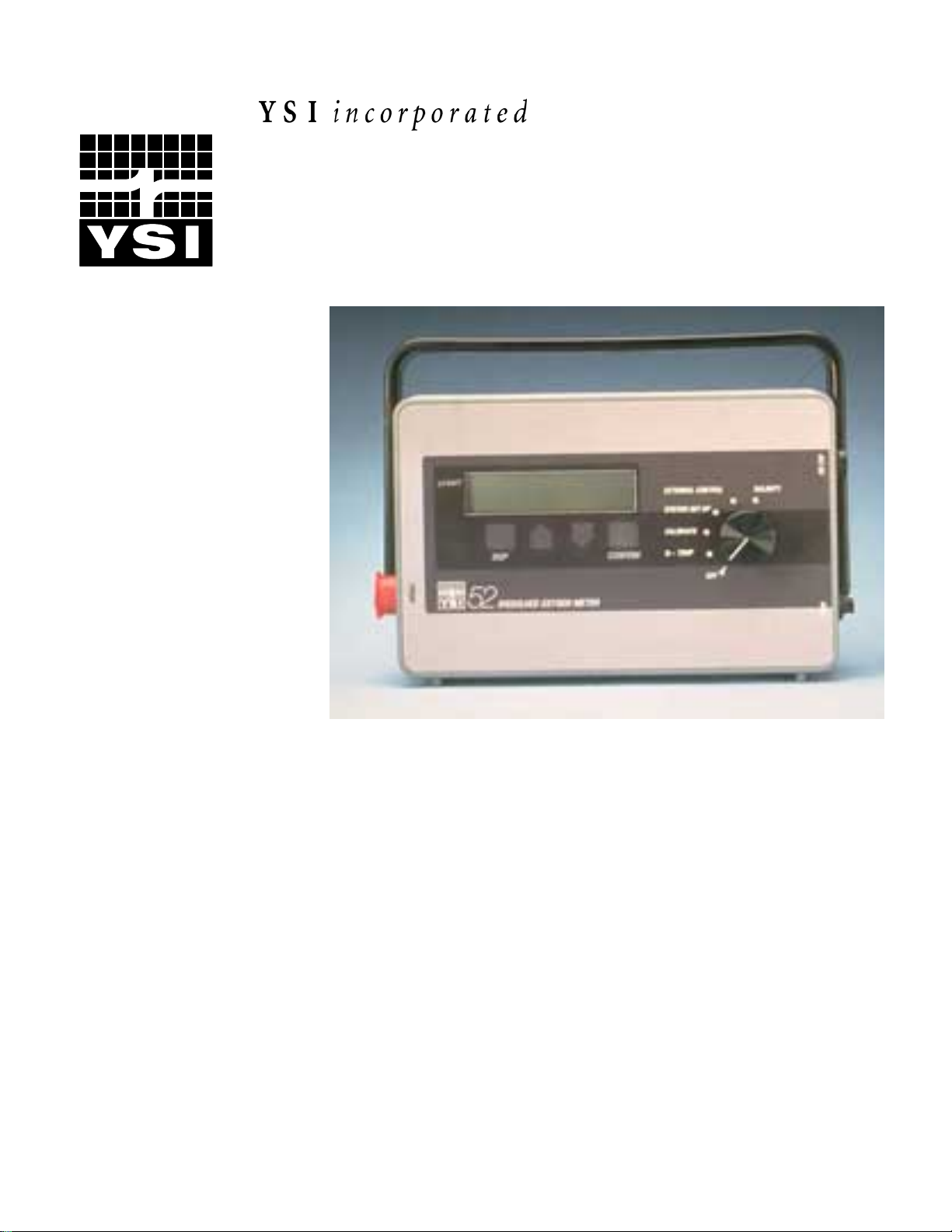
YSI Model 52
Dissolved Oxygen Meter
Operations
Manual
Page 2

Page 3

CONTENTS
SECTION 1 INTRODUCTION................................................................................................................. 1
1.1 PRINCIPLES
1.2 DISPLAY
1.3 FUNCTION
1.4 POWER
OF OPERATION...................................................................................................... 1
AND FUNCTION KEYS............................................................................................... 2
SWITCH ..................................................................................................................... 2
ON SELF-TEST................................................................................................................ 2
SECTION 2 PREPARING THE METER ............................................................................................... 3
SECTION 3 CALIBRATION ................................................................................................................... 5
PERCENT AND MG/L.................................................................................................................... 5
3.1
3.2 DETERMINING
3.3 CALIBRATION
3.4 CALIBRATION
3.5 CALIBRATION
3.6 ZERO
CALIBRATION ................................................................................................................... 8
3.7 RESETTING
CALIBRATION VALUE....................................................................................5
IN AIR.................................................................................................................. 6
IN AIR-SATURATED WATER.......................................................................... 7
BY WINKLER TITRATION............................................................................... 7
THE DEFAULT ZERO CALIBRATION ............................................................... 10
SECTION 4 SALINITY........................................................................................................................... 11
SECTION 5 OPERATION...................................................................................................................... 13
5.1 TEMPERATURE
5.2 DISSOLVED
5.3 MEASURING
5.4 RECORDING
5.5 REVIEWING
5.6 PRINTING
5.7 SENDING
5.8 ERASING
MEASUREMENTS ......................................................................................... 13
OXYGEN MEASUREMENTS .............................................................................. 13
OXYGEN IN FLUIDS OTHER THAN WATER.................................................. 13
TO INTERNAL MEMORY................................................................................... 14
RECORDED LIVE DATA..................................................................................... 15
DATA FROM MEMORY .......................................................................................... 16
RECORDED DATA TO A PERSONAL COMPUTER .............................................. 16
THE MODEL 52 MEMORY ....................................................................................... 17
SECTION 6 SYSTEM SETUP................................................................................................................18
6.1 SETTING
6.2 SETTING
6.3 SETTING
6.4 LAST
6.5 CONTRAST
THE TIME AND DATE............................................................................................... 18
UP AUTOSTABLE...................................................................................................... 18
COMMUNICATION PARAMETERS ........................................................................ 20
DIGIT SUPPRESSION....................................................................................................... 21
ADJUSTMENT........................................................................................................ 21
SECTION 7 PERSONAL COMPUTER INTERFACE........................................................................ 23
7.1 WRITING
YOUR OWN APPLICATIONS SOFTWARE ............................................................ 23
SECTION 8 MAINTENANCE AND TROUBLESHOOTING............................................................ 25
8.1 BATTERIES.................................................................................................................................. 25
8.2 POWER
ON SELF-TESTING AND ERROR DISPLAY MESSAGES ........................................ 25
SECTION 9 DISCUSSION OF MEASUREMENT ERRORS............................................................. 27
9.1 TYPE
9.2 TYPE
9.3 TYPE
9.4 ERROR
1 ERRORS – INSTRUMENT COMPONENTS.................................................................. 27
2 ERRORS – PROBE ACCURACY ................................................................................... 27
3 ERRORS - CALIBRATION............................................................................................. 28
CALCULATION EXAMPLE.......................................................................................... 28
SECTION 10 WARRANTY AND REPAIR ...................................................................................... 31
i
Page 4

AUTHORIZED
CLEANING
PACKING
U.S. SERVICE CENTERS............................................................................................ 32
INSTRUCTIONS............................................................................................................... 34
INSTRUCTIONS.................................................................................................................. 34
APPENDIX A GENERAL SPECIFICATIONS................................................................................... 37
APPENDIX B REQUIRED NOTICE ................................................................................................... 39
APPENDIX C OXYGEN SOLUBILITY.............................................................................................. 41
APPENDIX D CALIBRATION TABLES............................................................................................ 43
ii
Page 5

SECTION 1 INTRODUCTION
The YSI Model 52 is a microprocessor-based instrument designed for field and
laboratory measurement of dissolved oxygen. Readings are automatically compensated
for temperature. When calibrated to percent air saturation, the display simultaneously
shows dissolved oxygen in mg/L and in percent air saturation as well as temperature in
degrees Celsius.
An RS232 port permits results to be sent directly to your serial printer or personal
computer. Salinity compensation can be adjusted manually. To assure the highest
accuracy, an auto stable feature indicates when the readings have reached user-defined
criteria for stability. To assure correct operation, the meter performs a self-testing routine
each time it is turned on; any error is then signaled on the display.
Calibration is quick and easy. Procedures for calibrating with and without compensation
for temperature, altitude, pressure, and salinity are described in this manual. The YSI
Model 52 is also equipped with non-volatile memory, capable of storing up to 70 DO and
temperature readings. Any data stored in internal memory can be reviewed on the LCD,
or batch uploaded to a PC or an RS232 printer.
Power can be provided by an AC adapter (optional), or batteries that permit field use.
1.1 PRINCIPLES OF OPERATION
YSI dissolved oxygen probes use membrane covered, Clark-type polarographic sensors
with built-in thermistors for temperature measurement and compensation. A thin semi
permeable membrane, stretched over the sensor, isolates the sensor elements from the
environment, but allows oxygen and certain other gases to enter. When a polarizing
voltage is applied across the sensor, oxygen that has passed through the membrane reacts
at the cathode, causing a current to flow.
Oxygen diffuses through the membrane at a rate proportional to the pressure difference
across it. Since oxygen is rapidly consumed at the cathode, it can be assumed that the
oxygen pressure inside the membrane is zero. Hence, the amount of oxygen diffusing
through the membrane is proportional to the absolute pressure of oxygen outside the
membrane. If the oxygen pressure increases, more oxygen diffuses through the
membrane and more current flows through the sensor. A lower pressure results in less
current.
YSI, Incorporated Model 52 1
Page 6

Introduction Section 1
1.2 DISPLAY AND FUNCTION KEYS
A rotary function switch and four keys provide complete control of the Model 52. The
four keys are SKIP,¿ ,À , and CONFIRM. ¿ andÀ are used to modify a setting
either up or down (for example, calibration or salinity values can be modified for each
calibration process if required). The CONFIRM key is used to accept your setting.
The display often asks questions such as “Calibrate in percent?” Use CONFIRM to
answer yes. Use SKIP to go on to the next choice. The SKIP key can also be used to
select among several default values.
1.3 FUNCTION SWITCH
The rotary function switch allows easy selection among the meter’s basic functions. In
O
-TEMP, the instrument is measuring dissolved oxygen and temperature. To begin
2
calibrating, switch to CALIBRATE. To begin setting the clock, communication, and
auto-stable parameters, switch to SYSTEM SETUP. EXTERNAL CONTROL activates
the RS232 port. Salinity can be set after switching to SALINITY.
1.4 POWER ON SELF-TEST
A Power On Self-Test (POST) takes place whenever the meter is turned on. This ensures
correct performance. If anything is wrong, the operator is signaled and the error
identified. An error message will appear on the display. For more information see Section
8.2, Power On Self-Testing and Error Display Messages.
YSI, Incorporated Model 52 2
Page 7

SECTION 2 PREPARING THE METER
To prepare the meter for use, connect a prepared probe to the meter. Set the function
switch to O
Autostable. Since complete equilibration can take as long as 15 minutes after the meter is
turned on, it is customary to leave the instrument on throughout the working day.
When the instrument is turned on, a beep signals the beginning of a Power On Self Test
(POST). A series of displays will appear. A final beep and a return to the normal display
signal the conclusion of the test. The whole process takes about 10 seconds. If the
instrument detects an error, it will display an error message. These messages, with
appropriate corrective actions, are listed in the Maintenance and Troubleshooting section
of this manual. If you have a problem you cannot resolve, call YSI Technical Support,
(937) 767-7241 or (800) 765-4974.
-TEMP. Observe temperature and oxygen readings for stability, or set up
2
6.33 mg/L 19.9C
Stirring: Since the oxygen level in the layer of liquid at the membrane surface is
continuously depleted, it is essential that water movement of 1 foot per second or more
be maintained while making dissolved oxygen measurements. When using the Model 52
in field applications, a moving stream will usually provide adequate motion, as will
moving the probe through the sample by hand. For lab applications, we recommend one
of the YSI self-stirring BOD probes.
When the temperature and oxygen readings have stabilized, you are ready to begin
calibration.
88.1 % 11: 52
YSI, Incorporated Model 52 3
Page 8

Preparing the Meter Section 2
YSI, Incorporated Model 52 4
Page 9

SECTION 3 CALIBRATION
Calibration is accomplished by exposing the probe to a known concentration of oxygen
and then adjusting the calibration value to match. Since the oxygen content of our
atmosphere varies predictably according to relative humidity and atmospheric pressure,
we recommend that you calibrate in air, see Section 3.3, Calibration in Air.
Daily calibration is usually appropriate. Calibration can be disturbed by a physical shock,
touching the membrane, fouling of the membrane or drying out of the electrolyte. Check
calibration after each series of measurements, and in time you will develop a realistic
schedule for recalibration.
3.1 PERCENT AND MG/L
100 percent air saturation corrected to standard pressure is the dissolved oxygen value of
water saturated with air at 760 mm Hg (1013 millibars or 29.92 inches Hg). The mg/L
values describe the concentration of oxygen. Since calibrations in mg/L do not
necessarily yield correct percent readings, the percent readings are disabled after
calibrations in mg/L. Calibrations in percent are correct for both percent and mg/L
readings.
3.2 DETERMINING CALIBRATION VALUE
Typically, local barometric pressure is not equal to "standard pressure." Therefore, unless
you are calibrating with a known sample determined by a Winkler titration, you should
determine the proper calibration point for the local barometric pressure. This corresponds
to a reading from a mercury barometer. Do not use the pressure reported by the Weather
Bureau that has been adjusted to sea level. The calibration value for a given barometric
pressure can be read from the chart on the back of the meter, or the one in Appendix D of
this manual.
The chart also lists calibration values according to altitude. These values are only
approximate because they are derived from the average pressure at the given altitudes,
and do not take pressure variations into account. The typical error resulting from
calibration to altitude alone will be ±4% of your reading. Use altitude values only when
you cannot determine the true barometric pressure.
YSI, Incorporated Model 52 5
Page 10

Calibration Section 3
3.3 CALIBRATION IN AIR
Three separate calibration techniques are discussed here: calibration in air, calibration in
air-saturated water, and calibration by Winkler titration. Choose the one technique which
best fits your application. Calibration in air is the simplest and most accurate method of
calibration.
To calibrate in air:
1. Place a prepared probe in air at 100% relative humidity. To achieve this, BOD probes
can be placed in a BOD bottle with approximately 1” of water. Field probes can be
placed in the plastic calibration bottle with a moistened sponge, or calibrated with the
5075A Calibration Chamber.
2. Switch to CALIBRATE. The display will read:
Select percent calibration by pressing CONFIRM. A display similar to the one below
will be shown.
3. Using ¿ and À, adjust the number to the calibration value determined from the
altitude or pressure chart on the back of the Model 52. SKIP sets the value to 100.0%;
and shows the following display:
you may wish to do this to bring the setting quickly to a value near the one you want,
then continue with ¿ and À. Pressing SKIP again sets the value to 0.0% (see Zeroing
the Probe). Pressing SKIP a third time brings it back to the last calibration value.
E n t e r c a l v a l u e
L a s t = 9 6. 4 %
E n t e r c a l v a l u e
S a t . = 1 0 0 %
C a l i b r a t e
i n p e r c e n t ?
YSI, Incorporated Model 52 6
Page 11

Calibration Section 3
4. When you have adjusted the reading to the desired value (let’s say you chose 98.0%),
press CONFIRM. The instrument will display the legend “Please wait” for a few seconds.
Then it will display:
You are now ready to measure dissolved oxygen.
C a l i b r a t e d t o
9 8. 0 %
3.4 CALIBRATION IN AIR-SATURATED WATER
A second alternative for calibration is to calibrate in air-saturated water. This procedure
is the same as the procedure for calibration in air except that the calibration medium is
saturated water rather than saturated air.
To calibrate in air-saturated water:
1. Air-saturate a volume of water (300 to 500 mL) by aerating for at least 15 minutes at a
relatively constant temperature.
2. Place the probe in the sample and provide adequate stirring (at least 1 foot per second).
Switch to O
take 5 minutes for the temperature to come to equilibrium. If you have just turned the
instrument on, allow 15 minutes for the system to equilibrate.
3. Switch to CALIBRATE, select percent calibration, then adjust the number in the
display to the correct value based on current barometric pressure or altitude and press
CONFIRM.
-TEMP and observe temperature and oxygen readings for stability. It may
2
3.5 CALIBRATION BY WINKLER TITRATION
A third alternative for calibration is to calibrate to a known oxygen value determined by a
Winkler titration.
To calibrate using a Winkler-titrated sample:
1. Determine the dissolved oxygen value of a sample by Winkler titration.
2. Place the probe in the sample and provide adequate stirring (at least 1 foot per second).
Switch to O
-TEMP and observe temperature and oxygen readings for stability.
2
YSI, Incorporated Model 52 7
Page 12
Calibration Section 3
3. Switch to CALIBRATE. The display will read:
Press SKIP. The display will read:
Press CONFIRM to select mg/L calibration. A display similar to the one below will be
shown.
C a l i b r a t e
i n p e r c e n t ?
C a l i b r a t e
i n m g / L ?
4. Use ¿ and À to set the calibration value determined by Winkler titration. You may be
able to set the value more quickly by using the SKIP key to bring the value near the one
you want, then continuing with ¿ and À. Pressing SKIP once sets the value to the
saturation value of oxygen in water at the probe temperature. A display similar to the one
below will be shown.
Pressing SKIP again sets the value to 0.00 mg/L. (See Zero Calibration, below.) Pressing
SKIP a third time brings it back to the last calibration value.
5. When the correct value is set, press CONFIRM. The display will show the legend
“Please wait” for a few seconds, and then display “Calibrated to...” To take dissolved
oxygen readings in mg/L, switch to O
Note: Since there is no way to determine percent air saturation after a calibration in
mg/L, the % reading will be disabled.
E n t e r c a l v a l u e
L a s t = 8 . 1 5 m g / L
E n t e r c a l v a l u e
S a t . = 8 . 5 8 m g / L
-TEMP.
2
3.6 ZERO CALIBRATION
In rare applications, the accuracy of the calibration can be improved by performing a zero
calibration along with one of the procedures discussed previously.
All oxygen probes have a small background current, even in the absence of oxygen.
Model 52 compensation is based on the average background current of YSI 5700 and
YSI, Incorporated Model 52 8
Page 13

Calibration Section 3
5900 Series probes. This is the default zero value. Although using this average will result
in errors with probes whose background current differs from the average.
Note: Errors will be insignificant in most applications. See Discussion of Measurement
Errors.
For highest accuracy measurements, a zero calibration should be performed to
compensate for the specific background current of the probe in use.
To calibrate to a true zero, place the probe in a zero oxygen environment and adjust the
calibration value to zero.
A standard method for creating such an environment is to dissolve in water (preferably
the water should come from the sample to be measured) excess sodium sulfite (Na
and a trace of cobalt chloride (CoCl
). These chemicals will remove all oxygen from the
2
2SO3
),
sample (See Standard Methods for the Examination of Water & Wastewater, 17th
edition, 1989, page 4-161.) Alternatively, you may place the probe in 100% nitrogen gas.
Place the probe in the zero oxygen sample, switch to O
-TEMP and allow at least 20
2
minutes for the probe to come to equilibrium.
Switch to CALIBRATE. The display will show:
C a l i b r a t e
i n p e r c e n t ?
Press CONFIRM to select percent calibration. A display similar to the one below will be
shown:
E n t e r c a l v a l u e
L a s t = 9 2 . 5 %
Press SKIP twice to set the calibration value to 0.0%. The following display will be
shown.
E n t e r c a l v a l u e
Z e r o = 0. 0 %
Press CONFIRM to calibrate to zero. The display will ask you to wait, then show
"Calibrated to 0.0 %." After zeroing, rinse the probe thoroughly to remove any residual
trace of chemicals.
The Model 52 is calibrated at two points: the calibration value you select, and its default
zero.
YSI, Incorporated Model 52 9
Page 14

Calibration Section 3
Note: When you change the zero calibration point, you offset the other value, so that
after zeroing the probe for zero oxygen, you must recalibrate in an oxygen environment.
If you try to take readings without recalibrating, the display will provide this warning:
You may also select mg/L calibration and then zero-calibrate and the result will be the
same.
8 . 7 4 m g / L 2 5 . 6 C
R e c a l i b r a t e
3.7 RESETTING THE DEFAULT ZERO CALIBRATION
To reset the zero calibration to its default value, turn the instrument off and then hold
down SKIP and ¿ while turning the instrument back on again. The display below will
show briefly, then the POST operation and display will resume.
This procedure resets the meter to its original state. You must reset the time, date,
salinity, and the RS232 parameters after restoring the default zero. As with the zero
calibration, you must also recalibrate after restoring the default zero.
S y s t e m r e s e t t o
d e f a u l t v a l u e s
YSI, Incorporated Model 52 10
Page 15

SECTION 4 SALINITY
Salt reduces the ability of water to hold oxygen in solution. Enter the salinity of the
sample you are measuring, and the meter will automatically compensate for the effect of
salinity on dissolved oxygen. The default salinity setting is 0.0 ppt. You can enter any
salinity setting between 0.0 and 40.0 ppt. To do this, turn the function switch to
SALINITY. A display similar to the one below will show:
Use ¿ and À to adjust the salinity setting. You might find it quicker to press SKIP first,
which will set the value to 35.0 ppt. The following display will be shown:
Pressing SKIP again will set the value to 0.0 ppt for fresh water measurements. The
following display will be shown:
E n t e r s a l i n i t y
S e t t i n g = 0 . 0
E n t e r s a l i n i t y
S e a w a t e r = 3 5 . 0
E n t e r salinity
Fresh = 0. 0
Pressing SKIP once more will bring the setting to its original value. Once you have set
the salinity correctly, press CONFIRM. The instrument will ask you to wait, then show
you the new salinity setting.
If you have calibrated using the air saturation method, there is no need to recalibrate after
changing the salinity setting. If you have calibrated in mg/L, then you must recalibrate
after setting the salinity.
After calibrating in air or in air-saturated water, you may change the meter's salinity
setting without recalibrating. You may, for instance, calibrate only once and then proceed
to measure oxygen in a variety of samples at different salinity by simply setting the
proper salinity before making each measurement.
YSI, Incorporated Model 52 11
Page 16

Salinity Section 4
Even if your sample is saline, it is still best to calibrate in air. However, if you must
calibrate in air-saturated water, it is best if the calibration sample is similar to the sample
you intend to measure. Disregard the mg/L reading when measuring non-aqueous liquids.
Such samples may have an oxygen solubility or Bunsen coefficient significantly different
from those used in the Model 52.
Note: If you are calibrating in mg/L, the salinity must be set before calibration.
If you are calibrating by a Winkler titration, the salinity of the calibration sample must be
the same as that of the samples you intend to measure. It is not necessary to know the
salinity value, only that it is the same in both the calibration and measured samples. You
must not change the salinity setting after calibration. If you do change it after a mg/L
calibration, you must recalibrate.
After calibrating, switch to O
-TEMP. The display will simultaneously show
2
temperature, % air saturation, and oxygen concentration.
6 . 3 3 m g / L 1 9 . 8 C
8 8 . 1 % 1 1 : 4 5
YSI, Incorporated Model 52 12
Page 17

SECTION 5 OPERATION
5.1 TEMPERATURE MEASUREMENTS
Allow 3 to 5 minutes for temperature equilibration, and then take the temperature
reading.
5.2 DISSOLVED OXYGEN MEASUREMENTS
While the selector switch is set to O2-TEMP, place the prepared probe in the sample to be
measured. Allow 3 to 5 minutes for temperature equilibration, or wait for the * to display
if using the autostable feature. Begin stirring at least 30 seconds before taking readings.
Observe readings for stability and record measurements. The last digit suppression
feature of the Model 52 can be activated and deactivated by pressing the SKIP button.
This feature will “hide” the last digit in both the mg/L and % oxygen readings and round
each reading to the nearest whole digit.
5.3 MEASURING OXYGEN IN FLUIDS OTHER THAN WATER
The Model 52 is normally used for measuring the oxygen content of naturally occurring
waters and of wastewaters. The % air saturation mode also permits oxygen measurement
in some non-water fluids including air, most gases, foods, and some non-aqueous liquids.
Fluids which are suitable for measurement are those which do not attack the sensor
materials and are of sufficiently low viscosity to permit sample stirring across the probe
membrane. Strong acids and solvents capable of swelling or dissolving the ABS plastic
body of the probe or the EPR O-ring must be avoided. The % air saturation of any fluid
not excluded in the foregoing may be measured directly. Calibrate by the customary air
calibration technique and measure as in natural waters.
Disregard the mg/L reading when measuring non-aqueous liquids. Such samples may
have an oxygen solubility or Bunsen coefficient significantly different from those used in
the Model 52.
YSI, Incorporated Model 52 13
Page 18

Operation Section 5
5.4 RECORDING TO INTERNAL MEMORY
The Model 52 has several functions available while the function switch is set to “O
Temp.” Use the arrow keys to see the following menu options.
N o r m a l O p e r a t i o n
R e c o r d i n g M o d e
R e v i e w / D e l e t e
P r i n t D a t a
E r a s e M e m o r y
-
2
YSI, Incorporated Model 52 14
Page 19

Operation Section 5
To activate the Memory feature of the YSI Model 52, press the À key while the function
switch is set to O
Press the CONFIRM key to enter Recording Mode. A display similar to the following
will appear:
To record a reading now, press CONFIRM. The message “Data Stored” will flash across
the display. You may continue to press CONFIRM for each data point you wish to
record (up to a maximum of 70). With each press of the CONFIRM key, the number in
the lower left of the display will increase by one.
To cancel Recording Mode at any time, press the SKIP key twice.
-TEMP. A display similar to the following will appear:
2
7 . 0 m g / L 2 3 . 4 C
R e c o r d i n g M o d e ?
7 . 0 m g / L 2 3 . 4 C
R : 1 1 4 : 5 9
5.5 REVIEWING RECORDED LIVE DATA
To review data which has been previously stored in memory, set the function switch to
O
-TEMP and press the À key repeatedly until a display similar to the following appears:
2
Press CONFIRM. All of the information (DO, Temp, Date, Time, and ID #) from a
single data point will scroll across the top of the LCD display. Use the arrow keys to
review earlier or later data points.
Caution: Pressing the CONFIRM key a second time (while data is scrolling across the
display) will begin the DELETE function! Pressing the CONFIRM key a third time will
delete the record being reviewed.
The Delete function is useful if you want to edit what has been stored in memory, or if
you want to free up some memory space without erasing the entire memory.
To cancel Review Mode at any time, press the SKIP key twice.
7 . 0 m g / L 2 3 . 4 C
R e v i e w / D e l e t e ?
YSI, Incorporated Model 52 15
Page 20

Operation Section 5
5.6 PRINTING DATA FROM MEMORY
To send all data from the YSI Model 52 memory to a serial printer, attach the RS232
Cable (supplied) to the Model 52 and your printer. With the function switch set to O
TEMP press the À key repeatedly until a display similar to the following appears:
Press the CONFIRM key. All of the data currently stored in the Model 52 memory will
be sent to your printer.
Note: There is no way to send individual records from memory. All data from memory
will be sent in batch to the printer every time the “Print Data” command is confirmed.
7 . 0 m g / L 2 3 . 4 C
P r i n t D a t a ?
-
2
5.7 SENDING RECORDED DATA TO A PERSONAL COMPUTER
To send data from the Model 52 memory to a personal computer (PC), run a
communications program such as ProComm™, CROSSTALK™, or PC Talk™, and
enter terminal mode. Connect the RS232 cable (supplied) to the Model 52 and your PC.
With the function switch set to O
similar to the following appears:
Note: Be sure that the baud rate of the 52 and the communication program on your PC
are the same.
Press the CONFIRM key. All of the data currently stored in the Model 52 memory will
be sent to your PC.
Note: There is no way to send individual records from memory. All data from memory
will be sent in batch to the PC every time the “Print Data” command is confirmed.
7 . 0 m g / L 2 3 . 4 C
P r i n t D a t a ?
-TEMP press the À key repeatedly until a display
2
YSI, Incorporated Model 52 16
Page 21

Operation Section 5
5.8 ERASING THE MODEL 52 MEMORY
To erase the entire memory of the Model 52, set the function switch to O2-TEMP and
press the À key until a display similar to the following appears:
Caution: All data stored in memory will be lost forever!
Press CONFIRM while the above display is visible. A display similar to the following
will appear:
If you do not wish to erase all of the Model 52 memory, press confirm now. If you do
want to erase all of the Model 52 memory, press the À key. A display similar to the
following will appear:
Press confirm while this display is visible to erase all of the Model 52 memory. The
message “Erasing Memory” will flash across the display. The memory of the Model 52 is
now free to record up to 70 new data points.
7 . 0 m g / L 2 3 . 4 C
E r a s e M e m o r y ?
E r a s e D a t a ? N o
E r a s e D a t a ? Y e s
Press SKIP to return to non-memory operation of the Model 52.
YSI, Incorporated Model 52 17
Page 22

SECTION 6 SYSTEM SETUP
6.1 SETTING THE TIME AND DATE
It is especially important to assure that the date and time have been correctly set when
using a PC or the Model 52 memory to record readings. When using either of these
features the Model 52 will also record the date and time of each reading.
Set the function switch to SYSTEM SETUP. The first display will read:
Press CONFIRM. The display will show
You may use SKIP to go on to the next choice, or press CONFIRM to change the hour.
If you pressed CONFIRM, the display would show the present clock hour. Use ¿ and À
to change the hour, and press CONFIRM to enter it.
Proceed exactly as you did for setting the hour to set the minute, seconds, year, month,
date and day of week.
S e t u p
c l o c k / c a l e n d a r ?
S e t u p
h o u r ?
6.2 SETTING UP AUTOSTABLE
When using the autostable feature, the Model 52 indicates that all O2-TEMP readings are
stable by displaying an * to the left of the time. The Model 52 uses criteria that you input,
to determine what a stable reading is. You select the maximum % of change that you
allow to occur during a selected number of readings. Once these two variables are
defined (% change & # of readings), the Model 52 will display an * only when your
criteria are met.
YSI, Incorporated Model 52 18
Page 23

System Setup Section 6
To set the autostable criteria, set the function switch to SYSTEM SETUP. Press the
SKIP button repeatedly until the following display appears:
Press the CONFIRM button. The following display will appear:
Press the CONFIRM button. The following display will appear:
Use either arrow key to select ON, then press CONFIRM. The following display will
appear:
Press CONFIRM. A display similar to the following will appear:
S e t u p
a u t o s t a b l e ?
S e t u p
a u t o s t b l o n / o f f
S e t u p
a u t o s t b l = o f f
S e t u p
c h a n g e i n % ?
S e t u p
c h a n g e i n % = 0 . 4
YSI, Incorporated Model 52 19
Page 24

System Setup Section 6
Use the arrow keys to select the desired autostable % (the smaller the %, the more
accurate your reading and the more time it will take to achieve). Press CONFIRM. The
following display will appear:
Press CONFIRM. The following display will appear:
Use the arrow keys to select the # of readings which must pass while complying with the
% change entered previously. (The larger the #, the greater the accuracy and the longer it
will take.)
S e t u p
# o f r d g s ?
S e t u p
# o f r d g s = 5
6.3 SETTING COMMUNICATION PARAMETERS
The Model 52 will default to communications values that are appropriate for most
printers and personal computers. The defaults are Baud rate: 9600; parity = none; word
length = 8; and stop bits = 1. We recommend that you try these default settings before
attempting to change them. If you must change communication parameters on the Model
52, do so before using the RS232 port. Before beginning this sequence you must know
the baud rate, word length, number of stop bits, and parity of the PC in use. To find this
information, consult the documentation that accompanies your printer or PC. The Model
52 supports all common variations of these parameters.
To change a communication parameter, turn the function switch to SYSTEM SETUP.
Press SKIP repeatedly until the following display appears:
S e t u p
c o m m u n i c a t i on ?
YSI, Incorporated Model 52 20
Page 25

System Setup Section 6
Press CONFIRM to select communications setup. The following display will appear:
Use SKIP to go on to the next choice, or press CONFIRM to change the baud rate. If
you pressed CONFIRM, you would see:
Use ¿ to increase the baud rate and À to decrease it. The Model 52 supports 110, 300,
1200, 2400, 4800, and 9600 baud and defaults to 9600. When you have selected the
correct baud rate, press CONFIRM to enter the value. The following display will appear:
Proceed exactly as you did for baud rate to set word length (7 or 8), then parity (odd,
even or none), then stop bits (0, 1, or 2).
S e t u p
b a u d r a t e ?
S e t u p
b a u d r a t e = 9 6 0 0
S e t u p
w o r d l e n g t h ?
6.4 LAST DIGIT SUPPRESSION
When measuring dissolved oxygen in the O
toggle switch for suppressing last digit of the reading in both % and mg/L. When the last
digit is suppressed, the measurement will still be as accurate as it is when the last digit is
displayed.
-TEMP function the SKIP key becomes a
2
6.5 CONTRAST ADJUSTMENT
The Model 52 has a contrast adjustment feature. This feature allows you to customize
the Model 52 display for comfortable viewing. To adjust the contrast set the function
switch to SYSTEM SETUP and press the SKIP key repeatedly until the following
display appears:
YSI, Incorporated Model 52 21
Page 26

System Setup Section 6
Press the CONFIRM key to select the contrast setup. The following display will appear:
Press the ¿ key to increase the contrast (lighten the display background). Press theÀ
key to decrease the contrast (darken the display background).
S e t u p
L C D C o n t r a s t ?
L C D C o n t r a s t
H I L O W
YSI, Incorporated Model 52 22
Page 27

SECTION 7 PERSONAL COMPUTER INTERFACE
The RS232 port allows you to connect your Model 52 meter directly to an IBM
compatible personal computer (PC). Your PC can then gather, store and analyze the
dissolved oxygen data generated by the meter. The system includes an RS232 cable. We
recommend that you use a commercially available communication software product to
interface the Model 52 to your PC. Some of the products that will work are
CROSSTALK™, ProComm™, and PC Talk™.
The following explanation on how to use one of the commercially available
communications software packages is an example of this easy-to-use feature. To use
ProComm for DOS, run the software package and enter the terminal mode. Press Alt-F1
to open a log file. A prompt on the computer screen will ask you to define the directory
and file name to which you will send readings from the Model 52. Press enter, then
switch the Model 52 to external control. A new reading will scroll to the screen
approximately once per second. To close a log file and save it as an ASCII file, press AltF1 again. This ASCII file can then be imported to a spreadsheet program such as
Microsoft Excel™, Quattro Pro™ or Lotus 123™.
Set the communications parameters required by your PC (see System Setup), then switch
to EXTERNAL CONTROL. The default display is
The top line shows the current dissolved oxygen reading in mg/L. The bottom line
displays an identification number and the status of the communication port. Along with
each dissolved oxygen reading, the identification number increases by one. Each reading
is sent to the PC (about 1 reading a second) as a line of ASCII characters. An excerpt
from a file of readings would look something like this:
ID: 64 7.62 mg/L 83.9 % 20.0 C S= 0.0 03/19/90 02:06
ID: 65 7.62 mg/L 83.9 % 20.0 C S= 0.0 03/19/90 02:06
ID: 66 7.62 mg/L 83.9 % 20.0 C S= 0.0 03/19/90 02:06
ID: 67 7.62 mg/L 83.9 % 20.0 C S= 0.0 03/19/90 02:07
ID: 68 7.62...
8 . 2 4 m g / L 2 4 . 9 C
I D : 1 C O : o f f
7.1 WRITING YOUR OWN APPLICATIONS SOFTWARE
For specific applications, you may design your own software. All functions of the Model
52 can be put under software control: calibration, salinity setting, display, keys, and even
the beeper. Contact YSI Water Quality Systems Technical Support for more information.
YSI, Incorporated Model 52 23
Page 28

Personal Computer Interface Section 7
YSI, Incorporated Model 52 24
Page 29

SECTION 8 MAINTENANCE AND TROUBLESHOOTING
8.1 BATTERIES
Low batteries are indicated in the display by an arrow pointing to LO BATT, as shown
here
LO BATT
When this happens, replace the batteries with 6 fresh alkaline batteries as soon as
possible. Remove the 4 case screws from the back of the meter and carefully lift the back
cover away from the rest of the meter. The battery pack is attached to the back cover.
Insert three fresh alkaline batteries into each tube. Always observe the correct polarity
while installing new batteries.
Å 7 . 9 2 m g / L 2 2 . 5 C
8 6 . 0 % 1 4 : 1 5
Should you accidentally pull the case halves too far apart, an in-line connector will
unplug, preventing any damage. If this happens, rejoin the connectors. (You cannot do it
wrong.) Before closing the case be sure that the connector is seated in the clip attached to
the side of the battery pack. This will help keep the wires out of the way and prevent
interference with the circuit boards.
Before rejoining the case halves, be sure the O-ring gasket is properly seated in its groove
on the front case half. It must be evenly distributed along the perimeter without any
kinks. With the O-ring properly seated in the front half of the case, replace the back half
and install the four screws.
8.2 POWER ON SELF-TESTING AND ERROR DISPLAY MESSAGES
The instrument will perform a Power On Self Test each time it is turned on. The
following error codes are provided to facilitate troubleshooting. The E.0 through E.1
Error Modes could be displayed at any time if a system error is detected. The E.2 through
E.4 messages can be displayed only during calibration.
YSI, Incorporated Model 52 25
Page 30

Maintenance and Troubleshooting Section 8
CODE ERROR CAUSE CORRECTION
E. 0 System error Defective ROM Return for service
E.00 Lost calibration Defective RAM backup Return for service
value battery
E.01 Defective RAM Defective RAM Return for service
E .1 Open circuit in Connector improperly Check connection
Temp probe installed
Intermittent connection Repair or replace
in cable or plug
Faulty temperature sensor Repair or replace
E .2 High background Insufficient warm-up time See Preparation for Use
Incorrect probe zeroing See Zero Calibration
procedure
Probe needs servicing See probe instructions
Probe malfunction Repair or replace
E .3 Low Insufficient electrolyte See probe instructions
sensitivity
Contaminated electrodes See probe instructions
or fouled membrane
Membrane too thick Try another membrane
High resistance in probe Return for evaluation
connection
E .4 Output too high Membrane too thin Try another membrane
Short circuit Repair or replace
Electrodes need Repair or replace
resurfacing
Internal leakage in probe Repair or replace
or cable connector
M.XX Incorrect Mode Switch or circuit defect Return for service
(x may be any
digit or any letter)
YSI, Incorporated Model 52 26
Page 31

SECTION 9 DISCUSSION OF MEASUREMENT
ERRORS
The major sources of error in DO measurement are the accuracy of the instrument
components, the accuracy of the probe, and the user’s ability to calibrate the system
precisely. Most errors can be reduced substantially by calibrating at DO levels and probe
temperatures as close as possible to the expected measurement of DO levels and
temperatures.
In the following, individual sources of error and their ranges are listed. By calculating the
root-mean-squared sum of these individual uncertainties (usually less than half the
possible error), the user can estimate the probable error in any reading.
Note that not all types of errors discussed are necessarily present in a given situation. If
salinity compensation is not used, for example, no salinity compensation error need be
considered. If calibration is to a Winkler Titration sample, calibration errors are replaced
by the Winkler uncertainty.
9.1 TYPE 1 ERRORS – INSTRUMENT COMPONENTS
1. Instrument accuracy: ±0.1% plus 1 least significant digit.
9.2 TYPE 2 ERRORS – PROBE ACCURACY
1. Probe background current error: background factor x (1 - a/b)c
Where a is the calibration value, b is the solubility of oxygen in fresh water at
760 mm Hg and at measurement temperature, and c is the measured DO value.
a, b and c are all measured in mg/L or all are measured in % air saturation.
Use the following table to determine the background factor:
probe temp. in °C background factor (%)
0 2.3
10 1.5
20 1.0
30 0.8
40 0.6
YSI, Incorporated Model 52 27
Page 32

Discussion of Measurement Errors Section 9
2. Probe nonlinearity error: ±0.3% of reading
3. The variation from nominal response to sample temperature is ±0.2% of the DO
reading per degree C of the temperature difference between the temperature of the
sample and the temperature at which the probe was calibrated.
9.3 TYPE 3 ERRORS - CALIBRATION
1. Sample temperature uncertainty error: ±1% of reading
This error is zero when calibrating in the % air saturation mode or when
calibrating to a Winkler titration sample.
2. Error due to barometric pressure uncertainty of 13mm Hg: ±1.7% of reading
3. Error due to altitude estimation uncertainty of 500 ft: ±1.8% of reading
9.4 ERROR CALCULATION EXAMPLE
The example given presumes that air calibration is used. If the Winkler titration
calibration method is used, type 3 errors are replaced by the uncertainty attributable to
the overall Winkler determination. This example is for an extreme combination of
conditions.
Calibration conditions:
method: air calibration
temperature: 24°C
altitude: 600 feet
calibrated to: 8.24 mg/L
Measurement conditions:
temperature: 20°C
reading: 7.26 mg/L
mode: mg/L
YSI, Incorporated Model 52 28
Page 33

Discussion of Measurement Errors Section 9
Calculation
TYPE DESCRIPTION CALCULATION ERROR(mg/L)
1a instrument accuracy ±0.001 x 8.24 + 0.01 ±0.02
2a probe background ±0.01 x (1-8.24/9.07) x 7.26 ±0.01
2b probe nonlinearity ±0.003 x 7.26 ±0.02
2c temp. compensation ±(24-20) x 0.002 x 7.26 ±0.06
3a temp. uncertainty ±0.01 x 7.26 ±0.07
3b pressure ±0.017 x 7.26 ±0.12
3c altitude ±0.018 x 7.26 ±0.13
Probable error can be determined by an r.m.s. calculation:
r.m.s. error = [.022 + .012 + .022 + .062 + .122 + .132 ]1/2 = ±0.19 mg/L
YSI, Incorporated Model 52 29
Page 34

Discussion of Measurement Errors Section 9
YSI, Incorporated Model 52 30
Page 35

SECTION 10 WARRANTY AND REPAIR
YSI Model 52 Dissolved Oxygen Meters are warranted for two years from date of
purchase by the end user against defects in materials and workmanship. YSI probes,
cables and sensors are warranted for one year from date of purchase by the end user
against defects in material and workmanship. Within the warranty period, YSI will repair
or replace, at its sole discretion, free of charge, any product that YSI determines to be
covered by this warranty.
To exercise this warranty, write or call your local YSI representative, or contact YSI
Customer Service in Yellow Springs, Ohio. Send the product and proof of purchase,
transportation prepaid, to the Authorized Service Center selected by YSI.
Repair or replacement will be made and the product returned, transportation prepaid.
Repaired or replaced products are warranted for the balance of the original warranty
period, or at least 90 days from date of repair or replacement.
LIMITATION OF WARRANTY
This Warranty does not apply to any YSI product damage or failure caused by; (i) failure
to install, operate or use the product in accordance with YSI’s written instructions, (ii)
abuse or misuse of the product, (iii) failure to maintain the product in accordance with
YSI’s written instructions or standard industry procedure, (iv) any improper repairs to the
product, (v) use by you of defective or improper components or parts in servicing or
repairing the product, or (vi) modification of the product in any way not expressly
authorized by YSI.
THIS WARRANTY IS IN LIEU OF ALL OTHER WARRANTIES, EXPRESSED OR
IMPLIED, INCLUDING ANY WARRANTY OF MERCHANTABILITY OR FITNESS
FOR A PARTICULAR PURPOSE. YSI’s LIABILITY UNDER THIS WARRANTY IS
LIMITED TO REPAIR OR REPLACEMENT OF THE PRODUCT, AND THIS SHALL
BE YOUR SOLE AND EXCLUSIVE REMEDY FOR ANY DEFECTIVE PRODUCT
COVERED BY THIS WARRANTY. IN NO EVENT SHALL YSI BE LIABLE FOR
ANY SPECIAL, INDIRECT, INCIDENTAL OR CONSEQUENTIAL DAMAGES
RESULTING FROM ANY DEFECTIVE PRODUCT COVERED BY THIS
WARRANTY.
YSI, Incorporated Model 52 31
Page 36

Warranty and Repair Section 10
AUTHORIZED U.S. SERVICE CENTERS
For information on the closest Authorized Service Center contact:
YSI Technical Support • 1725 Brannum Lane • Yellow Springs, Ohio 45387
Phone: +1 (937) 767-7241 • 800 897-4151 • Email: environmental@ysi.com •
www.ysi.com
YSI, Incorporated Model 52 32
Page 37

Warranty and Repair Section 10
YSI, Incorporated Model 52 33
Page 38

Warranty and Repair Section 10
CLEANING INSTRUCTIONS
NOTE: Before they can be serviced, equipment exposed to biological, radioactive, or
toxic materials must be cleaned and disinfected. Biological contamination is presumed
for any instrument, probe, or other device that has been used with body fluids or tissues,
or with waste water. Radioactive contamination is presumed for any instrument, probe or
other device that has been used near any radioactive source.
If an instrument, probe, or other part is returned or presented for service without a
Cleaning Certificate, and if in our opinion it represents a potential biological or
radioactive hazard, our service personnel reserve the right to withhold service until
appropriate cleaning, decontamination, and certification has been completed. We will
contact the sender for instructions as to the disposition of the equipment. Disposition
costs will be the responsibility of the sender.
When service is required, either at the user's facility or at YSI, the following steps must
be taken to insure the safety of our service personnel.
1. In a manner appropriate to each device, decontaminate all exposed surfaces,
including any containers. 70% isopropyl alcohol or a solution of 1/4 cup bleach to 1
gallon tap water are suitable for most disinfecting. Instruments used with wastewater
may be disinfected with .5% Lysol if this is more convenient to the user.
2. The user shall take normal precautions to prevent radioactive contamination and must
use appropriate decontamination procedures should exposure occur.
3. If exposure has occurred, the customer must certify that decontamination has been
accomplished and that no radioactivity is detectable by survey equipment.
4. Any product being returned to the YSI Repair Center, should be packed securely to
prevent damage.
5. Cleaning must be completed and certified on any product before returning it to YSI.
PACKING INSTRUCTIONS
1. Clean and decontaminate items to insure the safety of the handler.
2. Complete and include the Cleaning Certificate.
3. Place the product in a plastic bag to keep out dirt and packing material.
4. Use a large carton, preferably the original, and surround the product completely with
packing material.
5. Insure for the replacement value of the product.
YSI, Incorporated Model 52 34
Page 39

Warranty and Repair Section 10
Cleaning Certificate
Organization
Department
Address
City _______________ State ______ Zip
Country __________________ Phone
Model No. of Device ______ Lot Number _
Contaminant (if known)
Cleaning Agent(s) used
Radioactive Decontamination Certified?
(Answer only if there has been radioactive exposure)
___ Yes ___ No
Cleaning Certified By
Name Date
YSI, Incorporated Model 52 35
Page 40

Warranty and Repair Section 10
YSI, Incorporated Model 52 36
Page 41

APPENDIX A GENERAL SPECIFICA TIONS
Oxygen Measurement
Ranges: 0.0 to 19.99 mg/L dissolved oxygen
0.0 to 199.9% air saturation
Accuracy: ±0.1% of saturation value, plus 1 Least Significant Digit for mg/L
readings, plus probe error
±0.1% of air saturation, plus 1 Least Significant Digit for % readings, plus
probe error
Resolution: 0.1% of the saturation value, expressed in mg/L, or 0.01 mg/L , whichever
is greater; 0.1% air saturation
Temperature Measurement
Range: -5.0 to +45.0°C
Accuracy: ±0.1°C, plus probe error
Resolution: 0.1°C
Temperature Compensation
The mg/L mode is automatically temperature-compensated to an accuracy of ±1% of DO
readings between 0 and 5°C, and to an accuracy of ±0.6% of readings between 5 and
45°C.
The % air saturation mode is automatically temperature-compensated to an accuracy of
±0.5% of calibration values between 0 and 5°C, and to an accuracy of ±0.3% of values
between 5 and 45°C.
Salinity Compensation
Range: 0.0 to 40.0 ppt
Accuracy: ±.02 mg/L
Operating Environment
0 to 45°C, 10 to 90% humidity, non-condensing
Water Resistance
With the probe receptacle capped, every case opening is has a gasket to resist the entry of
water.
YSI, Incorporated Model 52 37
Page 42

General Specifications Appendix A
ower P
The Model 52 is powered by 6 alkaline D-cells batteries, or an AC adapter (optional).
Batteries power the instrument for approximately 100 hours.
Size and Weight
21.6 by 28 by 9.5 cm; 2.4 kg
8.5 by 11 by 3.75 inches; 4.3 pounds
YSI, Incorporated Model 52 38
Page 43

APPENDIX B REQUIRED NOTICE
The Federal Communications Commission defines this product as a computing device
and requires the following notice.
This equipment generates and uses radio frequency energy and if not installed and used
properly, may cause interference to radio and television reception. There is no guarantee
that interference will not occur in a particular installation. If this equipment does cause
interference to radio or television reception, which can be determined by turning the
equipment off and on, the user is encouraged to try to correct the interference by one or
more of the following measures:
• reorient the receiving antenna
• relocate the instrument with respect to the receiver
• move the instrument away from the receiver
• plug the instrument into a different outlet so that the computer and receiver
are on different branch circuits
If necessary, the user should consult the dealer or an experienced radio/television
technician for additional suggestions. The user may find the following booklet prepared
by the Federal Communications Commission helpful: “How to Identify and Resolve
Radio-TV Interference Problems.” This booklet is available from the U.S. Government
Printing Office, Washington, D.C. 20402, Stock No. 0004-000-00345-4
YSI, Incorporated Model 52 39
Page 44

Required Notice Appendix B
YSI, Incorporated Model 52 40
Page 45

APPENDIX C OXYGEN SOLUBILITY
Solubility of oxygen in mg/L in water exposed to water-saturated air at 760
mm Hg pressure.
Temp Chlorinity: 0 5.0 10.0 15.0 20.0 25.0
°C Salinity: 0 9.0 18.1 27.1 36.1 45.2
0.0 14.62 13.73 12.89 12.10 11.36 10.66
1.0 14.22 13.36 12.55 11.78 11.07 10.39
2.0 13.83 13.00 12.22 11.48 10.79 10.14
3.0 13.46 12.66 11.91 11.20 10.53 9.90
4.0 13.11 12.34 11.61 10.92 10.27 9.66
5.0 12.77 12.02 11.32 10.66 10.03 9.44
6.0 12.45 11.73 11.05 10.40 9.80 9.23
7.0 12.14 11.44 10.78 10.16 9.58 9.02
8.0 11.84 11.17 10.53 9.93 9.36 8.83
9.0 11.56 10.91 10.29 9.71 9.16 8.64
10.0 11.29 10.66 10.06 9.49 8.96 8.45
11.0 11.03 10.42 9.84 9.29 8.77 8.28
12.0 10.78 10.18 9.62 9.09 8.59 8.11
13.0 10.54 9.96 9.42 8.90 8.41 7.95
14.0 10.31 9.75 9.22 8.72 8.24 7.79
15.0 10.08 9.54 9.03 8.54 8.08 7.64
16.0 9.87 9.34 8.84 8.37 7.92 7.50
17.0 9.67 9.15 8.67 8.21 7.77 7.36
18.0 9.47 8.97 8.50 8.05 7.62 7.22
19.0 9.28 8.79 8.33 7.90 7.48 7.09
20.0 9.09 8.62 8.17 7.75 7.35 6.96
21.0 8.92 8.46 8.02 7.61 7.21 6.84
22.0 8.74 8.30 7.87 7.47 7.09 6.72
23.0 8.58 8.14 7.73 7.34 6.96 6.61
24.0 8.42 7.99 7.59 7.21 6.84 6.50
25.0 8.26 7.85 7.46 7.08 6.73 6.39
26.0 8.11 7.71 7.33 6.96 6.62 6.29
27.0 7.97 7.58 7.20 6.85 6.51 6.18
28.0 7.83 7.44 7.08 6.73 6.40 6.09
29.0 7.69 7.32 6.96 6.62 6.30 5.99
30.0 7.56 7.19 6.85 6.51 6.20 5.90
31.0 7.43 7.07 6.73 6.41 6.10 5.81
32.0 7.31 6.96 6.62 6.31 6.01 5.72
33.0 7.18 6.84 6.52 6.21 5.91 5.63
34.0 7.07 6.73 6.42 6.11 5.82 5.55
35.0 6.95 6.62 6.31 6.02 5.73 5.46
36.0 6.84 6.52 6.22 5.93 5.65 5.38
37.0 6.73 6.42 6.12 5.84 5.56 5.31
38.0 6.62 6.32 6.03 5.75 5.48 5.23
39.0 6.52 6.22 5.93 5.66 5.40 5.15
40.0 6.41 6.12 5.84 5.58 5.32 5.08
41.0 6.31 6.03 5.75 5.49 5.24 5.01
42.0 6.21 5.93 5.67 5.41 5.17 4.93
43.0 6.12 5.84 5.58 5.33 5.09 4.86
44.0 6.02 5.75 5.50 5.25 5.02 4.79
45.0 5.93 5.67 5.41 5.17 4.94 4.72
YSI, Incorporated Model 52 41
Page 46

Oxygen Solubility App endix C
YSI, Incorporated Model 52 42
Page 47

APPENDIX D CALIBRATION TABLES
Calibration values for various atmospheric pressures and altitudes.
PRESSURE ALTITUDE CALIBRATION
inches Hg mm Hg kPa Feet m
30.23 768 102.3 -276 -84 101
29.92 760 101.3 0 0 100
29.61 752 100.3 278 85 99
29.33 745 99.3 558 170 98
29.02 737 98.3 841 256 97
28.74 730 97.3 1126 343 96
28.43 722 96.3 1413 431 95
28.11 714 95.2 1703 519 94
27.83 707 94.2 1995 608 93
27.52 699 93.2 2290 698 92
27.24 692 92.2 2587 789 91
26.93 684 91.2 2887 880 90
26.61 676 90.2 3190 972 89
26.34 669 89.2 3496 1066 88
26.02 661 88.2 3804 1160 87
25.75 654 87.1 4115 1254 86
25.43 646 86.1 4430 1350 85
25.12 638 85.1 4747 1447 84
24.84 631 84.1 5067 1544 83
24.53 623 83.1 5391 1643 82
24.25 616 82.1 5717 1743 81
23.94 608 81.1 6047 1843 80
23.62 600 80.0 6381 1945 79
23.35 593 79.0 6717 2047 78
23.03 585 78.0 7058 2151 77
22.76 578 77.0 7401 2256 76
22.44 570 76.0 7749 2362 75
22.13 562 75.0 8100 2469 74
21.85 555 74.0 8455 2577 73
21.54 547 73.0 8815 2687 72
21.26 540 71.9 9178 2797 71
20.94 532 70.9 9545 2909 70
20.63 524 69.9 9917 3023 69
20.35 517 68.9 10293 3137 68
20.04 509 67.9 10673 3253 67
19.76 502 66.9 11058 3371 66
VALUE
YSI, Incorporated Model 52 43
Page 48

1700/1725 Brannum Lane
Yellow Springs, Ohio 45387 USA
(800) 765-4974 (937) 767-7241
FAX (937) 767-9320
www.YSI.com
Info@ysi.com
ITEM # 052010 – Web
DRW # A52010E
May 2000
 Loading...