


 Loading...
OWNER'S MANUAL
MANUEL DE L'UTILISATEUR
TYPE: YS1097
IMPORTANT SAFETY INSTRUCTIONS
This lightning flash with arrowhead symbol, within an equilateral triangle, is intended to alert the user to the presence of uninsulated “dangerous voltage”
within the product’s enclosure that may be of sufficient magnitude to constitute a risk of electric shock to persons.
Ce symbole d’éclair avec tête de flèche dans un triangle équilatéral est prévu pour alerter l’utilisateur de la présence d’un « voltage dangereux » non-isolé à proximité de l’enceinte du produit qui pourrait être d’ampleur suffisante pour présenter
un risque de choque électrique.
The exclamation point within an equilatereal triangle is intended to alert the user to the presence of important operating and maintenance (servicing) instructions in
the literature accompanying the appliance.
Le point d’exclamation à l’intérieur d’un triangle équilatéral est prévu pour alerter l’utilisateur de la présence d’instructions importantes dans la littérature accompagnant l’appareil en ce qui concerne l’opération et la maintenance de cet appareil.
S2125A
FOLLOW ALL INSTRUCTIONS
Instructions pertaining to a risk of fire, electric shock, or injury to a person
CAUTION: TO REDUCE THE RISK OF ELECTRIC SHOCK, DO NOT REMOVE COVER (OR BACK).
NO USER SERVICEABLE PARTS INSIDE.
REFER SERVICING TO QUALIFIED SERVICE PERSONNEL.
THIS DEVICE IS FOR INDOOR USE ONLY!
Read Instructions: The Owner’s Manual should be read and understood before operation of your unit. Please, save these instructions for future reference and heed all warnings.
Clean only with dry cloth.
Packaging: Keep the box and packaging materials, in case the unit needs to be returned for service.
Warning: To reduce the risk or fire or electric shock, do not expose this apparatus to rain or moisture. Do not use this apparatus near water!
Warning: When using electric products, basic precautions should always be followed, including the following:
Power Sources
Your unit should be connected to a power source only of the voltage specified in the owners manual or as marked on the unit. This unit has a polarized plug. Do not use with an extension cord or receptacle unless the plug can be fully inserted. Precautions should be taken so that the grounding scheme on the unit is not defeated. An apparatus with CLASS I construction shall be connected to a Mains socket outlet with a protective earthing ground. Where the MAINS plug or an appliance coupler is used as the disconnect device, the disconnect device shall remain readily operable.
Hazards
Do not place this product on an unstable cart, stand, tripod, bracket or table. The product may fall, causing serious personal injury and serious damage to the product. Use only with cart, stand, tripod, bracket, or table recommended by the manufacturer or sold with the product. Follow the manufacturer’s instructions when installing the product and use mounting accessories recommended by the manufacturer. Only use attachments/accessories specified by the manufacturer
Note: Prolonged use of headphones at a high volume may cause health damage on your ears.
The apparatus should not be exposed to dripping or splashing water; no objects filled with liquids should be placed on the apparatus.
Terminals marked with the “lightning bolt” are hazardous live; the external wiring connected to these terminals require installation by an instructed person or the use of ready made leads or cords.
Ensure that proper ventilation is provided around the appliance. Do not install near any heat sources such as radiators, heat registers, stoves, or other apparatus (including amplifiers) that produce heat.
No naked flame sources, such as lighted candles, should be placed on the apparatus.
Power Cord
Do not defeat the safety purpose of the polarized or grounding-type plug.A polarized plug has two blades with one wider than the other. A grounding type plug has two blades and a third grounding prong.The wide blade or the third prong are provided for your safety. If the provided plug does not fit into your outlet, consult an electrician for replacement of the obsolete outlet.The AC supply cord should be routed so that it is unlikely that it will be damaged. Protect the power cord from being walked on or pinched particularly at plugs. If the AC supply cord is damaged DO NOT OPERATE THE UNIT.To completely disconnect this apparatus from the AC Mains, disconnect the power supply cord plug from the AC receptacle.The mains plug of the power supply cord shall remain readily operable.
Unplug this apparatus during lightning storms or when unused for long periods of time.
Service
The unit should be serviced only by qualified service personnel. Servicing is required when the apparatus has been damaged in any way, such as power-supply cord or plug is damaged, liquid has been spilled or objects have fallen into the apparatus, the apparatus has been exposed to rain or moisture, does not operate normally, or has been dropped.
SUIVEZ TOUTES LES INSTRUCTIONS
Instructions relatives au risque de feu, choc électrique, ou blessures aux personnes
AVIS: AFIN DE REDUIRE LES RISQUE DE CHOC ELECTRIQUE, N’ENLEVEZ PAS LE COUVERT (OU LE PANNEAU ARRIERE)
NE CONTIENT AUCUNE PIECE REPARABLE PAR L’UTILISATEUR.
CONSULTEZ UN TECHNICIEN QUALIFIE POUR L’ENTRETIENT CE PRODUIT EST POUR L’USAGE À L’INTÉREUR SEULEMENT
Veuillez Lire le Manuel: Il contient des informations qui devraient êtres comprises avant l’opération de votre appareil. Conservez. Gardez S.V.P. ces instructions pour consultations ultérieures et observez tous les avertissements.
Nettoyez seulement avec le tissu sec.
Emballage: Conservez la boite au cas ou l’appareil devait être retourner pour réparation.
Avertissement: Pour réduire le risque de feu ou la décharge électrique, n'exposez pas cet appareil à la pluie ou à l'humidité. N’utilisez pas cet appareil près de l’eau!
Attention: Lors de l’utilisation de produits électrique, assurez-vous d’adhérer à des précautions de bases incluant celle qui suivent:
Alimentation
L’appareil ne doit être branché qu’à une source d’alimentation correspondant au voltage spécifié dans le manuel ou tel qu’indiqué sur l’appareil. Cet appareil est équipé d’une prise d’alimentation polarisée. Ne pas utiliser cet appareil avec un cordon de raccordement à moins qu’il soit possible d’insérer complètement les trois lames. Des précautions doivent êtres prises afin d’eviter que le système de mise à la terre de l’appareil ne soit désengagé. Un appareil construit selon les normes de CLASS I devrait être raccordé à une prise murale d’alimentation avec connexion intacte de mise à la masse. Lorsqu’une prise de branchement ou un coupleur d'appareils est utilisée comme dispositif de débranchement, ce dispositif de débranchement devra demeurer pleinement fonctionnel avec raccordement à la masse.
Risque
Ne pas placer cet appareil sur un chariot, un support, un trépied ou une table instables. L’appareil pourrait tomber et blesser quelqu’un ou subir des dommages importants. Utiliser seulement un chariot, un support, un trépied ou une table recommandés par le fabricant ou vendus avec le produit. Suivre les instructions du fabricant pour installer l’appareil et utiliser les accessoires recommandés par le fabricant. Utilisez seulement les attachements/accessoires indiqués par le fabricant
Note: L'utilisation prolongée des écouteurs à un volume élevé peut avoir des conséquences néfastes sur la santé sur vos oreilles. .
Il convient de ne pas placer sur l’appareil de sources de flammes nues, telles que des bougies allumées.
L’appeil ne doit pas être exposé à des égouttements d’eau ou des éclaboussures et qu’aucun objet rempli de liquide tel que des vases ne doit être placé sur l’appareil.
Assurez que lappareil est fourni de la propre ventilation. Ne procédez pas à l’installation près de source de chaleur tels que radiateurs, registre de chaleur, fours ou autres appareils (incluant les amplificateurs) qui produisent de la chaleur.
Les dispositifs marqués d’une symbole “d’éclair” sont des parties dangereuses au toucher et que les câblages extérieurs connectés à ces dispositifs de connection extérieure doivent être effectivés par un opérateur formé ou en utilisant des cordons déjà préparés.
Cordon d’Alimentation
Ne pas enlever le dispositif de sécurité sur la prise polarisée ou la prise avec tige de mise à la masse du cordon d’alimentation. Une prise polarisée dispose de deux lames dont une plus large que l’autre. Une prise avec tige de mise à la masse dispose de deux lames en plus d’une troisième tige qui connecte à la masse. La lame plus large ou la tige de mise à la masse est prévu pour votre sécurité. La prise murale est désuète si elle n’est pas conçue pour accepter ce type de prise avec dispositif de sécurité. Dans ce cas, contactez un électricien pour faire remplacer la prise murale. Évitez d’endommager le cordon d’alimentation. Protégez le cordon d’alimentation. Assurezvous qu’on ne marche pas dessus et qu’on ne le pince pas en particulier aux prises. N’UTILISEZ PAS L’APPAREIL si le cordon d’alimentation est endommagé. Pour débrancher complètement cet appareil de l’alimentation CA principale, déconnectez le cordon d’alimentation de la prise d’alimentation murale. Le cordon d’alimentation du bloc d’alimentation de l’appareil doit demeurer pleinement fonctionnel.
Débranchez cet appareil durant les orages ou si inutilisé pendant de longues périodes.
Service
Consultez un technicien qualifié pour l’entretien de votre appareil. L'entretien est nécessaire quand l'appareil a été endommagé de quelque façon que se soit. Par exemple si le cordon d’alimentation ou la prise du cordon sont endommagés, si il y a eu du liquide qui a été renversé à l’intérieur ou des objets sont tombés dans l'appareil, si l'appareil a été exposé à la pluie ou à l'humidité, si il ne fonctionne pas normalement, ou a été échappé.
safety-4v8 • April 14/2011
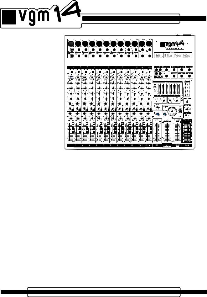
Introduction
Welcome to the Yorkville Sound VGM14, a versatile, compact, low-noise live audio mixer designed for use in small to medium size clubs, churches and corporate events as well as home studios. The VGM14 is suited for use with powered loudspeakers, power amplifiers as well as other types of recording gear.
The Yorkville Sound VGM14 features:
•A simple, soft-knee audio compressor on the mono channels providing a better mix
•Set Level LEDs on channel inputs for easy Channel Gain adjustment
•A switchable hi-impedance guitar input on two channels
•48-volt phantom power
•Parametric EQ on the mono channels, 4 band EQ on the stereo channels
•Aux bus with a pre/post switch on all channels
•Onboard 24-bit digital effects with 16 adjustable presets
•Audio compression on the internal effects for cleaner digital effects
•Assignable stereo graphic equalizer
•Break switch mutes all input channels
•All input channels feature their own Mute switch
•All input channels feature a Solo function
•Clip LEDs on all critical signal inputs and outputs
•Set Level LED on the Media Output for optimum USB audio level
•Balanced XLR and T.R.S. phone jack outputs
•Zone/Sub adjustable output
•USB audio input and output
•Universal switching power supply operates on 100 to 240 volts AC
•LED lamp connector
1
Realizing that some VGM14 users may be unfamiliar with certain features, this manual will help to explain the various functions through describing specific functions for by user.
For general information about mixing and other facets of sound-reinforcement check out our P.A. User Guide available on the internet... (http://www.yorkville.com).
1/4-inch Phone Plug
1/4-inch T.R.S. Phone Plug
XLR Plug
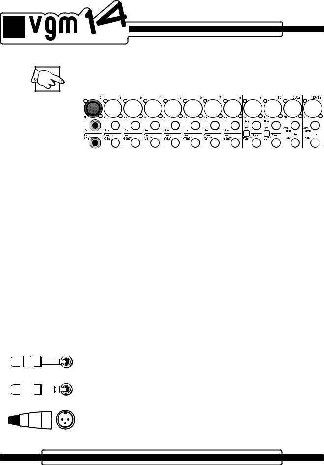
Input Channel Features
1. Microphone Inputs
All mono and stereo input channels have microphone XLR inputs.These microphone inputs are balanced for maximum noise suppression. The VGM14 active input circuitry accepts microphones with impedances ranging from 50 ohms through 10,000* ohms. All low impedance microphones are compatible. Phantom power (covered in the Rear Panel section of this manual) is available on all Mic inputs when activated. This feature is for condenser microphones but dynamic microphones can also connect simultaneously without problems.
*Although it would be customary to plug high impedance microphones into the Line jacks, most of them will also work in the Mic inputs, provided the microphone’s built-in XLR connections are wired with the audio signal on pin 2 and pin 3 is connected to pin 1.
2. Balanced Line Inputs
Mono line-level sources, such as guitar amplifier line-level outputs, keyboards, and hiimpedance microphones connect to the mono or stereo channels through the line input jacks. The Left and Right Line inputs on the stereo channels are wired internally so that a single (mono) signal connected to the L/Mono input will also be patched over to the Right input (as long as a phone plug is not plugged into the Right jack). This sim - plifies connecting a mono source, should the need arise (in the situation where all the mono channels are taken).
You can connect stereo audio sources such as a CD-player, MP3 player or tape deck to the Line inputs on the stereo channels. Use RCA to phone plug adapters to connect RCA cables to the Line inputs. It is possible to connect stereo sources to the mono channels; however you will need to plug the Left and Right signals into separate channels to avoid the risk of inter-modulation distortion. The inter-modulation distortion may be caused by using a “Y” connector to combine the left and right signals into a single Line jack. If you connect a stereo source to two mono channels don’t forget to adjust the Pan controls so that one is set to L(eft) and the other is set to R(ight). this will make sure that the left and right music signals remain separate.
Channels 9 and 10 have high impedance, unbalanced ¼-inch inputs. They’re opti - mized for instruments such as electric or acoustic guitars. To change to a high impedance input, push the appropriate Hi-Z switch.
The balanced connector wiring is:
Tip (or XLR pin 2) = hot, in phase;
Ring (or XLR pin 3) = hot, reverse phase; Sleeve (or XLR pin 1) = ground
You can connect an unbalanced source to the Line inputs with a standard unbalanced shielded patch cable without any adverse affects.
2

Input Wiring tips:
1.For all input connectivity use shielded wire only. Cables with a foil shield or a highdensity braid are best.
2.When changing input connections, turn down the level controls on the mixer to eliminate pops and thumps out of the loudspeakers.
3.Keep input connection cables as short as possible to minimize noise and hum.
A slight modification to a balanced patch cable will help achieve noise cancellation when connecting the VGM14 to an unbalanced unit. Simply modify one end of a balanced patch cord and de-solder the wire from the ring tab, then resolder the wire to the shield tab making sure that it does not touch anything else. Now re-assemble the plug and mark it with some tape for future reference. This will be the end that you plug into the unbalanced music source (this will also work with an RCA connector).
For best performance when connecting turntables, a phono RIAA pre-amplifier must be used to connect to the VGM14 inputs.
Connecting signals to both types of inputs on any one channel (Mic and Line In) is NOT recommended. To do so may change the gain of the input circuit.
3. Insert Jacks
These are 1/4-inch Tip-Ring-Sleeve (TRS) connectors, combining send and return functions for patching outboard signal processing directly into a channel. A suitable patch cable for this function (e.g. Yorkville model PC-6iSPH) would consist of a single TRS (stereo) 1/4-inch plug and two lengths of shielded cable with a common ground branching to two regular (mono) 1/4-inch plugs. The TRS wiring is tip/send, ring/return and sleeve/ ground. Since the PC-6iSPH comes with the leads marked Tip and Ring, connect the Tip plug to the input of the signal processor (EQ, compressor, echo, etc.); connect the Ring plug to the processor’s output. The TRS plug would go into the Insert jack.
The send function is post-Gain and post-HPF (high-pass-filter). Alternately, the Insert jack may be used to send an audio signal from that channel to a powered monitor (some people want to hear only themselves). Simply use an unbalanced shielded patch cable – in this one case, a balanced cable will not work. Be sure to insert the plug only to the first “click” when using the Insert as a channel send, otherwise the signal is interrupted and the channel will not work. If this happens, you have inserted the plug too far. Simply pull the plug out gently to the first stop.
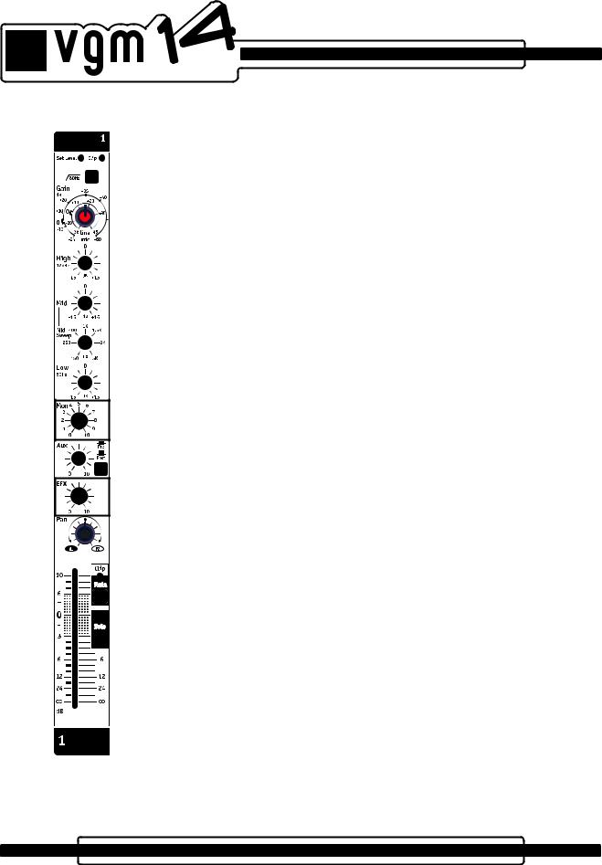
4. Gain Control
The VGM14 features active channel input circuitry with exceptionally high audio headroom.
The Gain control adjusts the input gain level to match it with the input audio signal level. There are two gradation circles on the gain controls, the outer one (-24 dB to +60 dB) is the gain for the Mic Input, the inner one (-36 dB to +45 dB) is for the Line input. This control has a wide range of 84 dB and is very useful to the user when setting the gain.
Here is a quick way to ensure that the Gain is adjusted correctly for the highest headroom and lowest noise during a sound check. First turn the Channel Fader to the infinity symbol. With a music source playing into the mixer’s channel, turn the Gain control clockwise until the Set Level LED begins to flash. Having the Set Level LED flashing shows you that you have the optimum gain setting for the music level on that channel input. Having the Set Level LED remain on continuously indicates that you should turn down the Gain control until the Set Level LED is flashing. Having the Set Level LED remain on continuously indicates that the input audio compressor is active. Now turn up the Channel Fader to the desired audio level for the overall music mix. How to use the input audio compressor is explained below.
The VGM14’s Clip LED will turn on at 3 dB below the onset of actual clipping. It’s okay to have this LED flash occasionally during music peaks. You’ll find that this, or any audio system, performs with less distortion (and less noise) when the gain controls are set properly.
3
Mono
Channel
5. Input Channel Audio Compressor
Each of the mono input channels of the VGM14 (channels 1-10) has an internal dualslope soft-knee audio compressor. The VGM14’s compression function is suitable for keyboards, percussive sources, and vocals.
A compressor reduces the dynamic range of the music providing a more constant level. Like having a sound engineer dynamically adjusting the gain of each channel for the optimum audio level.
The VGM14 compressor works automatically in the background. It can reduce clipping of the audio signal during loud passages in the music which provides a tighter sound typically heard in audio recordings. You can adjust how much compression you want with the input channel Gain control.
Here is how to use the compressor: in automatic mode, set the Gain level so that the Set Level LED is just blinking to the music. The compressor will remain off until
someone yells into the microphone or there is a loud percussive sound, then the compressor will lower the gain, reducing the possibility of clipping. To adjust for little to no compression, have the music source playing into the input channel. Turn up the input channel Gain control to the point where the Set Level LED is just blinking with the music. At this point the full dynamic range of the music source will be experienced. Continuing to turn the input channel Gain control clockwise, the music will get louder. To maintain the same audio level turn down the Channel Fader for the channel being adjusted. The further the input channel Gain control is turned clockwise, or the louder the music source becomes, the greater the compression will be experienced.
If the Clip LED blinks occasionally then the maximum amount of compression has been reached. If the Clip LED remains on for longer periods, turn down the input Gain level until the Clip LED blinks occasionally.
6. High Pass Filter Button
Situated at the top of the channel strip, this switch activates a High-Pass Filter (a bass roll-off of 18 dB per octave below 80 Hz). The HPF (High-Pass Filter) is useful for controlling unwanted low-frequency spillover picked up by microphones located too close to the bass drum, bass amp or the keyboard amp. It is also effective in optimizing acoustic guitar pickups that sound boomy from the guitar body resonance (the lowest note on a concerttuned guitar is 81.2 Hz, so you are not losing anything by rolling off the input response below 80 Hz). Additionally, the HPF works to reduce breath pops and wind noise from vocal microphones. Any microphone, or pickup, connected to a source that does not go below 80 Hz should have the HPF activated. This includes most wind instruments, most male voices, nearly all female voices and all drum microphones except for the kick-drum.
Why roll off the bass on these channels? …Because you will get better sound clarity and improve the system’s gain before feedback.
7. Mono Channel EQ
The VGM14’s mono channels feature 3-band Equalization consisting of Low and High shelving filters and a sweepable Mid control. The Low and High shelving filters are preconfigured at 80 Hz and 12 kHz with a control range of +/-15dB. The sweepable Mid EQ has a selectable frequency range from 150Hz to 5 kHz, with a control range of +/-15dB. The tone control frequencies were carefully chosen to help achieve the best quality of sound.
It’s best to set the channel EQ during a sound check. It is best to minimize the amount of EQ “boost” or “cut” you add to the audio. +/-15dB represents a considerable level change.
For vocals turning the Low control counterclockwise will reduce the boominess of male voices. For male or female vocals it will also “clean up” the mix, as this channel will reduce the bass sound from instruments heard by this microphone.
The Mid control is a very powerful because adjusting it affects the tone of any music source. Including the sweep frequency control makes the mid EQ even more useful albeit more complicated. A good rule-of-thumb to follow is, use as little boost and cut as possible to the signal. If a vocal, or instrument, sounds “honky” you would typically “cut” (or turn the Mid control counter clockwise) in order to reduce the selected mid frequency. You
4

might also try to dial the boost control into the 2 o’clock position and rotate the frequency control from 150 Hz to 5 kHz which might help you to find the annoying frequency in the audio source. Then, with the frequency control set to that particular annoying frequency, slowly turn the Mid level control down to the (-) side of “0” to obtain the best sound.
One possible cure for a bad feedback problem is to use the sweepable Mid EQ to attenuate only the frequency that is causing the feedback. That way, fewer innocent frequencies are affected. Simply set the Mid level control to the 10 o’clock position then slowly rotate the sweep frequency control from 150 Hz to 5 kHz until the feedback stops. Now turn the Mid level control up slightly to normalize the frequency response as much as possible without feedback.
Cymbals can sound hotter, or an instrument can sound brighter, when you boost the High EQ control. Be cautious and only add a little boost. Too much boost can be the cause of the dreaded, squealing feedback. Cutting the High EQ setting can reduce hiss coming from some audio sources, and may make some bass toned instruments sound warmer.
Although frequency sweep controls have graced the channel EQs of recording mixers for many years, they’re usually found on more upscale P.A. mixers used for live applications. As a result, many P.A. users, even veterans, are a little unfamiliar with their function. The Sweep control determines the range of frequencies that are affected by the Mid cut/boost, it moves (or sweeps) the Mid control’s peak (or notch) in response up to several thousand Hertz, or down to below 100 Hz. As a result, it may have quite a noticeable effect on the sound quality, especially since the MID cut or boost will be interacting with whatever cuts (or boosts) you may have set with the Low or High EQ controls.
The Sweep control can shape the sound similar to the way a typical EQ does but more precise since you have control of the frequency being affected. It is worthwhile to spend some time becoming acquainted with how it works.
Be cautious, if you boost the Low tone control and then add a Mid boost at 150 Hz, this would create a situation of overlapping boosted frequencies. This can potentially damage your woofers due to excessive low frequency content. Similarly, watch out for your tweeters/horns if you set the Mid frequency at 5 kHz at then turn up the High tone control.
As music plays through a channel on the mixer and speakers, adjust that channel’s Mid tone control, first boosting, then cutting, and then sweeping back and forth. (Note: if the Mid control is set to the center position, the Sweep control will have no effect at all). Repeat the process with the channel’s Low and High EQ controls at various settings (remember to keep the volume at a safe level).
Note: Setting the Mid Sweep frequency to 2.5 kHz is the same frequency of the fixed Mid controls on our other mixers.
Together, Mid and Sweep controls can be used to accomplish a variety of tasks from combating feedback to improving the way things sound through the P.A. or on recording.
Here are some of those tasks and settings:
Note: These are approximate settings only. Use them as a starting point and “tune around” them.
•Killing feedback? Set Mid at -6 dB and slowly rotate Sweep until the feedback stops. If needed cut the MID further.
•Bonky sounding snare drum? -6 dB @ 200 Hz (roll off Low EQ -6 dB)
•Boomy bass drum? -6 dB @ 300 Hz (Low EQ @ +6 dB and High EQ @ +3 dB)
•Washy sounding cymbals? -9 dB @ 300 Hz (roll off Low EQ -15 dB)
•Excessive hiss from guitar, bass or keyboard amp? +3 dB @ 5 kHz (High EQ rolled off -9 dB)
•Fading vocal range (notes too low for singer)? +3 dB @ 80 Hz (Low EQ rolled off -6 dB)
•Puffing on harmonica mic? -9 dB @ 80Hz (Low EQ rolled off -12 dB)
•Rack Toms? -3 dB @ 400 Hz
•Floor tom? -6 dB @ 200 Hz
5
Generally speaking, you’ll probably end up with the Mid control in cut mode for most problem solving uses of the Sweep control. In any case you will learn to use this feature judiciously. The best P.A. EQ setting is the one with the least adjustment, but when you need to solve a problem it is good to know how to use the tools.
8. Stereo Channel EQ
The VGM14’s stereo channels feature 4-band Equalization with a control range of +/-15 dB. The High EQ is shelving at 12.5 kHz, Low EQ shelves at 80 Hz, the High Mid EQ is centered at 3 kHz, and the Low Mid EQ is centered at 400 Hz. The 4-band Equalization was carefully selected to help achieve the best quality of sound for line level and stereo sources.
As with the Mono Channel EQ it is best to set the channel EQ during a sound check. It is best to minimize the amount of EQ “boost” or “cut” you add to the audio. +/-15 dB represents a considerable level change.
9. Mon (Monitor)
The Mon (Monitor) is the audio signal sent to the stage monitors for the musicians. This control adjusts the level of signal from each channel to the master section’s Mon fader. The signal for the channel’s Mon control is independent of the Channel Fader (pre-fader); adjusting the Channel Fader will not affect your monitor mix.
Note: When feedback occurs, the cause is often the audio signals from the stage monitors feeding back to the microphones. When this happens, the first thing to do is turn down the master section’s MON fader, this will make sure that the monitors (and not the main P.A.) is the cause of the feedback. If the cause is the monitors follow these steps:
A.Turn up the master section’s Mon fader until feedback is just starting.
B. Now turn down each channel’s Mon control just a little, and then return the control back to the original position. This will help you discover which control reduced the feedback the most.
C. With that information, reduce the level on that particular control to the point of no feedback. By using the Mon control, you will most-likely eliminate the feedback without affecting that channel’s level through the main P.A.
With the VGM14’s independent monitor mix, it can be beneficial to assign the internal graphic equalizer to the Mon output and use the graphic equalizer to help control feedback.
10. Aux (Auxiliary)
The Aux (Auxiliary) feature can be used to send audio for use as a 2nd Mon (Monitor), a 2nd EFX, a additional subwoofer signal, or it can be used for a separate mix to be sent to another piece of outboard gear. The switch, located beside the Aux level control, selects either a pre-channel fader signal or a post-channel fader signal.
• In the Pre position, the audio signal is sent to the Aux mix before the signal is sent to the channel fader. Since the channel fader does not affect the level of this signal you can use the Aux control as a 2nd Monitor mix.
• In the Post position, the audio signal is sent to the Aux mix after the channel fader, this means the channel fader‘s level affects the signal set to the Aux mix. This behavior allows the Aux control ideal for use as a 2nd EFX mix, a separate Subwoofer signal, or for use as a separate audio signal for a zone or other purpose.
Note: If used as a Subwoofer buss, the Aux control allows you to specify specific channels, such as the bass instrument channels, optimizing a clean well defined bass sound.
|
|
|
|
|
|
|
11. Digital Effects (EFX) |
|
|
|
|
|
|
|
|
|
|
|
|
|
|
|
The channel EFX controls adjust the level of signal from each channel to the EFX Send |
|
|
|
|
|
|
|
control. The signal sent to the EFX control comes from the Channel Fader (post-fader). |
|
|
|
|
|
|
|
Adjusting the Channel Fader will change the level of the dry signal and the EFX signal. |
|
Stereo |
The signal from the EFX Send control continues to the internal effects generator and to |
|||||
|
the EFX Send jack, for use with an external effects unit. |
||||||
Channel |
|
||||||
6
Alternatively, if you don’t require any effects, the signal from the EFX Send jack can be connected to the input of an additional monitor system or another amp/speaker system (using a standard balanced patch cord). In this case, the EFX controls act as send controls achieving a semi-separate mix. Remember that the Channel Fader level control also affects this signal (it’s a post-fader signal).
12. Pan Control (Mono Channels)
The Pan control routes the channel’s signal after the channel’s fader (post-fader) to the left and right Main buss channels. Signal levels are compensated at the Pan controls L&R extremes so that ‘panning’ during a performance will result in a minimal sound level change in the center-field audience areas.
In audio terminology, a buss is a mix-down channel where all the signals from the input channels are blended into one signal. The VGM14 has 5 busses: MAIN, MONITOR, EFFECTS, AUX (pre and post), and MEDIA OUT.
13. Balance Control (Stereo Channels)
This controls the stereo channel signal routing to the Main Fader. Similar to the Pan Control, the Balance Control can shift the center image between the left and right Main buss channels.
14. Mute Switch
Each channel’s Mute Switch defeats that particular channel’s left, right, and all of its
‘sends’ signals. The Mute function is a timesaving feature that enables you to mute channels without turning down the Channel Fader that's been set for performance.
It is good practice to mute all unused channels during a performance, open microphones increase the possibility of feedback and can make an audio mix sound muddy.
15. Clip/Mute LED
The Clip LED illuminates at 3 dB below the channel’s actual clipping level; with the Clip LED threshold set below actual clipping level, it’s allowable to have occasional cliplight activity without worrying about distortion. As a result, you may use the Clip LED to help adjust for proper gain with the Channel Fader control. When the Mute switch is depressed, the Clip LED will illuminate at half–brightness to indicate the mute condition, it still flickers to indicate clipping.
16. PFL Solo Switch and LED
Each channel features a PFL Solo switch (pre-fader listen) and Solo LED. When the Solo switch is pressed and the Solo LED illuminates, the audio before the fader (pre-fader) of that channel is sent to the VU-meter and the headphones. The level shown on the VU meter is independent of the Phones level control. The VU-meter will display the audio level after the channel tone controls
but before the mute switch; this helps to verify the channel audio level. You should set the level for 0dB on the VU-meter. The Solo audio can be heard in the Phones to preview the audio signal before it’s mixed with the other channels. With the channel mute switch engaged, you can “cue up” audio sources before you add them to the main mix.
7
Loading...