


OWNER’S MANUAL
MANUEL DE L’UTILISATEUR
o-mp10ds-2v0.qxd 09.29.00 jb

IMPORTANT SAFETY INSTRUCTIONS
INSTRUCTIONS PERTAINING TO A RISK |
INSTRUCTIONS RELATIVES AU RISQUE |
OF FIRE, ELECTRIC SHOCK, |
DE FEU, CHOC ÉLECTRIQUE, OU |
OR INJURY TO PERSONS. |
BLESSURES AUX PERSONNES. |
CAUTION:
TO REDUCE THE RISK OF ELECTRIC SHOCK, DO
NOT REMOVE COVER (OR BACK).
NO USER SERVICEABLE PARTS INSIDE.
REFER SERVICING TO QUALIFIED
SERVICE PERSONNEL.
Read Instructions:
The Owner’s Manual should be read and understood before operation of your unit. Please, save these instructions for future reference.
Packaging:
Keep the box and packaging materials, in case the unit needs to be returned for service.
Warning:
When using electric products, basic precautions should always be followed, including the following:
Power Sources:
Your unit should be connected to a power source only of the voltage specified in the owners manual or as marked on the unit. This unit has a polarized plug. Do not use with an extension cord or receptacle unless the plug can be fully inserted. Precautions should be taken so that the grounding scheme on the unit is not defeated.
Hazards:
Do not place this product on an unstable cart, stand, tripod, bracket or table. The product may fall, causing serious personal injury and serious damage to the product. Use only with cart, stand, tripod, bracket, or table recommended by the manufacturer or sold with the product. Follow the manufacturer’s instructions when installing the product and use mounting accessories recommended by the manufacturer.
The apparatus should not be exposed to dripping or splashing water; no objects filled with liquids should be placed on the apparatus.
Terminals marked with the “lightning bolt” are hazardous live; the external wiring connected to these terminals require installation by an instructed person or the use of ready made leads or cords.
No naked flame sources, such as lighted candles, should be placed on the apparatus.
Power Cord:
The AC supply cord should be routed so that it is unlikely that it will be damaged. If the AC supply cord is damaged DO NOT OPERATE THE UNIT.
Service:
The unit should be serviced only by qualified service personnel.
AVIS:
AFIN DE REDUIRE LES RISQUE DE CHOC ELECTRIQUE, N’ENLEVEZ PAS LE COUVERT (OU LE PANNEAU ARRIERE). NE CONTIENT AUCUNE PIECE REPARABLE PAR L’UTILISATEUR.
CONSULTEZ UN TECHNICIEN QUALIFIE
POUR L’ENTRETIENT.
Veuillez lire le manuel:
Il contient des informations qui devraient êtres comprises avant l’opération de votre appareil. Conservez S.V.P. ces instructions pour consultations ultérieures
Emballage:
Conservez la boite au cas ou l’appareil devait être retourner pour réparation.
Warning:
Attention: Lors de l’utilisation de produits électrique, assurez-vous d’adhérer à des précautions de bases incluant celle qui suivent:
Alimentation:
L’appareil ne doit être branché qu’à une source d’alimentation correspondant au voltage spécifié dans le manuel ou tel qu’indiqué sur l’appareil. Cet appareil est équipé d’une prise d’alimentation polarisée. Ne pas utiliser cet appareil avec un cordon de raccordement à moins qu’il soit possible d’insérer complètement les trois lames. Des précautions doivent êtres prises afin d’eviter que le système de mise à la terre de l’appareil ne soit désengagé.
Hazard:
Ne pas placer cet appareil sur un chariot, un support, un trépied ou une table instables. L’appareil pourrait tomber et blesser quelqu’un ou subir des dommages importants. Utiliser seulement un chariot, un support, un trépied ou une table recommandés par le fabricant ou vendus avec le produit. Suivre les instructions du fabricant pour installer l’appareil et utiliser les accessoires recommandés par le fabricant.
Il convient de ne pas placer sur l’appareil de sources de flammes nues, telles que des bougies allumées.
L’appeil ne doit pas être exposé à des égouttements d’eau ou des éclaboussures et qu’aucun objet rempli de liquide tel que des vases ne doit être placé sur l’appareil.
Les dispositifs marqués d’une symbole “d’éclair” sont des parties dangereuses au toucher et que les câblages extérieurs connectés à ces dispositifs de connection extérieure doivent être effectivés par un opérateur formé ou en utilisant des cordons déjà préparés.
Cordon d’alimentation:
Évitez d’endommager le cordon d’alimentation. N’UTILISEZ PAS L’APPAREIL si le cordon d’alimentation est endommagé.
Service:
Consultez un technicien qualifié pour l’entretien de votre appareil.
SAFE_V4.doc Version 4.0 02/11/99 11:54 AM
MICROMIX
INTRODUCTION
We have coupled our extensive experience in the development and production of powered mixers, (with state of the art, computer assisted design technology) to create the smallest, lightest, and most powerful combination mixer/amplifiers available. We at Yorkville Sound are confident that you will find your new MP10DS to be an efficient and versatile solution to your mixer needs. This manual contains information to help you get the maximum performance from your MP10DS. We hope you’ll take the time to read it.
STEREO POWER AMPLIFIER
The MP10DS features a high-performance stereo power amplifier, which has been designed to operate safely into low overall speaker impedances. Thanks to a dedicated, sonically transparent, limiter circuit that adjusts the output power level to keep the circuitry cool. Multiple speakers may be connected to the amplifier without the amplifier overheating or shutting down. It will simply reduce output power to a safe level. Just make sure the total load does not fall below 4-Ohms.
INPUT CHANNELS
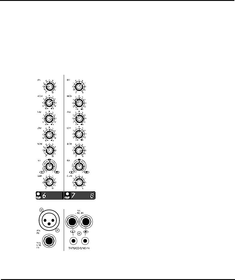
1. MICROPHONE & LINE INPUTS
The MP10DS features standard XLR type Low-impedance MIC IN connectors on the first 6 channels. These microphone inputs are electronically balanced for maximum noise suppression and have characteristics matching all low impedance dynamic microphones. Condenser microphones may also be connected with 24 Volt DC phantom power activated via the back-panel PHANTOM push-button. (Note: condenser and dynamic mics may be used together with the PHANTOM power activated. It will not affect the performance of the dynamic mics). Additionally, there are high-impedance 1/4” BAL LINE IN jacks on all channels. These are electronically balanced line-level inputs, but will accept either balanced or unbalanced input cables from high impedance microphones, guitars, amplifier Line outputs, synthesizers, electric pianos, etc. (Note: when connecting a balanced signal, employ balanced patch cables with a ring/tip/sleeve (stereo) 1/4” plug on the mixer end). Channels 7/8 and
9/10 have Left & Right 1/4” BAL LINE IN jacks plus Left & Right
TAPE/CD/LINE RCA type inputs. Either the 1/4” or RCA type input (not both) may be used to connect a stereo tape deck, CD player or outboard mixer to these channels. A phono preamplifier must be connected to the MP10DS inputs for optimum turntable performance.
Do not connect signals to both types of inputs on any one channel (e.g. the MIC and LINE IN’s on channels 1 to 6 or the 1/4” and RCA type TAPE/CD/LINE IN’s on channels 7/8 and 9/10). To do so will cause improper operation of the input circuit. (Note: you may connect a stereo source to channels 1 through 6 but you must use two channels, one for left and one for right).
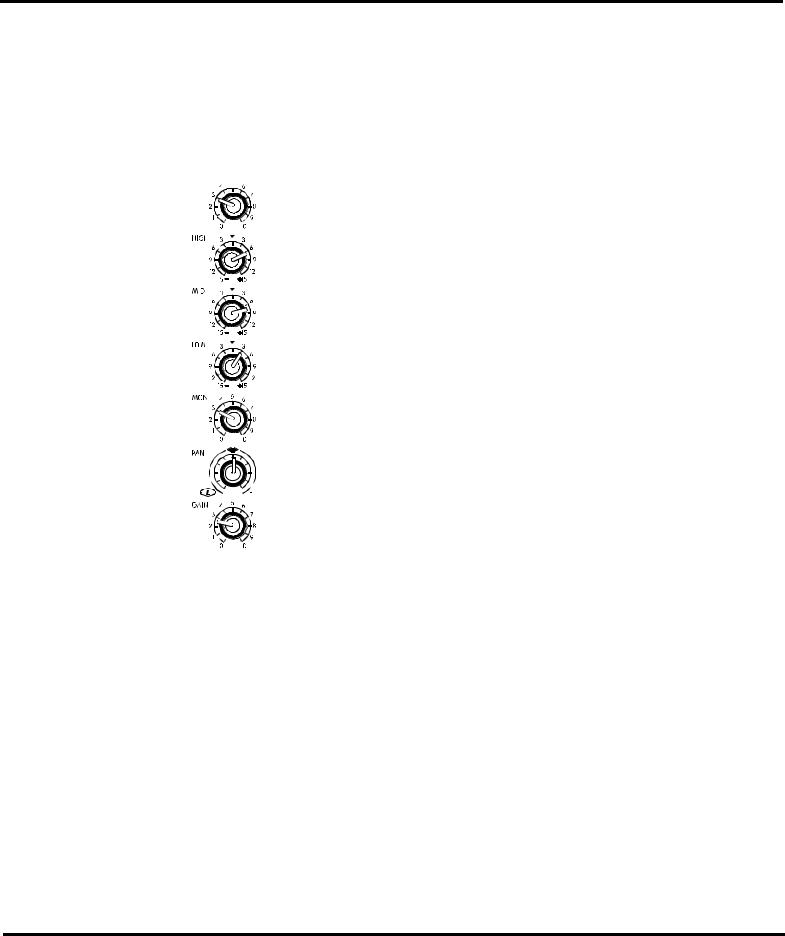
2. CHANNEL GAIN CONTROLS & CLIP LEDS
The GAIN control has a range of 40dB. This adjustment determines both the input sensitivity of the channel and the signal level sent to the MAIN mixing bus*. (The MP10DS channel circuitry does not require separate gain and level controls). The CLIP LED is set to illuminate when the channel’s overall signal level is 3dB below the onset of actual clipping distortion. As a result, small amounts of LED activity are acceptable, however frequent or continuous activity indicates the need to turn down the GAIN control.
In audio terminology, a bus is a mix-down channel where all the signals from the input channels are blended into one signal. The MP10DS has three buses, MAIN, MONITOR and EFFECTS.
3. CHANNEL LOW, MID, & HIGH EQUALIZATION
The MP10DS, LOW, MID & HIGH EQ controls independently adjust the bass, middle and treble frequencies for each channel. Center frequencies have been carefully selected for optimum sonic adjustments and the gain range for each control is plus or minus (+/-) 15dB to provide versatile equalization consistent with the clean simplicity of the MP10DS’ design.
MICROMIX
1
MICROMIX
As with all equalizers, boosts at one or more frequencies increase the channel’s signal level. If the channel is already at a fairly high operating level, this may cause clipping, in which case the CLIP LED will light. Reduce the GAIN setting and/or the EQ boosts if CLIP activity is excessive. (Note: center position reflects a neutral or flat EQ control setting, however lower EQ control settings may be effectively employed to reduce feedback and/or distortion).
4. CHANNEL MON CONTROL
Each channel has a MON (monitor send) control which varies the amount of channel signal being tapped off and sent to the monitor bus in the MP10DS. The MON signal is pre-fader and pre-EQ, in other words it is taken before the GAIN and EQ controls so that the monitor mix can be independent of the main mix. As a result, channel EQ settings do 
 not affect the sound of the monitor signals, nor do the channel GAIN controls
regulate their volume. (Note: with an independent monitor mix, it may be ben-
eficial to connect a graphic equalizer to the MONITOR output for feedback
control).
5. CHANNEL EFX CONTROL
Each channel has an EFX (effects send) control which adjusts the level of the
channel signal being tapped off and sent to the MP10DS, effects bus. This sig-
nal is post-fader and post-EQ, in other words it is affected by both the channel
EQ controls and the channel GAIN control. Normally, the output signal from
the effects bus is internally routed to the DIGITAL EFFECTS PROCESSOR. In
this situation, the EFX control would regulate the intensity of the built-in effects
on that channel’s sound through the main PA system and the RECORD OUT
jacks. In standard operating mode with the built-in effects working, you would
connect a regular on-off footswitch (e.g. Yorkville model IFS-1A) to the EFX
FOOTSWITCH/SEND jack to turn the internal effects on and off. See the sec-
tion EFX FOOTSWITCH/SEND later in this manual for more information.
Alternatively, this signal can be connected to the input of an external stereo
effects unit and returned via channel 7/8 or 9/10. However, if you do not
require any effects at all, the effects bus output signal can be connected to the
input of an additional monitor system or other amp/speaker system via the EFX
FOOTSWITCH/SEND jack using a standard shielded patch cord. In this case,
the EFX controls would act as send controls to achieve a semi-separate mix.


 (Remember that the channel GAIN controls will also affect this signal).
6. CHANNEL PAN & BALANCE CONTROLS
The signal balance of each channel going to the left and right main PA channels
can be adjusted by the PAN control in channels 1 to 6, and by the BALANCE control in channels 7/8 and 9/10. Turning this control counterclockwise towards the L will increase the signal level in the left channel while also reduc-
ing the level in the right channel. Turning the control clockwise towards the R will increase the signal level in the right channel while also reducing the signal level in the left channel. For stereo PA applications, you would leave the PAN and BALANCE controls at center position. This ensures that all audience members throughout the venue hear the same mix of instruments and voices. However, if you are using the MP10DS strictly for recording purposes, you may employ the PAN or BALANCE controls to send channels or stereo-recorded music tracks to the left or right tape tracks by turning them all the way to L or R.
MICROMIX
2
MICROMIX
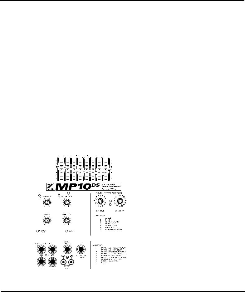
MASTER SECTION
1. MAIN MASTER CONTROL & CLIP LED
The MAIN MASTER control adjusts the overall level of the main mix and the PA volume. Beside this control is a CLIP LED, which indicates high signal levels within the main mixing bus. Reduce the MAIN MASTER or the channel GAIN controls if the MAIN CLIP LED is more than slightly active. (Note: to ensure maximum signal headroom and clarity, operate the mixer with the MAIN MASTER set at 7 or so. This way, you will be running the channel GAIN controls at lower settings, which helps to ensure that the channels do not clip).
2. MONITOR MASTER CONTROL
The overall level of the monitor mix is adjusted with the MONITOR MASTER control. Beside it is a CLIP LED, which indicates high signal levels within this bus. Reduce the MONITOR MASTER or the channel MON levels if the MONITOR CLIP LED is more than slightly active. (Note: as with the MAIN MASTER, keep the MONITOR MASTER at a relatively high setting to ensure maximum clarity).
3. MAIN EFFECTS MASTER CONTROL
The MAIN EFX master control regulates the amount of signal going from the output of the internal DIGITAL EFFECTS PROCESSOR to the MAIN mixing bus where it is mixed with the dry signals direct from the channels. It controls overall effects intensity on the L and R MAIN output signals and RECORD OUT signals and through the main PA speakers.
4. MONITOR EFFECTS MASTER CONTROL
The MONITOR EFX master control regulates the amount of signal going from the output of the internal DIGITAL EFFECTS PROCESSOR to the MONITOR mixing bus where it is mixed with the dry signals directly from the channel MON send controls. It controls the overall effects intensity of the MONITOR LINE OUT signal.
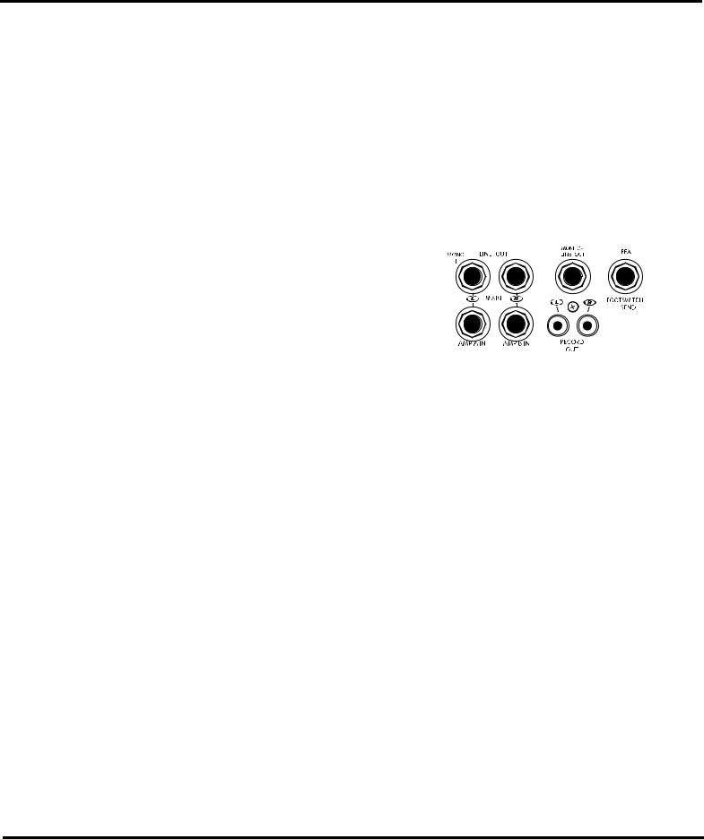
5. MAIN LINE OUT & AMP IN JACKS
These jacks can serve a variety of patching and routing purposes. They are positioned in the signal path after the MP10DS, main graphic equalizer and are therefore regulated by it (i.e. they are post-EQ).
The main bus signals are available at line level (not speaker level, use the SPEAKER outputs on the back panel to drive speakers) from the L & R MAIN output jacks. Taking a signal from these jacks has no effect on the operation of the MP10DS, built-in power amplifier. It is there- 


 fore possible to feed an external power amplifier or even
several, interconnected power amps, with the MAIN out-
put signals while the internal power amplifier is also
functioning (although it is not necessary to have speakers
connected - e.g. if you want to use the unit strictly as a
mixer). If a mono signal is required, possibly to feed a
mono-house PA or another amp/speaker system, use the L
- MONO jack. Mono operation of this jack is converted
to left channel stereo operation as soon as a jack is insert-
ed in the R MAIN output jack.
The AMP A IN and AMP B IN jacks are direct inputs to the built-in power amplifier. They are referred to as A and B rather than left and right simply because, with the MP10DS, versatile design, it is possible to power main PA speakers with one amplifier channel, and monitors with the other. This can be accomplished by running a shielded patch cord from the L- MONO MAIN output to the AMP A IN jack, then another patch cord from the MONITOR output to the AMP B IN jack. An alternative use for the AMP A & B IN jacks is as patching inputs. Because they are switching jacks, when you plug into one, or both of them, you interrupt the internal flow of signals going from the outputs of the Main mixing bus to the inputs of the built-in power amp. This allows you to insert stereo signal control devices such as an élite processor, an additional
MICROMIX
3
MICROMIX
equalizer, or a compressor/limiter into the Main stereo signal path. This is accomplished by connecting two cables from the L & R MAIN outputs to the device’s input jacks and two more cables from the device’s output jacks to the MP10DS, AMP A & B IN jacks.
It is even possible to connect another mixer to the MP10DS, power amplifier via the AMP A & B IN jacks. This slaves the amplifier to that mixer’s signals (i.e. it no longer receives the built-in mixer’s signals), which means that you could use the built-in mixer to do another, totally separate mixing job. For example, you could patch the MP10DS, L & R MAIN outputs to two inputs on another mixer connected to amps driving a PA speaker system while using the A and B amps to power control room speakers.
6. RECORD OUT JACKS
These phono connectors carry the Left & Right pre-EQ (not affected by the MAIN EQ) main mix signals. RECORD OUT signal levels are regulated by the MAIN master. Using phono-to-phono patch cords, connect the RECORD OUT jacks to the Aux. (line-level) inputs on the tape deck.
Actual recording levels would now be adjusted using the tape deck’s record level control/s.
Best results for recording will be achieved with the MAIN master and channel levels set fairly high. If you need to record while the MP10DS is
operating in a PA situation and set at lower levels, perhaps in a church, you can have a technician
make up two short **padded patch cables as specified below. These would be connected between the L & R MAIN LINE OUT jacks and the AMP A &
B IN jacks. They will reduce the amount of signal going to the power amplifier inputs so that the
MAIN master and channel levels can be set high enough to provide adequate RECORD OUT signal
levels without the PA system being too loud.
** To fashion the -20dB padded patch cables, start with two short, shielded patch cords. On each cord, solder a 10k Ohm resistor in series with the tip of the plug to be inserted in a LINE OUT jack, then solder a 2.2k Ohm resistor across the plug to be inserted in an AMP IN jack. It would then be advisable to identify either the LINE OUT or AMP IN plugs on both cords perhaps with tape or a dab of paint on the plug jacket.
7. MONITOR LINE OUT JACK
The monitor bus output signal is available at line level (not speaker level) from the MON OUT jack and would normally be patched to the input of a mono power amplifier, or one channel of a stereo amp driving monitor speakers. Keeping in mind that there is no internal equalization for the monitor mix, you might want to patch a graphic equalizer between the MONITOR OUT jack and the input of your monitor power amplifier to help regulate feedback (see Note below). As mentioned under MAIN OUT & AMP IN JACKS, the monitor mix signal can also be patched to one channel of the internal amplifier. If a main/monitor amplifier configuration is desired, use the LEFT MONO signal from the MAIN OUT jacks to feed one amplifier. The MON OUT signal could be used to feed the remaining amplifier (this is also covered in the previous section).
Note: Patching something between things, in this case, means connecting the MP10DS ’s MONITOR OUT jack to the input of an EQ and the output of the EQ to the input of a monitor power amp
8. EFX FOOTSWITCH/SEND JACK
This jack may be used to connect a standard on/off footswitch for the internal DIGITAL EFFECTS PROCESSOR or alternately as an effects send jack to another effects processor. In this latter function, both devices would be sent signal. In that instance, you could connect the external unit’s left and right outputs to the L & R inputs on channel 7/8 or channel 9/10 (or any of the other channels. Here you would need to keep the GAIN level of that channel fairly low and make sure that its EFX control is turned off on these channels. As another alternative, the EFX FOOTSWITCH/SEND jack may be used to deliver line-level signal to the input of an auxiliary amp/speaker system or a tape deck. Here, the channel EFX controls would act as secondary level controls. Keep in mind, however, this means that the built-in DIGITAL EFFECTS PROCESSOR will be disabled.
MICROMIX
4
 Loading...