

Page 1

User's
CL150
Manual
Clamp-on Tester
クランプテスタ
IM CL150
保証書付
Test Equipment Depot - 800.517.8431 - 99 Washington Street Melrose, MA 02176
TestEquipmentDepot.com
IM CL150
2018.6 11版( KYOU)
Page 2

Contents
■ Precautions for Safety Use of the Instrument ……………………………… i
1. Instrument Layout …………………………………………………………… 1
2. Measurement ………………………………………………………………… 3
2.1 Preparation for Measurement ……………………………………… 3
2.2 Current Measurement ……………………………………………… 3
2.2.1AC Current Measurement (Normal Mode) ………………… 4
2.2.2 Peak Current Measurement (Peak Mode) ………………… 4
2.3 Voltage Measurement ……………………………………………… 5
2.3.1 DC Voltage Measurement …………………………………… 5
2.3.2 AC Voltage Measurement …………………………………… 5
2.4 Resistance Measurement …………………………………………… 6
2.4.1 Resistance Measurement (Normal Mode) ………………… 6
2.4.2 Continuity Check (400Ω range fixed) …………………… 6
3. Other Functions …………………………………………………………… 8
3.1 Sleep Function ……………………………………………………… 8
3.2 Data Hold Function ………………………………………………… 8
3.3 OUTPUT Terminal (For current measurement only) ……………… 9
3.4 Optional Accessories ………………………………………………… 10
4. Battery Replacement ……………………………………………………… 11
5. Specifications ……………………………………………………………… 12
6. Calibration and After-sales Service …………………………………… 15
Page 3

■PrecautionsforSafeUseoftheInstrument
When handling the instrument, ALWAYS observe all of the cautionary notes on
safety given below. Yokogawa M&C Corporation is not at all liable for damage
resulting from misuse of this product by the user that is contrary to these
cautionary notes.
Various symbols are used on the instrument and in this manual to ensure the
product is used safety and to protect operators and property from possible
hazards or damage. The following safety symbols are used where appropriate. Read the explanations carefully and familiarize yourself with the symbols
before reading the text.
The instrument and this manual use the following safety symbols:
Danger!HandlewithCare.
This symbol indicates that the operator must refer to an explana-tion
in the Users Manual in order to avoid the risk of personal injury or
death and/or damage to the instrument.
DoubleInsulation
This symbol indicates double insulation.
ACVoltage/Current
This symbol indicates AC voltage or current.
DCVoltage/Current
This symbol indicates DC voltage or current.
Ground
This symbol indicates ground (earth)
This symbol Indicates that this instrument can clamp on bare conductors when measuring a voltage corresponding to the applicable
Measurement category, which is marked next to this symbol.
WARNING
Indicates that there is a possibility of serious personal injury or loss of life if the
operating procedure is not followed correctly and describes the precau-tions
for avoiding such injury or loss of life.
CAUTION
Indicates that there is a possibility of serious personal injury of damage to the
instrument if the operating procedure is not followed correctly and describes
the precautions for avoiding such injury or damage.
NOTE
Draws attention to information essential for understanding the operation and
features.
IM CL150
i
Page 4

WARNING
●Never make measurement on a circuit above 750V AC or 1000V DC.
● Do not use the instrument in an atmosphere where any flammable or
explosive gas is present.
● Do not attempt to make measurement in the presence of flammable gasses,
fumes, vapor or dust. Otherwise, the use of the instrument may cause
sparking, which can lead to an explosion.
● Avoid using the instrument if it has been exposed to rain or moisture or if
your hands are wet.
●Do not exceed the maximum allowable input of any measurement range.
●Never open the battery compartment cover when making measurement.
● Do not use the instrument if there is any damage to the casing or when the
casing is removed.
● Do not turn the Function Selector switch with plugged in test leads con-
nected to the circuit under test.
● Do not install substitute parts or make any modification to the instrument.
Return the instrument to Yokogawa Meter & Instruments or your distributor
for repair or re-calibration.
● Always switch off the instrument before opening the battery compartment
cover for battery replacement.
● Do not use the test leads that have deteriorated or are detective.
● Check the test leads continuity
WARNING
To avoid damage to the instrument or electric shock!
The restrictions on the maximum voltage level for which the CL150 testers
can be used, depend on the measurement categories specified by the safety
standards. These category specifications are formulated to protect operators
against transient impulse voltage in power lines.
Maximum Allowable Input
Function
A
MEASUREMENT
CATEGORY II
AC 2000A rms
Measuring circuit voltage :
AC 750V rms
MEASUREMENT
CATEGORY III
AC 2000A rms
Measuring circuit voltage :
AC 600V rms
V, V AC 750V rms/DC 1000V
Input terminal-toground voltage
IM CL150
AC 750V rms/DC 1000V
AC 600V rms/DC 600V
ii
Page 5

O (None, Other)
Other circuits that are not directly connected to MEAINS.
Measurement category II (CAT.II)
Local level, appliance, portable equipment etc., with smaller transient over-
voltages than CAT.III.
Measurement category III (CAT.III):
Distribution level, fixed installation, with smaller transient over-voltages than
CAT.IV.
CAUTION
● Always make sure to insert each plug of the test leads fully into the appro-
priate terminal on the instrument.
● Make sure to remove the test leads from the instrument before making
current measurement.
● Be sure to set the Function Selector switch to the "OFF" position after use.
When the instrument will not be in use for a long period of time, Place it in
storage after removing the battery.
● Use a damp cloth and detergent for cleaning the instrument. Do not use
abrasives or solvents.
NOTE
● Radiation immunity affects the accuracy of CL150 testers under the
conditions specified in EN 61000-4-3.
● If equipment generating strong electromagnetic interference is located
nearly, the testers may malfunction.
IM CL150
iii
Page 6

1.InstrumentLayout
(1) Transformer Jaws : Pick up current flowing through the conductor.
(2) Open/Close Lever : Operates the transformer jaws. Press to open the
Transformer Jaws.
(3) Function Selector Switch : Selects ranges. Also used to power the
instrument on.
(4) Data Hold Button : Freezes the display reading. " " is shown on the
display when Data Hold is enabled.
(5) Mode Selector Button : On a AC current (" 400A" or " 2000A" or
the resistance ( ) range. Press the mode button to cycle through the
measurement modes. The instrument is initially set to the normal mode and
can be switched to peak or continuity check mode by means of the mode
button.
IM CL150
1
Page 7

A / V
(ACA/ACV)
Normal
↓
Peak
Display Display
(Resistance/Continuity)
Resistance
↓
Continuity
check
Ω
(6) Button : Reset the measurement in peak mode.
(7) LCD Display : Field effect type of liquid crystal display with maximum
counts of 4000. Function symbols and decimal point are controlled by the
microprocessor based on the selected function and measuring mode.
(8) Terminal Cover : Slides over Hi and Lo Terminals to prevent access to them
when OUTPUT terminal is in use.
(9) OUTPUT Terminal (For "
400A" or " 2000A" range only) : Provides DC
voltage output in proportion to the AC or DC current reading. (See section
3.3, OUTPUT Terminal.) The out-put is connected to a recording device
such as a chart recorder for long hour monitoring. No output is available on
voltage and resistance ranges.
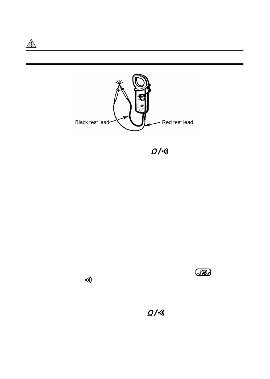
(10) Lo Terminal : Accepts the black test lead for voltage or resistance
measurement.
(11) Hi Terminal : Accepts the red test lead for voltage or resistance meas-
urement.
(12) Safety Hand Strap : Prevents the instrument from slipping off the hand
during use.
(13) Test Leads (Model 98072) : Connected to Lo and Hi terminals for voltage
or resistance measurement.
(14) Barrier: It is a part providing protection against electrical shock and
ensuring the minimum required air and creepage distances.
IM CL150
2
Page 8

2.Measurement
2.1PreparationforMeasurement
CAUTION
● The jaw section is a delicate, precision sensor. Do not subject the jaw to
unreasonably strong shock, vibration, or force when using it.
● If dust gets into the tops of the jaws, remove it immediately. Do not close the
jaws when dust is trapped in its joints as the sensor may break.
● Please check that the function and mode are set to the desired setting
before measurement.
2.2CurrentMeasurement
WARNING
● Do not make measurement on a circuit above 750VDC. This may cause
shock hazard or damage to the instrument or equipment under test.
● Do not make current measurement with the test leads connected to the Hi
and Lo terminals.
● When measuring current is not less than 1000A, make sure to stop meas-
urement within the maximum measuring time shown below. Otherwise,
transformer jaws may heat to cause a fire or deformation of molded parts,
which will degrade insulation.
1000 to 1500A : 15min. 1500 to 2000A : 5min.
● Keep your fingers and hands behind the barrier during measurement.
IM CL150
3
Page 9

2.2.1ACCurrentMeasurement(NormalMode)
(1) Set the Function Selector switch to the " 400A" or " 2000A" position.
"AC" should be shown on the upper left corner of the display.
(2) Press the open/close lever to open the transformer jaws and clamp them
onto the conductor under test, then take the reading on the display. The
most accurate reading will be obtained by keeping the conductor at the
center of the transformer jaws.
NOTE
● During current measurement, keep the transformer jaws fully closed.
Otherwise, accurate measurement cannot be made. The maximum
measurable conductor size is approx. 54.5mm in diameter.
● The transformer jaws may buzz when measuring large current. This has no
effect on the instruments performance or safety.
2.2.2PeakCurrentMeasurement(PeakMode)
(1) Set the Function Selector switch to the "
400A" or " 2000A" position.
(2) Press the button once to enter from the normal mode to the PEAK
mode. " " should be shown on the display.
(3) Press the open/close lever to open the transformer jaws and clamp them
onto the conductor under test. Then, press the button.
(4) The display shows the currents crest value divided by the square root of
two. Therefore, when the current is sinusoidal, the reading equals RMS
value.
(5) To reset the display, press the
button.
(6) After the measurement is over, press the
button to return to the
normal mode.
NOTE
● In the Peak measurement mode, the data hold feature is disabled.
● In the Peak measurement mode, the response time is 10ms.
IM CL150
4
Page 10

2.3VoltageMeasurement
WARNING
Do not make measurement on a circuit above 750V AC or 1000V DC. This
may cause shock hazard or damage to the instrument or equipment under
test.
2.3.1DCVoltageMeasurement
(1) Set the Function Selector switch to the " V " position. "DC" should be shown
on the upper left corner of the display.
(2) Slide the terminal cover to the left to disclose the Hi and Lo terminals. Plug
the red test lead into the Hi terminal and the black test lead into Lo terminal.
(3) Connect the tip of the red and black test leads to the positive (+) and
negative (-) sides of the circuit under test respectively. Take the reading on
the display.
2.3.2ACVoltageMeasurement
(1) Set the Function Selector switch to the " V " position. "AC" should be shown
on the upper left corner of the display.
(2) Slide the terminal cover to the left to disclose the Hi and Lo terminals. Plug
the red test lead into the Hi terminal and the black test lead into Lo terminal.
(3) Connect the tip of the test leads to the circuit under test respectively. Take
the reading on the display.
NOTE
For high sensitivity, there are parts which do not indicate "0".
IM CL150
5
Page 11
2.4ResistanceMeasurement(NormalMode)
WARNING
Never use the instrument on an energized circuit.
2.4.1ResistanceMeasurement(NormalMode)
(1) Set the Function Selector switch to the "
" position. The "Ω" should
be shown on the upper right corner of the display.
(2) Slide the terminal cover to the left to disclose the Hi and Lo terminals. Plug
the red test lead into the Hi terminal and the black test lead into the Lo
terminal. Check that "OL" (over indication) is indicated on the LCD display.
(3) Short the tip of the test leads and check whether the display reads "0".
(4) Connect the tip of the test leads to the circuit under test respectively. Take
the reading on the display.
NOTE
When shorting the tip of the test leads, the display may read a very small
resistance instead of "0". This is the resistance of the test leads on the display.
2.4.2ContinuityCheck(400Ωrangefixed)
The continuity check mode is enabled by pressing the
resistance range. "
" and Ω is indicated on the display to show the
button on
instrument in the continuity check mode. The buzzer beeps, if the resistance
under test is 50 Ω or less.
(1) Set the Function Selector switch to the "
" position.
(2) Slide the terminal cover to the left to disclose the Hi and Lo terminals. Plug
the red test lead into the Hi terminal and the black test lead into the Lo
terminal. Check that "OL" (over indication) is indicated on the LCD display.
IM CL150
6
Page 12

(3) Press the
continuity check mode. "
button once to enter from the normal mode to the
" should be indicated on the display.
(4) Short the tip of the test leads and check whether the display reads "0".
(5) Connect the tip of the test leads to the circuit under test. If the resistance is
50 Ω or less, the buzzer beeps.
NOTE
When shorting the tip of the test leads, the display may read a very small
resistance instead of "0". This is the resistance of the test leads on the display.
IM CL150
7
Page 13

3.OtherFunctions
3.1SleepFunction
This is a function to prevent the instrument from being left powered on in
order to conserve battery life. This function causes the instrument to enter the
Sleep (powered-down) mode about 10 minutes after the last switch or button
operation.
To exit the Sleep mode, press the Data hold,
turn the Function Selector switch back to "OFF", then to any other position, or
press any button.
The current is consumed a little in the Sleep mode.
HowtoExittheSleepMode
Turn the Function Selector switch from "OFF" to another position with the data
hold function button pressed. Then, "P.OFF" is shown on the display. This
disables the sleep function and enables continuous use of the instru-ment.
NOTE
● Connecting the plug to the OUTPUT terminal disables the Sleep function.
The function is enabled on removing the plug from the terminal.
● The Sleep function is disabled in the PEAK measurement mode.
3.2DataHoldFunction
This is a function used to freeze the measured value on the display. Press the
Data Hold button to freeze the reading. The reading will be held regardless of
subsequent variation in input. "
display while the instrument is in the Data Hold mode.
To exit the Data Hold mode, press the Data Hold button again.
" is shown on the upper right corner of the
button or button or
NOTE
● The Data hold function is disabled in the peak measurement mode on the
AC current range.
● When the Sleep function is activated, the Data hold mode turns to the
normal mode.
IM CL150
8
Page 14

3.3OUTPUTTerminal(Forcurrentrangesonly)
WARNING
● Never use the instrument on a circuit above 750VAC or 1000VDC. This may
cause electrical shock hazard and damage to the instrument or the circuit
under test.
● Never apply voltage to the OUTPUT terminal.
Only on the " 400A" or " 2000A" range, DC voltage proportional to the input
current is output from the OUTPUT terminal.
(1) Attach the output plug cable (sold separately : 98076 or 98077) to a
connection lead so that the output voltage can be connected to a recording
device such as a chart recorder.
(2) lide the terminal cover to the right to disclose the OUTPUT terminal and
insert the output plug into the terminal. Make connection to the recording
device.
(3) Set the Function Selector switch to the " 400A" or " 2000A" position and
follow appropriate measurement instructions.
NOTE
● Output voltage is 1mV/A on the " 400A" range and 0.1mV/A on the
" 2000A" range. Set an appropriate input sensitivity on the recorder.
● The peak hold function does not apply to the recorder output even if the
instrument is in the peak hold mode.
● For long term measurement, disable the sleep function.
IM CL150
9
Page 15

3.4OptionalAccessories
Clamp Adapter Model 99025 (For AC current measurement only)
The clamp adapter (99025) has been discontinued.
The clamp adapter (99025) is designed to increase the measuring capability of
a clamp meter. With the use of the Clamp Adapter, you can not only extend
current range over 3000A, but also clamp on a large bus-bar or conductor.
(1) Set the Function Selector switch to the "
A " position.
(2) As shown in the figure below, clamp Model CL150 onto the pickup coil of
Model 99025.
(3) Clamp Model 99025 onto the bus-bar or conductor under test.
(4) Take the reading on Model CL150 and multiply it by 10.
IM CL150
10
Page 16

4.BatteryReplacement
WARNING
To avoid electric shock hazard, make sure to set the Function Selector switch
to "OFF" and remove the test leads from the instrument before trying to
replace battery.
CAUTION
● Do not mix new and old batteries.
● Make sure to install battery in correct polarity as indicated in battery
compartment.
If the battery voltage becomes too low for the instrument to operate normally,
"
battery is completely exhausted, the display blanks without " " shown.
(1) Set the Function Selector switch to the "OFF" position.
(2) Unscrew and remove the battery compartment on the bottom of the
(3) Replace the battery observing correct polarity. Use two new R6P batter-ies.
(4)Re-place and screw the battery compartment cover.
" is shown on the display. Then, replace the battery. Note that when the
instrument.
IM CL150
11
Page 17

5.Specifications
■ Instrument Specifications
● Measuring Ranges and Accuracy (at 23 ±5℃ , 45 to 75% relative humidity)
AC Current
Ranges
400A 0 to 400.0A 0.1A
2000A
AC Voltage ( V) Auto-ranging
Ranges Measuring range Resolution Accuracy
40V 0 to 40.00V 0.01V
400V 15.0 to 400.0V 0.1V
750V 150 to 750V 1V
Initially set to the 40V range. Input impedance is about 1MΩ.
DC Voltage ( V) Auto-ranging
Ranges Measuring range Resolution Accuracy
40V 0 to ± 40.00V 0.01V
1000V 150 to ± 1000V 1V
Initially set to the 40V range. Input impedance is about 1MΩ.
400A, 2000A
Measuring
range
0 to 1000A
1000 to 1500A 15min.
1500 to 2000A ±3.0% rdg (50/60Hz) 5min.
Resolu-
tion
1A
Accuracy (frequency range)
± 1.0% rdg ± 3dgt (50/60Hz)
± 2.0% rdg ± 3dgt (40 to 1kHz)
± 1.0% rdg ± 3dgt (50/60Hz)
± 3.0% rdg ± 3dgt (40 to 1kHz)
± 1.0% rdg ± 2dgt (50/60Hz)
± 1.5% rdg ± 3dgt (40 to 1kHz)
± 1.0% rdg ± 2dgt400V 15.0 to ± 400.0V 0.1V
Maximum
Measure-
ment Time
Continuous
Resistance (Auto-ranging)
Ranges Measuring range Resolution Accuracy
400Ω 0 to 400.0Ω 0.1Ω
4kΩ 0.15 to 4.000kΩ 1Ω
40kΩ 1.50 to ±40.00kΩ 10Ω
400kΩ 15.0 to ±400.0kΩ 100Ω
Initially set to the 400Ω range. In the continuity check mode, fixed to the 400Ω
range and when the reading is not more than . 50 ±35Ω, the buzzer beeps.
IM CL150
12
± 1.5% rdg ± 2dgt
Page 18

OUTPUT (AC Current Ranges)
DC Output : 100.0mV per 1000 counts (Output impedance : about 10kΩ)
Ranges Measuring range Accuracy (Frequency Range)
400A 0 to 400.0mV/0 to 400A
2000A
0 to 150.0mV/0 to 1500A
150.0 to 200.0mV/1500 to 2000A ± 3.5% rdg (50/60Hz)
± 1.5% rdg ± 0.5mV (50/60Hz)
± 2.5% rdg ± 0.5mV (40 to 1kHz)
± 1.5% rdg ± 0.5mV (50/60Hz)
± 3.5% rdg ± 0.5mV (40 to 1kHz)
■ GeneralSpecifications
● Operating System : Dual integration
● Measurement Function : AC current, DC current, AC voltage, resistance,
continuity check
● Display : Liquid crystal display with maximum counts of 4000
● Overrange Indication : "OL" is shown on the display
● Response Time : Approx. 2 seconds.
● Temperature and Humidity for Guaranteed Accuracy : 23℃ ±5℃ , relative
humidity 45 to 75% without condensation
● Operating Temperature and Humidity : 0 to 40℃ , relative humidity up to
85% without condensation
● Storage Temperature and Humidity : -20 to 60℃ , relative humidity up to
85% without condensation
● Effect of conductor position : Within ±2.0%rdg, ±3dgt to a 10 mm-dia
conductor, at every part inside the jaws
● Effect of external magnetic field : 1A or less in AC or DC magnetic field of
400 A/m
● Power Source : Two R6P 1.5V battery
● Battery Life : Approx. 150 hours (continuity)
● Current Consumption : Approx. 5mA max. (Sleep function : Approx. 20μA)
● Sleep function : Automatically powered down in Approx. 10 minutes after the
last switch operation
● Withstanding Voltage : 6300V AC, 50/60Hz for 5 sec. between electrical
circuit and housing case or metal part of the jaws
● Insulation Resistance : 10MΩ or greater at 1000V between electrical circuit
and housing case or metal part of the jaws
● Conductor Size : Approx. 54.5mm diameter max.
● Dimensions : Approx.105(W) x 247(H) x 49(D) mm
● Weight : Approx. 470g (with batteries)
IM CL150
13
Page 19

● Safety Standard: EN 61010-1, EN 61010-2-033
EN 61010-031, EN 61010-2-032
AC/DC 600V CAT III, AC/DC 1000V CAT II,
Pollution degree2, indoor use, altitude 2000m or less
● EMC Standard : EN 61326-1, EN 61326-2-1
● Radiation immunity : EN 61000-4-3
● Environmental standard : EN 50581
● Accessories : Test leads Model 98072 ………… 1set
R6P batteries
Carrying case Model 93034
Users Manual ……………………… 1
● Optional Accessories : Output cable Model 98076
Output cable (for terminal screw) Model 98077
……………………… 2
…… 1
6.CalibrationandAfter-salesService
Should any failure occur while you are using the tester, follow the instructions
given below. If the tester still fails to operate correctly and needs repair, contact
the vendor from whom you purchased the instrument or the nearest Yokogawa
Meters & Instruments sales office.
● Turn off the POWER switch once, then turn it back on again.
● If the tester does not turn on, replace the battery with a new one.
Calibration
It is recommended that the instrument be calibrated once every year.
IM CL150
14
Page 20
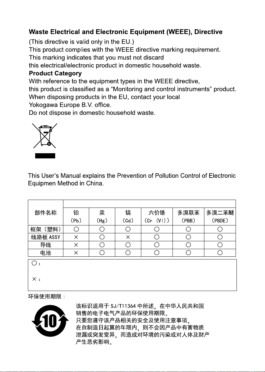
This manual is valid only in China.
产品中有害物质的名称及含量
有害物质
表示该有害物质在该部件所有均质材料中的含量均在GB/T 26572
规定的限量要求以下。
表示该有害物质至少在该部件的某一均质材料中的含量超出GB/T 26572
规定的限量要求。
IM CL150
15
Page 21

 Loading...