

Page 1

User’s
Manual
30-CH Fast Digital
Thermometer Module
Yokogawa Electric Corporation
IM 707231-01E
1st Edition
Page 2

Foreword
Notes
Thank you for purchasing the WE7231 30-CH Fast Digital Thermometer Module, a PCbased measurement instrument for the WE7000.
This user’s manual contains useful information about the functions and operating
procedures of the WE7231 as well as precautions that should be observed during use.
This manual is written with the assumption that you will be using the WE7000 Control
Software that is included with the measuring station.
For general information about the WE7000, (primarily the operations of the measuring
station, the optical interface module, the optical interface card, and the WE7000 Control
Software) see the WE7000 User’s Manual (IM 707001-01E).
Manual Title Manual No.
WE7000 User’s Manual IM707001-01E
To ensure proper use of the instrument, please read this manual thoroughly before
beginning operation.
After reading the manual, keep it in a convenient location for quick reference in the event
a question arises.
• This manual was written for version 4.2.0.0 of the WE7000 Control Software and
module firmware version 3.05. The operating procedures and screen contents
described in this manual may differ from those in other versions of the software.
• The contents of this manual are subject to change without prior notice as a result of
improvements in the instrument’s performance and functions.
• Every effort has been made in the preparation of this manual to ensure the accuracy
of its contents. However, should you have any questions or find any errors, please
contact your nearest YOKOGAWA representative listed on the back cover of this
manual.
• Copying or reproduction of all or any part of the contents of this manual without the
permission of Yokogawa Electric Corporation is strictly prohibited.
Trademarks
• Microsoft, Windows, and Windows NT are trademarks or registered trademarks of
Microsoft Corporation in the United States and/or other countries.
• Adobe and Adobe Acrobat are trademarks of Adobe Systems incorporated.
• All other company and product names used in this manual are trademarks or
registered trademarks of their respective companies.
Revisions
1st Edition: November 2001
Disk No. WE16
1st Edition: Norbember 2001 (YK)
All Rights Reserved, Copyright © 2001 Yokogawa Electric Corporation
IM 707231-01E
1
Page 3
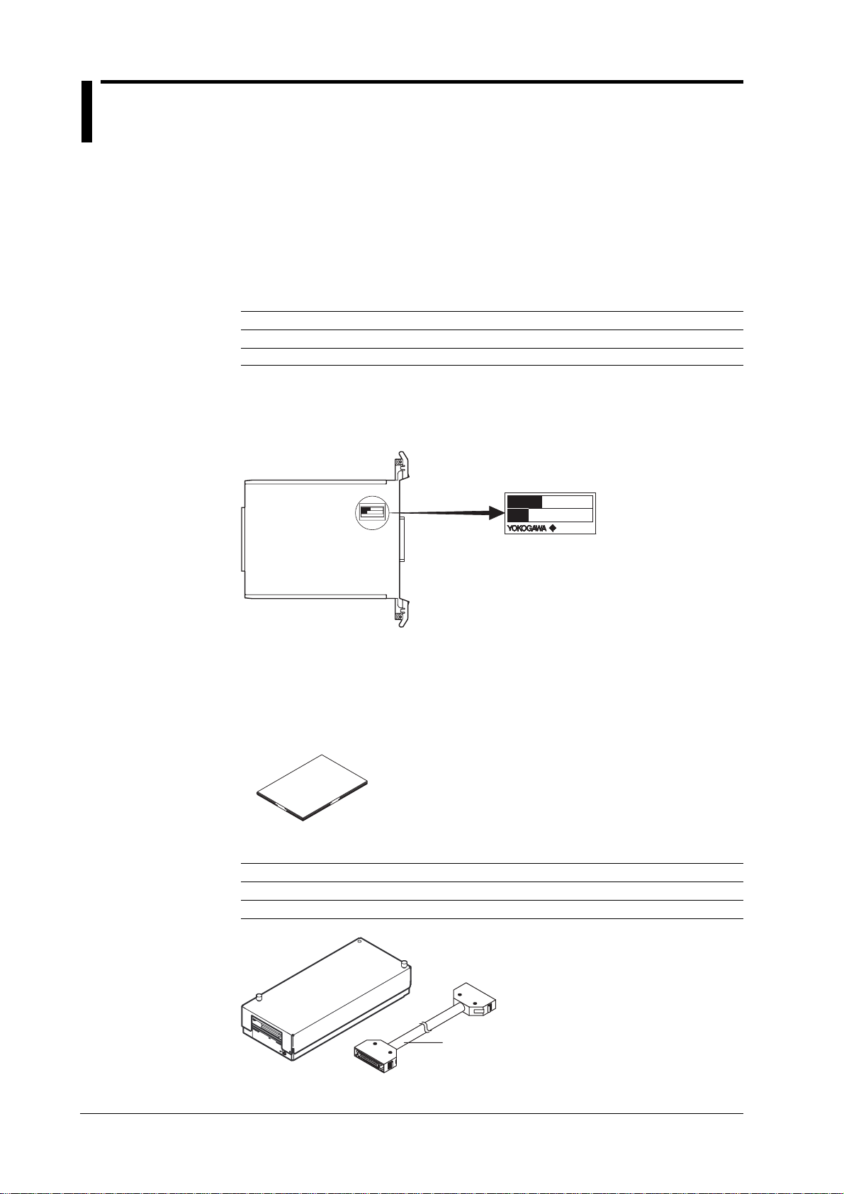
Checking the Contents of the Package
MODEL
NO.
Unpack the box and check the contents before operating the instrument. If some items
are missing or otherwise inconsistent with the contents description, please contact the
dealer from which you purchased them.
Measurement Module
Check that the model name given on the name plate matches the one on your order
form.
Model
Model Suffix Code Description
707231 WE7231 30-CH Fast Digital Thermometer Module
707231 /HE English help message
NO. (Instrument Number)
When contacting the dealer from which you purchased the instrument, please give them
the instrument number.
MODEL
NO.
Made in Japan
Accessories
The following standard accessories are supplied with the instrument. Make sure that all
items are present and undamaged.
One user’s manual (this document)
IM 707231-01E
Optional Accessories (Sold Separately)
Part Name Model Code Description
30-CH Scanner Box 707815 M4 screw terminal and 1 meter connecting cable
30-CH Scanner Box 707815/L3 M4 screw terminal and 3 meter connecting cable
Connecting cable
2
IM 707231-01E
Page 4

How to Use This Manual
Structure of the Manual
This manual consists of four chapters and an index as shown below.
Chapter Title Description
1 Functions Describes the system configuration and functions.
2 Hardware Preparation Explains how to install the module into the measuring
3Troubleshooting and Explains the procedures for troubleshooting and self-
Maintenance testing.
4 Specifications Outlines the specifications of the module.
Index An alphabetical index.
Conventions Used in This Manual
• Units
k Denotes 1000. (For example, 100 kHz)
K Denotes 1024. (For example, 720 KB)
• Boldface Characters
Characters set in boldface usually refer to items on-screen or on the instrument (such
as knobs, windows and buttons) with which the user interacts.
station, and how to connect the input.
• Symbols
The following symbols are used in this manual to alert you to important information.
This symbol is affixed to the instrument, and indicates that due to
possible danger to the user or instrument, the user’s manual should
be consulted. It is also printed on the corresponding reference
page in the user’s manual.
WARNING
CAUTION
Note
Describes precautions that should be observed to prevent injury or
death to the user.
Describes precautions that should be observed to prevent minor or
moderate injury to the user, or damage to the instrument.
Provides information that is important for proper operation of the
instrument.
IM 707231-01E
3
Page 5

4
IM 707231-01E
Page 6

Contents
Foreword .......................................................................................................................................... 1
Checking the Contents of the Package ............................................................................................. 2
How to Use This Manual...................................................................................................................... 3
Chapter 1 Functions
1.1 System Configuration and Block Diagram .............................................................................. 1-1
1.2 Operation Panel......................................................................................................................1-3
1.3 Setting Measurement Conditions............................................................................................ 1-5
1.4 Setting the Alarm ....................................................................................................................1-8
1.5 Waveform Display, Automatic Saving of Measured Data, File Conversion,
and Other Functions ............................................................................................................. 1-10
1.6 Name and Functions of Each Part........................................................................................ 1-11
Chapter 2 Hardware Preparation
2.1 Mounting Modules in the Measurement Station ..................................................................... 2-1
2.2 Connecting the 30-CH Scanner Box and the Input Signal Wire .............................................2-3
Chapter 3 Troubleshooting and Maintenance
3.1 Troubleshooting ......................................................................................................................3-1
3.2 Self Test ..................................................................................................................................3-2
3.3 Maintenance ...........................................................................................................................3-3
1
2
3
4
Index
Chapter 4 Specifications
4.1 Performance Specifications.................................................................................................... 4-1
4.2 Factory Default Settings ......................................................................................................... 4-4
4.3 General Specifications............................................................................................................4-5
4.4 Specifications for the 30-CH Scanner Box ............................................................................. 4-6
4.5 External Dimensions...............................................................................................................4-7
Index ................................................................................................................................ Index-1
IM 707231-01E
5
Page 7
Chapter 1 Functions
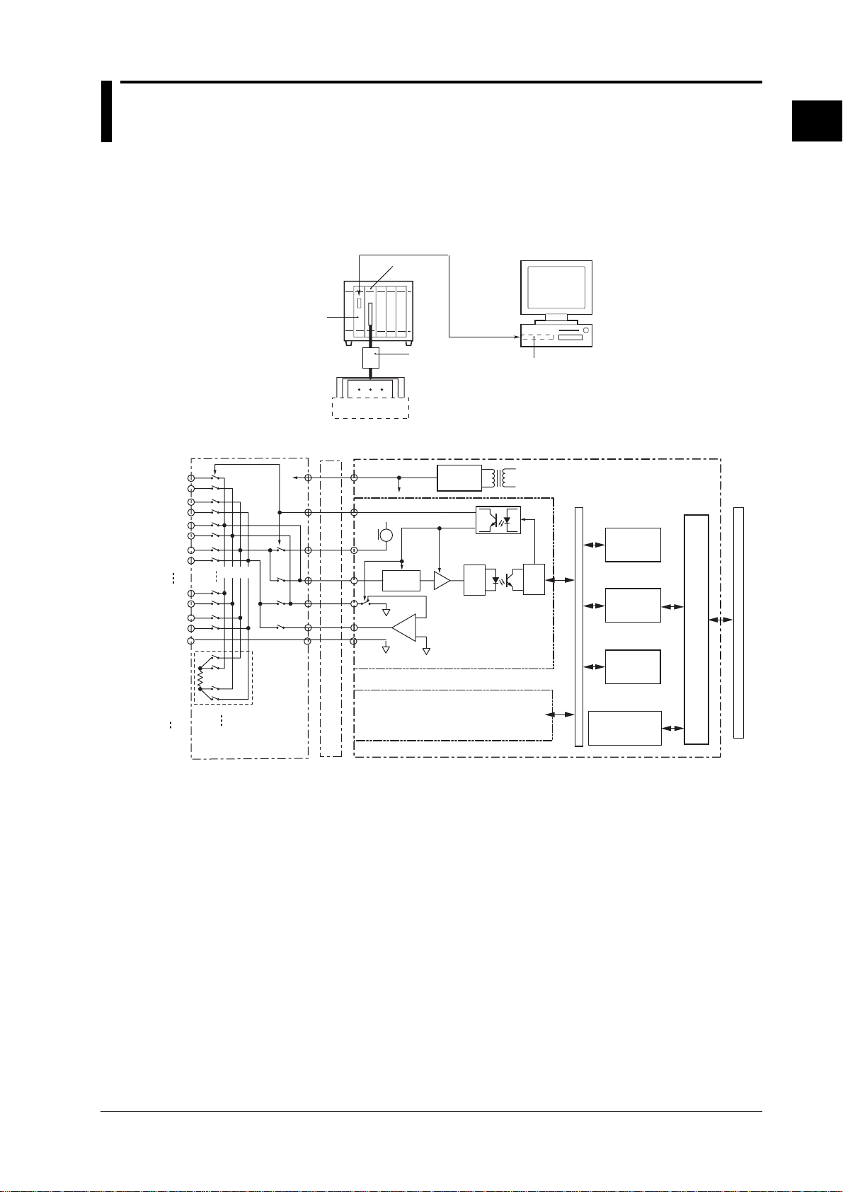
1.1 System Configuration and Block Diagram
System Configuration
The following is an example in which the 30-CH Fast Digital Thermometer WE7231 is
installed into the measuring station and the measuring station is connected to a PC with
the optical fiber cable.
1
Functions
Block Diagram
CH1
CH2
CH3
CH4
CH15
CH15c
G
Measuring station
Scan signal
RJC
Optical
interface
modules
Optical fiber cable
DUT
DC
Connecting cable
WE7231
30-CH Scanner
Box (sold separ
separately)
-
+
ATT
0/40dB
Amplifier
circuit
-
Voltage control circuit
+
Optical interface card
Power
supply
WE7231 30-CH Fast Digital
Thermometer Module
A/D
Acquisition
control circuit
Input signal processing
circuit for CH1-CH15
PC
Internal bus
CPU
32bits RISC
DPRAM
Memory
WE bus interface
CH16
CH30
CH30c
30-CH Scanner Box
Input signal processing
circuit for CH16-CH30
Module control
program
(flash memory)
WE bus
IM 707231-01E
1-1
Page 8

1.1 System Configuration and Block Diagram
Description of Operation
The 30-CH Scanner Box (sold separately) connects to the input connector of the 30-CH
Fast Digital Thermometer WE7231 using the connecting cable, and the devices under
measurement are connected to each terminal of the 30-CH Scanner Box. If the device
under measurement is a thermocouple or if you are measuring DC voltage, the input
terminals are connected using a 2-wire system. When measuring resistance or
resistance temperature detectors, a 4-wire system is used.
A scanning signal is sent through the connecting cable from the WE7231 to the 30-CH
Scanner Box, and the response from the device under measurement determines which
signals are selected for input to the WE7231.
With thermocouple or DC voltage input measurement, the input signal is modified in the
attenuator (A TT) and amplifier circuits then undergoes A/D conversion. When measuring
resistance such as in resistance temperature detectors, a constant current is given
through the connecting cable from the WE7231 to the device being measured, and in the
same manner as during thermocouple or DC voltage input measurement, the voltage
signal generated at both ends of the device being measured is input to the WE7231
where it undergoes A/D conversion. These converted digital signals are isolated in the
photocoupler and the digital data which represents the measured values is stored in
memory.
When measuring temperature, the reference junction temperature is measured using the
platinum resistance temperature detector inside the scanner box, and the CPU performs
reference junction compensation, or RJC, (this function can be turned ON/OFF) and
voltage-temperature conversion on the previously stored measurement data from the
thermocouple. These results are then re-stored. The data stored in memory can be
recalled from a PC through communications.
1-2
IM 707231-01E
Page 9
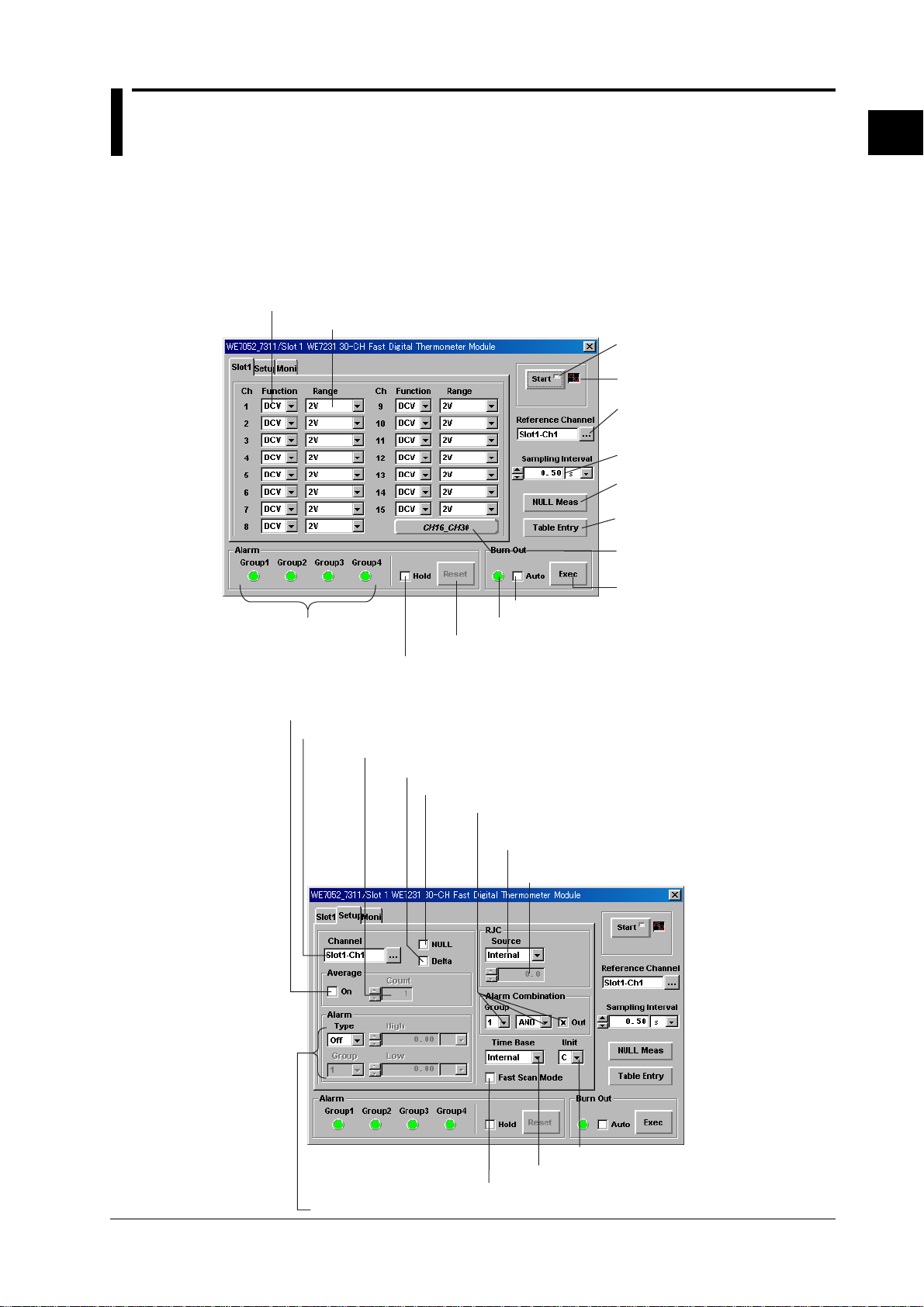
1.2 Operation Panel
The WE7000 Control Software installed in the PC is used to control the 30-CH Fast
Digital Thermometer WE7231. The WE7000 Control Software displays operation panels
similar to those shown in the figure below. This user’s manual does not explain the
operations of the operation panel or waveform monitor. For these operations, see the
WE7000 Control Software’s online help.
Basic Settings
Select the measurement function
Select the measuring range/type of thermocouple
Alarm occurrence
status indication
Select to put the alarm occurrence status indication on hold
1
Functions
Start/stop measurement
Turn the waveform monitor
ON and OFF
Select the reference channel
(for difference between channels
calculation)
Select the sampling interval
Execute NULL measurement
on channels set to use the null value
Display the Table Entry
window (see next page)
Display settings for
channels 16-30
Execute burn out detection
Select for automatic burn out detection
Burn out detection indicator
Click to release alarm occurrence status indication hold
Other Settings
Select to use the moving average as the measured values
Select the measurement channel
Set the number of samples for the moving average
Select to calculate the difference from the reference channel
Select to use the NULL value
Set alarm detection by group
Toggle the reference junction compensation (RJC)
between Internal and External
Input the reference junction temperature for
external reference junction compensation (RJC)
IM 707231-01E
Select the units of temperature
Select the time base
Select to enable fast scan mode
Set alarms for the measurement channels
1-3
Page 10
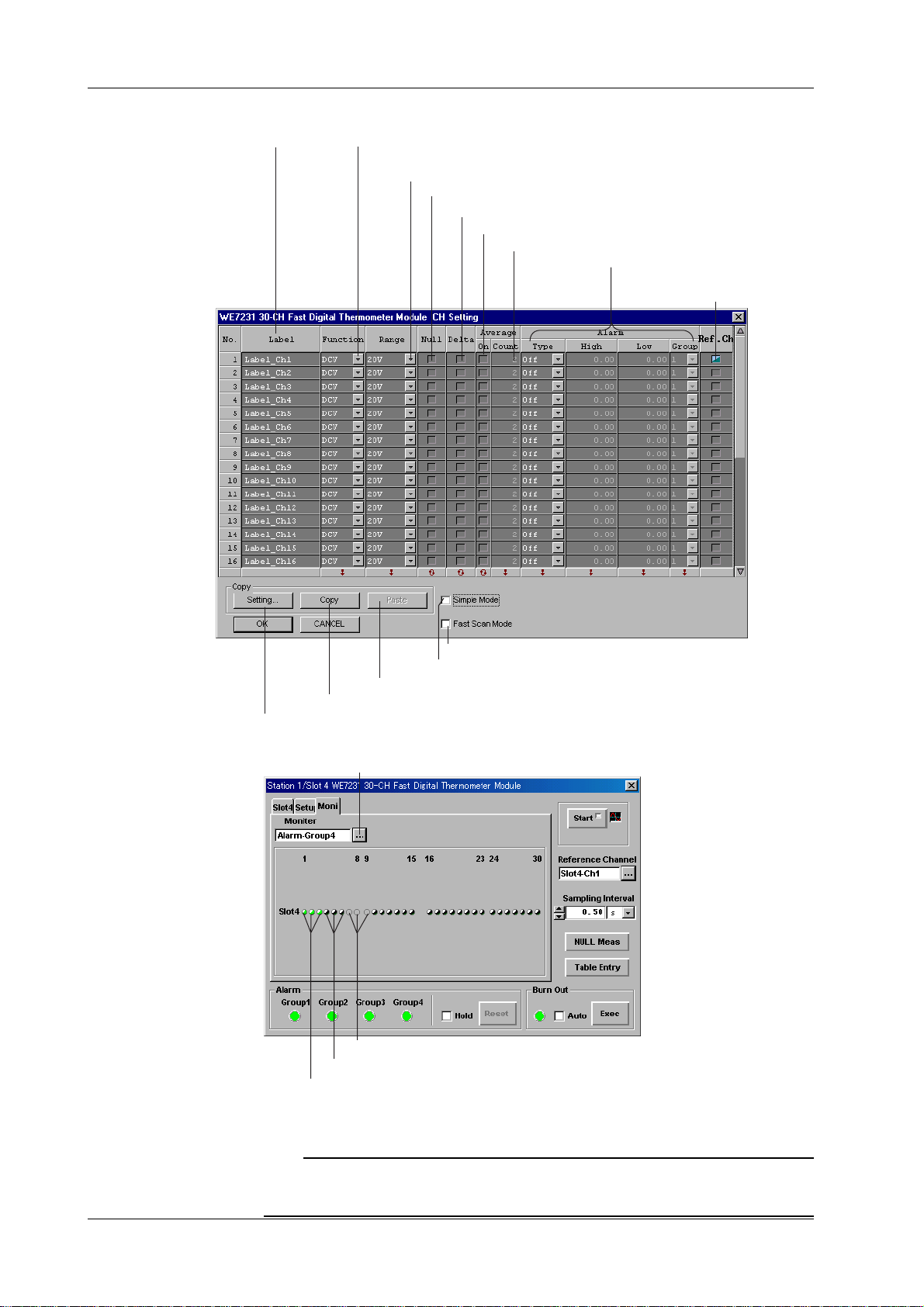
1.2 Operation Panel
Table Entry W indow
Select the Label
Select the measurement function
Select the type of thermocouple and resistance temperature
detector, and the measuring range
Select to use the NULL value
Select to calculate the difference from the reference channel
Select to average the measured values
Set the number of samples used for averaging
Enter the alarm output settings
Select the
reference channel
Select to enable fast scan mode
Select to hide alarm output and reference channel settings
Paste settings
Copy settings
Select items to be copied
Displaying Alarm Status and Burn out by Channel
Select groups for alarm status display or burn out
Grey indicator: channels in the measured group currently not being measured
Black indicator: channels not set to output alarms
Green indicator: channels from the measured group set to output alarms
(When alarm occurs, color changes from green to red)
When displaying the Burn Out status, the indicators of the burned
out channels change from green to red.
Note
When an alarm occurs frequently, the alarm status display overloads processing resources and
may make it impossible to perform panel operations such as setting changes. If this happens,
turn the Monitor setting OFF.
1-4
IM 707231-01E
Page 11

1.3 Setting Measurement Conditions
Selecting the Measurement Function
Choose from TC (thermocouple), DCV (DC voltage), RTD (resistance temperature
detector), and OHM (resistance). RTD (resistance temperature detector) and OHM
(resistance) can only be selected for the odd-numbered channels between CH1 and
CH15, or the even-numbered channels between CH16 and CH30. Also, if at least one
channel among CH1-CH15 or CH16-CH30 is set to RTD (resistance temperature
detector) or OHM (resistance), measurement on the even-numbered channels from CH1
to CH15 or the odd-numbered channels from CH16 to CH30 will no longer be possible.
Hence, you will not be able to enter measurement function settings on those channels.
Selecting the T ype of Thermocouple and Resistance Temperature Detector and the Range
The following is a breakdown by measurement function of the type, range, and
measurement range that can be selected.
Thermocouple (TC)
Type Measurement Range Resolution
K –200.0 to 1300.0°C 0.1°C
E –200.0 to 800.0°C 0.1°C
J –200.0 to 1100.0°C 0.1°C
T –200.0 to 400.0°C 0.1°C
1
Functions
NULL
IM 707231-01E
Resistance Temperature Detector (RTD)
Type Measurement Range Resolution*
Pt100 –200.0 to 650.0°C 0.01°C (0.1°C)
* The resolution in parentheses is for an integral time of 1 ms or 4 ms.
DC Voltage Input (DCV)
Range Measurement Range Resolution*
20 mV ±19.9999 mV 100 nV (1 µV)
200 mV ±199.999 mV 1 µV (10 µV)
2 V ±1.99999 V 10 µV (10 µV)
20 V ±19.9999 V 100 µV (1 mV)
*The resolution in parentheses is for an integral time of 1 ms or 4 ms.
Resistance (OHM)
Range Measurement Range Resolution*
20 OHM 0.0 to 19.9999 Ω 100 µΩ (1mΩ)
200 OHM 0.0 to 199.9999 Ω 1 µΩ (10 mΩ)
2 kOHM 0.0 to 1.99999 Ω 10 mΩ (100 mΩ)
20 kOHM 0.0 to 19.99999 kΩ 100 mΩ (1 Ω)
200 kOHM 0.0 to 199.99999 kΩ 1Ω (10 Ω)
2 MOHM 0.0 to 1.9999 MΩ 10 Ω (100Ω)
*The resolution in parentheses is for an integral time of 1 ms or 4 ms.
For each channel, you can set whether the null value is applied to measurement values.
When the NULL check box is selected, the measured value is equal to the actual value
minus the null value. Using the NULL value, the residual voltage can be cancelled, for
example when measuring in microvolts.
If the NULL check box is selected during measurement, the value measured immediately
thereafter is used as the null value. If the NULL check box is selected while
measurement is stopped, the value measured immediately after measurement starts is
used as the null value.
If you click the NULL Meas button, the null values of the channels whose NULL check
boxes are selected are measured again.
1-5
Page 12

1.3 Setting Measurement Conditions
Difference Computation of the Input Between Two Channels
You can assign a channel from other linked 30-CH Fast Digital Thermometer WE7231s
or equivalent modules as the reference channel, and calculate the difference against the
input of the reference channel, select the Delta check box of the channel on which to
calculate the difference.
The Moving Average of the Measured V alues
Select the On check box under Average to calculate the moving average of the
measured value. Select the average from 2 to 100.
Fast Scan Mode
If you select the Fast Scan Mode check box, only the odd-numbered channels from
groups 1 (CH1 to CH15) and 2 (CH16 to CH30) are available, thereby allowing a short
sampling interval.
When Fast Scan Mode is OFF (normal scan mode), all channels are enabled.
Sampling Interval
The sampling interval applies to all channels.
When using Internal Time Base
Normal Scan Fast Scan Integration time
0.10 to 0.19 s 0.06 to 0.11 s 1 ms
0.2 to 0.79 s 0.12 to 0.44 s 4 ms
0.8 to 3.49 s 0.45 to 1.99 s 16.7/20 ms*
3.50 s to 2.0 s to 100 ms
* The integration time is automatically switched depending on the frequency of the power supply.
When using External Time Base
Normal Scan Fast Scan Integration time
0.15 to 0.24 s 0.10 to 0.14 s 1 ms
0.25 to 1.09 s 0.15 to 0.59 s 4 ms
1.10 to 3.69 s 0.60 to 2.09 s 16.7/20 ms*
3.7 s to 2.1 s to 100 ms
* The integration time is automatically switched depending on the frequency of the power supply.
Note
• If any channel uses the 200 kΩ or 2 MΩ range, an additional 0.8 s for normal scan or 0.4 s for
fast scan are added.
• If you change the sampling interval after starting measurement, the Time Since the Start of
Measurement display will not be accurate.
Reference Junction Compensation
To carry out reference junction compensation using the internal circuitry, select Internal
from the RJC Source list box. Select External for external reference junction
compensation. Set the reference junction temperature when performing external
reference junction compensation. This setting applies to all channels.
1-6
IM 707231-01E
Page 13

Burn Out
Time Base
1.3 Setting Measurement Conditions
This function is available only when TC (thermocouple) is selected as the measurement
function. When the Auto check box is selected, burn out is automatically detected during
measurement. If you click the Exec button, burn out detection is executed. This setting
applies to all channels.
When a burn out is detected in the thermocouple, the indicators displayed on the Moni
tab of the operation panel turn red and Burn Out appears in the measured value display .
Also, current flows to connected thermocouples during burn out detection.
Note
• When the sampling interval is set to one of the following values, the indicators are displayed at
every other channel. 1-0.14 s, 0.2-0.24 s, 0.8-1.14 s, 3.5-3.84 s.
• When burn out is automatically detected, the load on the PC can be large so updating of the
displayed waveform may be temporarily disabled.
You can select whether to sample the input signal with the sampling interval based on
the module’s internal clock, or to sample to the time base signal (CMNCLK) of the
measuring station (the BUSCLK setting). If you select BUSCLK, time base signals with
an interval shorter than the specified interval are ignored.
1
Functions
Units for T emperature Measurement
In the Unit box, select the units of temperature (C, K, or F) to be used by the module (or
all modules if more than one are linked) during temperature measurement.
IM 707231-01E
1-7
Page 14

1.4 Setting the Alarm
Alarm Type
Select the alarm type from the following choices.
Off: Do not detect alarms
Rise: Output when measured value changes from a value less than the specified upper
limit to a value greater than the specified upper limit.
Input signal
Alarm
High level
Fall: Output when a measured value changes from a value exceeding the specified
lower limit to a value less than the lower limit.
High: Output when a measured value is greater than or equal the specified upper limit.
Low: Output when a measured value is less than or equal the specified lower limit.
Input Signal
Alarm
Low level
In: Output when a measured value is between the specified upper and lower limits
(inclusive).
Out: Output when a measured value is less than the specified lower limit or greater
than the specified upper limit.
Input Signal
High level
Low level
1-8
Alarm
Group
You can divide the channels for which alarms were set into four groups. The alarm
occurrence status for each group is displayed in the operation panel, and can be output
to external devices by selecting the Out check box. You can assign any channel to any
group.
Combination
Select the condition under which alarms are output for each group.
OR: output alarm if any one channel in the group generates an alarm
AND: output alarm when all channels in the group generate an alarm
IM 707231-01E
Page 15

1.4 Setting the Alarm
Alarm Output
When the Out check box is selected, you can output the alarm occurrence status as a
bus trigger to the measuring station’s BUSTRG1 or BUSTRG2.
An alarm is output if any of the groups for which alarm output was specified generate an
alarm.
When an alarm occurs and the bus trigger signals are set to output from the WE7231 in
the Trigger Source/Time Base Source/Arming settings dialog box, if the alarm output
conditions are Rise/Fall when the conditions are met, the bus trigger signal is set to True
for approximately 1 µs. When the alarm output conditions are High, Low, In, or Out, the
bus trigger signal is True for as long as the conditions are met. For information about the
settings in the Trigger Source/Time Base Source Setting dialog box, see section 4.6,
“Setting the Trigger Source/Time Base Source/Arming” in the WE7000 User’s Manual (IM
707001-01E).
Example of Alarm Output
1
Functions
CH1 input
signal
Alarm
(type: High)
CH2 input
signal
Alarm
(type: Rise)
(When the combination is OR)
Event output
BUSTRG output
(When the combination is AND)
Event output
BUSTRG output
TRIG_HIGH
TRIG_LOW
TRIG_PULSE
TRIG_HIGH
TRIG_LOW
TRIG_PULSE
High level
High level
Alarm Status Indicator
The alarm occurrence status for each group is displayed according to the combination
setting. Also, when you select the group you wish to display under the Moni tab, the
button displaying the alarm status appears. You can confirm the alarm status of each
channel, and when an alarm occurs, the button color turns from green to red.
IM 707231-01E
Alarm Status Indicator Hold
When the Hold check box is selected, the alarm occurrence status indicator is held from
the point when an alarm occurs. If you click Reset, the hold is released.
1-9
Page 16

1.5 Waveform Display, Automatic Saving of
Measured Data, File Conversion, and Other
Functions
The following functions are common to all measurement modules controlled by the
WE7000 Control Software. For details, see the WE7000 User’s Manual (IM 70700101E).
Controlling the Timing of Measurement Start (Arming)
You can control the measurement start timing using the arming signal which is set in the
Trigger Source/T ime Base Source/Arming Setting dialog box. When the measurement
module is connected to the arming signal (ARM) bus in the Trigger Source/Time Base
Source/Arming Settings dialog box, the arming signal enters a wait state when the user
clicks the Start button in the operation panel, and measurement starts when the arming
signal becomes True. For information about the settings in the T rigger Source/Time Base
Source/Arming Setting dialog box, see section 4.6, “Setting the Trigger Source/Time
Base Source/Arming” in the WE7000 User’s Manual (IM 707001-01E).
Waveform Display
You can display measured data as a waveform on the WE7231. When measurement is
started on WE7231’s operation panel, waveforms are automatically displayed by default
in the WE7000 Control Software’s waveform monitor .
Automatic Saving
Besides saving the waveform data from those displayed in the waveform monitor,
measured data can also be automatically saved. You can select to save the data to one
file or by specifying the number of data points you may save to multiple files.
File Conversion
Saved measurement data can be converted from ASCII data in CSV format (*.csv) or
physical values in 32-bit floating point format (*.wvf, conforming the IEEE754-1985
standard).
Measured Data Scaling
Set two arbitrary points from the measured values (VP1, VP2) and the physical value
corresponding to those measured values (SP1, SP2). The scale conversion equation
(y=mx+b) is determined based on these four values. The measured values are
converted to physical values according to this equation, and can be displayed in a
waveform or saved as measurement data.
Physical
values
SP2
SP1
Y=ax + b
VP1
Measured values
VP2
1-10
IM 707231-01E
Page 17

1.6 Name and Functions of Each Part
Front Panel
Start indicator
Lights when
measurement starts
Input connector
Connector for the
scanner box
1
Functions
* See page 2-5 for the names and functions of each part of the 30-CH Scanner Box
(sold separately).
IM 707231-01E
1-11
Page 18

Chapter 2 Hardware Preparation
2.1 Mounting Modules in the Measurement Station
Preparation
Before shipping, a cover plate is affixed to each slot on the measuring station as shown
below. Confirm that there is no power being supplied to the measuring station, then
loosen the two attachment screws and remove the cover plate of the slot into which a
module will be installed. Please note that the left-most slot is reserved for
communications modules, and cannot be used for the WE7231.
* The example below shows the WE400 Measuring Station.
Dedicated slot for optical interface module
Available slot
Attachment screw
Cover plate
Attachment screw
2
Hardware Preparation
Installing the 30-CH Fast Digital Thermometer Module
WARNING
• Be sure to tightly fasten the upper and lower attachment screws. Connecting an
input cable without first tightening the screws may result in electric shock
because the protective grounding of the measuring station may be rendered
ineffective (depending on the power supply cord).
CAUTION
•To avoid damage to the instrument, turn OFF the standby power switch on the
measuring station when installing a measurement module.
• When inserting the module into the slot, be careful not to pinch your finger in the
release lever. Also, the module guide protrudes from inside the slot, so do not
insert your hand into the slot.
• Do not remove the cover plate from any slot unless a module will be mounted
into it. Doing so could cause problems, for example if the temperature rises. The
cover plate also suppresses the potentially damaging effects of magnetic waves.
IM 707231-01E
Insert the module along the guide rail of the slot from which you removed the cover plate.
Push the module until it clicks into the connector. Be careful not to get your fingers
caught in the ejection lever while inserting the module. When the module is securely
inserted, fasten the module attachment screws (tightening torque: 0.6 to 0.7 N-m).
To remove the module, loosen the module attachment screws and pull the ejection lever
from the inside to the outside. This will force the module out of the slot.
See illustration on the next page.
2-1
Page 19

2.1 Mounting Modules in the Measurement Station
Module attachment
screw
Module attachment screw
Note
When synchronization of the measurements of multiple input signals is desired (linking the
modules), install the multiple digital thermometer modules in adjacent slots.
• When removing the module
Ejection lever
2-2
IM 707231-01E
Page 20

2.2 Connecting the 30-CH Scanner Box and the Input Signal Wire
You cannot connect the input signal wires directly to the 30-CH Fast Digital Thermometer
Module WE7231. To connect the input signal wires, you need the 30-CH Scanner Box
(model 707815, sold separately).
Connecting the 30-CH Scanner Box to the Input Signal Wire
WARNING
• There is a danger of electric shock between the input terminals since they only
have functional isolation. Functional isolation means isolation that removes the
effect of noise from the electric potential difference occurring between 2 points,
and is intended to satisfy measurement specifications rather than to provide
protection from electric shock.
• The guard terminal is common within groups (CH1-CH15 and CH16-CH30).
Also the guard terminal is connected to the L terminal of the measurement
channel inside the module. If the potential of the L terminal at each channel
differs, the module or connected device may be damaged so don’t use the guard
terminal.
2
Hardware Preparation
CAUTION
• Do not apply a voltage exceeding the following levels, as it may damage the
module.
Maximum allowable input range: 30 VACrms, 42.4 Vpeak or ±60 VDC between
H and L.
(Overvoltage category: CA T I and II)
Maximum noise across channels: 60 VACrms or ±100 VDC
• Do not apply the voltage exceeding 60 V ACrms or ±100 VDC between input
channels, as it may damage the module and 30-CH Scanner Box.
• Remove the 30-CH Scanner Box from the module when connecting the signal
wires to avoid damaging the module.
• Do not apply voltage between the L terminal and guard terminal (terminal with
the G signal) as this may result in damage to the module and any connected
devices. The guard terminal is connected to the circuit common inside the
module. When measuring voltage, the guard terminal and L terminal form a
direct connection since the L terminal is connected to the circuit common. Also,
when measuring resistance, L terminal is the standard for the circuit common.
Note
• When performing internal reference junction compensation on the thermocouple input, consider
the following suggestions for stabilizing the temperature at the terminal section.
• Make sure the terminal cover is in place.
• Keep the temperature constant in the area where the instrument is operating.
• Do not use thick wires (a cross sectional area of 0.5 mm2 or more) that have large radiation
effects.
• Place the 30-CH Scanner Box at a sufficient distance from the point of measurement so that
the heat from the point of measurement will be conducted through the wiring rather than to
the 30-CH Scanner Box.
•To prevent noise, you can use the functional grounding terminal on the side of the 30-CH
Scanner Box to ground the guard terminal or L terminal (see next page).
IM 707231-01E
2-3
Page 21

2.2 Connecting the 30-CH Scanner Box and the Input Signal Wire
• Thermocouple/V oltage Measurement
Connects to the H and L terminals of channels 1-30 using a 2 wire system. Each H
and L terminal of channel 15C and 30C is a dedicated input terminal for resistance
temperature detector/resistance measurement. Don’t connect these when measuring
thermocouple/voltage.
• Resistance T emperature Detector/Resistance Measurement
Connect using a 4 wire system. When the measurement function is set to RTD
(resistance temperature detector) or OHM (resistance), measurement is performed on
the input signal voltages from the odd-numbered channels between CH1 and CH15, or
the even-numbered channels between CH16 and CH30. The next-numbered channel
becomes the current output terminal of the voltage measurement channel. For
example, if channel 1’s H and L terminals are the voltage input terminals, then channel
2’s H and L terminals are the current output terminals. The each H and L terminal of
channel 15 or 30 become current output terminals.
i
CH2’s H terminal
CH1’s H terminal
V
CH1’s L terminal
CH2’s L terminal
Mixing 2 and 4 Wire Systems
The terminals on the scanner box are divided into groups 1 and 2, and you can specify a
2 or 4 wire system for each group. Even for one channel, when you select measurement
with a 4 wire system (resistance temperature detector/resistance measurement), you can
only measure the odd-numbered channels from group 1 or even-numbered channels
from group 2. However you can mix 2 and 4 wire systems; for example if you measure a
resistance temperature detector or resistance with a 2 wire system on CH1, you can
have a 4 wire system such as the thermocouple or voltage on CH3.
Group 1: CH1-CH15, Group 2: CH16-CH30
2-4
IM 707231-01E
Page 22

2.2 Connecting the 30-CH Scanner Box and the Input Signal Wire
Attaching and Removing the Terminal Cover
Unscrew the two attachment screws in the upper part of the 30-CH Scanner Box and
remove the cover as shown in the diagram below. After connecting all of the input signal
wires to the input terminals, fasten the input signal wire with the cable clamp, re-attach
the terminal cover, and tighten the terminal cover attachment screws. Use crimp-on lugs
to ensure the connection to the input terminal is secure, and if it’s not necessary to use
the cable clamp, you can remove the clamp to widen the opening, and allow thicker
wiring. When connecting to all input terminals, the maximum allowable cross-sectional
area per cable (due to the restriction on the area of the cover opening) is the following.
With a cable clamp: 2 mm
Terminal cover attachment screws (2)
2
, without a cable clamp: 19 mm
2
Terminal
cover
2
Hardware Preparation
Cable attachment
screw
Cable clamp
Cable clamp
attachment screw
Functional ground terminal
Example of terminal arrangement
M4 screw for each terminal
Connector
BETWEEN H AND L
TERMINAL 30VACrms,
42.4Vpeek OR 60VAC
BETWEEN L TERMINALS
Guard terminal
L terminal (1)
H terminal (1)
L terminal (15)
H terminal (15)
L terminal (15C)
H terminal (15C)
Guard terminal
AND CASE 150V MAX
CAT
G
L
116
H
L
217
H
(1C) (16C)
L
318
H
L
419
H
(3C) (18C)
L
520
H
L
621
H
(5C) (20C)
L
722
H
L
823
H
(7C) (22C)
L
924
H
L
10 25
H
(9C) (24C)
L
11 26
H
L
12 27
H
(11C) (26C)
L
13 28
H
L
14 29
H
(13C) (28C)
L
15 30
H
L
(15C)
G
G
L
L
L
L
L
L
L
L
L
L
L
L
L
L
L
(30C)
LH
G
Guard terminal
H
H
H
H
H
H
H
H
H
H
H
H
H
H
H
H
H terminal (16)
L terminal (16)
H terminal (30)
L terminal (30)
H terminal (30C)
L terminal (30C)
Guard terminal
IM 707231-01E
Functional ground terminal
Cable clamp
2-5
Page 23

2.2 Connecting the 30-CH Scanner Box and the Input Signal Wire
Connecting to a Module
CAUTION
•Turn OFF the standby power switch on the measuring station when connecting a
module to the 30-CH Scanner Box.
As in the diagram below, use the cable that came with the 30-CH Scanner Box between
the scanner box and the module input connector.
Connection Cable
(Accessory for the 30-CH Scanner Box)
30-CH Scanner Box
2-6
IM 707231-01E
Page 24

Chapter 3 Troubleshooting and Maintenance
3.1 Troubleshooting
• If servicing is required, or if the instrument is not operating correctly after performing
the corrective actions listed below, contact your nearest YOKOGAWA dealer as listed
on the back cover of this manual.
•To verify that the module is operating correctly , perform the self test described on the
next page.
Problem Possible Causes/Corrective Actions Reference Page
Module does not operate. Check that the module is installed correctly into the station. 2-1, *
Also, install the module into another slot, and check whether it will
operate there. If it operates in the other slot, the measuring station is
likely to have malfunctioned.
If the module is installed correctly and does not operate, the fuse might
have melted, the connector might be bad, or the IC may have
malfunctioned.
In any case, contact your nearest YOKOGAW A dealer to have it repaired.
Waveform data cannot be Check that the input signal wires are connected properly. 2-3 to 2-6
acquired. Also check the connection between the 30-CH Scanner Box and
the module.
Noise enters the input signal If the signal line and the AC power supply line are close to each other, 2-3
move them apart. Also make sure that the signal line is away from the
noise source.
Change to a shielded signal wire if you are not already using one. 2-3
Measured values are not correct. Check that the ambient temperature and humidity are within the 4-5
allowed ranges. If you did not allow a warm-up time of 30 minutes,
try measuring again after the warm-up time has passed.
Check to see that the input signal level is not exceeding the 4-1, 4-2
measurement range.
Temperature measurement is not Check that the RJC setting is correct. 1-3, 1-5
correct. Check whether the thermocouple type and polarity are set properly.
Check to see that the thermocouple is not burnt out after clicking the
Exec button under Burn Out.
Check whether the terminal cover for the 30-CH Scanner Box is 2-5
attached.
Check to see that there is no draft in the area where the instrument is
located that might cause significant changes in temperature.
Check to see that the two types of thermocouple wires are not too far
apart, the tip is not touching a metal object, and that the thermocouple
is being handled properly .
Check to see that the input signal level from the object being measured
is within the measurement range.
The displayed waveform does not Check whether the measurement has been started on the operation 1-3
get updated. panel.
Check whether the sampling interval is set properly on the operation 1-6
panel.
The waveform is not displayed. Check whether measurement has been started on the operation panel. 1-3
If the time base setting is BUSCLK, check to see that the time base 1-6, *
source is set properly in the Trigger Source/Time Base Source/Arming
Setting dialog box of the WE7000 Control Software.
Check to see that the input signal level from the object being measured
is within the measurement range.
The waveform monitor is not Check that the waveform monitor ON/OFF button located to the right of 1-3
displayed. the Start button on the operation panel is turned ON.
* See the WE7000 User’s Manual (IM707001-01E).
3
Troubleshooting and Maintenance
IM 707231-01E
3-1
Page 25

3.2 Self Test
If you believe that the module is not operating correctly, perform the self test according to
the following steps.
Executing the Self T est
1. In the WE7000 Control Software, select System > Self T est .
2. In the Self Test dialog box, select the station name and slot number of the module to
be tested, and click the Execute button.
“Executing” is displayed in the Result box.
→
Verifying Test Results
If a value other than 0 is displayed in the Result box of the Self Test dialog box, the
module is probably malfunctioning. Contact your nearest YOKOGAW A representative as
listed on the back cover of this manual.
3-2
IM 707231-01E
Page 26

3.3 Maintenance
Maintenance of Parts
There are no parts in this module that require periodic replacement.
Calibration
We recommend that you calibrate the measurement module once a year to assure its
measurement accuracy.
Contact your nearest YOKOGAW A representative as listed on the back cover of this
manual for calibration.
3
Troubleshooting and Maintenance
IM 707231-01E
3-3
Page 27

Chapter 4 Specifications
4.1 Performance Specifications
Input Signal
Thermocouple: K, E, J, T (2 wire system)
DC voltage: 20 mV, 200 mV, 2 V , 20 V (2 wire system)
Resistance temperature detector: Pt100 (4 wire system)
Resistance: 20 Ω, 200 Ω, 2 kΩ, 20 kΩ, 200 kΩ, 2 MΩ (4 wire
system)
Number of input channels
With only 2 wire systems connected: 30, with only 4 wire systems connected: 16
Groups: Group 1 (CH1-CH15), Group 2 (CH16-CH30)
Possible to specify wiring (2 wire system/4 wire system) for each group.
Input format
Floating unbalance input, isolated between input and ground
Input terminal type
Multi-pole square connector (to connect the 30-CH Scanner Box, sold separately)
4
Specifications
Measurement Mode
Sampling interval
Normal Scan: all channels (30 channels total)
Fast Scan: odd channels from group 1, and even channels from group 2 (16
channels total)
Internal time base
Normal scan: 0.10 s to 60 min (0.9 s or more if any channel uses the 200 kΩ/2 MΩ
range)
Fast Scan: 0.06 s to 60 min (0.46 s or more if any channel uses the 200 kΩ/2 MΩ
range)
Normal Scan Fast Scan Integration time
0.10 to 0.19 s 0.06 to 0.11 s 1 ms
0.2 to 0.79 s 0.12 to 0.44 s 4 ms
0.8 to 3.49 s 0.45 to 1.99 s 16.7/20 ms
3.5 s to 2.0 s to 100 ms
If any channel uses the 200 kΩ or 2 MΩ range, an additional 0.8 s and 0.4 s are added during
normal scan and fast scan. Can be specified in units of 0.01 s for the 0.06 s to 60.0 s range and
60.0 s to 60.0 min range.
External Time Base
Normal Scan: 0.15 s to 60 min (0.95 s or more if any channel uses the 200 kΩ/2 MΩ
range)
Fast Scan: 0.1 s to 60 min (0.5 s or more if any channel uses the 200 kΩ/2 MΩ
range)
IM 707231-01E
Normal Scan Fast Scan Integration time
0.15 to 0.24 s 0.10 to 0.14 s 1 ms
0.25 to 1.09 s 0.15 to 0.59 s 4 ms
1.10 to 3.69 s 0.60 to 2.09 s 16.7/20 ms
3.7 s to 2.1 s to 100 ms
If any channel uses the 200 kΩ or 2 MΩ range, an additional 0.8 s and 0.4 s are added during
normal scan and fast scan. Can be specified in units of 0.01 s for the 0.06 s to 60.0 s range and
60.0 s to 60.0 min range.
4-1
Page 28

4.1 Performance Specifications
Measurement Range and Resolution
TC Input
Type Measurement Range Resolution
K –200.0 to 1300.0°C 0.1°C
E –200.0 to 800.0°C 0.1°C
J –200.0 to 1100.0°C 0.1°C
T –200.0 to 400.0°C 0.1°C
Units: °C, K or °F can be selected.
Reference junction compensation: internal or external can be selected.
Burn out: auto or manual detect can be selected.
Resistance temperature detector (4 wire system)
Range Measurement Range Resolution Measured Current
Pt100 –200 to 650°C 0.01 (0.1)°C1 mA
The resolution in the parentheses is for an integration time of 1 ms or 4 ms.
DC voltage
Range Maximum display Resolution
20 mV 19.9999(19.999) 100 nV (1 µV)
200 mV 199.999(199.99) 1 µV (10 µV)
2 V 1.99999(1.9999) 10 µV (10 µV)
20V 19.9999(19.999) 100 µV (1 mV)
The resolution in the parentheses is for an integration time of 1 ms or 4 ms.
Accuracy
Resistance (4 wire system)
Range Maximum display Resolution Measured Current
20 Ω 19.9999(19.999) 100 µΩ (1 mΩ)1 mA
200 Ω 199.999(199.99) 1 mΩ (10 mΩ)1 mA
2 kΩ 1.99999(1.9999) 10 mΩ (100 mΩ)1 mA
20 kΩ 19.9999(19.999) 100 mΩ (1 Ω) 100 µA
200 kΩ 199.999(199.99) 1 Ω (10 Ω) 10 µA
2 MΩ 1.99999(1.9999) 10 Ω (100Ω)1 µA
Open terminal voltage: 10 V max.
The resolution in the parentheses is for an integration time of 1 or 4 ms.
Thermocouple ±(% of reading +°C)
Gain error (%) Offset error °C (for every integration time)
Range Measurement Range 100 ms 16.7/20 ms 4 ms 1 ms
K –200≤t<–100°C 0.035 0.5 0.6 2 3.0
–100≤t<1300°C 0.035 0.3 0.4 1 1.5
E –200≤t<–100°C 0.035 0.3 0.4 1.5 2.0
–100≤t<800°C 0.035 0.2 0.3 1.0 1.5
J –200≤t<–100°C 0.035 0.4 0.5 2.0 2.5
–100≤t<1100°C 0.035 0.2 0.3 2.0 1.5
T –200≤t<–100°C 0.035 0.5 0.6 2.5 3.5
–100≤t<400°C 0.035 0.3 0.4 1.5 2.0
Resistance temperature detector ±(% of reading +°C)
Gain error (%) Offset error °C (for every integration time)
Range Measurement Range 100 ms 16.7/20 ms 4 ms 1 ms
Pt100 –200≤t<200°C0 0.3 0.3 0.4 0.5
200≤t<650°C 0.1 0.1 0.1 0.2 0.3
4-2
IM 707231-01E
Page 29

4.1 Performance Specifications
DC voltage ±(% of reading + digit)
Range Gain error (%) 100 ms 16.7/20 ms 4 ms 1 ms
20 mV 0.03 60 80 30 50
200 mV 0.025 8 10 4 8
2 V 0.02 5 7 3 6
20 V 0.035 5 7 3 6
Offset error (digit) (for every integration time)
Resistance ±(% of reading + digit)
Range Gain error (%) 100 ms 16.7/20 ms 4 ms 1 ms
20 Ω 0.04 60 80 30 50
200 Ω 0.04 8 10 4 8
2 kΩ 0.035 6 8 3 6
20 kΩ 0.035 6 8 3 6
200 kΩ 0.035 6 8 3 6
2 MΩ 0.3 20 25 40 60
Reference Junction Compensation Accuracy
1°C (the value not including the noise component when the temperature of the 30-CH
Scanner Box is balanced).
Temperature coefficient
• In the 20 V range: ±(accuracy/5)/°C
• Other ranges: ±(accuracy/10)/°C
However, at 5 to 18°C or 20 to 40°C
Computaion
The calculations below can be turned ON/OFF for each channel.
• Difference
Difference from the reference channel. When modules are linked, the difference can
be computed across modules. However, difference cannot be computed between two
different measurement functions.
•NULL
Sets the NULL value for each channel.
• Moving Average
100 samples maximum. Can be specified for each channel.
Offset error (digit) (for every integration time)
4
Specifications
Alarm Output
IM 707231-01E
Can output trigger signals to the internal bus (BUSTRG1/BUSTRG2) of the measuring
station on the AND/OR condition of the alarm detection result specified by high, low, in,
out, rising, or falling of each channel.
4-3
Page 30

4.2 Factory Default Settings
Function (measurement function): TC
Range (measurement range): T ype T
Reference Channel: CH 1 on the module
Sampling Interval: 0.80 s
Burn Out (Auto Detect): Off
Alarm Hold: Off
Channel: CH 1 on the module
NULL (use NULL value): Off
Delta (difference measurement): Off
Averaging: Off
Type (alarm type): Off
RJC Source (internal/external switch for the reference junction compensation): Internal
Alarm Combination: AND
Out (alarm output): On
Time Base: Internal
Unit (units of temperature measurement): °C
Fast Scan Mode: Off
Monitor (group selection of alarm status for each channel/burn out status display): Off
4-4
IM 707231-01E
Page 31

4.3 General Specifications
Safety Standards
Complies with CSA C222 No. 1010.1 and EN61010-1, conforms to JIS C1010-1
Standard Operating Conditions
Ambient T emperature: 23±5°C
Ambient Humidity: 50±10% RH
After the warm-up time has passed.
Warm-up Time
At least 1 hour
Operating Condition
Same as those of the measuring station
Storage Condition
Temperature: –20 to 60°C
Humidity: 20 to 80% RH (no condensation)
Maximum Allowable Input Range
30 VACrms, 42.4 Vpeak or ±60 VDC
(Overvoltage category: CA T I and II)
Maximum Common Mode V oltage
150 V rms or ±150 VDC between ground and L terminal
Maximum Noise between Channels
60 VACrms, 84.8 Vpeak or ±100 VDC
Input Resistance
1 GΩ or more (except, 10 MΩ ±1% for the 20 V range)
Allowable Signal Resistance
1 kΩ or lower (when using thermocouple or resistance temperature detector)
Normal Mode Rejection Ratio
Approximately 60 dB
(at an integration time of 16.7 ms or longer, 50/60 Hz ±0.1%)
Common Mode Rejection Ratio
Approx. 120 dB or more.
(at an integration time of 16.7 ms or longer, 50/60 Hz ±0.1%, and unbalanced input Rs=1
kΩ)
Withstand V oltage
1500 VAC at 60 Hz between ground and L terminal for one minute
Power Consumption
7.0 VA (typical value* at 100 V/50 Hz when connected to the 30-CH Scanner Box (model:
707815))
External Dimensions
Approx. 33(W) × 243(H) × 232(D) mm (projections excluded)
Weight
Approx. 0.8 kg
Number of Used Slots
1
Standard Accessories
User’s manual (1)
Optional Accessories
707815 30-CH Scanner Box (cable length: 1 m)
707815/L3 30-CH Scanner Box (cable length: 3 m)
4
Specifications
* The typical value is a typical or average value. It is not strictly guaranteed.
IM 707231-01E
4-5
Page 32

4.4 Specifications for the 30-CH Scanner Box
Number of Input Channels
30
Input Format
Isolation between input and ground
Functional isolation between the Input channels*.
* Functional isolation means insulation that removes the effect of noise from the electric potential
difference occurring between 2 points, and is intended to satisfy measurement specifications
rather than to provide protection from electric shock.
Input T erminal type
M4 Screw
The maximum allowable cross-sectional area per one cable (due to the restriction on
the area of the cover opening) when connecting to all input terminals.
When using the cable clamp: 2 mm
Without the cable clamp: 19 mm
Operating Conditions
Temperature: 5 to 40°C
Humidity: 20-80% RH (except maximum wet-bulb temperature of 29°C, no
condensation)
Maximum Allowable Input Voltage
30 VACrms, 42.4 Vpeak or ±60 VDC between H and L terminals (overvoltage category:
CAT I and II).
Maximum Noise between Channels
60 VACrms, ±100 VDC.
Insulation Withstand Voltage
Between voltage input terminals and case: 60 Hz 1500 V ACrms for one minute
Insulation Resistance
Between input terminal and ground: 10 MΩ (500 VDC) or more
Modules that can be Connected
707231 (WE7231 30-CH Fast Digital Thermometer Module)
Weight
Approx. 1.3 kg
External Dimensions
Approx. 123(W) × 76(H) × 305(D) mm (projections excluded)
2
2
4-6
IM 707231-01E
Page 33

4.5 External Dimensions
WE7231 30-CH Fast Digital Thermometer Module
33
START
242.4
30-CH,FAST
30-CH Scanner Box (Model 707815)
Main Unit
Units: mm
227 4.5
4
Specifications
132 305
Connecting cable
707815: 1 m
707815/L3: 3 m
106.5 59.5
If not specified, the tolerance is ±3%. However, if less than 10 mm, the tolerance is ±0.3
mm.
IM 707231-01E
4-7
Page 34

Index
Index
Symbols
*.csv ................................................................................. 1-10
*.wvf ................................................................................. 1-10
2 wire system ..................................................................... 2-4
30-CH Scanner Box ...........................................................2-3
4 wire system ............................................................. 2-4, 2-4
A
AND ................................................................................... 1-8
Alarm.................................................................................. 1-8
Alarm Type......................................................................... 1-8
Arming.............................................................................. 1-10
Automatic Saving ............................................................. 1-10
Average.............................................................................. 1-6
B
Burn Out............................................................................. 1-7
C
Combination ....................................................................... 1-8
Contents of the Package....................................................... 2
Controlling the Timing of Measurement Start................... 1-10
D
DC Voltage Input................................................................ 1-5
DCV ................................................................................... 1-5
Delta................................................................................... 1-6
Difference Computation ..................................................... 1-6
E
External .............................................................................. 1-6
F
Fall ..................................................................................... 1-8
Fast Scan Mode ................................................................. 1-6
File Conversion ................................................................ 1-10
Front Panel ...................................................................... 1-11
Function ............................................................................. 1-5
M
Measurement Function ...................................................... 1-5
Model .................................................................................... 2
Moving Average ................................................................. 1-6
N
NO......................................................................................... 2
NULL .................................................................................. 1-5
O
OHM................................................................................... 1-5
OR...................................................................................... 1-8
On ...................................................................................... 1-6
Out ..................................................................................... 1-8
R
RTD .................................................................................... 1-5
Range ................................................................................ 1-5
Reference Junction Compensation .................................... 1-6
Reset.................................................................................. 1-9
Resistance ......................................................................... 1-5
Resistance Temperature Detector...................................... 1-5
Rise .................................................................................... 1-8
reference channel .............................................................. 1-6
S
START.............................................................................. 1-11
Sampling Interval ............................................................... 1-6
Scaling ............................................................................. 1-10
Self Test ............................................................................. 3-2
System Configuration......................................................... 1-1
T
TC ...................................................................................... 1-5
Thermocouple .................................................................... 1-5
Time Base .......................................................................... 1-7
Troubleshooting ................................................................. 3-1
Type ................................................................................... 1-8
terminal arrangement ......................................................... 2-5
Index
Index
G
Group ................................................................................. 1-8
H
High.................................................................................... 1-8
Hold.................................................................................... 1-9
I
In ........................................................................................1-8
Input Connector ............................................................... 1-11
Internal ............................................................................... 1-6
L
Low .................................................................................... 1-8
IM 707231-01E
U
Unit..................................................................................... 1-7
Units for Temperature Measurement.................................. 1-7
Index-1
 Loading...