

Page 1
User’s
Manual
Model UZ011
Analog Positioner
IM UZ011-01E
Please read through this User’s Manual before use for correct handling.
Please keep this User’s Manual for future reference.
1st Edition Aug. 2000 (MC)
2nd Edition June 2004 (YK)
IM UZ011-01E
Network Solutions Business Divisiion
2-9-32, Naka-cho Musashino-shi, Tokyo 180-8750 Japan
Phone: +81-422-52-7179 Facsimile: +81-422-52-6793
1. CAUTIONARY NOTES FOR SAFE USE OF THE PRODUCT
This User’s Manual should be carefully read before installing and operating the product. The following symbol is used on the product and in
this manual to ensure safe use.
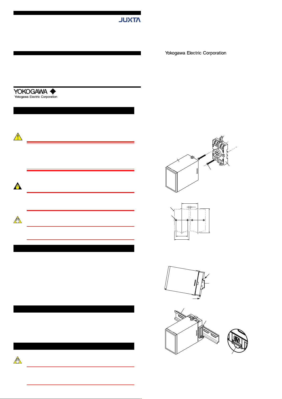
4.1 Wall Mounting
Remove the stoppers (top and bottom) from the product and pull out
the main unit from the socket. Fix the socket on the wall using two M4
screws. Next, insert the main unit into the socket and fasten the main
unit with the stoppers (top and bottom).
This symbol is displayed on the product when it is
necessary to refer to the User’s Manual for information on
personnel and instrument safety. This symbol is displayed
Main unit
in the User’s Manual to indicate precautions for avoiding
danger to the operator, such as an electric shock.
The following symbols are used only in this manual.
IMPORTANT
Indicates that operating the hardware or software in a
particular manner may cause damage or result in a system
failure.
<Mounting Dimensions>
Socket
2-ø4.5 or 2-M4
NOTE
Draws attention to essential information for understanding
the operations and/or functions of the product.
2.
CHECKING PRODUCT SPECIFICATIONS AND PACKAGED ITEMS
(1) Checking the Model and Product Specifications
Check that the model and specifications indicated on the nameplate
attached to the side face of the main unit are as ordered.
4.2 DIN Rail Mounting
Insert a DIN rail into the upper part of the DIN rail groove on the rear of
the socket, and then slide the slide lock at the lower part of the socket
upwards until the socket is fixed into position as shown below.
(2) Packaged Items
Check that the packing carton contains the following items:
● UZ011: 1
● Spacer (used for DIN rail mounting): 1
● External resistor, 1
● User’s Manual (this manual: IM 77J04A01-01E): 1 copy
(Shunt resistor used when 4 to 20mA DC input)
40±0.2
DIN rail
3. GENERAL
This UZ011 is a plug-in type Analog Positioner.
• Internal timer prevent frequent ON-OFF of motor valve.
•
Retransmission output can be used to monitor the motor position value.
• Feedback slide resistance : 100 ⍀ to 10 k⍀
• Easy adjustment operation, ⫾1% Setting Accuracy.
Pitch: 55 or more
5 or more
(51)
Push
Mounting
screws
(85)
Fit into here
DIN rail
Spacer
Stopper
Socket
Unit: mm
Note:
(1) More than 5 mm interval is
required for side-by-side
close mounting.
(2) Use the supplied spacer for
DIN rail mounting to keep 5
mm interval.
(Rear of the socket)
4. MOUNTING METHOD
NOTE
Insert/pull out the main unit into/from the socket vertically
to the face of socket. Otherwise the terminals are bent and
it may cause a bad contact.
Slide lock
4.3 Using a Duct
When using a wiring duct, install the duct at leaset 20 mm away from
the top and bottom faces of the main unit.
Page 2
5. INSTALLATION LOCATIONS
● Avoid the following environments for installation locations:
Areas with vibration, corrosive gases, dust, water, oil, solvents, direct sunlight, radiation, a strong electric field, and/or a strong
magnetic field
● If there is any risk of a surge being induced into the power line
and/or signal lines due to lightning or other factors, a dedicated
lightning arrester should be used as protection for both this unit
and a field-installed device.
6. EXTERNAL WIRING
WARNING
To avoid the risk of an electric shock, turn off the power
supply and use a tester or similar device to ensure that no
power is supplied to a cable to be connected, before carring
out wiring work.
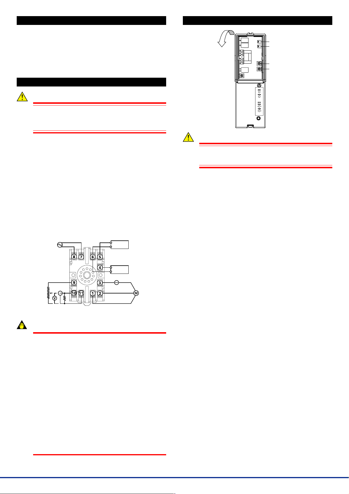
7. ADJUSTMENT
Open
the front panel
(cover)
Zero adjustment
Span adjustment
Dead band adjustment
Timer adjustment
Wiring should be connected to the terminals on the socket of the product. The terminals for external connections are of M3.5 screws. Use
crimp-on terminal lugs for connections to the terminals.
● Recommended cables: A nominal cross-sectional area of 0.5 mm
or thicker for signal cables, and that of 1.25 mm2 or thicker for
power cables.
(1) Position setpoint input signal's terminals are No.5 (⫹) and No.6 (⫺).
(2) Control output signal's terminals are No.1 (H), No.2 (L) and No.3
(COM).
(3) Position feedback input signal's terminals are ;
• When the slide-wire resistance is used: No.9 (100%), No.10
(CTR) and No.11 (0%).
• When analog signal (1 to 5V DC or 4 to 20mA DC) is used: No.10
(⫹) and No.11 (⫺).
(4) Power supply's terminals are No.7 (L⫹) and No.8 (N⫺).
(5) Retransmission output signal's terminals are No.4 (⫹) and No.6 (⫺).
Position setpoint
Power
supply
Position feed back
input
100%
CTR
L+
N-
0%
External resistor
(when 4 to 20mA DC input)
input
+
Control
unit
-
Retransmision
output
+
Monitor
-
COM
L Reverse(0%)
H Direct(100%)
Control
output
IMPORTANT
●
The power line and input/output signal lines should be
installed away from noise-generating sources. Other
wise accuracy cannot be guaranteed.
●
Use of the product ignoring the specifications may
cause overheating or damage. Before turning on the
power, ensure the following:
(a) Power supply voltage and input signal value applied
to the product should meet the required
specifications.
(b) The external wiring to the terminals and wiring to
ground are as specifications.
●
Do not operate the product in the presence of
flammable or explosive gases or vapors. To do so is
highly dangerous.
●
The product is sensitive to static electricity; exercise
care in operating it. Before you operate the product,
touch a nearby metal part to discharge static electricity.
●
Connect the external resistor (shunt resistor) when the
signal of the "Position setpoint input" or the "Feedback
input" is 4 to 20mA DC.
WARNING
2
To avoid electric shock, do NOT touch internal components
when adjusting the instrument with its front panel (cover)
removed.
The product starts running immediately when the power is turned on;
however, it needs 10 to 15 minutes of warm-up before it meets the
specified performance.
7.1 Zero and Span Adjustments
Perform the zero and span adjustments so that 0% and 100% retransmission outputs are obtained. (In general, 0% and 100% outputs are
valve fully-closed and fully-open, respectively.)
7.2 Deadband Adjustment
The deadband is the range (differential in an input signal) until the H
(direct) or L (reverse) relay turns on. Adjust the deadband in the range
from 1 to 20% if an undersired change (disturbance) or hunting adversely affects the operating points. This deadband is adjusted to a
maximum (20%) at the factory before shipment. Adjust the deadband
as narrow as possible (in an appropriate range to minimize outputting a
drive signal) by observing the control line status and stability of motordriven part operations.
7.3 Timer Adjustment
The timer-adjutment time is the time taken to enable the H or L relay
after it has been turned off. That is, it is the time during which a relay
output cannot be issued in order to prevent the motor from being overheated by frequently turning on and off the relays. Thus, there is a certain time until the motor can be restarted. Appropriately adjust the
timer-adjustment time between 1 and 30 seconds such that the relay
does not turn on and off too frequently. The timer-adjustment time is
adjusted to a minimum at the factory before shipment.
2
IM UZ011-01E 2nd Edition June 01,2004-00
 Loading...