

Page 1

User ’s
Manual
UV700G
UV Analyzer
(ORGANIC POLLUTANT MONITOR)
IM 12K01B02-01E
IM 12K01B02-01E
6th Edition
Page 2

INTRODUCTION
This manual describes the operation of the UV700G.
Be sure to read this manual before using the product to ensure proper and safe operation of the
instrument. Also safely store the manual so it is readily available whenever necessary.
Product specications and appearance, as well as the contents of this manual are subject to
change without notice.
n Warranty and Responsibility
Yokogawa warrants that the Product shall be free from defects in material and workmanship and
agrees to repair or replace free of charge, at Yokogawa’s option, any malfunctioned or damaged
Product attributable to Yokogawa’s responsibility for a period of one (1) year from the delivery
unless otherwise agreed with a written agreement. In any one of the following cases, none of the
warranties set forth herein shall be extended;
• Any malfunction or damage attributable to improper operation
• Any malfunction attributable to repair or modication by any person not authorized by
Yokogawa
• Any malfunction or damage attributable to the use in an environment not specied in this
manual
• Any malfunction or damage attributable to violation of the instructions in this manual or
operations in the manner not specied in this manual
• Any malfunction or damage attributable to any cause or causes beyond the reasonable
control of Yokogawa such as natural disasters
• Any deterioration in appearance attributable to corrosion, rust, and so on
• Replacement of consumables
YOKOGAWA SHALL NOT BE LIABLE FOR ANY DAMAGES RESULTING FROM ANY MAL-
FUNCTIONS OF THE PRODUCT, ANY ERASURE OF DATA, OR ANY OTHER USES OF THE
PRODUCT.
<INTRODUCTION>
i
Notes on Handling User’s Manuals
n
• Please hand over the user’s manuals to your end users so that they can keep the user’s
manuals on hand for convenient reference.
• Please read the information thoroughly before using the product.
• The purpose of these user’s manuals is not to warrant that the product is well suited to any
particular purpose but rather to describe the functional details of the product.
• No part of the user’s manuals may be transferred or reproduced without prior written consent from YOKOGAWA.
• YOKOGAWA reserves the right to make improvements in the user’s manuals and product at
any time, without notice or obligation.
• If you have any questions, or you nd mistakes or omissions in the user’s manuals, please
contact our sales representative or your local distributor.
Media No. IM 12K01B02-01E 6th Edition : Feb. 2021 (YK)
All Rights Reserved Copyright © 2007, Yokogawa Electric Corporation
IM 12K01B02-01E
Page 3

ii
<INTRODUCTION>
Safety Precautions
Safety,Protection,andModicationoftheProduct
n
• In order to protect the system controlled by the product and the product itself and ensure
safe operation, observe the safety precautions described in this user’s manual. We assume
no liability for safety if users fail to observe these instructions when operating the product.
• If this instrument is used in a manner not specied in this user’s manual, the protection
provided by this instrument may be impaired.
• If any protection or safety circuit is required for the system controlled by the product or for
the product itself, prepare it separately.
• Be sure to use the spare parts approved by Yokogawa Electric Corporation (hereafter
simply referred to as YOKOGAWA) when replacing parts or consumables.
• Modication of the product is strictly prohibited.
• The following safety symbols are used on the product as well as in this manual.
CAUTION
This symbol gives information essential for understanding the operations and functions.
NOTE
This symbol indicates information that complements the present topic.
Warning and Disclaimer
n
The product is provided on an “as is” basis. YOKOGAWA shall have neither liability nor responsibility to any person or entity with respect to any direct or indirect loss or damage arising from
using the product or any defect of the product that YOKOGAWA can not predict in advance.
IM 12K01B02-01E
Page 4

After-sales Warranty
n Do not modify the product.
n During the warranty period, for repair under warranty consult the local sales representative
or service oce. Yokogawa will replace or repair any damaged parts. Before consulting for
repair under warranty, provide us with the model name and serial number and a description
of the problem. Any diagrams or data explaining the problem would also be appreciated.
• If we replace the product with a new one, we won’t provide you with a repair report.
• Yokogawa warrants the product for the period stated in the pre-purchase quotation Yokoga-
wa shall conduct dened warranty service based on its standard. When the customer site is
located outside of the service area, a fee for dispatching the maintenance engineer will be
charged to the customer.
• Returned goods that have been in contact with process uids must be decontaminated and
disinfected prior to shipment. Goods should carry a certicate to this eect, for the health
and safety of our employees. Material Safety Data sheets must be included for all components of the process to which the sensor have been exposed.
n In the following cases, customer will be charged repair fee regardless of warranty period.
• Failure of components which are out of scope of warranty stated in instruction manual.
• Failure caused by usage of software, hardware or auxiliary equipment, which Yokogawa
Electric did not supply.
• Failure due to improper or insucient maintenance by user.
• Failure due to modication, misuse or outside-of-specications operation which Yokogawa
does not authorize.
• Failure due to power supply (voltage, frequency) being outside specications or abnormal.
• Failure caused by any usage out of scope of recommended usage.
• Any damage from re, earthquake, storms and oods, lightning, disturbances, riots, warfare,
radiation and other natural changes.
n Yokogawa does not warrant conformance with the specic application at the user site.
Yokogawa will not bear direct/indirect responsibility for damage due to a specic application.
<INTRODUCTION>
iii
n Yokogawa Electric will not bear responsibility when the user congures the product into
systems or resells the product.
n Maintenance service and supplying repair parts will be covered for ve years after the pro-
duction ends. For repair for this product, please contact the nearest sales oce described in
this instruction manual.
IM 12K01B02-01E
Page 5

Blank Page
Page 6

<CONTENTS>
UV700G
UV Analyzer
(ORGANIC POLLUTANT MONITOR)
IM12K01B02-01E6thEdition
CONTENTS
INTRODUCTION .............................................................................................i
Safety Precautions .......................................................................................ii
After-sales Warranty ...................................................................................iii
1. Overview .................................................................................................... 1-1
1.1 Introduction ....................................................................................................... 1-1
1.2 Description of Parts .......................................................................................... 1-2
1.2.1 Unit ..................................................................................................... 1-2
1.2.2 Display ............................................................................................... 1-4
v
2. Specication ............................................................................................. 2-1
2.1 StandardSpecication ..................................................................................... 2-1
2.2 Characteristics .................................................................................................. 2-3
2.3 ModelandSuxCodes ................................................................................... 2-4
2.4 OverhaulParts ...................................................................................................2-4
2.5 ExternalDimensionsandFlowDiagrams ...................................................... 2-5
2.6 Connection Diagram ....................................................................................... 2-10
2.7 Measurement Principle .................................................................................. 2-11
3. Installation ................................................................................................. 3-1
3.1 Conditions for Installation ............................................................................... 3-1
3.2 InstallationMethod ...........................................................................................3-2
3.3 Pipingconguration ......................................................................................... 3-4
3.4 Wiring ................................................................................................................. 3-6
3.4.1 Grounding .......................................................................................... 3-6
3.4.2 Power Supply ..................................................................................... 3-6
3.4.3 Connecting Signal Lines .................................................................... 3-6
3.4.4 Connecting Detector to Converter ..................................................... 3-7
3.4.5 Connecting Float Switch Cable of Overow Tank to Converter ........ 3-7
4. Operation ................................................................................................... 4-1
4.1 Preparation for Operation ................................................................................ 4-1
4.2 Starting Operation ............................................................................................ 4-2
4.3 ShuttingDown ................................................................................................... 4-3
4.3.1 For Shut Down within 7 Days ............................................................. 4-3
4.3.2 For Shut Down over 7 Days ............................................................... 4-3
4.4 Restarting Operation ........................................................................................ 4-3
IM 12K01B02-01E
Page 7

vi
<CONTENTS>
4.4.1 For Shut Down within 7 Days ............................................................. 4-3
4.4.2 For Shut Down over 7 Days ............................................................... 4-3
5. Calibration ................................................................................................. 5-1
5.1 Calibration Pattern and its Cycle .................................................................... 5-1
5.2 Notes regarding Calibration ............................................................................ 5-2
5.3 Calibration Screen Display .............................................................................. 5-2
5.4 Calibration of UV/VIS ........................................................................................ 5-3
5.4.1 How to Prepare Calibration Solution.................................................. 5-3
5.4.2 Common Zero Calibration.................................................................. 5-6
5.4.3 Common Span Calibration ................................................................ 5-9
5.4.4 Individual (UV) Span Calibration ...................................................... 5-12
5.5 TURB (turbidity) Span Calibration ................................................................ 5-15
5.5.1 How to Prepare the Calibration Solution ......................................... 5-15
5.5.2 TURB (turbidity) Span Calibration ................................................... 5-16
6. Functions .................................................................................................. 6-1
6.1 MEAS. (Measurement) Screen ......................................................................... 6-1
6.2 TableofFunctions ............................................................................................ 6-1
6.3 Maintenance Screen Display ........................................................................... 6-2
6.4 Maintenance - Setting ....................................................................................... 6-3
6.4.1 Signal Allocation ................................................................................. 6-3
6.4.2 Signal Input Setting ............................................................................ 6-4
6.4.3 Output Setting .................................................................................... 6-5
6.4.4 Output Condition Setting .................................................................... 6-7
6.4.5 Time Adjustment ................................................................................ 6-7
6.4.6 LCD Setting ........................................................................................ 6-8
6.4.7 Touch Panel Adjustment .................................................................... 6-9
6.4.8 Maker Maintenance Mode ................................................................. 6-9
6.5 Maintenance - Measurement Setting ............................................................ 6-10
6.5.1 Measuring Range Setting for each Component .............................. 6-11
6.5.2 Setting of Decimal Place for each Component ................................ 6-12
6.5.3 Unit Setting for UV, VIS, and UV-αVIS ............................................. 6-12
6.5.4 Setting of Turbidity Correction Factor ..............................................6-13
6.5.5 Setting of COD Conversion Factor and Turbidity Correction Factor 6-14
6.5.6 Setting of MAX Alarm Value for COD and TURB (turbidity) ............ 6-15
6.5.7
6.5.8 Unit Setting for TURB (turbidity) ......................................................6-17
6.6 Maintenance - Action ...................................................................................... 6-17
6.6.1 Action ............................................................................................... 6-17
6.7 Maintenance-Check ...................................................................................... 6-18
6.7.1 Unit Information ................................................................................ 6-19
6.7.2 Individual ID Setting ......................................................................... 6-19
6.7.3 External Input/Output Check............................................................ 6-19
Setting of MIN Alarm Value for COD and TURB (turbidity) .................. 6-16
IM 12K01B02-01E
Page 8

<CONTENTS>
6.7.4 Check Analog Input .......................................................................... 6-20
6.7.5 Check Analog Output ....................................................................... 6-21
6.8 DataCheck ....................................................................................................... 6-21
6.8.1 Log Data Check ............................................................................... 6-22
6.8.2 Log Data Deletion ............................................................................ 6-23
6.8.3 Graph Display .................................................................................. 6-24
6.8.4 Calibration Report Check ................................................................. 6-25
6.8.5 Calibration Report Deletion .............................................................. 6-26
6.8.6 CF Card Transfer ............................................................................. 6-27
6.8.7 CF Card Initialization ........................................................................ 6-27
6.9 Alarm ................................................................................................................ 6-28
6.9.1 Alarm Check .................................................................................... 6-29
6.9.2 Alarm Stop ....................................................................................... 6-29
6.9.3 Alarm History Check ........................................................................ 6-30
6.9.4 Alarm History Deletion ..................................................................... 6-30
7. ExternalInputandOutput ....................................................................... 7-1
7.1 Terminal diagram of input and output ............................................................ 7-1
7.2 Analog Output ................................................................................................... 7-2
7.3 Contact Input and Output ................................................................................. 7-3
7.3.1 Contact Output ................................................................................... 7-3
7.3.2 Contact Input ...................................................................................... 7-4
7.4 SavingDatatoaCFCard ................................................................................. 7-5
vii
8 Maintenance .............................................................................................. 8-1
8.1 Maintenance item .............................................................................................. 8-1
8.2 Maintenance of Detector .................................................................................. 8-2
8.2.1 Cleaning Method for Measuring Cell ................................................. 8-2
8.2.2 Replacement of Wiper Blade Rubber ................................................ 8-4
8.2.3 Replacement of Desiccant Agent and Seal Washers for Screws ......8-6
8.2.4 Replacement of Desiccant Agent in the Measuring Cell ................... 8-7
8.3 Cleaning of Sampling Unit ............................................................................. 8-11
8.3.1 Cleaning of Overow Tank and Measuring Tank ............................. 8-11
8.3.2 Removal of Inner Tank of Measuring Tank ...................................... 8-12
8.4 Accessories and spare parts ......................................................................... 8-13
9 Troubleshooting ....................................................................................... 9-1
9.1 Table of Status and Operation ......................................................................... 9-1
9.2 Table of alarm and Operation .......................................................................... 9-1
9.3 Alarm Occurrence Condition ........................................................................... 9-2
9.4 Causes and Measures for Alarm ..................................................................... 9-3
App.1 Overview ............................................................................................ App.1-1
App.1.1 Cautions ..................................................................................................... App.1-1
App.1.2 Composition .............................................................................................. App.1-1
IM 12K01B02-01E
Page 9

viii
<CONTENTS>
App.2 Installation ........................................................................................ App.2-1
App.2.1 Selecting an installation location ........................................................... App.2-1
App.2.2 Cautions for installation environment .................................................... App.2-1
App.2.2.1 Sample water condition ............................................................. App.2-1
App.2.2.2 Surrounding environment .......................................................... App.2-1
App.2.3 Installing UV700G .....................................................................................App.2-1
App.2.3.1 Positions of foundation bolts for pole stand ............................... App.2-1
App.2.3.2 Service and maintenance space ............................................... App.2-2
App.2.3.3 Figure of completed pole stand mount ...................................... App.2-2
App.2.3.4 Pole stand assembly .................................................................. App.2-3
App.2.3.5 Measuring tank assembly .......................................................... App.2-3
App.2.3.6 Overow tank assembly ............................................................. App.2-4
App.2.3.7 Converter assembly ................................................................... App.2-6
App.3 Piping ................................................................................................. App.3-1
App.3.1 Piping procedure ......................................................................................App.3-1
App.4 Wiring ................................................................................................. App.4-1
App.4.1 Wiring procedure ......................................................................................App.4-1
App.4.1.1 Earth connection ........................................................................ App.4-1
App.4.1.2 Power supply ............................................................................. App.4-1
App.4.1.3 Cable connection for detector .................................................... App.4-2
App.4.1.4 Float switch cable connection for overow tank ........................ App.4-2
App.4.1.5 Signal line connection ................................................................ App.4-2
Customer Maintenance Parts List ...................................... CMPL 12K01B02-01E
Revision Information ...............................................................................................i
IM 12K01B02-01E
Page 10

<1. Overview>
1. Overview
1.1 Introduction
GENERAL
Water pollution control laws and regulations require monitoring of wastewater quality to prevent
water pollution in lakes, rivers and enclosed bodies of water. Pollutant load is an index of
water quality standards and is dened as the product of the COD (chemical oxygen demand)
concentration and the wastewater volume. Certain entities are required to measure pollutant
loads and comply with the limits.
Among various methods for COD measurement, automatic ultraviolet absorption spectrometry is
the ideal choice on the whole since it provides high correlation between analyzer and laboratory
results, measurement continuity and maintainability.
The UV700G Ultraviolet (UV) analyzer is an instrument for continuous on-line measurement
using the same cell length modulation method as its predecessor UV400G.
It provides improved operability through a wide measuring range and touch screen interface, high
reliability and excellent maintainability.
1-1
FEATURES
• Graphic LCD with touch screen on the converter provides easy interactive operation.
• Detector uses the rotary cell length modulation method. Zero check is performed at the time
of minimum cell length, virtually eliminating zero drift.
• Continuous cell cleaning with unique wiper system, allowing long term, stable
measurement.
• Analyzer covers a wide measuring range:
from 0-0.1 Abs to 0-5.0 Abs.
• Flow-through cell type for easy maintenance.
• Data memory function for transferring data to a PC via an optional compact ash (CF) card.
IM 12K01B02-01E
Page 11
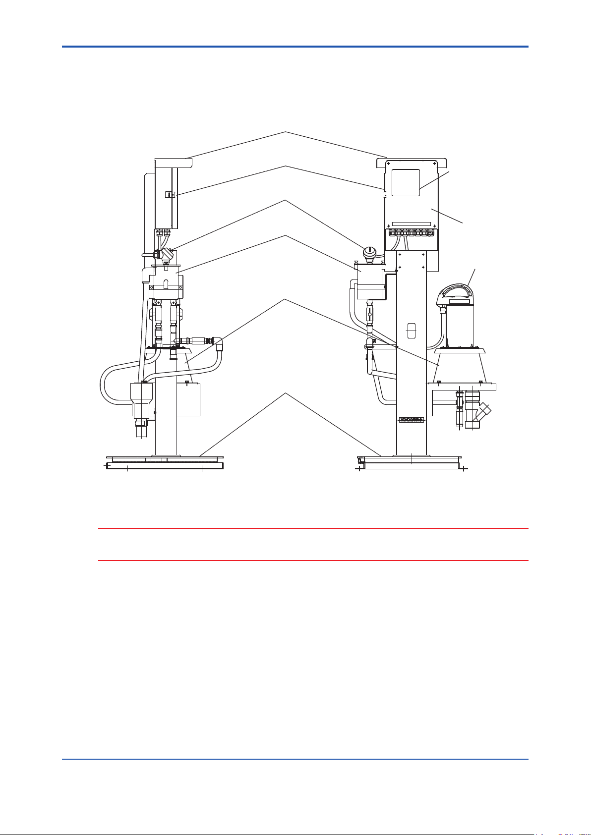
1.2 Description of Parts
1.2.1 Unit
Hood (optional)
Converter
Float Switch
<1. Overview>
1-2
Display
Left Side View
Overflow Tank
Measuring Tank
Base
Door
Detector
Front View
CAUTION
The stanchions illustrated are typical examples. Appearance and size may vary depending on the
specication.
IM 12K01B02-01E
Page 12
<1. Overview>
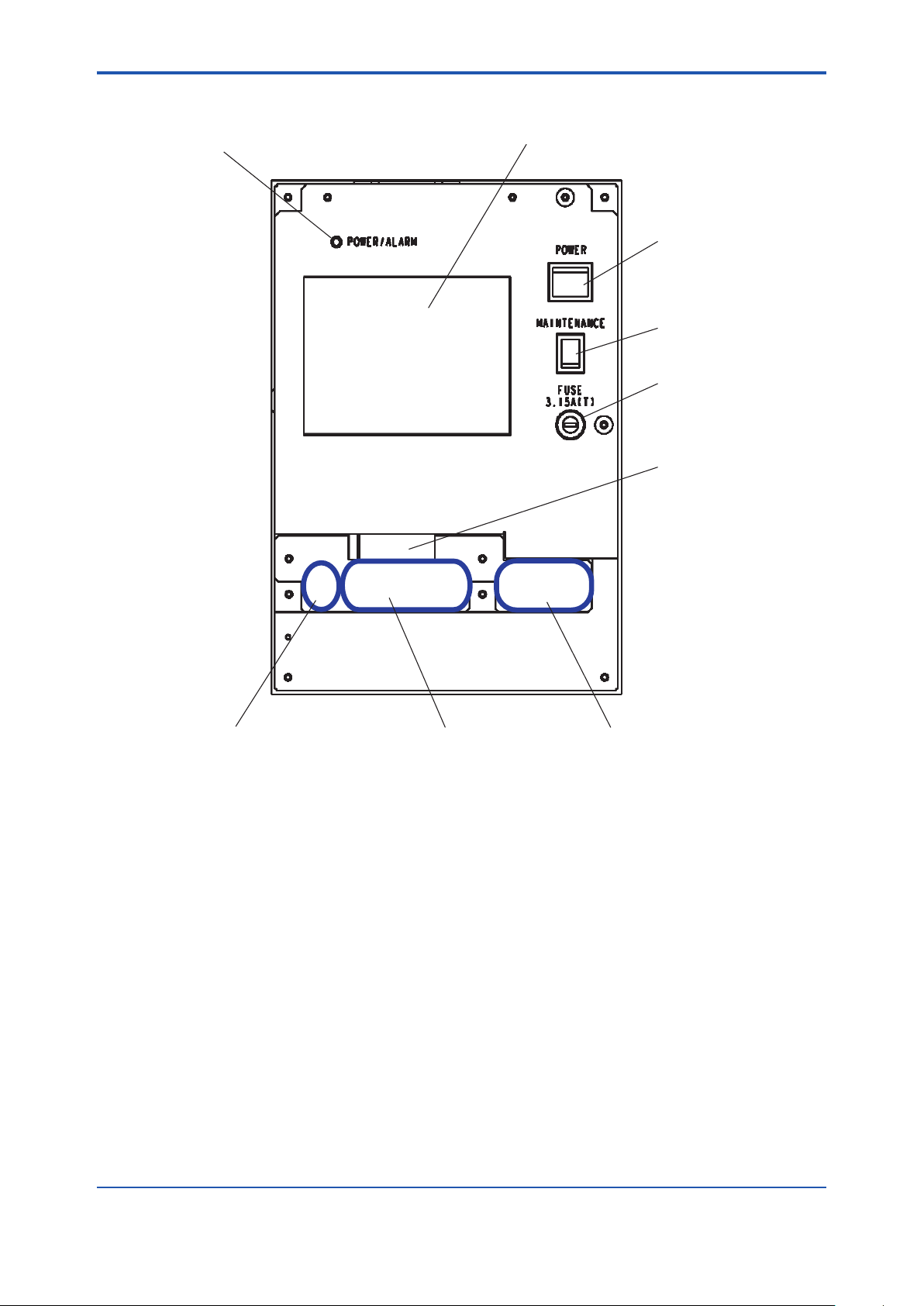
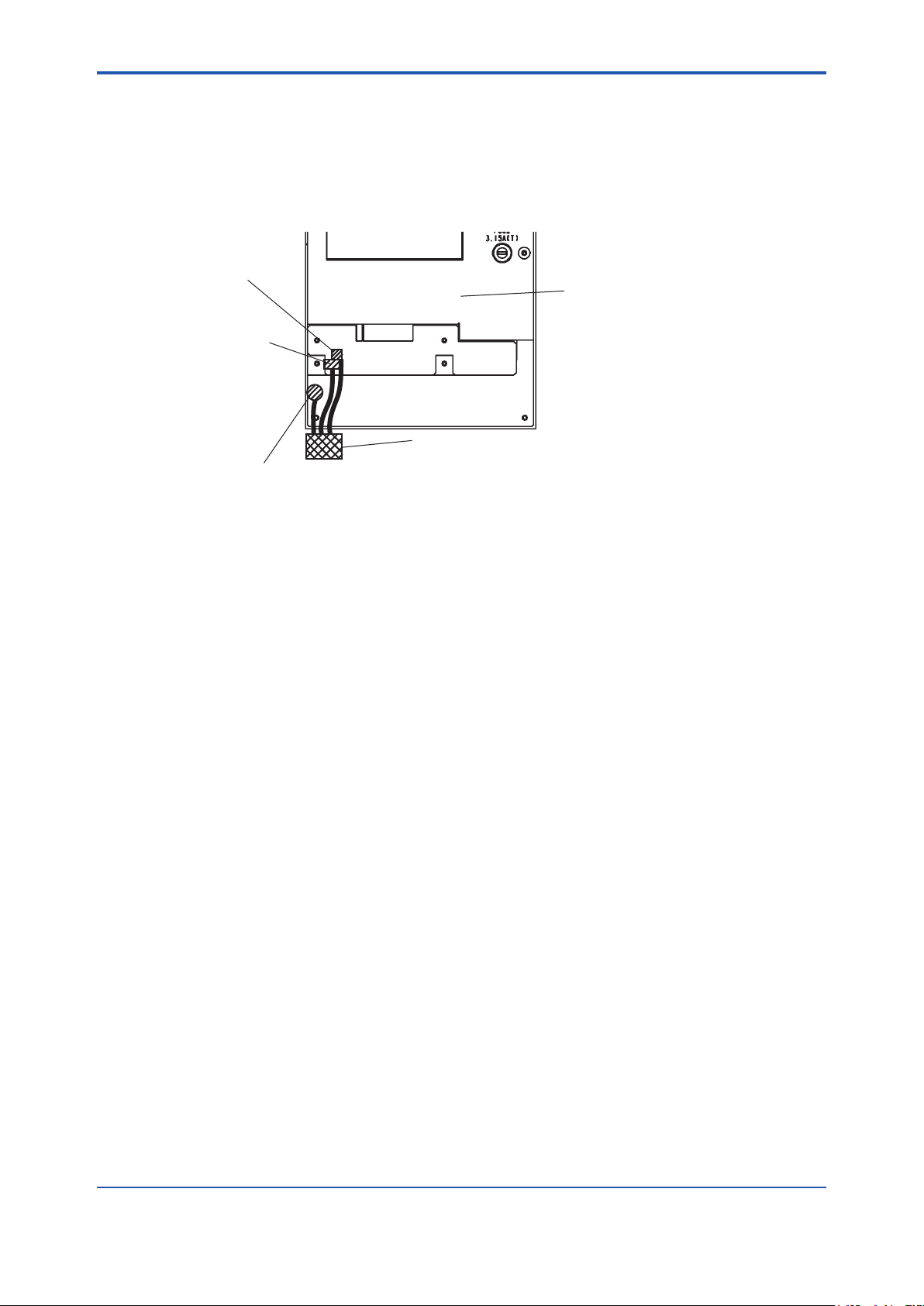
l Insideoftheconverter
1-3
Power / alarm LED
Display (Touch panel)
Power switch
Maintenance switch
Fuse
CF card insertion slot
. CF CARD
Connectors for the detector Signal terminals
AC power terminals
IM 12K01B02-01E
Page 13
<1. Overview>
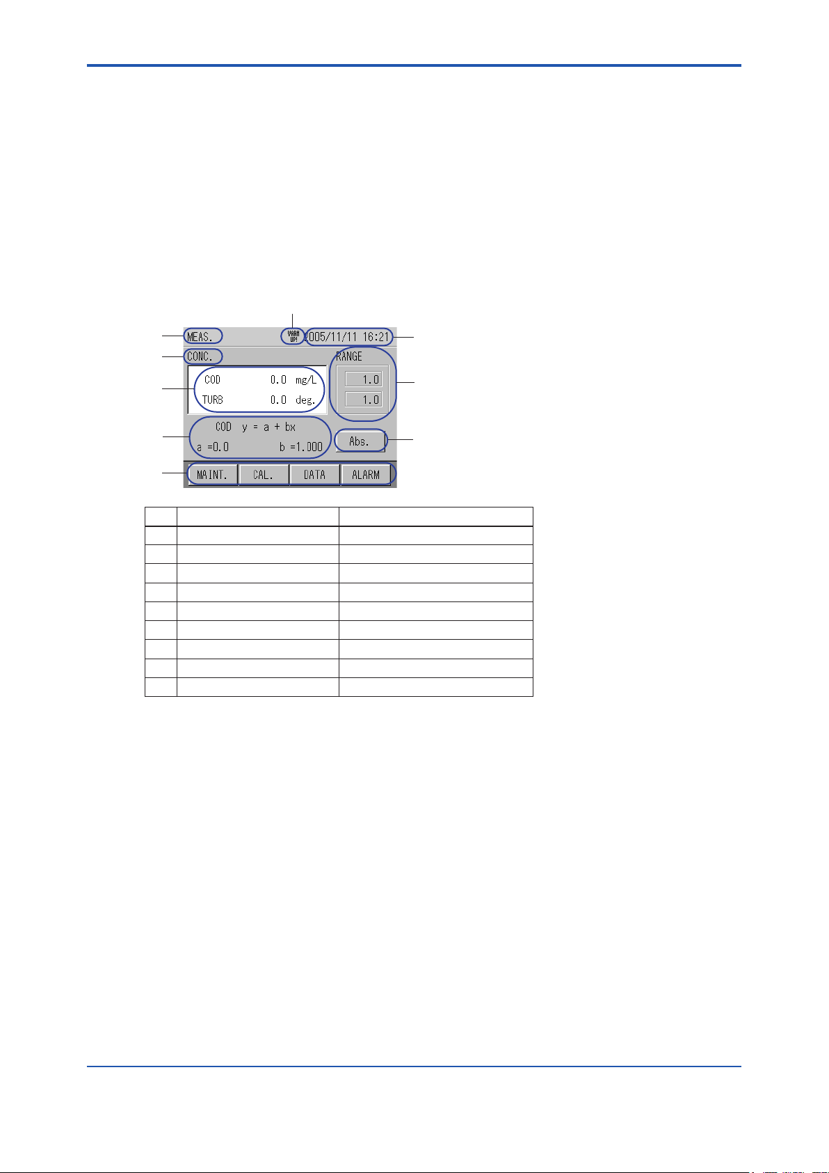
1.2.2 Display
This section describes the parameters shown on a typical display:
• The display is touch panel. Do not press buttons with wet hands, or a sharp object such as a
pen tip or a screwdriver.
• If no buttons are pressed for a certain period of time, the backlight turns OFF.
• If no buttons are pressed for about two hours on displays other than those for measurement,
data or alarm, the display turns to the measurement display.
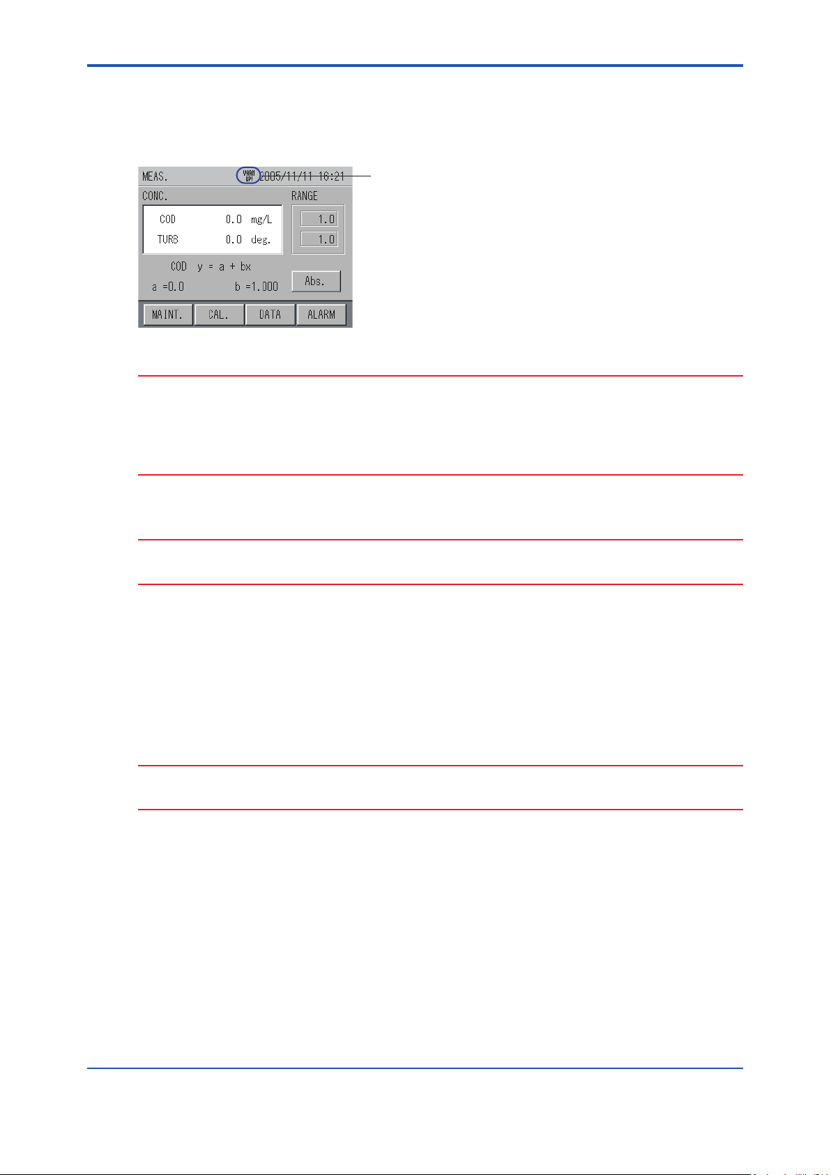
l Exampleofdisplay-Displayingmeasurementreadings
The display shows measurement readings.
7
1-4
1
3
4
5
6
NO. Display exampleDescription
1
2
3
4
5
6
7
8
9
WARM UP!
2
8
9
MEAS., SETTING, LOG DATA, etc.Title of display
2004/01/30 09:57Clock
Abs, CONC, etc.Items to be measured
Instantaneous valuesReadings
Conversion factors for COD, etc.Conversion factor
MAINTENANCE, CAL, etc.Operation buttons
WARM UP!: Unit is being warmed up. Status of unit
RangeRange
Abs, CONC, etc.Switchable measurement items
When the power is turned ON, “WARM UP!” is displayed. This will disappear after one hour.
IM 12K01B02-01E
Page 14
<1. Overview>
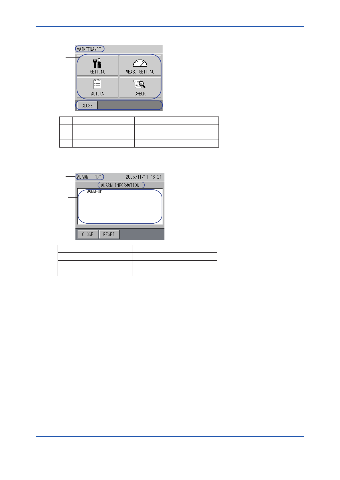
l Exampleofdisplay-Displayingitemstobeselected
1
2
3
NO. Display exampleDescription
1
2
3
MAINTENANCE, SETTING, etc.Title of display
SETTING, MEAS. SETTING, etc.Selection keys
CLOSE etc. Switching keys
l Exampleofdisplay-Displayinghistoryandotherinformation
1
2
1-5
3
NO. Display exampleDescription
1
2
3
Alarm history, calibration report, etc.Title of display
Description of alarms, etc.Items to be displayed
–Data list
IM 12K01B02-01E
Page 15

Blank Page
Page 16

<2.Specication>
2. Specication
2.1 StandardSpecication
Measurement : Organic pollutants in wastewater.
Measurement method:
Dual optical path, dual wavelength, rotary cell length modulation method
Measurement wavelength:
Ultraviolet (UV): 253.7 nm
Visible light (VIS): 546.1 nm
Light source: Low pressure mercury-vapor lamp
Detector: Silicon photo cell, ow-through type
Measuring range (corrected for 10 mm cell)
UV/VIS absorbance 0-0.1 to 0-5.0 Abs
Display: Graphic LCD with touch screen,
320 240 dot, with backlight
Indication: UV absorbance, VIS absorbance, UV- VIS absorbance, COD
concentration, turbidity
Resolution: 0.0001 Abs (factory default) or 0.001 Abs
COD conversion: Conversion equation Y = a bX
where Y = COD concentration
X = absorbance (UV-VIS)
Turbidity conversion: Conversion equation Y = a bX
where Y = turbidity,
X = absorbance(VIS)
Analog output:
Number of outputs: 3
Functions: 3 functions selectable:
UV absorbance / VIS absorbance/ UV-VIS absorbance / COD
concentration / turbidity
Specications: 4-20 mA DC or 0-16 mA DC, isolated
(non-isolated between channels)
Contact output:
Number of outputs: 6
Functions:
2 functions xed:
Power o, maintenance status
4 functions selectable:
Total alarm / COD high alarm / turbidity high alarm / light souse
malfunction / no sample / cleaning motor error / analyzer error
Descriptions:
Power o:
Activated when power o occurs
Maintenance status:
Activated when instrument is in maintenance or calibration mode or
when MAINTENANCE switch is turned on
Total alarm:
Cleaning motor error, light source malfunction and / or analyzer error
2-1
IM 12K01B02-01E
Page 17

<2.Specication>
Specications: Voltage-free contact output, Form A
Contact rating: 0.3 A / 125 V AC, 1A / 30 V DC (resistive load), independent
common at each output
Contact input:
Number of inputs: 2
Functions: No sample oat switch, time adjustment
Specications: Voltage-free contact input (open collector can be connected), isolated
On resistance: 100 V max.
Open circuit voltage: 5.5 V DC
Short circuit current: 5 mA max.
Data memory: Measured data can be stored in converter and stored data transferred to
CF card.
Log interval: 1 min or 1 hour
Log time: On the hour every hour
Retention time: Approx. 10 days for 1 min interval
Approx. 1 year for 1 hour interval
Calibration method: Manual calibration using zero / span standard (calibration solution in
ampoule) (One touch calibration is available)
Cleaning method: Automatic, continuous wiper cleaning
Operating conditions:
Ambient temperature: 0 to 40 8C
Ambient humidity: 90% RH or less
Installation location: Flat, stable place not subject to severe vibration or shock. Allow pace for
maintenance. No dust, mist, corrosive gases are present. Atmospheric
pressure. Avoid exposure to direct sunlight. Good ventilation. Max.
altitude of 2000 m.
Sample conditions:
Temperature: 2 to 40 8C (non-freezing)
Pressure: 20 to 500 kPa
pH: 4 to 10
Flow rate: 2 to 20 L/min
Concentration of suspended solids:
200 mg/L or less
Note: Protection against freezing should be provided when needed.
Piping connection:
Analyzer with pole-base mount type (UV700G-A-A)
Sample inlet: Rp 1/2 female
Bypass outlet: Rc 1/2
Overow outlet 1: 13A nominal, elbow tting
Overow outlet 2: 20A nominal, elbow tting
Drain port: Rc 1/2
Discharge port: 50A nominal, tube tting
Analyzer with standard self-supporting type (UV700G-hB-A)
Sample inlet: Rp 1/2 female
Drain port: Rc 1/2
Discharge port 1: 50A nominal, tube tting
Discharge port 2: VP40 pipe
2-2
IM 12K01B02-01E
Page 18

<2.Specication>
Wiring:
Power wiring:
Size: 1.25 mm2 (AWG16) or larger
Connection: M4 screw terminal
Termination: Crimp terminal for M4 screw
Signal wiring:
Size: 0.08 to 1.5 mm2 (AWG28 to 16)
Connection: Pin terminal
Termination: Strip 7 mm of insulation o wire end
Dimensions (excluding projections):
Converter: 240(W) 3 104(D) 3 320(H) mm
Detector: 200(W) 3 180(D) 3 403(H) mm
Materials (main materials):
Wetted parts: SUS304, R-PVC, fused silica, polypropylene, chloroprene rubber,
titanium (when option code “/TN” is specied)
Stanchion
Material:
Pole-base mount type (UV700G-hA-A):
Iron
Standard self-supporting type (UV700G-hB-A):
Carbon steel plate
Finish:
Converter: Epoxy with modied melamine resin, baked, Munsell 5PB8/1 equivalent
Pole-base mount type (UV700G-hA-A):
Epoxy with modied melamine resin, baked, Munsell N1.0 equivalent
Standard self-supporting type (UV700G-hB-A):
Polyurethane resin, baked, Munsell 0.6GY3.1/2.0 equivalent
Construction: Outdoor installation (equivalent to IP54)
Weight:
Converter: Approx. 5.0 kg
Detector: Approx. 5.6 kg
Pole-base mount type:
Approx. 31 kg
Standard self-supporting type (including converter, detector, overow tank):
Approx. 47 kg
Power supply: 100 to 230 V AC 610%, 50/60 Hz
Grounding: JIS Class D grounding (100 V or less, φ1.6 mm copper wire)
Power consumption: 100 to 120 V AC, 45 VA max.
200 to 230 V AC, 60 VA max.
2-3
2.2 Characteristics
Linearity: 62% FS (65% FS for 2.6 to 5.0 Abs)
Repeatability: 62% FS (65% FS for 2.6 to 5.0 Abs)
Stability: 62% FS/24 h (65% FS/24 h for 2.6 to 5.0 Abs)
Response time: 90% within 1 min (sample ow rate at 5 L/min)
IM 12K01B02-01E
Page 19
<2.Specication>
2.3 ModelandSuxCodes
2-4
Model
UV700G - - - - - - - - - - - - - - - - - - - -
Language
Stanchion
/
Option
*1: Should be selected when sample water contains seawater or chlorine.
Sux
Code
-J
-E
N
A
B
Option Code Description
UV analyzer (organic pollutant analyzer)
- - - - - - - - - - -
- - - - - - - - - - -
- - - - - - - - - - -
- - - - - - - - - - -
- - - - - - - - - - -
- - - - - - - - - - -
-A
/H
/TN
Japanese
English
Without stanchion
Pole-base mount type
Standard self-supporting type2
Always -A
Hood for sun protection
Titanium wetted parts*1
See “8.4 Accessories and spare parts” regarding Standard Accessories and Auxiliary parts.
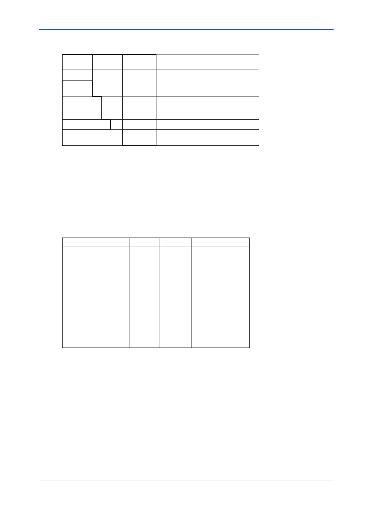
2.4 OverhaulParts
For one year after delivery no parts are required to be replaced except wiper blade rubbers and
desiccants. To ensure reliable measurement with simple routine maintenance, it is recommended
that the instrument be overhauled every year by Yokogawa. The table below lists parts required
for overhaul.
Item P/N Qty Description
Inspection parts kit K9436CA 1 set
Contents:
V-ring A
Seal washer
Seal washer
Roller
Cell packing 2
Desiccant (cell)
Wiper blade rubber
Light source
Desiccant (detector)
Stepping motor
Blind cap
Case packing
Note: For yearly overhaul, it is recommended that an inspection parts kit (P/N K9436CA) be purchased.
The kit does not include calibration solutions, which should be purchased separately.
K9430EP
K9436CB
K9430ES
K9430EN
K9430ER
K9430EH
K9436CG
K9436FY
K9430EG
K9436GB
K9436GR
K9436GK
2 pcs/set
4 pcs/set
10 pieces
6 pieces
4 pcs/set
2 pcs/set
4 pcs/set
1 piece
5 pcs/set
1 piece
4 pcs/set
1 piece
Cell
Detector’s upper case
Cell
Cell
Cell
Cell
Cell
Cell
Cell
Detector
Detector, case
Detector, case
IM 12K01B02-01E
Page 20
<2.Specication>
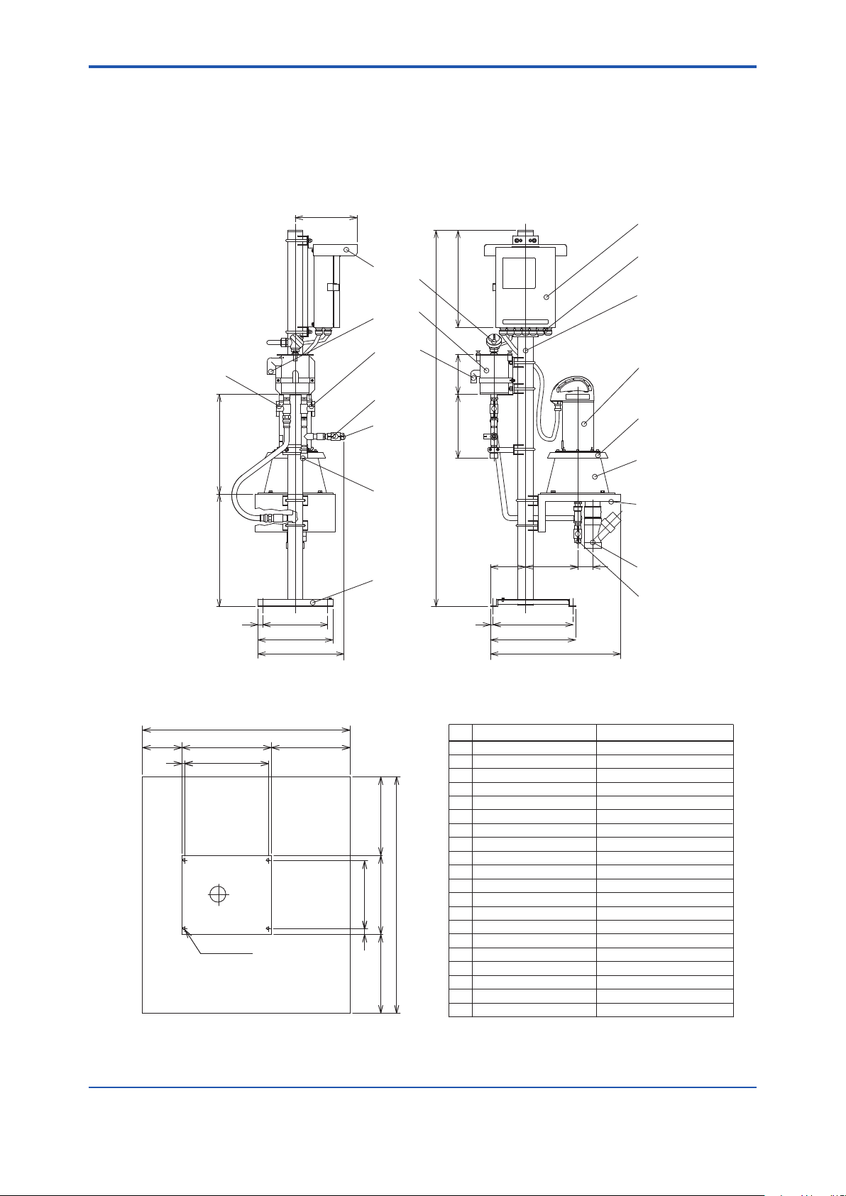
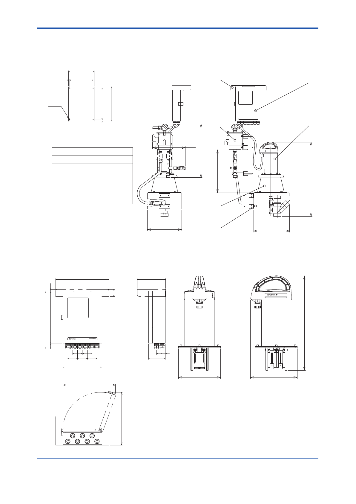
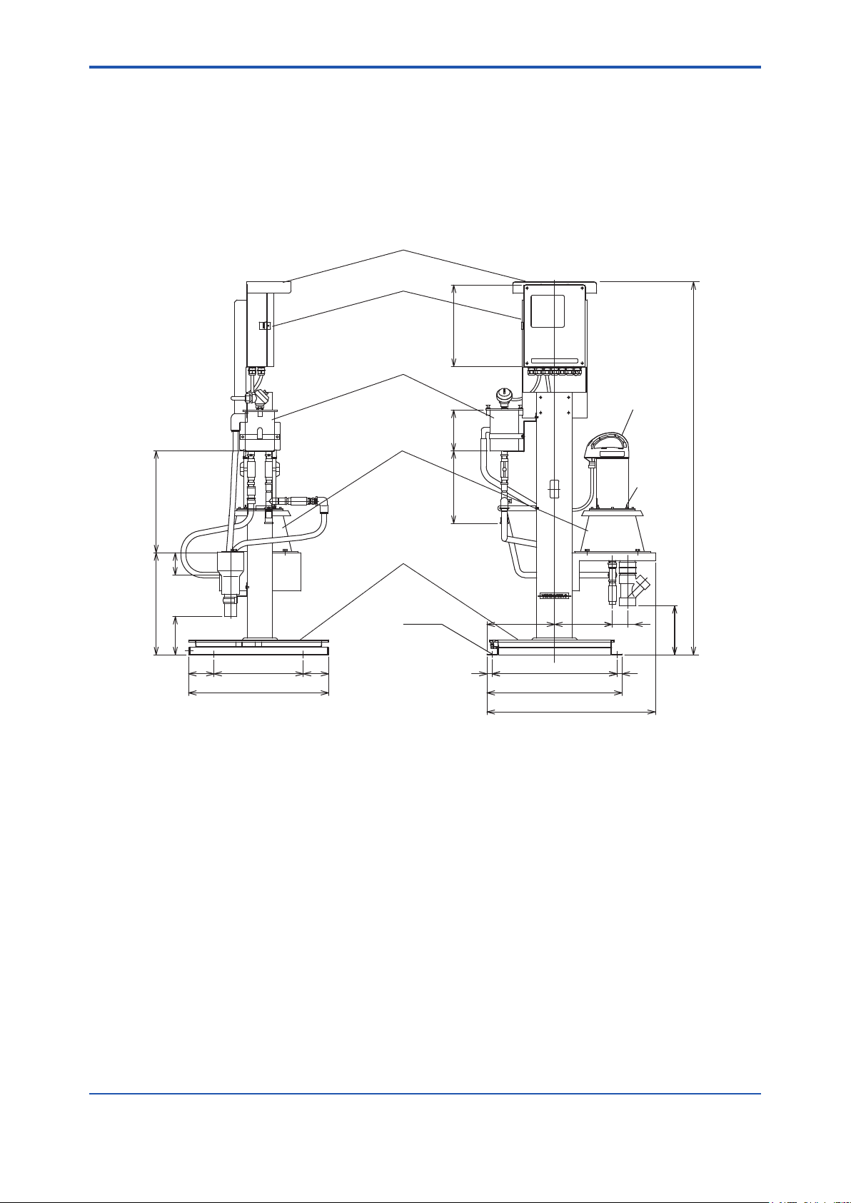
2.5 ExternalDimensionsandFlowDiagrams
1. UVAnalyzerwithpole-basemounttype,UV700G-A-A
n ExternalDimensions Unit: mm
2-5
18
400350-500
)(248
1
2
*
20
16
19
4
17
8
(390)
3
5
(160)(285)
9
10
(1506)
11
12
13
15
140
(209)
(60)
14
7
6
20
260
300
(345)
10
320
340
(520)
* Hood for sun protection is optionally available.
1840
340
32010
42-ø9
M8
Maintenance Area
Front
Basic Anchor Bolt Plan
(1000)500
300 (1000)1000
26020
2300
Weight: Approx. 31 kg
No.
1
2 Wiring port
3 Pole
4 Overflow tank
5 Detector
6 Drain port (V-4)
7 Discharge port 50A nominal, tube fitting
8 Ball valve (V-1)
9 Ball valve (V-2)
10
11
12
13
14
15
16
17
18
19
20
Item Description
Converter
Rc 1/2
Bypass outlet Rc 1/2
Blind plate
Measuring tank
Sample inlet Rp 1/2 female
Detector table
Base
Overflow outlet 2 20A nominal, elbow fitting
Overflow outlet 1 13A nominal, elbow fitting
Ball valve (V-3)
Float switch
OptionalHood for sun protection
IM 12K01B02-01E
Page 21
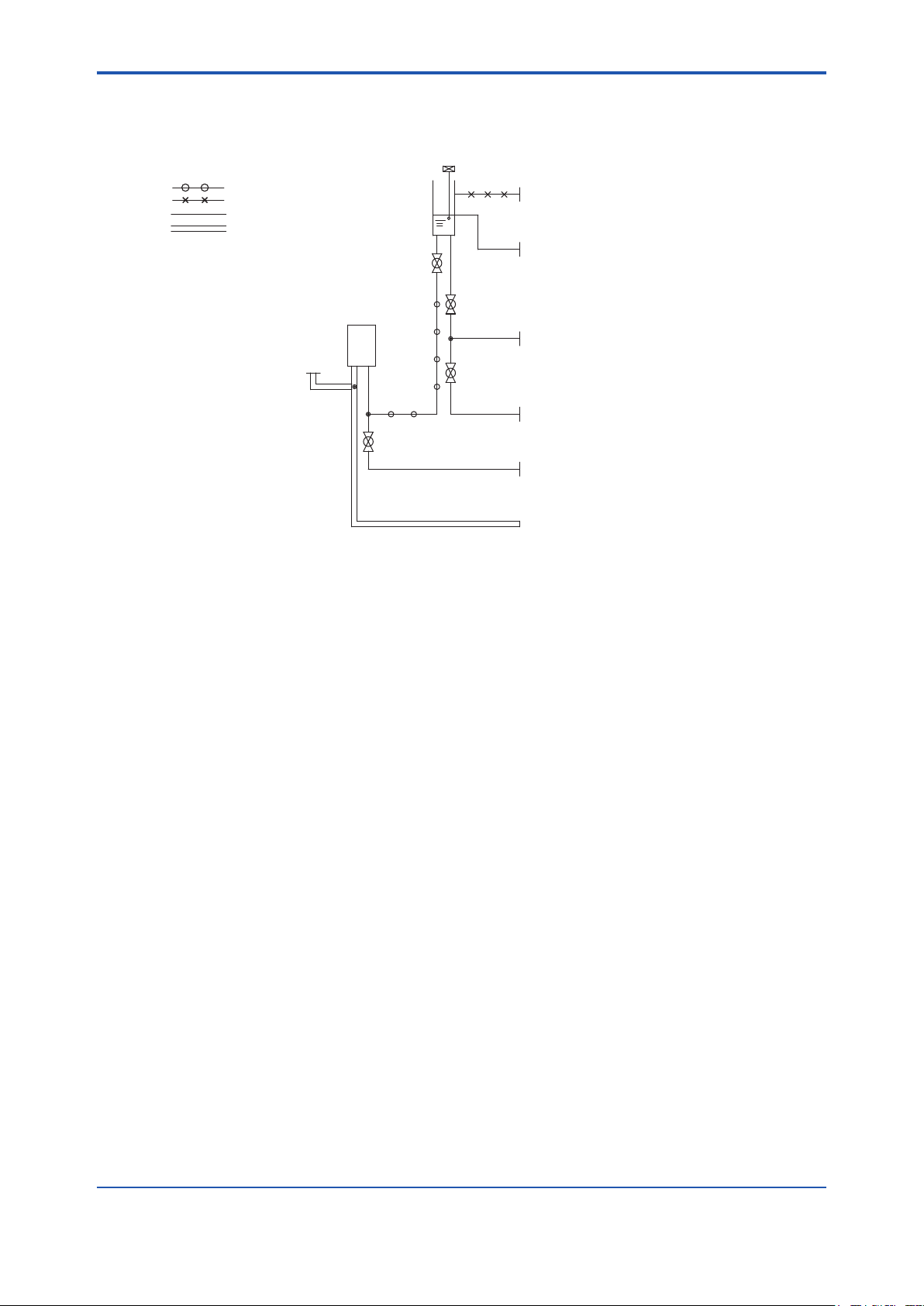
<2.Specication>
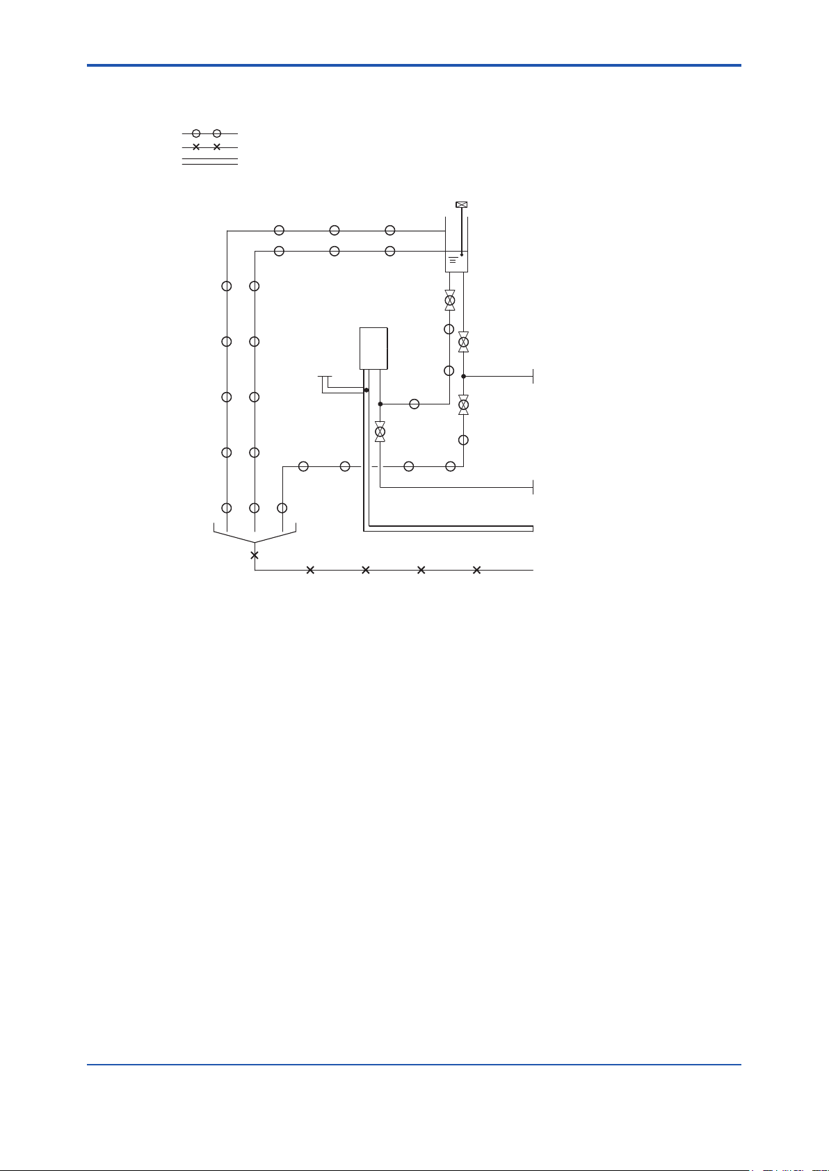
n FlowDiagram
Overflow Tank
Float Switch
Piping Material
ø22/ø15 soft tube
VP20 rigid PVC pipe
VP13 rigid PVC pipe
VP50 rigid PVC pipe
V-3
Overflow Outlet 2
20A nominal, elbow fitting
Overflow Outlet 1
13A nominal, elbow fitting
2-6
Measuring Tank
Vent to Atmosphere
V-1
Sample Inlet
Rp 1/2 female
V-2
Bypass Outlet
Rc 1/2
V-4
Drain Port
Rc 1/2
Discharge Port
50A nominal, tube fitting
Note: Drain piping should be installed so that back pressure does not develop.
IM 12K01B02-01E
Page 22
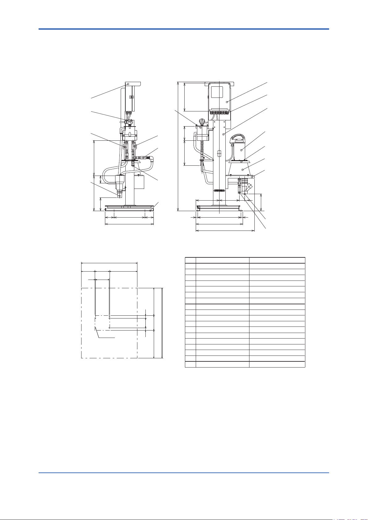
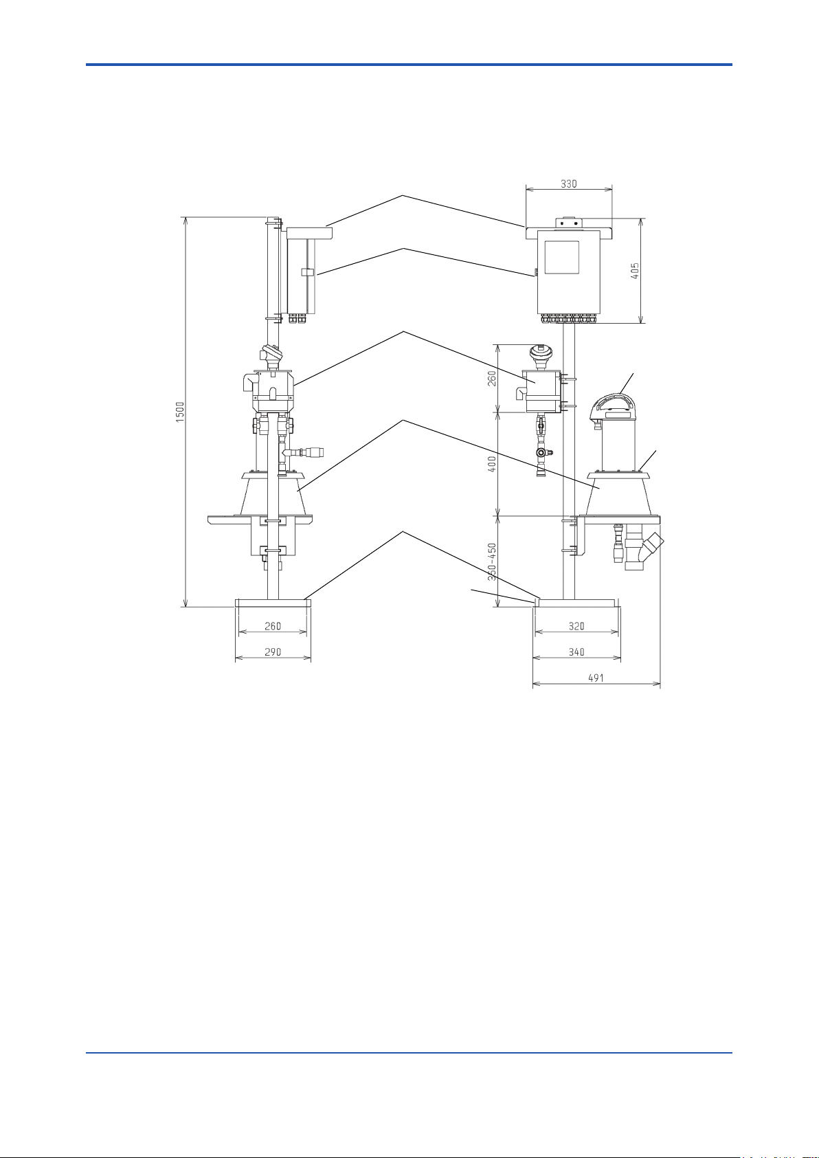
<2.Specication>
2. UVAnalyzerwithstandardself-supportingtype,UV700G-B-A
n ExternalDimensions Unit: mm
1
2-7
*
18
17
9
8
10
400
87
16
400
150
100
350 (100)
550
13
15
* Hood for sun protection is optionally available.
2030
530 (1000)500
49020
350 9595
540 (1000)1000
2540
2–ø15
4
Front
Maintenance Area
320
4
(160)
1464
(285)
(240)
(265)
49020
530
(60)
665
Weight: Approx. 47 kg
No.
1 Converter
2 Wiring port
3 Stanchion
4
5 Detector
6 Drain port (V-4)
7 Discharge port 1
8 Ball valve (V-1)
9 Ball valve (V-2)
10
11 Blind plate
12 Measuring tank
13 Sample inlet Rp 1/2 female
14 Detector table
15 Base
16
17
18
Item Description
Overflow tank
Ball valve (V-3)
Float switch
Hood for sun protection
2
3
5
11
12
14
(192)
(20)
7
6
Rc 1/2
50A nominal, tube fitting
VP40 pipeDischarge port 2
Optional
IM 12K01B02-01E
Page 23
<2.Specication>
n FlowDiagram
Piping Material
ø22/ø15 soft tube
VP40 rigid PVC pipe
VP50 rigid PVC pipe
Float Switch
Overflow Tank
V-3
Measuring Tank
V-1
2-8
Vent to Atmosphere
Sample Inlet
Rp 1/2 female
V-2
V-4
Drain Port
Rc 1/2
Discharge Port 1
50A nominal, tube fitting
Discharge Port 2
VP40 pipe
Note: Drain piping should be installed so that back pressure does not develop.
IM 12K01B02-01E
Page 24
<2.Specication>
3. UVAnalyzerwithoutstanchion,UV700G-N-A
n ExternalDimensions
240
21511.5
6
2-9
1
4-M6
Converter
Rear
29512.5
320
Converter Mounting Dimensions
No. Item
1 Converter
2
Detector
3
Measuring tank
4
Detector table
5
Overflow tank
Hood for sun protection(optional)
6
Pipes, fittings, and U-bolts are included
with shipment.
320
When "UV700G-N-A" is specified, each assembly will be
delivered without a stanchion and converter brackets that are
provided when "UV700G-A-A" is specified. Hood for sun
protection is optionally available.
Converter
330
12.5
45
175
5
(307.5)
(500)
Head ≥400
3
4
Detector
2
(690)
(333)
UV700GULTRA VIOLET ANALYZER
320
354.5
(34.5)
ULTRA VIOLET
UV
ANALYZER
6060
60 6060
240
Maintenance Area ≥500
104
Converter Dimensions
Maintenance Area ≥500
Weight: Approx. 5.0 kg
403±5
20
35
200±3180
Detector Dimensions
Weight: Approx. 5.6 kg
IM 12K01B02-01E
Page 25
<2.Specication>
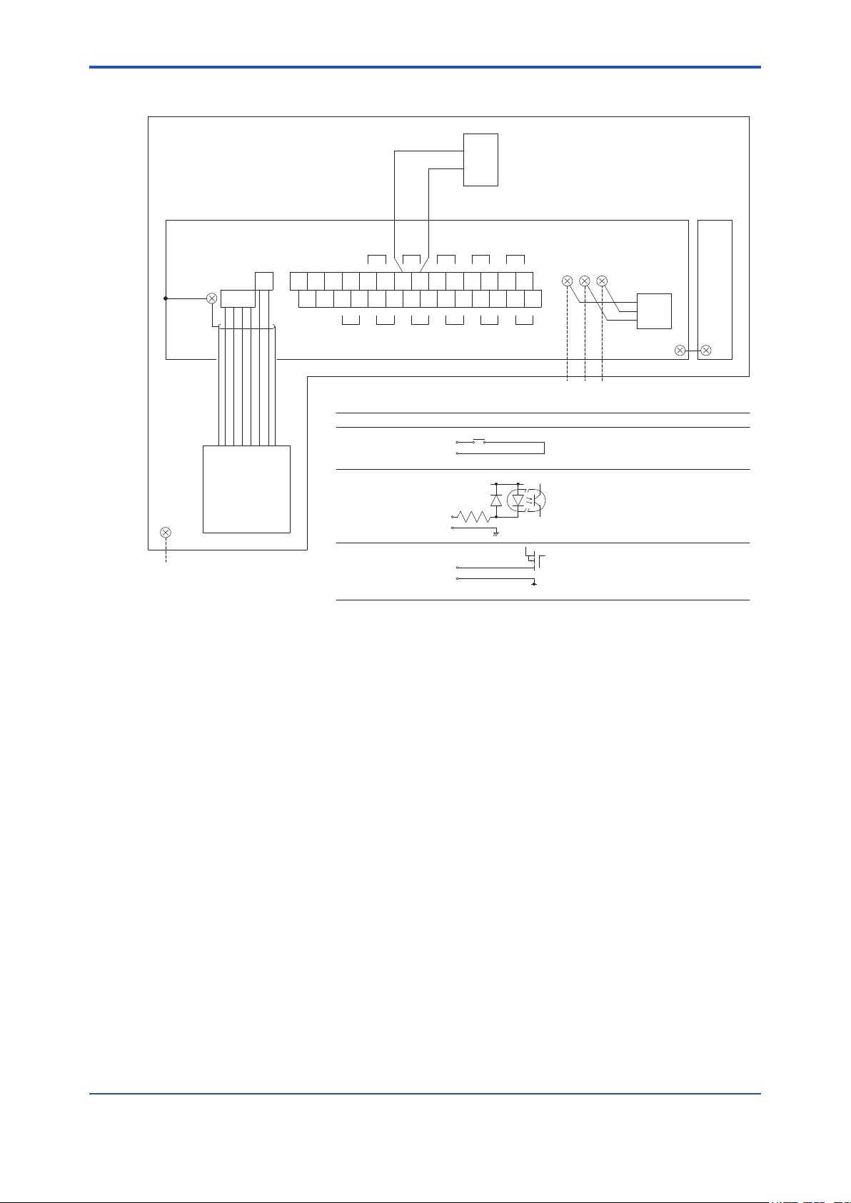
0-16/4-20 mA DC
Current signal output
Isolated input (shared common)
Load resistance 600 V max.
Voltage free contact signal input
Isolated input (shared negative)
On resistance: 100 V max.
Open circuit voltage: 5.5 V DC
Short circuit current: 5 mA max.
Contact rating:
0.3 A/125 V AC, 1A/30 V DC (resistive load)
Voltage free contact signal output
SpecificationI/O Circuit
Analog signal output
Contact signal input
Contact signal output
Signal Type
2
1
COM
Photocoupler
15V
470V
1 2 3 4 5 6 7 8 9 10 11 12 13 14
15 16 17 18 19 20 21 22 23 24 25 26 27 28
1 2
Analog
Output 1
Analog
Output 3
Contact
Input 2
Contact
Output 2
Contact
Output 4
Contact Output 6
(maintenance status)
Analog
Output 2
Contact
Input 1
Contact
Output 1
Contact
Output 3
Contact Output 5
(power off)
O-6O-4O-2I-2A-3A-1
A-2 I-1 O-1 O-3 O-5
Empty
Terminal
Internal Connections
(Not for Use)
CN2
4-pin Connector
CN1
2-pin Connector
Detector
M3 Shield
Ring Terminal
Dedicated Cables
L E N
100-230 V AC 610%,
50/60 Hz, 60 VA max.
Power Supply
33M4 Ring Terminals
1
2EArrester
Converter
(Chassis)
Converter
(Door)
Float Switch
M5
Ground Bolt
Class D Grounding
Stanchion
2 1
1
2
1
2
1
2
1
2
1
2
1
2
1
2
1
2
1
2
2
1
2.6 Connection Diagram
2-10
IM 12K01B02-01E
Page 26
<2.Specication>
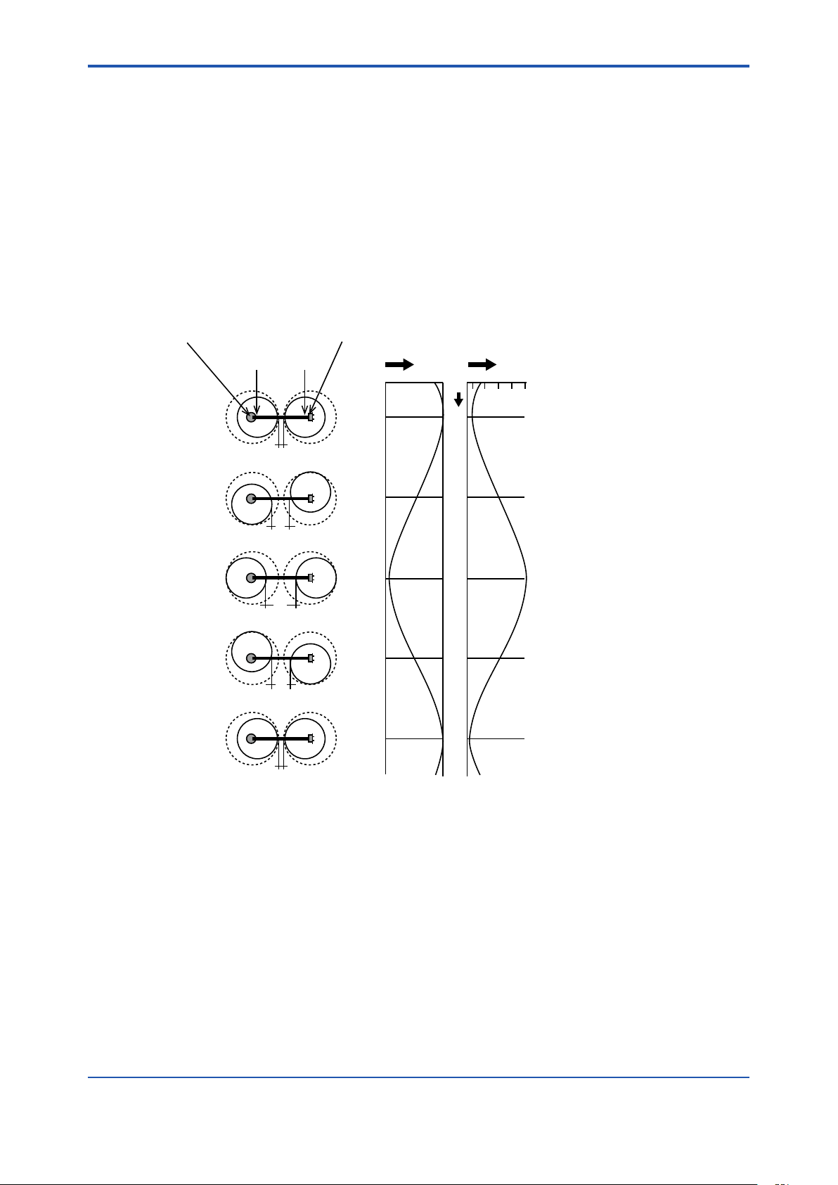
2.7 Measurement Principle
The rotary cell length modulation method, which combines high performance and reliability, is
adopted in this unit.
Two cylinder cells are placed, arranged with the light source and detector in a position where they
are decentered from the center of cylinder as shown in the gure below. By rotating these two
cylinder cells with the centers of the light source and detector as the rotation center, the distance
between the 2 cylinders (cell length) is modulated continuously and periodically. The signal input
to the detector from the light source is the signal which changes the dierence in light intensity
between the maximum cell length (θ = 180 degrees) and the minimum cell length (θ = 0 degree)
into the amplitude. Wide range measurement becomes possible by selecting the optimum cell
length and calculating according to the change of cell length.
2-11
Rotation center of decentered cell
Center of light source
Center of cylinder cell
θ=0°
L1
θ=90°
L2
θ=180°
L3
θ=270°
L2
Rotation center of decentered cell
Center of detector
Output signal Cell length
L1 L3
θ
0°
90°
180°
270°
θ=360°
L1
360°
l Optical compensation
Optical compensation is attained by the rotary cell length modulation method. Information
required for optical compensation is the change of light intensity due to the light source, detector,
contamination of the measuring cell etc. This change in light intensity information can be obtained
by monitoring the light intensity when at the minimum cell length (θ = 0 degree).
l Turbidity compensation (TURB)
This unit can measure ultraviolet (UV) and visible light (VIS) absorbances independently. UVαVIS display is possible by setting the turbidity correction factor (α), thus a more reliable turbidity
compensation can be performed.
IM 12K01B02-01E
Page 27

<2.Specication>
a=Y - bX
b=
=
S(X
i
- X)
2
nSXiY
i
- (
SX
i
)(
SY
i
)
(X
i
- X)(Yi - Y)
nSX
i
2
- (
SX
i
)
2
l TURB (turbidity) Measurement
TURB measurement is performed by using the visible light (VIS) absorbance.
The measurement method is the transmitting absorption method.
Calibration with the standard solution enables a simple measurement of TURB.
Measure in the measurement range of 200 deg. or below. If measuring in a measurement range
that exceeds the specied value, the linearity deteriorates due to the scattering light inuence.
l HowtoCalculatetheCODConversionFactor
If it is judged that there is obviously a linear function between the measurement concentration
Xi (i = 1, 2, ...n) and corresponding manual analysis value Yi (i = 1, 2, ...n), the calibration curve
formula (regression formula) is expressed as follows:
Y = a + bX
The gradient of this regression line X-axis (b) and the Y-axis segment (b) can be calculated by
using the measurement value and the least-square method as in the following formula.
2-12
“a” and “b” are rounded to a value which is larger by 1 digit according to the number of signicant
gures of the measurement value.
IM 12K01B02-01E
Page 28

<3. Installation>
3. Installation
3.1 Conditions for Installation
• The unit is weather-proofed for outdoor installation; however, do not install the unit in places
subject to direct sunlight.
• Install the unit near the water sampling point.
• Install the unit where a water-supply system, drainage facilities and a power supply are
provided.
• Install the unit in a place that is well ventilated, free from dirt or dust, and where no corrosive
gases will be generated.
• Install the unit in a place that is free from strong vibration or ferromagnetic elds.
• Install the unit where enough space is provided for conducting routine inspections and
maintenance.
• Secure the unit using anchor bolts.
• Install the unit where enough space is provided for conducting services.
3-1
IM 12K01B02-01E
Page 29
<3. Installation>
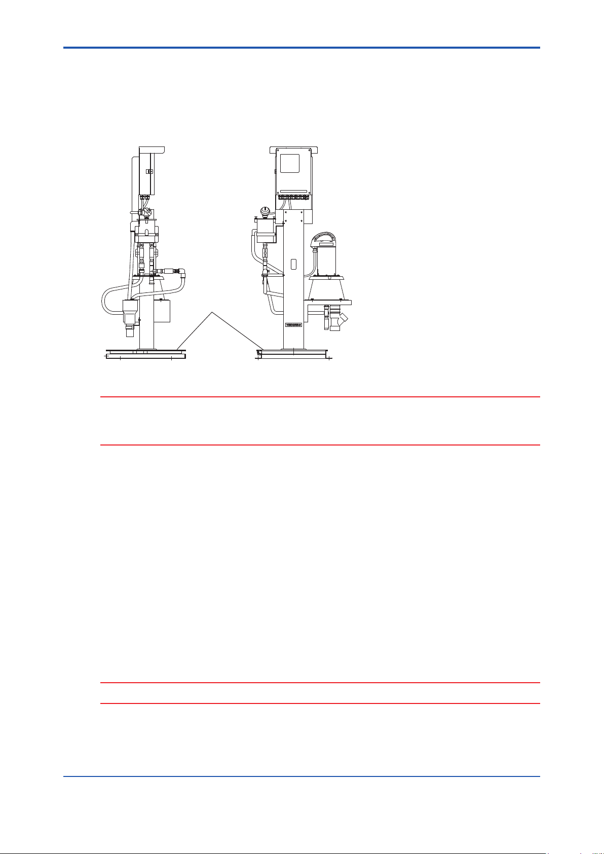
3.2 InstallationMethod
1. UVAnalyzerwithstandardself-supportingtype,UV700G-B-A
• Secure the base with the reference bolts.
• Refer to 3.3 and 3.4 for piping and wring.
Hood (optional)
Converter
320
Overflow tank
Detector
3-2
Unit: mm
400
400
87
150
100
350 (100)
550
Measuring tank
Base
4 - ø15
(160)
(285)
(265)
49020
530
665
(240)
Wing nuts
1464
(4 points)
(60)
(192)
(20)
IM 12K01B02-01E
Page 30
<3. Installation>
2. UVAnalyzerwithPole-basemounttype,UV700G-A-A
• Assemble the base, measuring tank, overow tank and converter as guided in the Appendix.
• Secure the base with the reference bolts.
Hood (optional)
Converter
Overflow tank
Detector
Measuring tank
3-3
Unit: mm
Wing nuts
(4 points)
Base
Secure with M8 bolts
(4 points)
IM 12K01B02-01E
Page 31

<3. Installation>
3.3 Pipingconguration
• Insulate the unit to protect against frozen pipes in the cold weather.
• Drain piping should be as short as possible in order not to create the backpressure. Make
the drain cock discharge the air in order to prevent water from being blocked (rising pipes
cannot be used).
• Diameters of piping sockets
Piping description Diameterofpipingsockets
1 Sample inlet Rp 1/2 female
2 Bypass outlet Rc 1/2 female
3 Overow outlet (1) Elbow tting, 13 dia. (nominal)
4 Overow outlet (2) Elbow tting, 20 dia. (nominal)
5 Drain outlet Rc 1/2 female
6 Discharge Tube coupling, 50 dia. (nominal)
4
Overflow tank
Measuring cell
V-1
Overflow line (2)
Overflow line (1)
3
3-4
Air release
6
Discharge line
V-3
V-4
5
Drain line
V-2
2
Bypass line
Sampling pump
Sample line
1
• Refer to the table below for the diameter for piping
Piping description Diameterofpiping(whenhardPVCpipingisused)
1 Sample lines Nominal diameter is 13 or larger
2 Bypass line Nominal diameter is 13 or larger
3 Overow line (1) Nominal diameter is 13 or larger
4 Overow line (2) Nominal diameter is 20 or larger
5 Drain line Nominal diameter is 13 or larger
6 Discharge line Nominal diameter is 50 or larger
IM 12K01B02-01E
Page 32

<3. Installation>
CAUTION
• Each piping diameter above is determined to go with the respective piping sockets of the
UV700G. If the measuring unit is installed in an area far from the water sampling point and
drainage point, each piping diameter should be larger than that indicated above.
• Ensure that the waste water piping, overow piping (1) and (2), and drain piping have
sucient gradient to allow drainage from the outlet of each pipe. Ensure that the end of
each piping is not immersed in water.
• When using soft PVC piping, use the braid reinforced exible PVC (pressure-resistant) type.
• It is useful to use removable pipe tubing for regular cleaning.
3-5
IM 12K01B02-01E
Page 33
<3. Installation>
3.4 Wiring
3.4.1 Grounding
• Class D grouding (ground resistance 100 V or less) should be performed.
• Make sure to ground to the grounding bolt.
Position of grounding bolt
3-6
CAUTION
• The pole stand and base illustrated are typical examples Appearance and size may vary
depending on specications.
• Make sure to perform grounding of the installed unit to prevent electric shock.
3.4.2 Power Supply
• Connect the power cord to the power source according to “2.6 Connection Diagram”.
• Use a power cable of size 1.25 mm2 (AWG16) or larger.
• Connect a surge absorber or noise killer in parallel to the power line in order to prevent
electric power noise.
3.4.3 Connecting Signal Lines
• Connect the signal lines according to the signal table.
• Use double shield cables for current output signal lines. The shield should be grounded at
the receiver.
• Connect a surge absorber or noise killer in parallel to the contact output signal line in order
to prevent electric power noise.
CAUTION
Never connect the power line to the signal line wiring. It may cause the unit malfunction.
IM 12K01B02-01E
Page 34
<3. Installation>
3.4.4 Connecting Detector to Converter
• Run the cable connectors of detector through the cable clamps at the lower left of converter
case.
• Connect the connectors of the detector to CN1 and CN2 at the lower left of converter case.
• Securely fasten the round terminal of shield line, with a screw (M3), to the screw hole under
the connections CN1 and CN2.
CN1
2-pin connector
Converter
CN2
4-pin connector
Detector cables
Securely fasten the round terminal of shield line, with a screw (M3).
3-7
3.4.5 ConnectingFloatSwitchCableofOverowTankto
Converter
• Run the oat switch cables of the overow tank through the cable clamps at the lower left of
converter case.
• Connect the cables to the terminals No.7 and 8 at the lower center of converter inside.
IM 12K01B02-01E
Page 35

Blank Page
Page 36

<4.Operation >
Inner tank of measuring tank
4. Operation
4.1 Preparation for Operation
1. Ensure that the unit is installed properly according to “3 Installation”.
2. Remove the lid of the overow tank.
3. Remove the detector if the unit is already set to the measuring tank.
CAUTION
When removing from the measuring tank, put the detector on a at surface to prevent it from
falling. It is recommendable to put the detector on the calibration tank for safe and easy handling.
4. Operate the valves as instructed in the ow sheet and dimensional outline drawing:
V-1 and V-4: close all (CLOSE)
V-2 and V-3: open all (OPEN)
5. Supply 2 L/min to 20 L/min of sample water from the underwater pump or the header.
4-1
6. Open valve (V-1) gradually until sample water runs out of the overow outlet (1) of overow
tank. If the sample water does not run out of the overow outlet (1) even when the valve (V-
1) is fully opened, then close valve (V-2) gradually to adjust the ow from the overow outlet
(1).
7. Ensure that sample water overows from the 2 upper notches of the inner tank of measuring
tank and is discharged from the drain outlet.
8. When outlet ow from the overow tank and the inner tank of measuring tank reaches the
designated volume and keeps running consistently, attach the lid of the overow tank and
detector.
9. Make sure that the cables of detector and converter are securely connected.
10. Set the switches of control panel as follows:
POWER switch: OFF
Maintenance switch: ON
IM 12K01B02-01E
Page 37
<4. Operation>
4.2 Starting Operation
1. Turn the POWER switch ON.
The MEAS. screen appears after a while.
“WARM UP!” is indicated.
CAUTION
When the power is turned ON, the motor for detector wipers starts operation at low speed. Some
noises and vibrations may be generated when the motor starts. Note that this normal, and does
not mean any malfunction of the unit.
“WARM UP!” continues to be indicated until the measured values become stable (for about 60
minutes).
4-2
CAUTION
Never touch the cell or directly view the UV lamp of the detector when you check the unit
operation.
2. Set the clock.
Refer to “6.4.5 Time Adjustment”
3. Change the setting as necessary.
Refer to “6 Functions”
4. Calibrate the unit.
CAUTION
Calibration should be performed after the measured value becomes stable. Before the
calibration, perform the running-in operation for an hour or more using the sample water.
Refer to “5 calibration”
Complete the procedure for the preparation of operation. The measurement starts.
5. Turn OFF the maintenance switch.
IM 12K01B02-01E
Page 38

<4.Operation >
4.3 ShuttingDown
4.3.1 ForShutDownwithin7Days
1. Turn ON the maintenance switch.
2. Turn OFF the POWER switch.
4.3.2 ForShutDownover7Days
1. Close all the valves (V-1 to V-4).
2. Turn ON the maintenance switch.
3. Turn OFF the POWER switch.
4. Clean the overow tank and measuring tank.
Refer to “6.6 Maintenance-Action”
5. Clean the cell of converter.
Refer to “3.3 Piping conguration”
4.4 Restarting Operation
4-3
4.4.1 ForShutDownwithin7Days
Follow the procedure of “4.2 Starting Operation”.
4.4.2 ForShutDownover7Days
1. Follow the procedure of “4.1 Preparation for Operation”.
2. Follow the procedure of “4.2 Starting Operation”.
IM 12K01B02-01E
Page 39

Blank Page
Page 40
<5. Calibration>
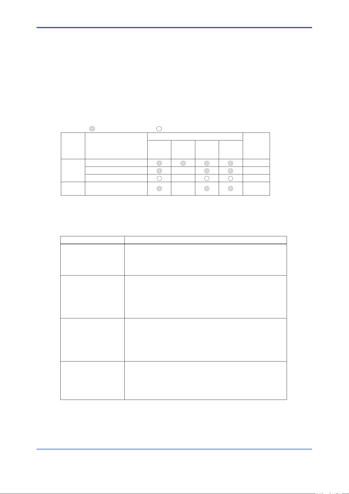
Measuring
item
Calibration pattern
Targeted calibration cycle
Before
operation
Every
week
Every
month
When
problems
occur
Procedure
Reference
UV/VIS
Common zero calibration 5.4.2
Common span calibration 5.4.3
Individual (UV) span calibration
5.4.4
TURB
(turbidity)
Span calibration 5.5.2
—
—
—
: Recommended cycle, : Calibration as necessary – : Unnecessary
5. Calibration
Calibration is the adjustment so that the value indicated by the unit corresponds to the actual
value. It is necessary to obtain measurements of high accuracy and maintain the performance of
the unit.
5.1 Calibration Pattern and its Cycle
It is necessary to perform the calibration periodically.
Perform calibration by following the cycle shown below.
5-1
Perform the calibration in the order of “Common zero calibration,” “Common span calibration,”
(“Individual (UV) span calibration” as necessary), and “TURB Span calibration.”
l DescriptionsforeachCalibration
DescriptionCalibration
Common zero calibration of UV/VIS using the zero calibration solution
Common zero calibration
Common span calibration
Individual (UV) span
calibration
Span calibration
(distilled watter).
Put the zero calibration solution in the calibration tank. After the
measurement value has stabilized, perform calibration by operating the zero
button.
Common span calibration of UV/VIS using the exclusive common span
calibration solution. Put the span calibration solution in the calibration tank.
After setting the calibration value of UV/VIS and the measurement has
stabilized, perform calibration by operating the span button.
If performing either one of calibrations, set the span calibration value to "0"
for the component that is not being calibrated. By doing this, the span
calibration for one component becomes possible.
Individual span calibration of UV using the acid potassium phthalate
standard solution (standard solution for UV calibration).
Put the individual span calibration solution in the calibration tank. After
setting the calibration value of UV and the measurement has stabilized,
perform calibration by operating the span button.
Make sure to set the span calibration value of VIS to "0" before performing
the calibration.
Span calibration of turbidity using the span calibration solution.
Zero calibration is not required is not required as the common zero
calibration for UV/VIS is performed.
Put the span calibration solution for turbidity in the calibration tank. After
setting the calibration value of TURB (turbidity) and the measurement has
stabilized, perform calibration by operating the span button.
IM 12K01B02-01E
Page 41

<5. Calibration>
[CAL.]
l AbouttheCalibrationCoecient
DescriptionCalibration coefficient
Zero calibration coefficient
Span calibration coefficient
Indicates misalignment of zero point
Indicates the gradient of sensitivity
5.2 Notes regarding Calibration
• Perform the calibration in the order of “Common zero calibration,” “Common span
calibration,” and “TURB Span calibration.”
• If the calibration coecient exceeds the specied range during the calibration, an error
occurs and the calibration value is not updated. The previous calibration value remains.
• Use distilled water for the common zero calibration solution. If a solution other than distilled
water is used, the measurement error becomes larger in the low concentration range (0.1
Abs to 0.5 Abs).
If the ion-exchanged water is used, the measurement error also becomes larger.
• Whenever diluting the span calibration solution, make sure to dilute by adding distilled
water.
• When disposing of the common span calibration solution, follow the rules and regulations in
your country / area. As the solution is colored, we recommend disposing of it by diluting with
tap water unless otherwise specied.
• Store the common span calibration solution ampoule in a dark and cold place.
• Use the common span calibration solution ampoule immediately after opening.
• Never ingest the common span calibration solution ampoule or its contents.
• If the common span calibration solution comes into contact with clothes, the clothes may be
stained.
• Never reuse the calibration solution. If the solution is altered, an accurate calibration may
not be obtained.
• Prepare the span calibration solution by following the description in this manual.
5-2
5.3 Calibration Screen Display
1. Press [CAL.] on the MEAS. screen (main screen).
The CALIBRATION screen that shows the calibration menu is displayed.
IM 12K01B02-01E
Page 42

<5. Calibration>
2. Press the measurement items to be calibrated on the CALIBRATION screen.
The CALIBRATION screen for each measurement item is displayed.
Example when the calibration item is UV/VIS:
Calibration item
[UV/VIS]
3. Perform calibration by following the calibration procedure for each measurement item.
5.4 Calibration of UV/VIS
There are three kinds of calibration method for UV/VIS: common zero calibration, common span
calibration, and individual span calibration.
Refer to “5.1 Calibration Pattern and its Cycle”
5-3
5.4.1 How to Prepare Calibration Solution
Use distilled water for the zero calibration solution, and exclusive calibration solution for the
common span calibration solution.
The calibration solution ampoule (H calibration solution (blue label)) for 1 Abs
(100 m-1) is attached to this unit. An attached calibration solution ampoule covers the
measurement range up to 1 Abs. Full scale can be covered from 0.1 Abs to 5.0 Abs (10 m-1 to
500 m-1) by using the 2 or 4 calibration solution ampoules.
Select the measurement full scale you use from the following, and compound the calibration
solution.
Calibration solution
H calibration
solution (blue label)
0 to 1 Abs for
calibration
Measurement full
scale range
0.1 Abs to 1.0 Abs
-1
to 100 m-1)
(10 m
1.1 Abs to 2.5 Abs
-1
to 250 m-1)
(110 m
2.6 Abs to 5.0 Abs
-1
to 500 m-1)
(260 m
Also, our calibration solution ampoule (H II calibration solution (green label)) for 2 Abs (200 m-1)
is also available. If using in the measurement full scale of 1.1 Abs (110 m-1) or over, it is more
economical to buy H II calibration solution ampoules as the number of ampoules used is fewer.
Calibration solution
H II calibration solution
(green label)
0 to 2 Abs
for calibration
Measurement full
scale range
1.1 Abs to 2.5 Abs
-1
to 250 m-1)
(110 m
2.6 Abs to 5.0 Abs
-1
to 500 m-1)
(260 m
Qty. of calibration
solution ampoule
1
2
4
Qty. of calibration
solution ampoule
1
2
Concentration of calibration
solution when diluted with 2 L
UV: 0.690 Abs (69.0 m-1)
VIS: 0.880 Abs (85.0 m-1)
UV: 1.380 Abs (138.0 m-1)
VIS: 1.760 Abs (170.0 m-1)
UV: 2.760 Abs (276.0 m
VIS: 3.520 Abs (340.0 m
Concentration of calibration
solution when diluted with 2 L
UV: 1.380 Abs (138.0 m-1)
VIS: 1.760 Abs (170.0 m-1)
UV: 2.760 Abs (276.0 m-1)
VIS: 3.520 Abs (340.0 m-1)
-1
)
-1
)
l Common zero calibration solution
Preparation:
Distilled water: 2 L
Make sure to use the distilled water.
IM 12K01B02-01E
Page 43

<5. Calibration>
l How to prepare common span calibration solution
Preparation:
Calibration solution ampoule: 1 to 4
Zero solution (distilled water): approximately 3 L
2 L Measuring ask: 1
Cleaning bottle: 1
1. Drain the solution remaining in the top of ampoule to the bottom part.
Drain the solution remaining in the top of the ampoule
as much as possible by flicking with a finger.
2. Make a cut line on the ampoule with a cutter knife, knife of other sharp object.
5-4
Make a cut line all the way around the ampoule.
3. Break the ampoule.
Hold the ampoule and break off the top part.
Be careful not to spill the solution.
Hold the bottom part of ampoule on the table.
4. Pour the contents from the ampoule into a 2 L measuring ask that was cleaned using zero
solution in advance.
Squeeze the ampoule several times.
5. Pour the zero solution up to the gauge line of 2 L measuring ask, and dissolve the solution
IM 12K01B02-01E
Cleaning bottle
Dissolve the solution left in the ampoule
by adding zero solution, and pour into
the measuring flask. (Repeat 2 or 3 times.)
Also dissolve the solution left in the top of
ampoule by adding zero solution, and pour
into the measuring flask.
by shaking thoroughly.
Page 44

<5. Calibration>
CAUTION
• Make sure to use distilled water to dilute the span calibration solution. Never use the tap
water, groundwater, or industrial water.
• Use 2 ampoules of H calibration solution when preparing the span calibration solution of 1.1
Abs to 2.5 Abs (110 m-1 to 250 m-1). In this case, the concentration value of span calibration
solution is double the concentration value described on the ampoule.
• Use 4 ampoules of H calibration solution or 2 ampoules of H II calibration solution when
preparing the span calibration solution of 2.6 Abs to 5.0 Abs (260 m-1 to 500 m-1). In this
case, the concentration value of span calibration solution is 4 times the concentration value
described on the ampoule for H calibration solution, and double the H II calibration solution
ampoule.
l Howtopreparespancalibrationsolutionofacidpotassiumphthalatestandard
solution (standard solution for UV calibration)
Normally calibration with the common span calibration solution is available; also, UV calibration
with acid potassium phthalate is possible.
Preparation:
Acid potassium phthalate: using the special grade chemicals, dried for 1 hour at a
temperature of 120 8C, and cooled in desiccators
Zero solution (distilled water): approximately 3 L
1L Beaker: 1
2L Measuring ask: 1
Electronic balance: 1 (accuracy shall be within 1 mg)
Cleaning bottle: 1
1. Determine the requirement of acid potassium phthalate from the following table according to
the measurement range.
5-5
UV measurement
range
0.1 Abs to 0.5 Abs
(10 m-1 to 50 m-1)
0.6 Abs to 1.0 Abs
(60 m-1 to 100 m-1)
1.1 Abs to 2.5 Abs
(110 m-1 to 250 m-1)
2.6 Abs to 5.0 Abs
(260 m-1 to 500 m-1)
Requirement of
acid potassium
phthalate when
compounded in
2 L
100 mg 50 mg/L
200 mg 100 mg/L
400 mg 200 mg/L
800 mg 400 mg/L
Concentration
of span
calibration
solution
Light absorption
when the
temperature of
calibration
solution is 25 8C
(absorption factor)
0.44 Abs
(44 m-1)
0.87 Abs
(87 m-1)
1.74 Abs
(174 m-1)
3.48 Abs
(348 m-1)
Light absorption
when the
temperature of
calibration
solution is 20 8C
(absorption factor)
0.43 Abs
(43 m-1)
0.85 Abs
(85 m-1)
1.70 Abs
(170 m-1)
3.40 Abs
(340 m-1)
Light absorption
when the
temperature of
calibration
solution is 30 8C
(absorption factor)
0.45 Abs
(45 m-1)
0.89 Abs
(89 m-1)
1.78 Abs
(178 m-1)
3.56 Abs
(356 m-1)
CAUTION
The calibration solution of acid potassium phthalate has a temperature characteristic. The
temperature characteristic is (4.5 3 10-3) Abs/ 8C at a temperature of 5 8C to 30 8C. Measure the
temperature of calibration solution to calculate the light absorption during calibration.
Calculation method:
Light absorption of calibration solution = Light absorption of calibration solution at a temperature
of 25 8C 3 (1 + (temperature of calibration solution - 25) 3 0.0045)
(The above table shows light absorptions also at 20 8C and 30 8C as a reference.)
IM 12K01B02-01E
Page 45

<5. Calibration>
Calibration item
[UV/VIS]
Pour the tap water to a depth of approximately 9 cm
(so that the base of the detector imay not soak in the water).
2. Measure the requirement of acid potassium phthalate (special grade chemicals) following
the table above.
3. Pour approximately 500 mL of the zero solution (distilled water) into the 1 L beaker, and add
the measured acid potassium phthalate to dissolve thoroughly.
NOTE
The acid potassium phthalate dissolves easily when setting the temperature of the zero solution
from 40 8C to 50 8C.
4. Pour the solution in the 1 L beaker into the 2 L measuring ask, add zero solution to the
gauge line, and shake to dissolve the solution.
5.4.2 Common Zero Calibration
[CAL.] [UV/VIS]
5-6
MEAS. screen
Refer to “5.3 Calibration Screen Display”
CALIBRATION screen
UV/VIS CAL. screen
• Preparation
Plastic bucket: 1 (diameter: approximately 30 cm)
Zero solution (distilled water): approximately 3 L
Calibration tank: 1
2 L Measuring ask: 1
Cleaning bottle: 1
• Calibration procedure
1. Press [UV/VIS] on the CALIBRATION screen of converter.
2. Clean the attached calibration tank with zero solution thoroughly, and pour the zero solution
to the scale.
3. Prepare the plastic bucket and pour the tap water.
4. Remove the detector from the measurement tank.
CAUTION
• When removing the detector, make sure not to lose wing nuts.
• As the UV lamp is illuminated, work with an eye protector. The UV lamp should not be
viewed directly as your eyes may be damaged.
IM 12K01B02-01E
Page 46

<5. Calibration>
Dip the cell unit in the water and shake it from side to side
and up and down to remove contamination.
Clean the cell unit using the zero solution in the cleaning bottle.
Allow the solution to adhere by shaking from side to side
for several times.
[X.XX]
5. Clean the cell unit of the detector.
• If there is any extraneous matter around the cell, remove it.
• Next, dip the cell unit in the plastic bucket to remove contamination.
• Clean the cell unit using the zero solution in the cleaning bottle again.
• If the cell unit is contaminated heavily, clean the cell unit by referring to “8.2.1 Cleaning
Method for Measuring Cell”
5-7
CAUTION
Do not spill any solution on the base of the cell rotary shaft (V-ring seal part).
6. After cleaning the cell unit, dip the cell in the calibration tank.
7. Press the button for [ZERO VALUE] for UV on the UV/VIS CAL. screen.
The screen changes to the UV ZERO screen.
8. Enter “0” with numeric keypad, and press [SET],
Input range: 0.000 Abs to 5.000 Abs or 0.0 m-1 to 500.0 m
The screen returns to the UV/VIS CAL. screen.
-1
NOTE
[CLEAR]: Cleans all input numeric values.
[BACK]: Cleans the rightmost number.
IM 12K01B02-01E
Page 47

<5. Calibration>
CAUTION
The decimal place of input range varies according to the setting in “6.5.2 Setting of Decimal Place
for each Component”
9. Press the button for [ZERO VALUE] for VIS on the UV/VIS CAL. screen.
10. Enter “0” with numeric keypad, and press [SET].
Input range: 0.000 Abs to 5.000 Abs or 0.0m-1 to 500.0m
The screen returns to the UV/VIS CAL. screen.
-1
CAUTION
Though any number can be entered for the zero calibration value, normally, enter “0”.
5-8
11. After waiting for 3 minutes and conrming that the measurement value has stabilized, press
[ZERO].
The “Start zero cal.?” screen is displayed.
12. Press [YES] to start the zero calibration.
The “Calibrating” screen is displayed.
After calibration, the “Calibration nished” screen is displayed.
13. Press [YES].
The zero calibration value for UV/VIS is updated.
14. The common zero calibration is complete.
If performing the common span calibration subsequently, start the common span calibration
with the detector still in the zero calibration tank.
If nishing calibration, set the detector in the measuring tank.
CAUTION
IM 12K01B02-01E
• When the measurement value increases gradually after stabilization, the solution may be
contaminated. Replace the zero solution and calibrate again.
• If the temperature dierence of the sample water and zero solution is large, the
measurement value may be unstable. Calibrate under the conditions where temperature
dierence is as small as possible.
Page 48

<5. Calibration>
Calibration item
[UV/VIS]
Pour approximately 100 mL
of span solution.
Clean the tank inside. Discard the solution.
Shake up and down
Scale
Amount to the scale is approximately 1.3 L.
5.4.3 Common Span Calibration
[CAL.] [UV/VIS]
5-9
MEAS. screen
Refer to “5.3 Calibration Screen Display”
CALIBRATION screen
UV/VIS CAL. screen
Perform the common span calibration after nishing the common zero calibration.
• Preparation
Calibration tank: 1
Span calibration solution: 2 L (measureing ask)
Cleaning bottle: 1
• Calibration procedure
1. Press [UV/VIS] on the CALIBRATION screen of the converter.
2. Clean the attached calibration tank with zero solution thoroughly, pour approximately 100
mL of span solution (in the 2 L measuring ask), which is prepared by following “5.4.1 How
to Prepare Calibration Solution”, and clean the tank inside.
3. After cleaning, pour the span solution up to the scale.
IM 12K01B02-01E
Page 49
<5. Calibration>
Cleaning bottle
Residual common span solution
Clean the cell unit using the common span solution
in the cleaning bottle.
Allow the solution to adhere by shaking from side to side
for several times.
[X.XX]
4. Pour the residual common span solution into the cleaning bottle.
When performing span calibration, the calibration work can be performed smoothly if the
preparation through step 4. is performed together with the preparation for the common zero
calibration.
5. Take the detector from the zero calibration tank, and clean the cell unit using the common
span solution in the cleaning bottle.
5-10
CAUTION
Do not spill any solution on the base of cell rotary shaft (V-ring seal part).
6. After cleaning the cell unit with the common span solution, dip it in the calibration tank.
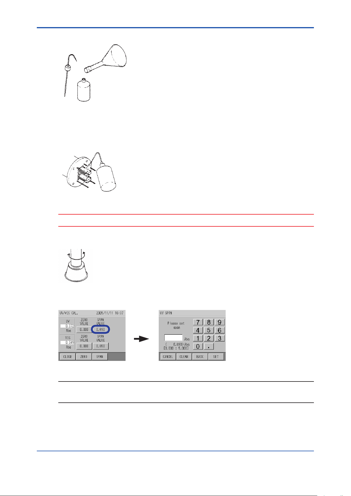
7. Press the button for [SPAN VALUE] for UV on the UV/VIS CAL. screen.
The screen changes to the UV SPAN screen.
NOTE
[CLEAR]: Clears all input numeric values.
[BACK]: Clears the rightmost number.
8. Enter the concentration value of compounded span calibration solution with the numeric
keypad, and press [SET].
Input range: 0.000 Abs to 5.000 Abs or 0.0 m-1 to 500.0 m
IM 12K01B02-01E
-1
Page 50
<5. Calibration>
The screen returns to the UV/VIS CAL. screen.
CAUTION
• The decimal place of the input range varies according to the setting in “6.5.2 Setting of
Decimal Place for each Component”.
• Refer to “5.4.1 How to Prepare Calibration Solution” for the concentration value of
compounded span calibration solution.
• If performing either one of the calibrations, set the span calibration value to “0” for the
component that is not being calibrated. By doing this, the span calibration for single
component becomes possible.
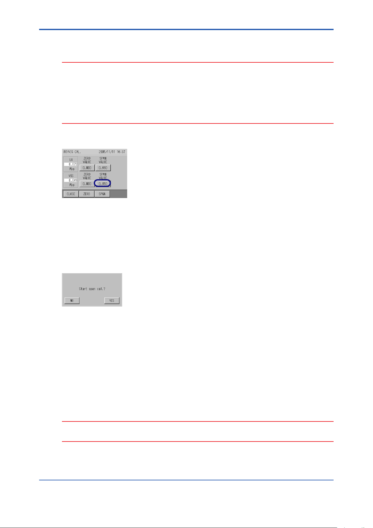
9. Press the button for [SPAN VALUE] for VIS on the UV/VIS CAL. screen.
5-11
10. Enter the concentration value of compounded span calibration solution with the numeric
keypads, and press [SET],
Input range: 0.000 Abs to 5.000 Abs or 0.0 m-1 to 500.0 m
The screen returns to the UV/VIS CAL. screen.
11. After waiting for 3 minutes and conrming that the measurement value is stabilized, press
[SPAN].
The “Start span cal.?” screen is displayed.
12. Press [YES] to start the span calibration.
The “Calibrating” screen is displayed.
After calibration, the “Calibration nished” screen is displayed.
13. Press [YES].
The span calibration value for UV/VIS is updated.
14. The common span calibration is nished.
If performing another span calibration subsequently, start the span calibration with the
detector still in the calibration tank.
-1
If nishing the calibration, set the detector in the measuring tank.
CAUTION
Do not reuse the calibration solution used in the calibration tank. The accuracy of calibrated value
may be lost.
IM 12K01B02-01E
Page 51
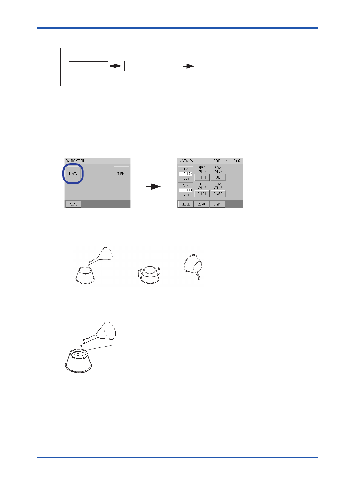
<5. Calibration>
Calibration item
[UV/VIS]
Pour approximately 100 mL
of span solution.
Clean the tank inside. Discard the solution.
Shake up and down
Scale
Amount to the scale is approximately 1.3 L.
5.4.4 Individual (UV) Span Calibration
[CAL.] [UV/VIS]
5-12
MEAS. screen
Refer to “5.3 Calibration Screen Display”
CALIBRATION screen
UV/VIS CAL. screen
Perform the individual (UV) span calibration after nishing the common span calibration.
• Preparation
Calibration tank: 1
Span calibratio solution: 2 L (measuring ask)
Cleaning bottle: 1
• Calibration procedure
1. Press [UV/VIS] from the CALIBRATION screen of converter.
2. Clean the attached calibration tank with zero solution throughly, pour approximately 100 mL
of the span calibration solution of acid potassium phthalate (from the 2 L measuring ask),
which is prepared by following “5.4.1 How to Prepare Calibration Solution”, and clean the
tank inside.
3. After cleaning, pour the individual span solution to the scale.
IM 12K01B02-01E
Page 52
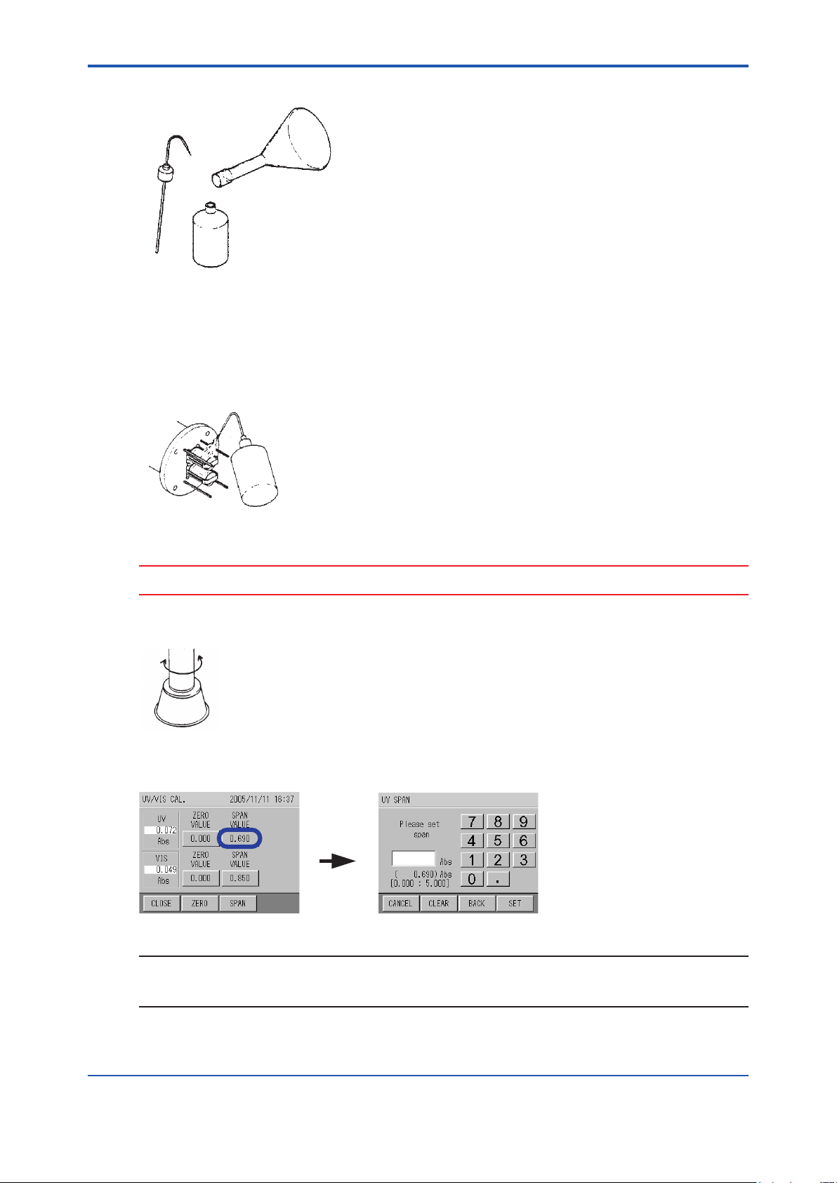
<5. Calibration>
Clean the cell unit using the cleaning bottle containing
the individual (UV) span solution.
Allow the solution to adhere by shaking from side to side
for several times.
[X.XX]
4. Pour the residual individual span solution into the cleaning bottle.
Residual individual (UV) span solution
Cleaning bottle
When performing span calibration, the calibration work can be performed smoothly if the
preparation through step 4 is performed together with the preparation for the common zero
calibration.
5. Take the detector from the zero calibration tank, and clean the cell unit using the cleaning
bottle containing the individual span solution.
5-13
CAUTION
Do not spill any solution on the base of the cell rotary shaft (V-ring seal part).
6. After cleaning the cell unit with the individual span solution, dip in the calibration tank.
7. Press the button for [SPAN VALUE] for UV on the UV/VIS CAL. screen.
The screen changes to the UV SPAN screen.
NOTE
[CLEAR]: Clears all input numeric values.
[BACK]: Clears the rightmost number.
IM 12K01B02-01E
Page 53
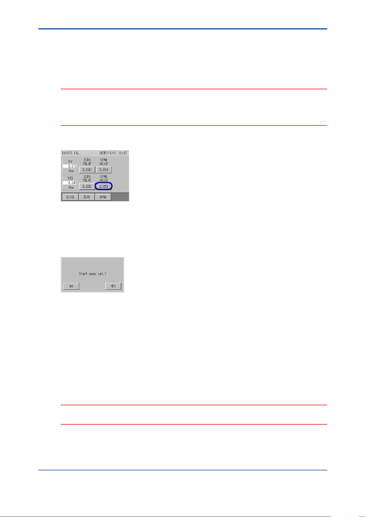
<5. Calibration>
8. Enter the concentration value of compounded span calibration solution with the numeric
keypad, and press [SET],
Input range: 0.000 Abs to 5.000 Abs or 0.0 m-1 to 500.0 m
The screen returns to the UV/VIS CAL. screen.
-1
CAUTION
• The decimal place input range varies according to the setting in “5.6.2 Setting of Decimal
place for each Component”.
• Refer to “5.4.1 How to Prepare Calibration Solution” for the concentration value of
compounded span calibration solution.
9. Press the button for [SPAN VALUE] for VIS on the UV/VIS CAL. screen.
5-14
10. Enter “0” with the numeric keypad, and press [SET],
The screen returns to the UV/VIS CAL. screen.
11. After waiting for 3 minutes and conrming that the measurement value has stabilized, press
[SPAN].
The “Start span cal.?” screen is displayed.
12. Press [YES] to start the span calibration.
The “Calibrating” screen is displayed.
After calibration, the “Calibration nished” screen is displayed.
13. Press [YES].
The span calibration value for UV/VIS is updated. VIS calibration value is not updated.
14. The individual span calibration is nished.
If performing TURB span calibration subsequently, start the TURB span calibration with the
detector still in the calibration tank.
If nishing the calibration, set the detector in the measuring tank.
CAUTION
Do not reuse the calibration solution used in the calibration tank. The accuracy of calibrated value
may be lost.
IM 12K01B02-01E
Page 54
<5. Calibration>
5.5 TURB (turbidity) Span Calibration
Only the span calibration is applied to the calibration method for TURB.
Perform TURB span calibration after performing the common zero calibration and the common
span calibration of UV/VIS.
Refer to “5.1 Calibration Pattern and its cycle”.
TURB span calibration is to obtain the turbidity coecient converted from the light absorption of
VIS.
The rough standard of the TURB measuring range is approximately 200 deg. by kaolin
concentration.
5.5.1 HowtoPreparetheCalibrationSolution
l <Reference>HowtoPreparetheTURBSpanCalibrationSolution
• Polystyrene latex (PSL) standard solution (100 deg.)
Adjust the calibration solution using the commercially available turbidity standard solution of
polystyrene latex (100 deg.).
NOTE
5-15
If using the calubration solution just after compounding it, air bubbles may aect the readings.
Stable calibration requires some time after compounding.
• Kaolin standard solution
Refer to JIS K 0101.
1. Puried kaolin
Sample QuantityJIS
Kaolin clay—
Sodium diphosphate decahydrateJIS K 8785
FormaldehydeJIS K 8872
Put approximately 10 g of kaolin clay into the 500 mL beaker, add the 300 mL of water and
0.2 g of sodium diphosphate decahydrate designated by JIS K 8785, and stir hard using the
magnetic stirrer for approximately 3 minutes. Pour the solution into the 1000 mL measuring
cylinder (lid is available), add the water to the 1000 mL gauge line, put on the lid, and stir
hard for approximately 1 minute. After leaving the solution at rest for 1 hour in ambient
temperature, discard 250 mL of the solution from the top using a siphon, and obtain another
250 mL of solution.
Centrifuge the solution in 3000 min-1 (adjusting the rotating speed according to the semi
diameter of the rotary part of the centrifugal separator) for 20 minutes, or lter using a lter
with a pore diameter of under 1 µm.
Heat the ltered kaolin at a temperature of 105 °C to 110 °C for approximately 3 hours,
stand to cool in the desiccators, and keep the solution in a wide-mouth bottle.
cool in the desiccators, and keep the solution in a wide-mouth bottle.
Approximately 10 g
0.2 g
Approximately 10 mL
2. Concentrated kaolin standards solution (1000 deg.)
Take 1.00 g of the puried kaolin to disperse in a moderate amount of water, and pour
the full dosage of kaolin standard solution into the 1000 mL ask. Then, after adding
approximately 800 mL of pure water and approximately 10 mL of formaldehyde designated
by JIS K 8872, add pure water up to the gauge line.
IM 12K01B02-01E
Page 55

<5. Calibration>
Calibration item
[TURB.]
Pour approximately 100 mL
of span solution.
Clean the tank inside. Discard the solution.
Shake up and down
3. Kaolin standard solution (for 100 deg.)
After shaking up the concentrated kaolin standard solution (1000 deg.) which is
commercially available or compounded by following the above mentioned table,
immediately take the 200 mL and pour into the 2000 mL measuring ask and add tap water
up to the gauge line.
CAUTION
• Make sure to use the pure water to dilute the TURB span calibration solution. Do not use tap
water, groundwater, or industrial water.
• Kaolin standard solution can be deposited easily. Agitate the standard solution sucientry
before calubration.
5.5.2 TURB (turbidity) Span Calibration
[CAL.] [UV/VIS]
5-16
MEAS. screen
Refer to "5.3 Calibration Screen Display"
CALIBRATION screen
TURB CAL. screen
Perform the TURB span calibration after nishing the common zero calibration and the
common span calibration.
• Preparation
Calibration tank: 1
Span calibration solution: 2 L (measuring ask)
Cleaning bottle: 1
• Calibration procedure
1. Press [TURB.] on the CALIBRATION screen of the converter.
2. Clean the attached calibration tank with zero solution thoroughly, pour approximately 100
mL of the TURB span solution (from the 2 L measuring ask), which is prepared by following
“5.5.1 How to Prepare the Calibration Solution”, and clean the tank inside.
IM 12K01B02-01E
Page 56
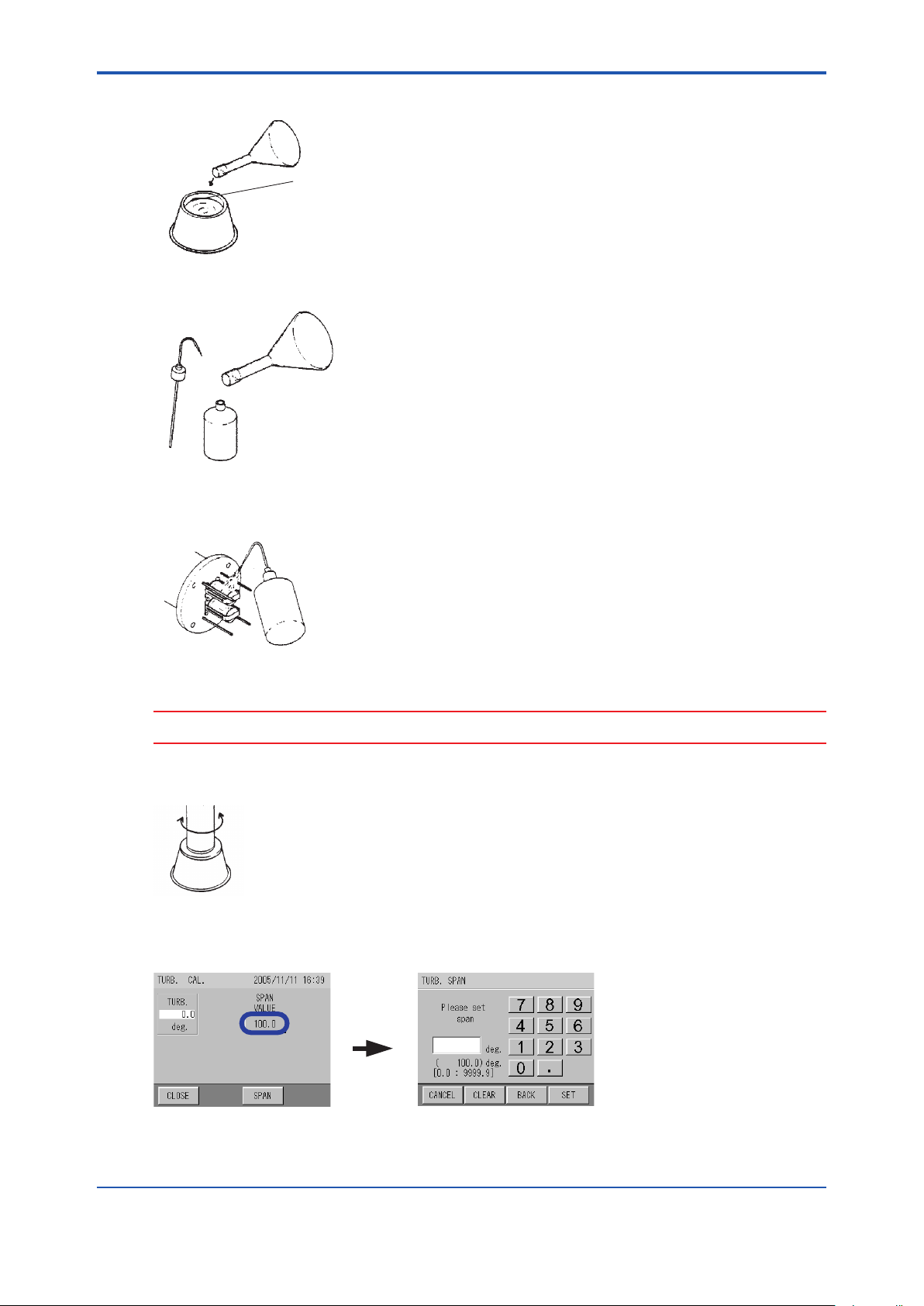
<5. Calibration>
Scale
Amount to the scale is approximately 1.3 L.
Cleaning bottle
Residual TURB span solution
Clean the cell unit using the TURB span solution
in the cleaning bottle.
Allow the solution to adhere by shaking from side to side
for several times.
[X.XX]
3. After cleaning, pour the TURB span solution to the scale.
4. Pour the residual TURB span solution into the cleaning bottle.
5. Take the detector from the calibration tank, and clean the cell unit using the TURB span
solution in the cleaning bottle.
5-17
CAUTION
Do not spill any solution on the base of cell rotary shaft (V-ring seal part).
6. After cleaning the cell unit with the TURB span solution, dip in the calubration tank.
7. Press the button for [SPAN VALUE] on the TURB. CAL. screen.
The screen changes to the TURB. SPAN screen.
IM 12K01B02-01E
Page 57
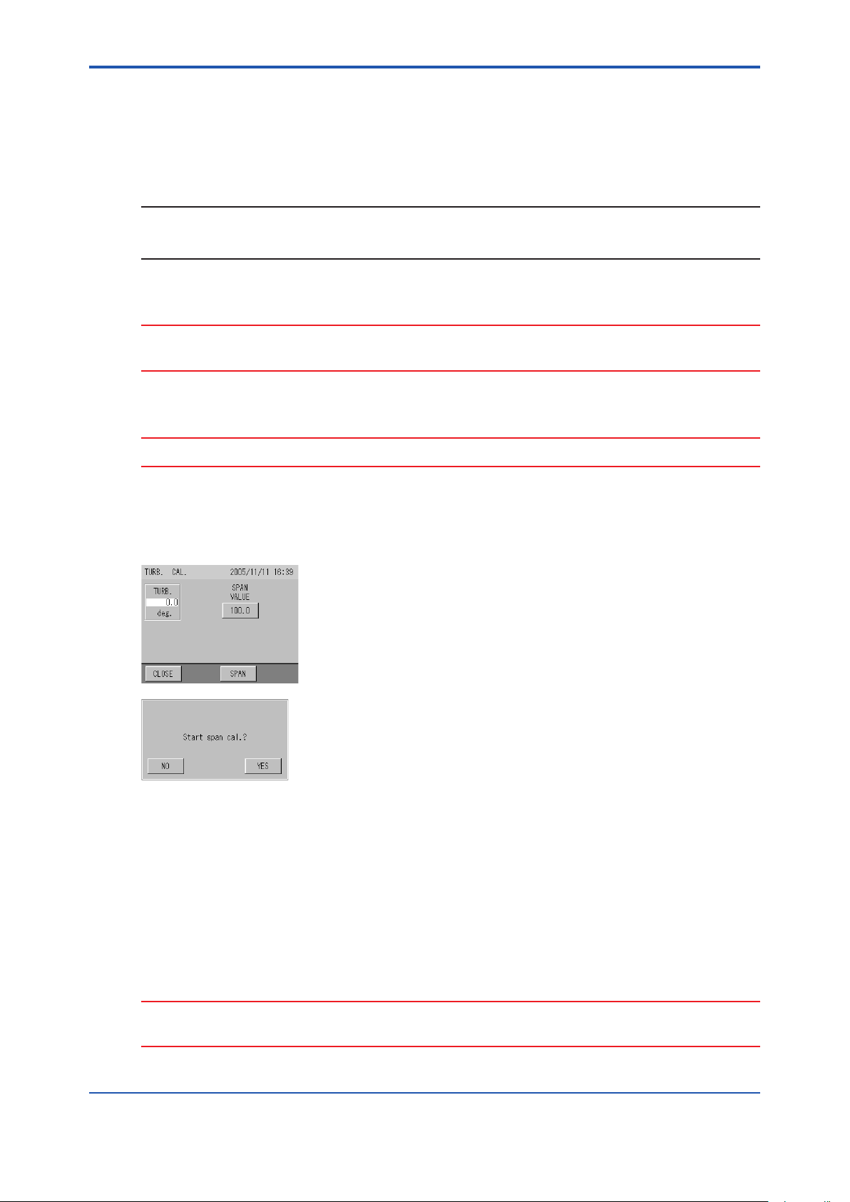
<5. Calibration>
8. Enter the concentration value of compounded TURB calibration solution with numeric
keypad, and press [SET],
Input range : 0.00 to 9999.99
The screen returns to the TURB. CAL. screen.
NOTE
[CLEAR]: Clears all input numeric value.
[BACK]: Clears the rightmost number.
CAUTION
The decimal place of input range varies according to the setting in “6.5.2 setting of Decimal place
for each Component”
CAUTION
Enter the concentration value of compounded calibration solution for TURB calibration value.
5-18
9. After waiting for 3 minutes and conrming that the measurement value is stabilized, press
[SPAN].
The “Start span cal.?” screen is displayed.
10. Press [YES] to start the span calibration.
“Calibrating” screen is displayed.
After calibration, “Calibration nished” screen is displayed.
11. Press [YES].
The span calibration value for TURB (turbidity) is updated.
12. The TURB span calibration is nished.
Set the detector in the measuring tank.
CAUTION
Do not reuse the calibration solution used in the calibration tank. The accuracy of calibrated value
may be lost.
IM 12K01B02-01E
Page 58

<6. Functions>
6. Functions
This unit has various functions. It is necessary to set various conditions to utilize these functions
fully. This chapter describes the functions and the setting procedures.
6.1 MEAS. (Measurement) Screen
The main screen displayed at the start when the power in ON.
Measurement screen contains two screens; the “CONC.” screen to display the COD
concentration and turbidity concentration, and the “Abs.” screen to display the light absorption of
UV, VIS, and UV-αVIS.
To switch screen, press the [Abs.] and [CONC.] buttons.
When the power is turned ON the CONC. screen is displayed. The previous measurement item
is memorized when the menu is switched.
[Abs.]
[CONC.]
6-1
6.2 TableofFunctions
Thoroughly understand the functions and set the functions so as to meet the customer’s needs.
Description ReferenceFunction
Sets signal reception and allocation from exterior,
and input and output setting during operation.
Sets the measurement range, unit, and upper and
lower limit for UV, VIS, COD, and TURB (turbidity).
Checks ON/OFF of motor for wipers and UV lamp. “6.6 Maintenance - Action”
Checks the unit information and input and output
operation.
Checks the measurement data saved in the memory.
Displays graphs of the measurement data saved in
the memory.
Displays the calibration report saved in the memory.
Saved the memorized data on the CF card or
initializes the CF card.
Immediately displays the alarm being triggered.
Displays the alarm history saved in the memory.
Maintenance
Data
Alarm
Setting
Measurement
setting
Action
Check
Log data
Graph
Calibration
report
CF card
Alarm
Alarm history
“6.4 Maintenance - Setting”
“6.5 Maintenance Measurement Setting”
“6.7 Maintenance - Check”
“6.8 Data Check”
“6.9 Alarm”
IM 12K01B02-01E
Page 59

<6. Functions>
6.3 Maintenance Screen Display
1. Press [MAINT.] on the MEAS. screen.
The MAINTENANCE screen appears.
2. Select the maintenance item with buttons displayed on the MAINTENANCE screen.
The MAINTENANCE screen for each item appears.
Displayed screenMAINTENANCE screen operation buttons
[SETTING]
SETTING screen
MEAS. SETTING screen[MEAS. SETTING]
ACTION screen[ACTION]
CHECK screen[CHECK]
6-2
MEAS.screen
[MAINT.]
[SETTING]
[ ]
[ ]
MAINTENANCE screen SETTING 1/2 screen SETTING 2/2 screen
[MEAS.SETTING]
MEAS.SETTING screen
[ACTION]
IM 12K01B02-01E
ACTION screen
[CHECK]
CHECK screen
Page 60

<6. Functions>
[SIGNAL
ALLOCATION]
[ ]
[ ]
6.4 Maintenance - Setting
All maintenance settings are performed here.
6.4.1 Signal Allocation
6-3
[MAINT.] [SETTING]
MEAS.
screen
Refer to "6.3 Maintenance Screen Display"
MAINTENANCE
screen
SETTING 1/2
screen
[SIGNAL INPUT SETTING]
SIGNAL ALLOCATION
screen (1/3)
The output terminals for analog output and contact output are allocated here.
1. Press [SIGNAL ALLOCATION] on SETTING 1/2 screen.
The SIGNAL ALLOCATION screen appears.
2. Output signal is allocated.
Setting item Description Initial setting
ANALOG OUTPUT A-1
ANALOG OUTPUT A-2 TURB
ANALOG OUTPUT A-3 UV
SIGNAL OUTPUT O-1
SIGNAL OUTPUT O-2 MAX COD
SIGNAL OUTPUT O-3 MAX TURB
SIGNAL OUTPUT O-4 NO SAMPLE
SIGNAL OUTPUT O-5
SIGNAL OUTPUT O-6
Sets to output either one of the following measurement component to
the analog output terminal from A-1 to A-3 Setting range:
UV, VIS, UV-VIS, COD, TURB, NONE
Sets to output either one of the following items to the output terminal of
contact output from O-1 to O-4 Setting range:
TOTAL ALARM, MAX COD, MAX TURB, MIN COD, MIN TURB, LAMP
ERR., NO SAMPLE, MOTOR ERR., ANALYZE ERR., WARM-UP
Outputs the following item to the output terminal O-5 of contact output.
POWER OFF (cannot be changed)
Outputs the following item to the output terminal O-6 of contact output.
MAINTENANCE (cannot be changed)
COD
TOTAL ALARM
POWER OFF
(xed)
MAINTENANCE
(xed)
Refer to “7 External Input and Output”
IM 12K01B02-01E
Page 61

<6. Functions>
MEAS.
screen
MAINTENANCE
screen
[MAINT.] [SETTING]
Refer to"6.3 Maintenance Screen Display"
SIGNAL INPUT SETTING
screen
SETTING 1/2
screen
[SIGNAL INPUT SETTING]
6.4.2 Signal Input Setting
Here enables clock time correction setting, such as setting external input of clock time and setting
correct clock time.
1. Press [SIGNAL INPUT SETTING] on the SETTING 1/2 screen.
The SIGNAL INPUT SETTING screen appears.
[SIGNAL INPUT
SETTING]
2. Press the button for EXT. IN SET.
6-4
EXT. IN SET screen appears.
3. Select the setting item and press [SET].
Setting item Description
OFF Receives botton operation only.
I/O Receives the input via contacts.
The screen returns back to the SIGNAL INPUT SETTING screen.
Setting for the system to receive the signal input is complete.
4. Press the button for ADJUST TIME.
ADJUST TIME screen appears.
5. Input the correct clock time when the external input is received.
The screen returns back to the SIGNAL INPUT SETTING screen.
Setting the clock time (when the external input is received) is complete.
IM 12K01B02-01E
Page 62

<6. Functions>
CAUTION
Only the time within 620 minutes of current set time can be input to set the correct clock time. If
the time out of this range is input, the setting becomes invalid.
6.4.3 Output Setting
6-5
[MAINT.] [SETTING]
MEAS.
screen
Refer to “6.3 Maintenance Screen Display”
MAINTENANCE
screen
SETTING 1/2
screen
[OUTPUT SETTING]
Here enables the output parameter setting.
Setting item Description Initial setting
ANALOG OUTPUT LEVEL
MAINT.OUTPUT
WARM-UP OUTPUT
ALARM OUTPUT
Sets the analog output level.
Setting range: 0 mA to 16 mA, 4 mA to 20 mA
Sets the measurement output during calibration/maintenance
to output by ont of the settings below.
Setting range: HOLD, DIRECT, PRESET (0 mA to 21 mA)
Sets the measurement output during warm-up to output by
one of the settings below.
Setting range: HOLD, DIRECT, PRESET (0 mA to 21 mA)
Sets the measruement output during an alarm to output by
one of the settings below.
Setting range: HOLD, DIRECT, PRESET (0 mA to 21 mA)
1. Press [OUTPUT SETTING] on the SETTING 1/2 screen.
The OUTPUT SETTING screen appears.
2. Press the button for ANALOG OUTPUT LEVEL.
OUTPUT SETTING
screen
4 mA to 20 mA
HOLD
PRESET
4.0 mA
HOLD
The ANALOG OUTPUT LEVEL screen appears.
3. Select the setting item from [0 - 16] or [4 - 20] and press [SET].
The screen returns back to the OUTPUT SETTING screen.
Setting for the analog output level is complete.
l Output setting during operation
Here describes the following three output setting methods.
• MAINT. OUTPUT
• WARM-UP OUTPUT
• ALARM OUTPUT
[MAINT.] [SETTING]
MEAS.
screen
Refer to “6.3 Maintenance Screen Display”
MAINTENANCE
screen
SETTING 1/2
screen
[OUTPUT SETTING]
OUTPUT SETTING
screen
IM 12K01B02-01E
Page 63

<6. Functions>
[HOLD]
/[DIRECT]
/[PRESET xxmA]
Setting item Description Initial setting
HOLD
Outputs the adjacent readings while holding.
If there are no adjacent readings when the power is
ON, the latest readings before the power OFF are held.
—
DIRECT Outputs the measured readings directly. —
PRESET
Outputs the preset values.
In this case, the log data is the reading equivalent to
the setting output value.
During maintenance and alarm: 21.0 mA
During warm-up: 4.0 mA
[PRESET]
1. Press the output item button to be set on the OUTPUT SETTING screen.
• MAINT. OUTPUT
• WARM-UP OUTPUT
• ALARM OUTPUT
The screens for the output of each item appear as follows;
The screen shows an example for MAINT. OUTPUT.
2. Select the setting item, and press [SET]
6-6
The screen returns back to the OUTPUT SETTING screen.
Output settings during operation are complete.
l WhensettingtoPRESET:
1. Press the [PRESET] button on the lower right of screen.
The PRESET screen for each item appears.
2. Enter the preset value with the numeric keypad, and press [SET],
Input range: 0.0 mA to 21.0 mA
CAUTION
When it is preset, the log data also becomes the preset value. The value corresponds to the
following calculating formula.
When the analog output level is 4 mA to 20 mA:
Full scale of measurement value 3 (preset value - 4) / 16
When the analog output level is 0 mA to 16 mA:
Full scale of measurement value 3 preset value / 16
IM 12K01B02-01E
Page 64

<6. Functions>
[OUTPUT CONDITION
SETTING]
NOTE
If the setting is changed while holding the readings, the setting change is enabled after the hold is
released.
6.4.4 Output Condition Setting
6-7
[MAINT.] [SETTING]
MEAS.
screen
Refer to “6.4.2 Signal Input Setting”
MAINTENANCE
screen
SETTING 1/2
screen
[OUTPUT CONDITION SETTING]
OUTPUT CONDITION
SETTING screen
Here enables the output conditions setting (such as the alarm discrimination time and the minus
display).
For normal usage, default setting can be used (no additional setting is required).
1. Press [OUTPUT CONDITION SETTING] on the SETTING 1/2 screen.
The OUTPUT CONDITION SETTING screen appears.
2. Press the button for ALARM DISCRIMI. TIME to change the discrimination time of the
alarm output, and enter the value of setting range. Press the button for MINUS DISPLAY to
activate/deactivate the minus display.
Setting item Description Initial setting
Sets the alarm delay time to ignore the spike alarm.
ALARM
DISCRIMI. TIME
MINUS
DISPLAY
When the time exceeds the ALARM DISCRIMI. TIME, the alarm is
triggered and sounds continuously.
(Set to "0" minute if you want to occur the alarm immediately.)
Setting range: 0 to 99 minuites
Sets whether to display the measurement value.
Setting range: OFF or ON
The screen returns back to the OUTPUT CONDITION SETTING screen.
The output condition setting is complete.
6.4.5 Time Adjustment
[MAINT.] [SETTING]
MEAS.
screen
Refer to “6.3 Maintenance Screen Display”
The clock can be set here.
1. Press the [TIME ADJUSTMENT] button on the SETTING 2/2 screen.
The TIME ADJUSTMENT screen appears.
MAINTENANCE
screen
SETTING 1/2 screen
[ ]
SETTING 2/2 screen
5 min
OFF
IM 12K01B02-01E
Page 65
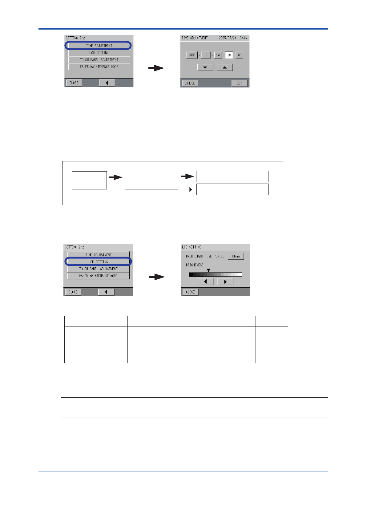
<6. Functions>
[TIME
ADJUSTMENT]
[LCD SETTING]
2. Select the items from year/month/date/hour/minute to be changed and enter numbers using
the [▲] and [▼] buttons.
After entering the time, press [SET].
The screen returns back to the SETTING 2/2 screen.
Time adjustment is complete.
6.4.6 LCD Setting
[MAINT.] [SETTING]
6-8
MEAS.
screen
MAINTENANCE
screen
SETTING 1/2 screen
[ ]
SETTING 2/2 screen
Refer to “6.3 Maintenance Screen Display”
The condition setting of the LCD can be set here.
1. Press [LCD SETTING] on the SETTING 2/2 screen.
The LCD SETTING screen appears.
The LCD setting contains the following items:
Setting item Description Initial setting
BACKLIGHTTIME
PERIOD Setting
BRIGHTNESS Adjustment Adjusts the brightness of the backlight. —
Sets the auto-off timer of the LCD backlight (after the last
touch).
Setting range: (10 min, 20 min, 30 min)
OFF (backlight is always ON)
10 min
2. Change the condition to be set, and the setting is complete.
NOTE
If no button is pressed for about 30 minutes on display in the LCD SETTING screen, the display
returns back to the previous setting screen.
IM 12K01B02-01E
Page 66

<6. Functions>
MEAS.
screen
MAINTENANCE
screen
[MAINT.] [SETTING]
Refer to “6.3 Maintenance Screen Display”
SETTING 1/2 screen
SETTING 2/2 screen
[ ]
6.4.7 TouchPanelAdjustment
The touch panel can be adjusted here.
It is not necessary to adjust the touch panel for normal usage. When the touch panel functions
abnormally, such as when pressing a button activates a dierent button or when the location is
misaligned, adjust the touch panel.
1. Press [TOUCH PANEL ADJUSTMENT] on the SETTING 2/2 screen.
The TOUCH PANEL ADJUSTMENT screen appears.
[TOUCHPANEL
ADJUSTMENT]
6-9
2. Press the area indicated by the arrow.
After completing the adjustment, the screen returns back to the SETTING 2/2 screen.
6.4.8 MakerMaintenanceMode
As this mode is for the YOKOGAWA service personnel, it is not necessary to touch this setting.
CAUTION
As the Maker Maintenance Mode is the mode to set the inside adjustment value, never enter this
mode. Doing so may cause a malfunction.
IM 12K01B02-01E
Page 67
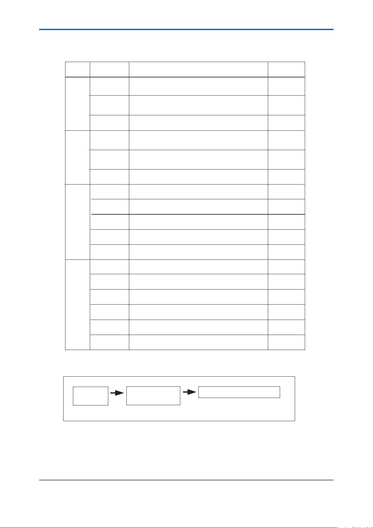
<6. Functions>
MEAS.
screen
MAINTENANCE
screen
[MAINT.] [MEAS.SETTING]
Refer to “6.3 Maintenance Screen Display”
MEAS.SETTING screen
6.5 Maintenance - Measurement Setting
Measurement settings contains the following items:
6-10
Setting
item
UV
VIS
COD
TURB
(turbidity)
Setting item Initial settingDescription
MEAS. RANGE
DECIMAL
PLACE
UNIT
MEAS. RANGE
DECIMAL
PLACE
TUREB. COR.
FAC.
MEAS. RANGE
DECIMAL
PLACE
Y = a + bX
MAX ALARM
VALUE
MIN ALARM
VALUE
MEAS. RANGE
DECIMAL
PLACE
Y = a + bX
MAX ALARM
VALUE
MIN ALARM
VALUE
UNIT
Sets the measurement range.
Setting range: (when the unit is "Abs") 0.1 to 5.0
(when the unit is "m
Sets the decimal place of the measurement value.
Setting rage: (when the unit is "Abs") 3 and 4
(when the unit is "m
Sets the measurement unit of UV, VIS, and UV-aVIS.
Setting range: Abs and m
Sets the measurement range.
Setting range: (when the unit is "Abs") 0.1 to 5.0
(when the unit is "m
Sets the decimal place of the measurement value.
Setting rage: (when the unit is "Abs") 3 and 4
(when the unit is "m
Sets the turbidity correction factor.
Setting range: 0.000 to 9.999
Sets the measurement range.
Setting range: 0.1 to 9999.9
Sets the decimal place of the measurement value.
Setting rage: 0 to 3
Set the COD conversion factor a and b by calculating
from UV-aVIS
Set the upper limit of COD alarm value.
Sets the lower limit of COD alarm value.
Sets the measurement range.
Setting rage: 0.1 to 9999.9
Sets the decimal place of the measurement value.
Correction is possible when the readings differ from the
actual value due to the various causes even after calibration.
Sets the upper limit of TURB (turbidity) alarm value.
Sets the lower limit of TURB (turbidity) alarm value.
Sets the measurement unit of TURB (turbidity)
Setting range: deg., mg/L, and NTU
-1
") 10 to 500
-1
") 1 and 2
-1
-1
") 10 to 500
-1
") 1 and 2
1.0 Abs
3
Abs
1.0 Abs
3
0.000
1.0 mg/L
1
a = 0
b = 1.000
1
0
1.0 deg.
1
a = 0
b = 1.000
1
0
deg.
l SettingScreenDisplayforeachMeasuringComponent
1. Press a measuring component button on the MEAS. SETTING screen. (Press [UV] or
[COD] for the following example.)
The setting screen for each measuring component appears.
The screens show examples for UV and COD.
IM 12K01B02-01E
Page 68
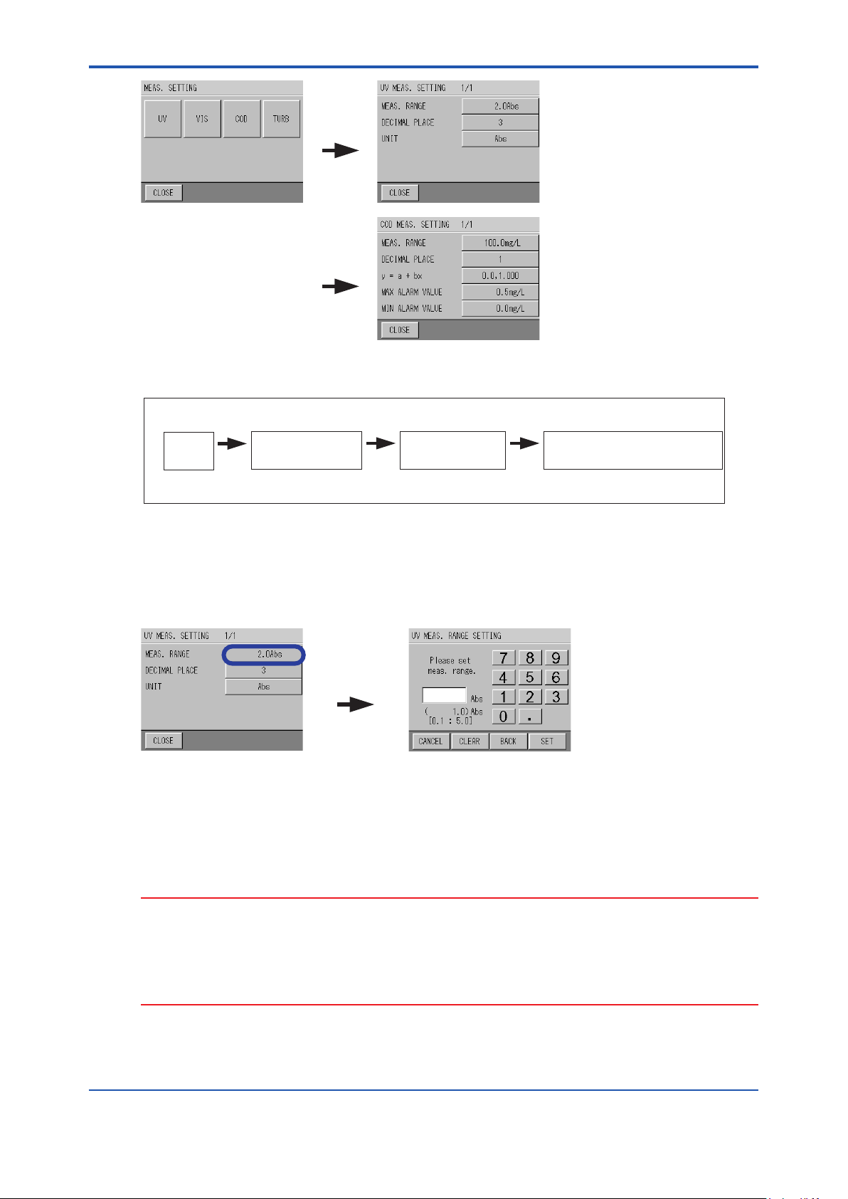
<6. Functions>
[UV]
[COD]
MEAS. RANGE
6.5.1 MeasuringRangeSettingforeachComponent
6-11
[MAINT.]
MEAS.
screen
Refer to “6.5 Setting Screen Display for each Measuring Component”
MAINTENANCE
screen
[MEAS.SETTING]
MEAS. SETTING
screen
[UV][VIS][COD][TURB]
MEAS. SETTING for each
measuring component screen
The measuring range for each measuring component is set here.
1. Press the button for MEAS. RANGE on the MEAS. SETTING for each measuring
component screen.
The MEAS. RANGE SETTING for each measuring component screen appears.
The screen shows an example for UV.
2. Enter the numeric setting range and press [SET].
The screen returns back to the MEAS. SETTING for each measuring component screen.
The measuring range setting for each measuring component is complete.
Perform the same procedure to set the measuring range for the other components.
CAUTION
• Set the measuring range so as not to exceed the full scale of the measurement value (level
of approximately 80%).
• If the measuring range is changed while measuring, the measurement value may go wrong.
In this case, perform the calibration using a matching calibration solution.
• The measuring range for UV-αVIS is the same as that for UV.
IM 12K01B02-01E
Page 69
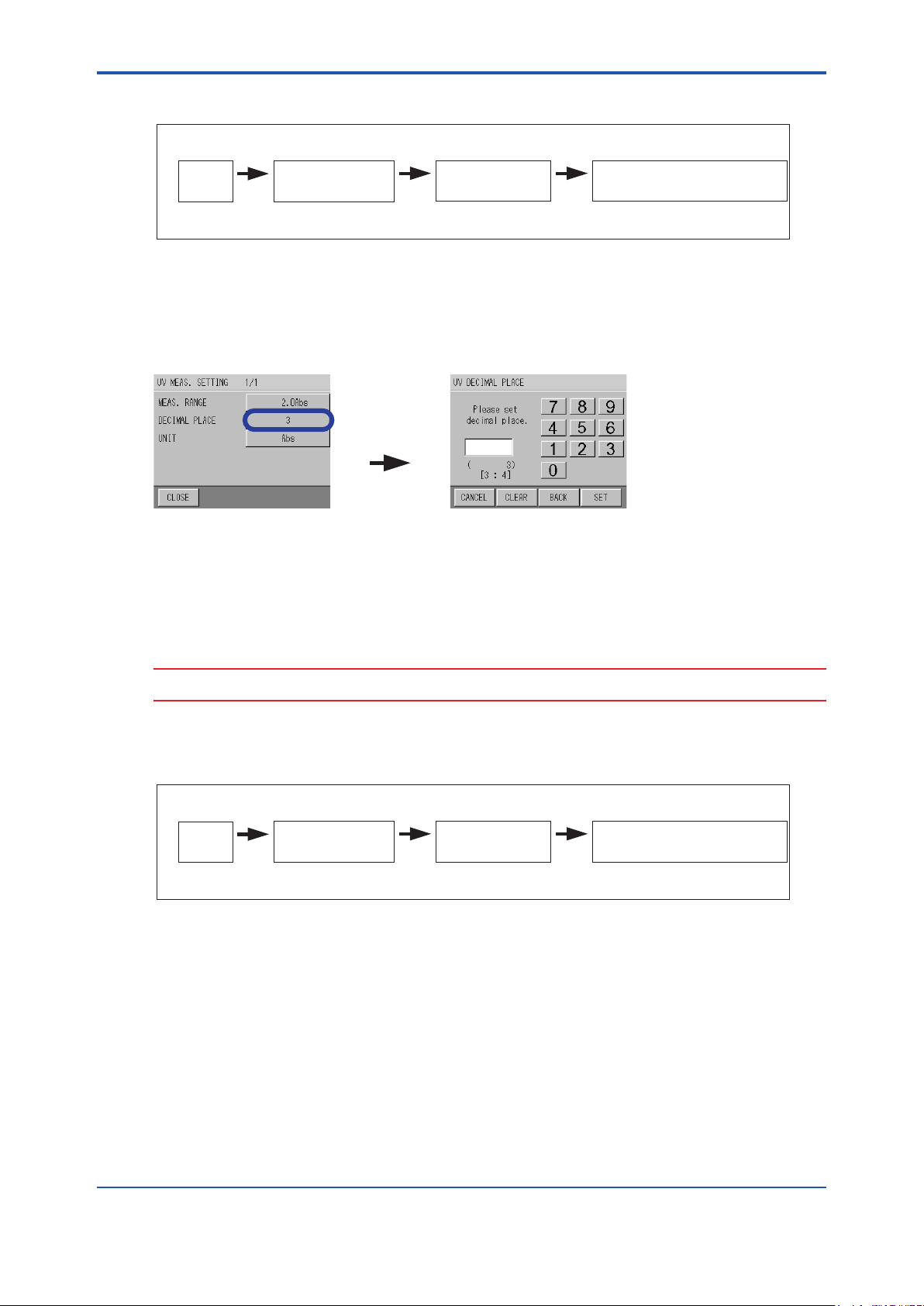
<6. Functions>
DECIMAL
PLACE
6.5.2 SettingofDecimalPlaceforeachComponent
6-12
[MAINT.]
MEAS.
screen
Refer to “6.5 Setting Screen Display for each Measuring Component”
MAINTENANCE
screen
[MEAS.SETTING]
MEAS. SETTING
screen
[UV][VIS][COD][TURB]
MEAS. SETTING for each
measuring component screen
The decimal place for each measuring component is set here.
1. Press the button for DECIMAL PLACE on the MEAS. SETTING for each measuring
component screen.
The DECIMAL PLACE screen appears.
The screen shows an example for UV.
2. Enter a numeric value for the decimal place and press [SET].
The screen returns back to the MEAS. SETTING for each measuring component screen.
The decimal place setting for each measuring component is complete.
Perform the same procedure to set the measuring range for the other components.
CAUTION
The decimal place for UV-αVIS is the same as that for UV.
6.5.3 UnitSettingforUV,VIS,andUV-αVIS
[MAINT.]
MEAS.
screen
Refer to “6.5 Setting Screen Display for each Measuring Component”
MAINTENANCE
screen
[MEAS.SETTING]
MEAS. SETTING
screen
The units for UV, VIS, and UV-αVIS are set here. Select “Abs” when indicating UV, VIS, and
UV-αVIS in a cell length conversion of 10 mm, and select “m-1” when indicating UV, VIS, and
UV-αVIS in a cell length conversion of 1 m (the indication of “m-1” is the hundredfold of the
indication of “Abs” ).
When the unit is changed, the range that can be measured simultaneously is also changed.
[UV]
UV MEAS. SETTING
screen
IM 12K01B02-01E
Page 70
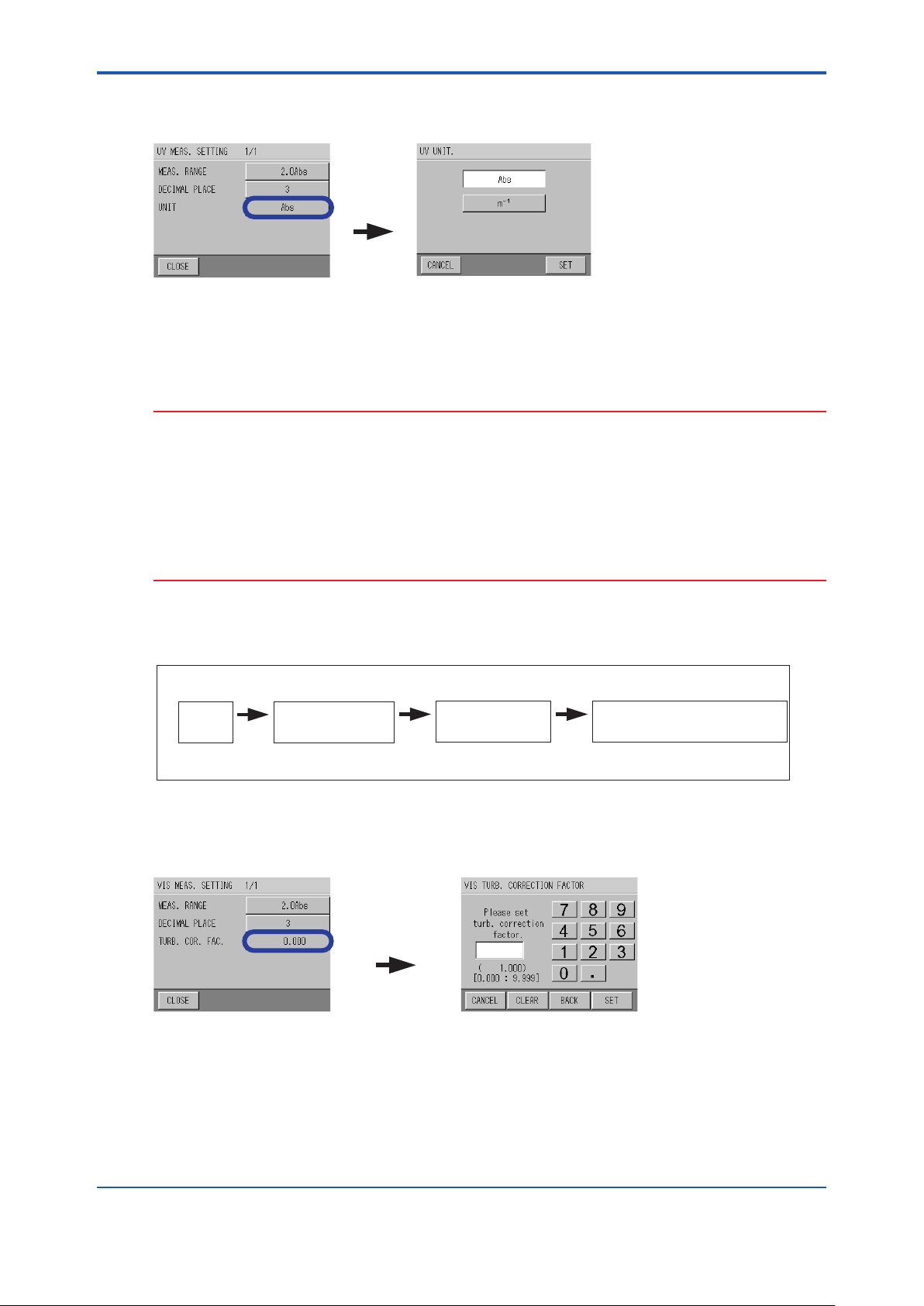
<6. Functions>
UNIT
TURB.COR.FAC.
(α)
1. Press the button for UNIT on the UV MEAS. SETTING screen.
The UV UNIT screen appears.
2. Select the unit and press [SET].
The screen returns back to the UV MEAS. SETTING screen.
Unit setting for UV, VIS, and UV-αVIS is complete.
CAUTION
• In accordance with the change of unit settings for UV, unit setting for VIS and UV-αVIS is
also changed.
• In accordance with the unit change, the decimal place and measuring range indication are
also changed. However, the value b of “y = a + bx” for COD and TURB (turbidity) and span
calibration value for TURB (turbidity) are not changed. Perform settings and calibration
again.
• If the unit is changed while measuring, digits of saved data may be lost. Make sure to
change the unit at the beginning of operation.
6-13
6.5.4 SettingofTurbidityCorrectionFactor
[MAINT.]
MEAS.
screen
Refer to “6.5 Setting Screen Display for each Measuring Component”
MAINTENANCE
screen
[MEAS.SETTING]
MEAS. SETTING
screen
The turbidity correction factor “a” used for the calculation of UV-αVIS is set here.
1. Press the button for TURB. COR. FAC. on the VIS MEAS. SETTING screen.
The VIS TURB. CORRECTION FACTOR screen appears.
2. Enter the numeric turbidity correction factor “α” and press [SET].
The screen returns back to the VIS MEAS. SETTING screen.
Unit setting for turbidity correction factor is complete.
[VIS]
VIS MEAS. SETTING
screen
IM 12K01B02-01E
Page 71
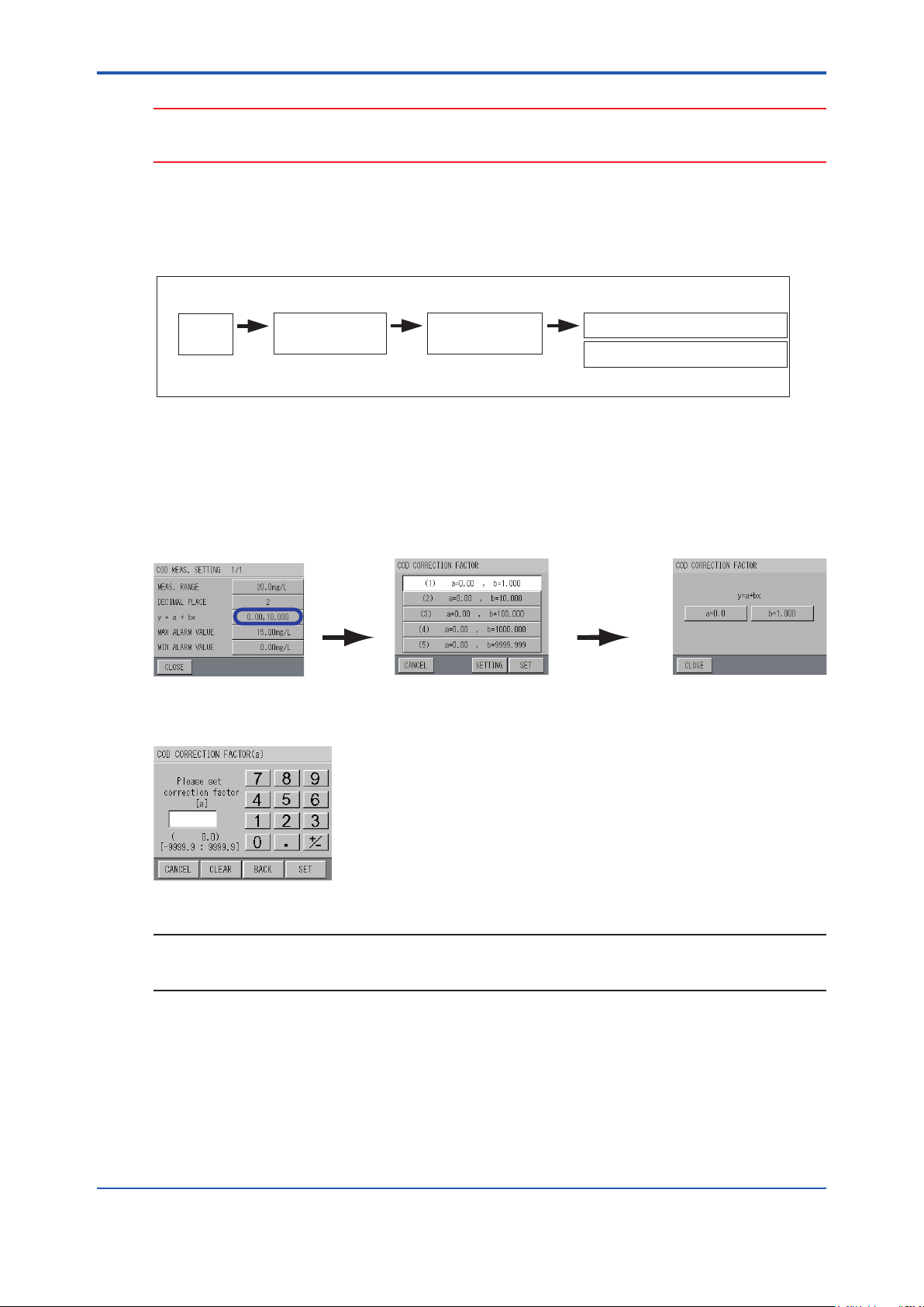
<6. Functions>
CAUTION
Enter the turbidity correction factor “a” when the sample water contains much turbidity to cause a
poor correlation between the UV value and COD value by manual analysis.
6.5.5 SettingofCODConversionFactorandTurbidity
CorrectionFactor
6-14
[MAINT.]
MEAS.
screen
Refer to “6.5 Setting Screen Display for each Measuring Component”
MAINTENANCE
screen
[MEAS.SETTING]
MEAS. SETTING
screen
[COD][TURB]
COD MEAS. SETTING screen
TURB MEAS. SETTING screen
Here describes how to set the COD conversion factor from UV-αVIS and Turbidity correction
factor.
Refer to “How to Calculate the COD Conversion Factor”
1. Press the button for y = a + bx on the COD or TURB MEAS. SETTING screen.
The CORRECTION FACTOR screen appears.
The screen shows an example for COD.
Correction factor of
a, b for each (1) to (5)
[a=x.xx b=x.xxx]
on the avobe screen
cab be set.
2. Press [a=x.x].
The CORRECTION FACTOR (a) for COD or TURB screen appears.
NOTE
[CLEAR]: Clears all input numeric values.
[BACK]: Clears the rightmost number.
IM 12K01B02-01E
Page 72
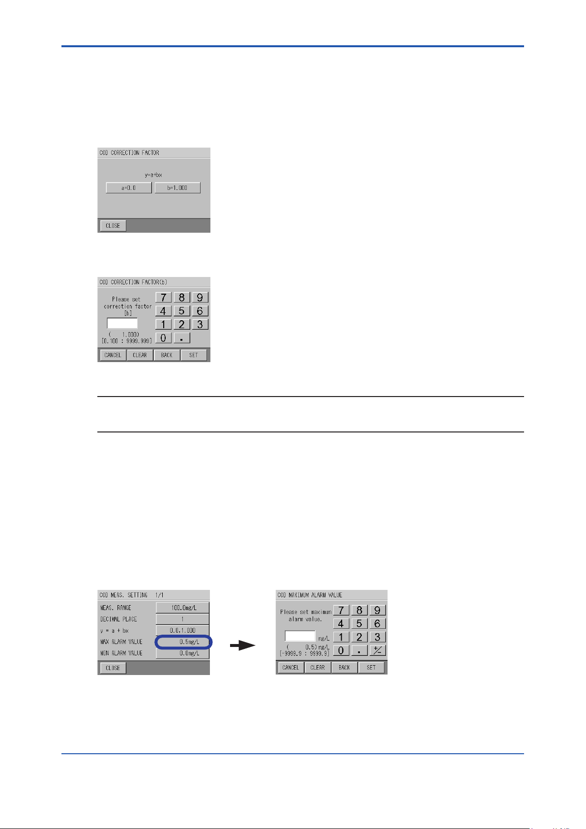
<6. Functions>
MAX ALARM
VALUE
3. Enter the value of “a” with the numeric keypad, and press [SET].
Input range: -9999.9 to 9999.9
(When the decimal place is set to 1 digit, the decimal place increases according to the
setting digits.)
The screen returns back to CORRECTION FACTOR screen for each measuring
component.
4. Press [b=x.xxx].
The CORRECTION FACTOR (b) screen for each measuring component appears.
6-15
NOTE
[CLEAR]: Clears all input numeric values.
[BACK]: Clears the rightmost number.
5. Enter the value “b” with the numeric keypad, and press [SET].
Input range: 0.1 to 9999.9
(When the decimal place is set to 1 digit, the decimal place increases according to the
setting digits.)
The screen returns back to the y = a + bx screen for each measuring component.
The setting of the conversion factor and measurement correction factor are complete.
6.5.6 Setting of MAX Alarm Value for COD and TURB (turbidity)
1. Here describes how to set the upper limits of the COD and TURB alarm values.
Press the button of the measuring component on the COD or TURB MEAS. SETTING
screen.
The MEAS. SETTING screen for each measuring component appears.
IM 12K01B02-01E
Page 73
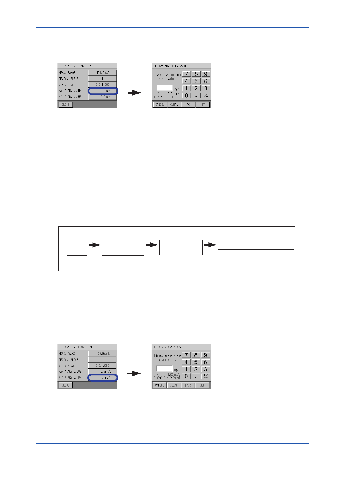
<6. Functions>
MAX ALARM
VALUE
2. Press the button for MAX ALARM VALUE.
The MAXIMUM ALARM VALUE screen for each measuring component appears.
The screen shows an example of MAX ALARM VALUE for COD.
3. Enter the upper limit value with the numeric keypad, and press [SET].
Input range: -9999.9 to 9999.9
(When the decimal place is set to 1 digit, the decimal place increases according to the
setting digits.)
NOTE
[CLEAR]: Clears all input numeric values.
[BACK]: Clears the rightmost number.
6-16
6.5.7
The screen returns back to the MEAS. SETTING screen for each measuring component.
Setting of MIN Alarm Value for COD and TURB (turbidity)
[MAINT.]
MEAS.
screen
Refer to “6.5 Setting Screen Display for each Measuring Component”
MAINTENANCE
screen
[MEAS.SETTING]
MEAS. SETTING
screen
Here describes how to set the lower limits of the COD and TURB alarm values.
1. Press the button of the measuring component on the COD or TURB MEAS. SETTING
screen.
The MEAS. SETTING screen for each measuring component appears.
2. Press the button for MIN ALARM VALUE.
The MINIMUM ALARM VALUE screen for each measuring component appears.
The screen shows an example of MINIMUM ALARM VALUE for COD.
MIN ALARM
VALUE
[COD][TURB]
COD MEAS. SETTING screen
TURB MEAS. SETTING screen
3. Enter the lower limit value with the numeric keypad, and press [SET].
Input range: -9999.9 to 9999.9
(When the decimal place is set to 1 digit, the decimal place increases according to the
The screen returns back to the MEAS. SETTING screen for each measuring component.
IM 12K01B02-01E
setting digits.)
Page 74

<6. Functions>
UNIT
6.5.8 Unit Setting for TURB (turbidity)
6-17
[MAINT.]
MEAS.
screen
Refer to “6.5 Setting Screen Display for each Measuring Component”
MAINTENANCE
screen
[MEAS.SETTING]
MEAS. SETTING
screen
[TURB]
TURB MEAS. SETTING 1/2 screen
[ ]
TURB MEAS. SETTING 2/2 screen
Here describes how to set the unit for TURB.
Select one of the turbidity units from “deg.”, “mg/L”, or “NTU”.
1. Press the button for UNIT on the TURB MEAS. SETTING 2/2 screen.
The TURB UNIT screen appears.
2. Select the unit and press [SET].
The screen returns back to the TURB MEAS. SETTING 2/2 screen.
Unit setting for turbidity is complete.
NOTE
It is common to set “deg.” when the calibration solution is PSL, “mg/L” when the calibration
solution is kaolin, and “NTU” when the calibration solution is forumajin.
6.6 Maintenance - Action
This function performs operations using the operating buttons.
Action
WIPER MOTOR Check the ON / OFF operation of the rotary ell wiper motor.
UV LAMP Check the ON / OFF operation of the UV lamp for light.
6.6.1 Action
[MAINT.] [ACTION]
MEAS.
screen
Refer to “6.3 Maintenance Screen Display”
MAINTENANCE
screen
Description
ACTION screen
Here describes the execution methods for wiper motor and UV lamp.
IM 12K01B02-01E
Page 75

<6. Functions>
[ACTION]
1. Press the [ACTION] button on the MAINTENANCE screen.
The ACTION screen appears.
2. Every time the item to be activated is pressed, the value switches between ON and OFF.
The action is activated. Check whether the value has been activated normally.
3. Press [CLOSE] to return back to the MAINTENANCE screen.
Press [CLOSE] to return back to the ON condition automatically.
CAUTION
• When checking the action, never touch the cell part, and never directly look at the UV lamp;
it is dangerous.
• When performing the action, the motor and lamp are stopped and abnormal measurement
values may be recorded.
• If the MAINTENANCE – ACTION screen is not touched (backlight is not turned on) for about
2 hours, the screen will return to the MEASUREMENT screen. When the screen is touched
once and the backlight is turned on, the timer will be reset and the screen will not return to
the MEASUREMENT screen until about 2 hours have elapsed.
• Note that the screen will return to the MAINTENANCE screen and automatically the wiper
motor and UV lamp will be turned on if no buttons are pressed for 30 minutes on the
MAINTENANCE – ACTION screen. When any button is pressed within 30 minutes, the
timer will be reset and actions will be performed as specied on the screen until 30 minutes
have elapsed.
6-18
6.7 Maintenance-Check
Items to be checked are as follows:
IM 12K01B02-01E
Items
Unit information and ID
setting check
External input and output
check
Analog input value check
Analog output
transmission check
Checks the unit model and ID etc, and sets the ID.
The ID number is used as the folder name of the data which is transferred to the
CF card.
Checks the operation of the contact input and output.
Checks the analog signal value for measurement transferred from the detector.
Can be used to simply check whether it is activated or not (for service personnel).
Checks the analog output value.
Description
Page 76

<6. Functions>
[CHECK UNIT
INFORMATION]
[SET ID]
6.7.1 Unit Information
[MAINT.] [CHECK]
6-19
MEAS.
screen
Refer to “6.3 Maintenance Screen Display”
1. Press the [CHECK UNIT INFORMATION] on the CHECK screen.
The CHECK UNIT INFORMATION screen appears.
Information about the model number and individual ID are displayed.
MAINTENANCE
screen
6.7.2 Individual ID Setting
1. Press the [SET ID] on the CHECK UNIT INFORMATION screen.
The INDIVIDUAL ID SETTING screen appears.
CHECK screen
2. Enter the ID number with the numeric keypad, and press [SET].
Input range: 00000000 to 99999999
NOTE
[CLEAR]: Clears all input numeric values.
[BACK]: Clears the rightmost number.
The screen returns back to CHECK UNIT INFORMATION screen.
6.7.3 ExternalInput/OutputCheck
[MAINT.] [CHECK]
MEAS.
screen
Refer to “6.3 Maintenance Screen Display”
Check the input and output of the external unit.
MAINTENANCE
screen
CHECK screen
IM 12K01B02-01E
Page 77

<6. Functions>
[CHECK
EXTERNAL I/O]
[CHECK ANALOG
INPUT]
1. Press the [CHECK EXTERNAL I/O] on the CHECK screen.
The CHECK EXTERNAL I/O 1/2 screen appears.
The following can be checked.
I1: Float switch input from sample
I2: External input check of clock set
I3: Switch input check during maintenance
2. Contact output can be checked on the CHECK EXTERNAL I/O 2/2 screen
O-1 to O-4: Allocated contact
O-5: Power OFF (only O-5 is for action, contact is OFF when power is ON, and contact is
ON when power is OFF)
O-6: During maintenance (check when the switch is OFF during maintenance)
6-20
CAUTION
Remove the wirings of the unit before checking the contact action (as it may aect the external
measuring instruments).
6.7.4 CheckAnalogInput
[MAINT.] [CHECK]
MEAS.
screen
Refer to “6.3 Maintenance Screen Display”
The sensor analog input transmitted from the detector is displayed.
1. Press the [CHECK ANALOG INPUT] button on the CHECK screen.
The CHECK ANALOG INPUT screen appears.
The analog input from each sensor is displayed.
MAINTENANCE
screen
CHECK screen
CAUTION
This screen is the check screen for the service personnel.
IM 12K01B02-01E
Page 78

<6. Functions>
[CHECK ANALOG
OUTPUT]
6.7.5 CheckAnalogOutput
[MAINT.] [CHECK]
6-21
MEAS.
screen
MAINTENANCE
screen
CHECK screen
Refer to “6.3 Maintenance Screen Display”
NOTE
If no button is pressed for about 30 minutes on the CHECK ANALOG OUTPUT screen, the
display returns back to the previous setting screen.
1. Press the [CHECK ANALOG OUTPUT] on the CHECK screen.
The CHECK ANALOG OUTPUT screen appears.
2. Select the items to output by pressing the button ([x.xxmA]), change the number by using
the [.] and [m] buttons, and press [OUTPUT].
Output value: 0.00 / 4.00 / 8.00 / 12.00 / 16.00 / 20.00 mA
3. Check the output with an ammeter.
Refer to “7.2 Analog Output”
6.8 DataCheck
Items for the data check are as follows:
Items for data check
LOG DATA check
LOG DATA deletion
GRAPH display Checks the previous readings of data using a graph.
CAL. REPORT check Checks up to 20 history records by measurement component and zero/span.
CAL. REPORT deletion
ALARM REPORT check
ALARM REPORT deletion Deletes all of the alarm history.
CF CARD transfer Transfers the data to the CF card.
CF CARD initialization Initializes the CF card.
l Data Screen Display
Checks the previous data readings numerically. Approximately 11 days can be
saved for the value of 1 minute and approximately 13 months can be saved for
the value of 1 hour.
Deletes all of the log data.
Deletes all of the calibration report.
Checks up to 511 alarm history records.
Description
1. Press the [DATA] on the MEAS. screen.
The DATA screen appears.
IM 12K01B02-01E
Page 79

<6. Functions>
[LOG DATA]
1
During maintenance
2
During warm-up
3
During alarm
[DATA]
MEAS. screen
6.8.1 LogDataCheck
[DATA]
6-22
MEAS.
screen
Refer to “6.8 Data Screen Display”
DATA
screen
Displays the measurement value of 1 minute and 1 hour memorized by the measurement.
1. Press the [LOG DATA] on the DATA screen.
The LOG DATA screen appears.
The time of log data and readings of each measurement component are displayed.
(MIN): data when the number of seconds is “00”. Maximum data: approximately 11 days
(HOUR): data when the number of minutes is “00”. Maximum data: approximately 13 months
The following marks are displayed for the data during the action.
*If multiple actions are overlapping, they are displayed in numerical order.
NOTE
[DELETE]: Deletes the all of the log data.
[◀][▶]: Switches to the previous and next data.
[CHANGE]: Switches between (MIN) and (HOUR) LOG DATA.
[CALL]: The data at a specied time can be viewed.
View the data at a specied time
IM 12K01B02-01E
Page 80
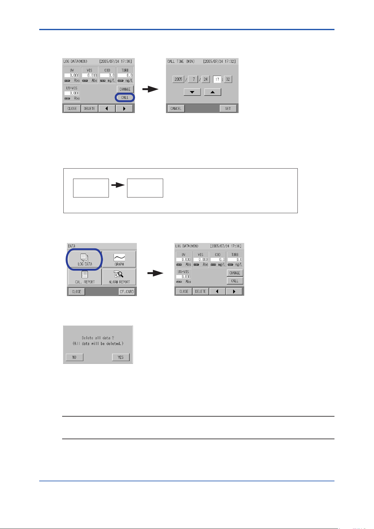
<6. Functions>
[CALL]
[LOG DATA]
1. Press [CALL].
The CALL TIME (MIN / HOUR) screen appears.
2. Select the hour to be chanted and set the number by using [m] and [.]. After entering the
number, press [SET].
The LOG DATA screen with the specied data and time appears.
6.8.2 Log Data Deletion
[DATA]
6-23
MEAS.
screen
Refer to “6.8 Data Screen Display”
1. Press the [[LOG DATA] on the DATA screen.
The LOG DATA screen appears.
2. Press the [DELETE] on the LOG DATA screen.
The “Delete all data?” screen appears.
DATA
screen
3. Press [YES].
The screen returns back to the LOG DATA screen.
Log data deletion is complete.
NOTE
When executing a deletion on the LOG DATA (MIN) screen: all (MIN) log data deleted.
When executing a deletion on the LOG DATA (HOUR) screen: all (HOUR) log data is deleted.
IM 12K01B02-01E
Page 81

<6. Functions>
[GRAPH]
[UV]
6.8.3 GraphDisplay
[DATA]
6-24
MEAS.
screen
Refer to “6.8 Data Screen Display”
1. Press the [GRAPH] on the DATA screen.
The SELECT COMP. screen appears.
The screens show examples for UV.
2. Press the measurement component to be checked.
The GRAPH screen appears.
DATA
screen
NOTE
[START TIME (DATE)]: Changes the start time of the graph.
[◀][▶]: Switches to the previous and next data.
[SET]: Changes the range of vertical and horizontal axes.
l Changingthestarttimeofthegraph
1. Press the [START TIME (DATE)].
The CALL TIME (MIN / DATE) screen appears.
2. Select the hour to be changed and set the number by using [m] and [.]. After entering the
number, press [SET].
The screen returns back to the GRAPH screen.
IM 12K01B02-01E
Page 82
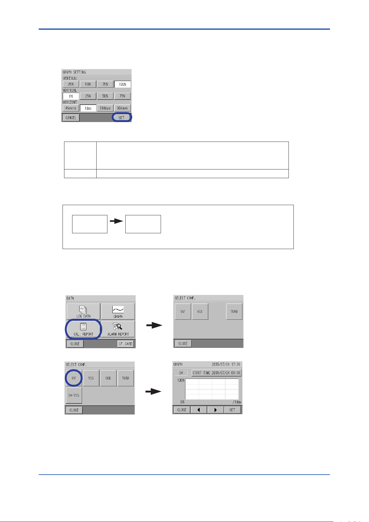
<6. Functions>
l Changingtherangeverticalandhorizontalaxes
1. Press the [SET] button.
The [GRAPH SETTING] screen appears.
2. Select the range from VERTICAL / VERTICAL / HORIZONE, and press [SET].
VERTICAL
(UPPER)/
VERTICAL
(LOWER)
HORIZONE:
% indicates the proportion of the graph range in relation to the measurement range.
"4 hours / 1 day" indicate the (MIN) data. "10 days / 30 days" indicate the (HOUR) data.
6.8.4 CalibrationReportCheck
6-25
[DATA]
MEAS.
screen
DATA
screen
Refer to “6.8 Data Screen Display”
The calibration report can be checked here.
1. Press the [CAL. REPORT] on the DATA screen.
The SELECT COMP. screen appears.
The screens show examples for UV.
[CAL.
REPORT]
2. Select the measurement component to be checked.
[UV]
The CAL. REPORT screen appears.
Up to 20 calibration dates and zero / span factors are displayed by measurement
component and by zero / span in chronological order from the latest date.
Refer to “5.1 ◦ About the Calibration coecient”
IM 12K01B02-01E
Page 83
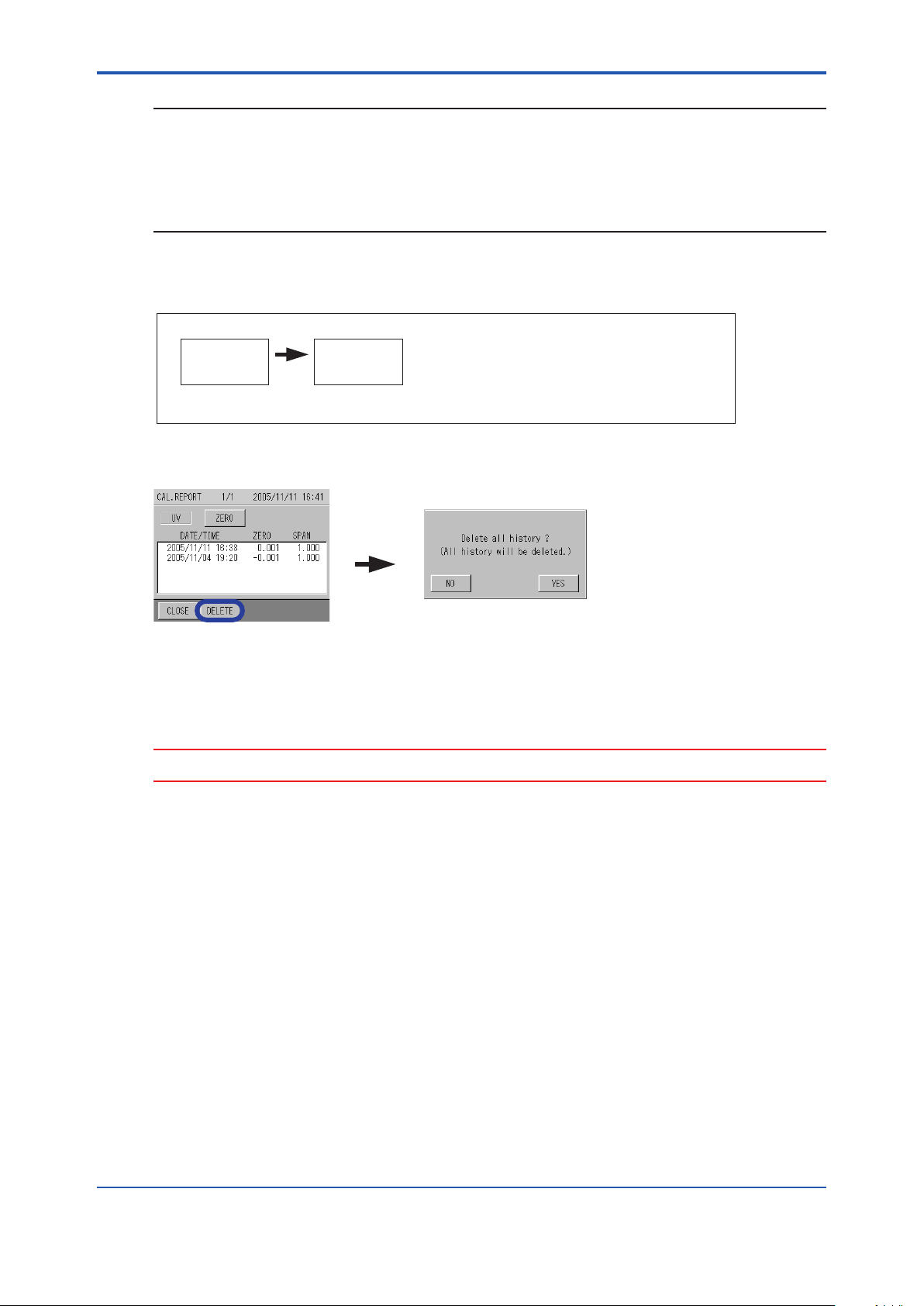
<6. Functions>
NOTE
[ZERO] / [SPAM]: Switches between ZERO CAL. REPORT and SPAN CAL. REPORT.
[◀][▶]: Switches to the previous and next data.
[DELETE]: Deletes all of the calibration report.
When changing the measurement component to display, press [◀] to go back to the SELECT
COMP. screen.
6.8.5 Calibration Report Deletion
[DATA]
6-26
MEAS.
screen
Refer to “6.8 Data Screen Display”
1. Press the [DELETE] on the CAL. REPORT screen.
The CAL. REPORT screen appears.
2. Press [YES].
The screen returns back to the CAL. REPORT screen. Calibration report deletion is
complete.
DATA
screen
[DELETE]
CAUTION
Though all of the calibration report is deleted, the latest calibration value is memorized.
IM 12K01B02-01E
Page 84
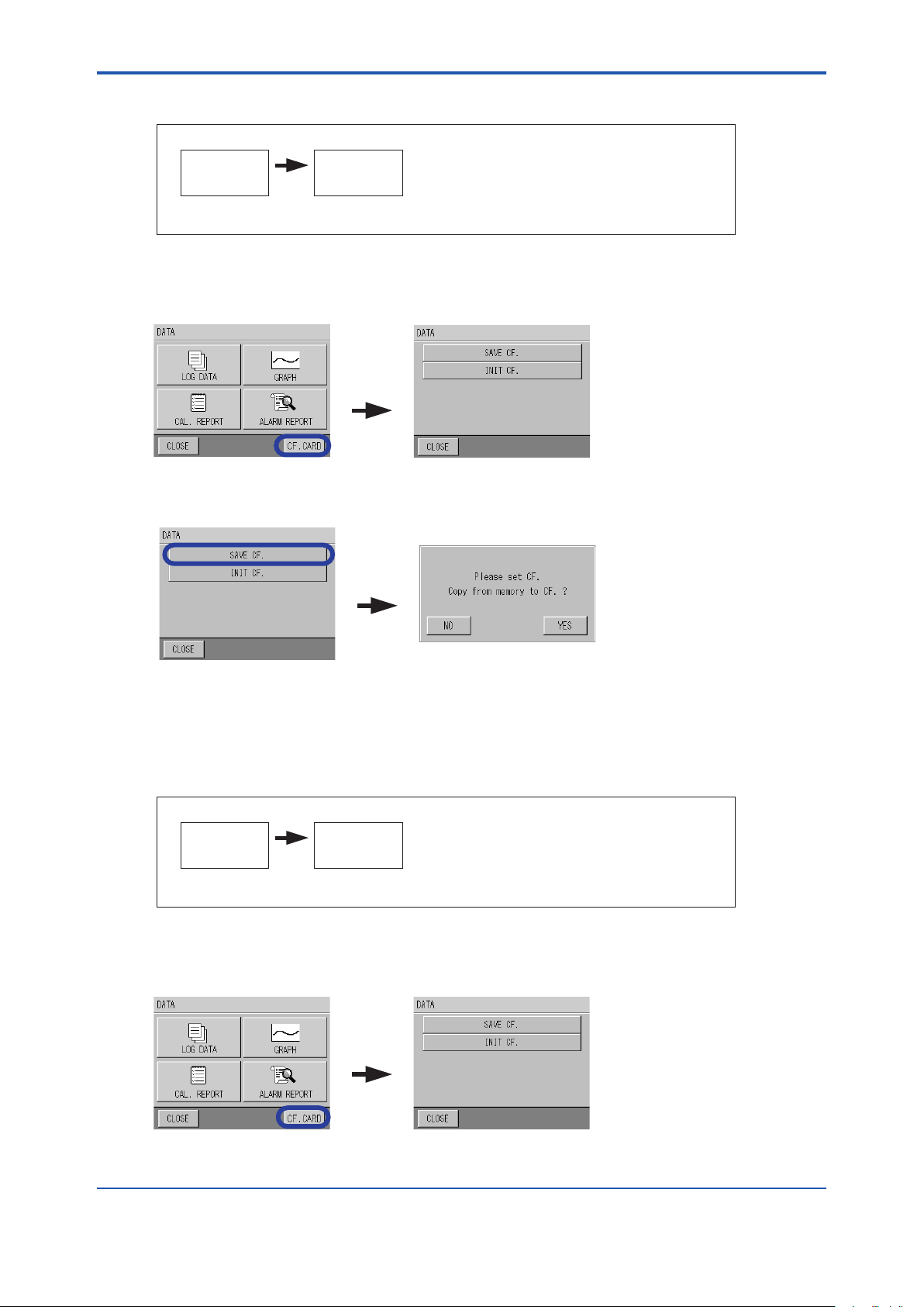
<6. Functions>
6.8.6 CFCardTransfer
[DATA]
6-27
MEAS.
screen
Refer to “6.8 Data Screen Display”
Data can be transferred to a CF card.
1. Press the [CF. CARD] on the DATA screen.
The CF CARD menu screen appears.
2. Press [SAVE CF.].
The CF card transfer screen appears.
DATA
screen
[CF.CARD]
[SAVE CF.]
3. Conrm that the CF card is inserted, and press [YES].
The transferring screen appears.
When the transfer is complete, the screen returns back to the CF CARD menu screen.
6.8.7 CFCardInitialization
[DATA]
MEAS.
screen
Refer to “6.8 Data Screen Display”
The CF card can be initialized here.
1. Press the [CF. CARD] on the DATA screen.
The CF CARD menu screen appears.
DATA
screen
[CF.CARD]
IM 12K01B02-01E
Page 85
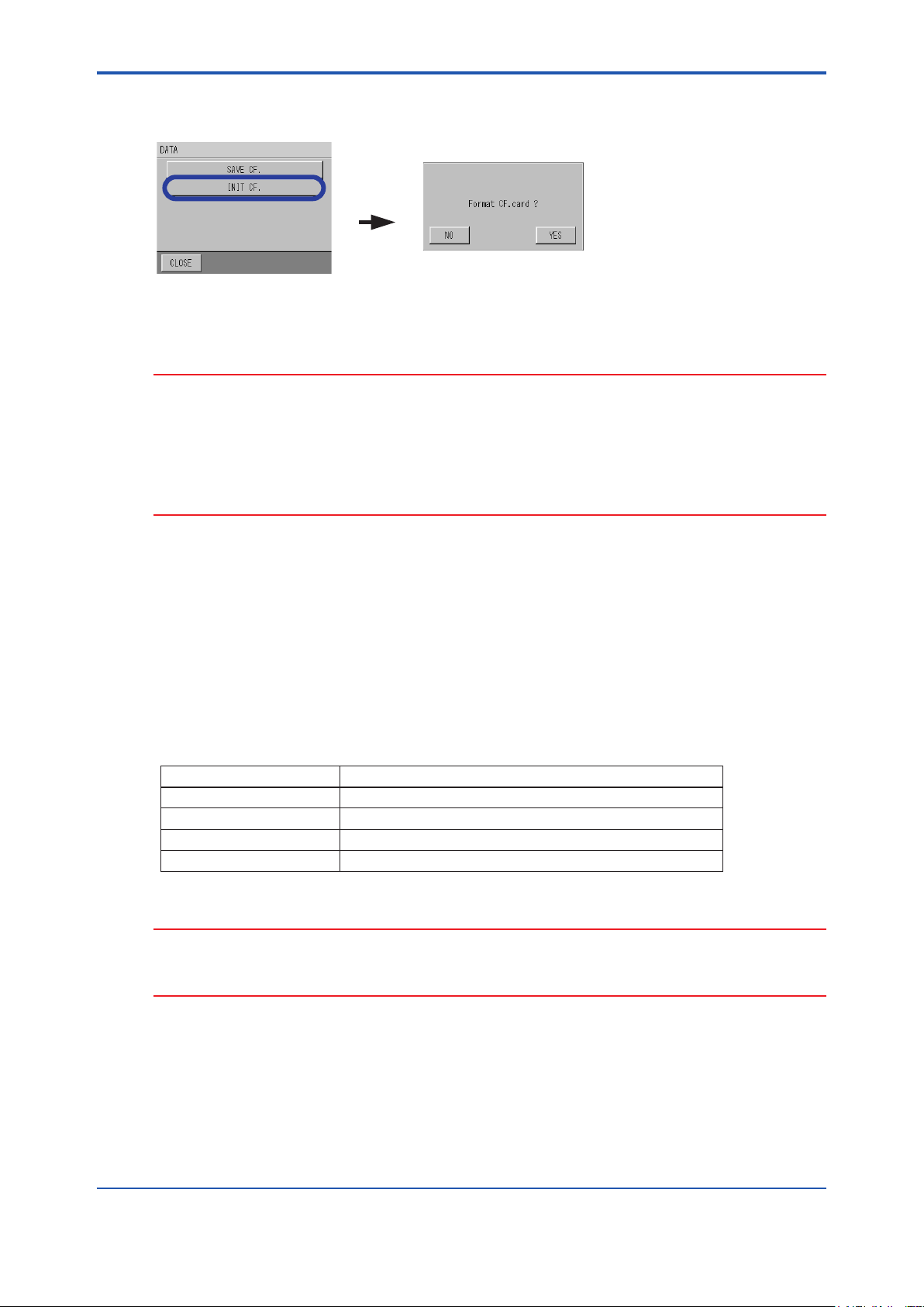
<6. Functions>
2. Press [INIT CF.].
The screen to initialize the CF card appears.
[INIT CF.]
3. Conrm that the CF card is inserted, and press [YES].
When the initialization is complete, the screen returns to the CF CARD menu screen.
CAUTION
• When the CF card is initialized, all the data of CF card is deleted. Make sure to save the
contents before executing initialization.
• Execute initialization of the CF card using this unit.
• The le system of this unit is FAT. FAT32 and NTFS are not accepted.
• Use only genuine Yokogawa CF card (P/N K9436 CF). Otherwise, proper operation is not
guaranteed.
6-28
6.9 Alarm
An alarm is triggered when a malfunction occurs in the unit or the measurement value exceeds
the upper or lower limit.
Refer to “9.1 Table of Status and Operation”
Items regarding alarm are as follows:
Items of alarm
Alarm Check (6.9.1) Performs a check during the alarm.
Alarm Stop (6.9.2) Stops all alarms during the alarm.
Alarm History Check (6.9.3) Checks the alarm history of up to 511 records.
Alarm History Deletion (6.9.4) Deletes all of the alarm history.
CAUTION
As this unit calculates values using one digit under the least signicant digit indicated as readings
or setting values, an alarm may not be triggered even if the displayed value is the same value set
for alarm.
Description
IM 12K01B02-01E
Page 86
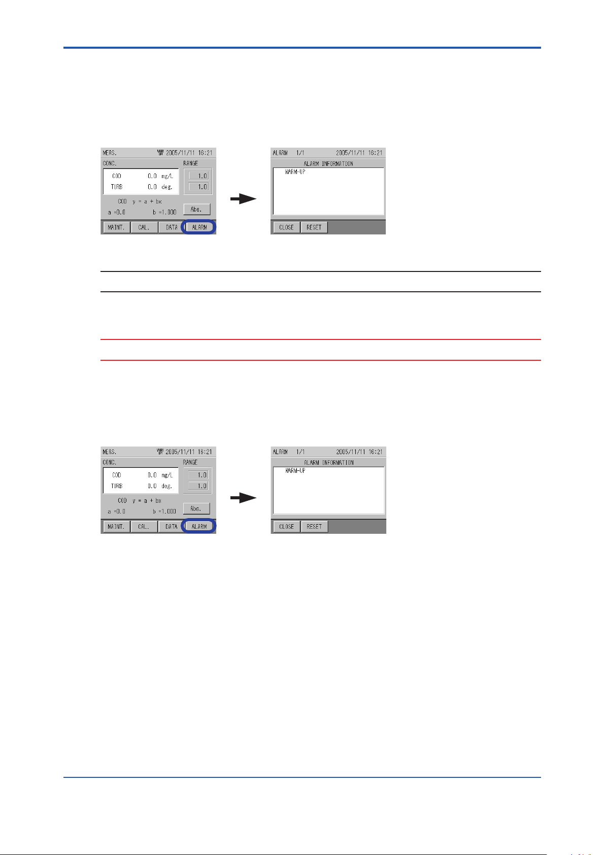
<6. Functions>
6.9.1 AlarmCheck
The instant alarm can be checked here.
1. Press the [ALARM] on the MEAS. screen (main screen).
The ALARM screen appears.
The alarm information is displayed.
[ALARM]
NOTE
[RESET]: Stops the alarm.
6-29
CAUTION
If an instant alarm is not triggered, the ALARM button is not displayed.
6.9.2 Alarm Stop
1. Press the [ALARM] on the MEAS. screen (main screen).
The ALARM screen appears, and the alarm information is displayed.
2. Press [RESET].
The alarm stop screen appears.
3. Press [YES].
The screen returns back to the ALARM screen.
Alarm stop is complete.
[ALARM]
IM 12K01B02-01E
Page 87
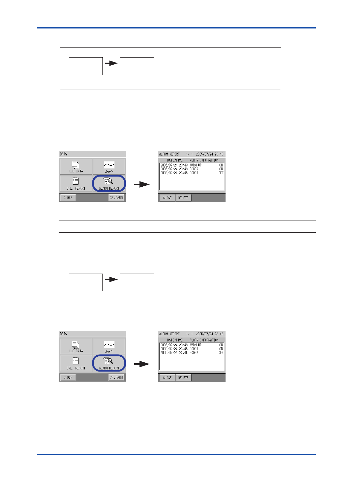
<6. Functions>
6.9.3 AlarmHistoryCheck
[DATA]
6-30
MEAS.
screen
Refer to “6.8 Data Screen Display”
The history of past alarms can be checked here.
1. Press the [ALARM REPORT] on the DATA screen.
The ALARM REPORT screen appears.
Alarm information, date / time, and ON / OFF are displayed.
If “ON” is displayed, the information when the alarm was triggered is shown, and if “OFF” is
displayed, the information when the alarm was released is shown.
DATA
screen
[ALARM
REPORT]
NOTE
[DELETE]: Deletes the alarm history.
6.9.4 Alarm History Deletion
[DATA]
MEAS.
screen
Refer to “6.8 Data Screen Display”
1. Press the [ALARM REPORT] on the DATA screen.
The ALARM REPORT screen appears.
2. Press [DELETE].
The alarm history deletion screen appears.
3. Press [YES].
The screen returns back to the ALARM REPORT screen.
DATA
screen
[ALARM
REPORT]
The alarm history deletion is complete.
IM 12K01B02-01E
Page 88
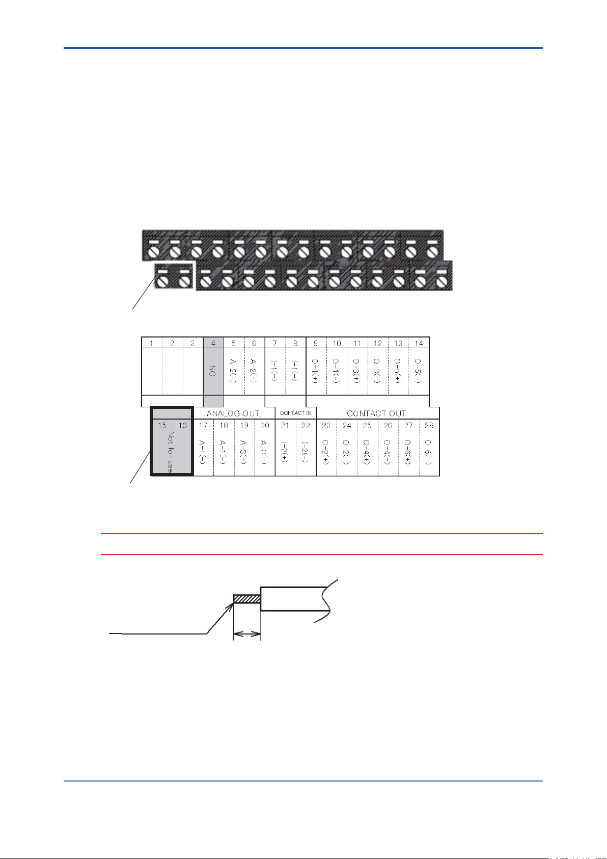
<7. External Input and Output>
7. ExternalInputandOutput
This unit contains the terminals for contact input/output, analog output. These terminals should
be used when the status input, alarm signal output, measurement value signal
output, and remote signal input are required.
7.1 Terminal diagram of input and output
The input/output terminal diagram is shown below.
Input/output terminals are the green terminals under the converter.
1 2 3 4 5 6 7 9 9 10 11 12 13 14
15 16 17 18 19 20 21 22 23 24 25 26 27 28
7-1
Not for use
Not for use Terminal table
Terminal No.
CAUTION
Do not connect the signal line to terminals No. 15 and 16 as they are connected internally.
Perform terminal processing of
0.08mm2 to 1.5mm
(
AWG28 to AWG16)
2
7mm
the signal line as shown in the figure.
Terminal processing of signal line
IM 12K01B02-01E
Page 89
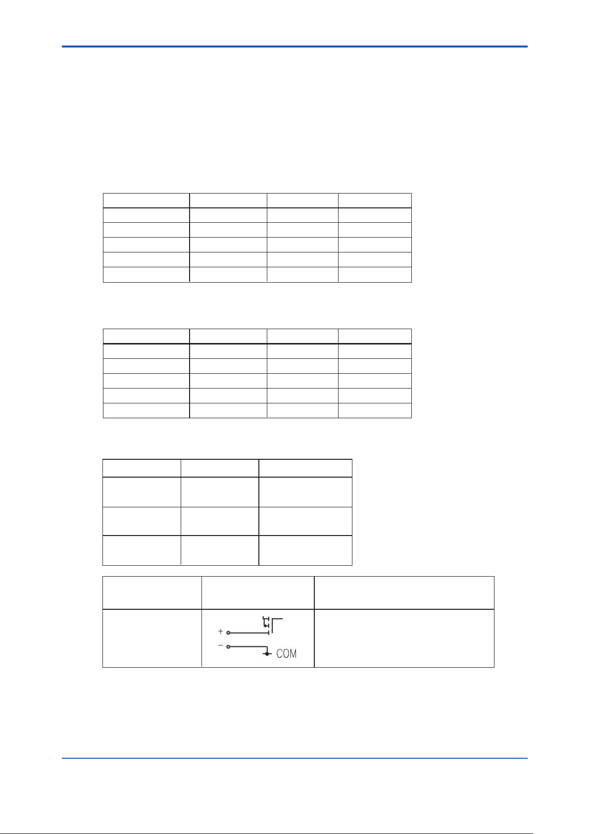
<7. External Input and Output>
7.2 Analog Output
This unit outputs the measurement value by analog current output when outputting to the
outside.
The analog output contains three outputs, and outputs by selecting three components
from the following ve components.
The output value is output in conjunction with the full scale of each measurement value.
l Measurementitemandanalogoutputrange:exampleof4to20mAoutput
7-2
Measurement item
UV
VIS
UV-VIS
COD
TURB (turbidity)
Range (example) 4 mA output
1 Abs
1 Abs
1 Abs
100 mg/L
100 mg/L
0 Abs
0 Abs
0 Abs
0 mg/L
0 mg/L
20 mA output
1 Abs
1 Abs
1 Abs
100 mg/L
100 mg/L
l Measurementitemandanalogoutputrange:exampleof0to16mAoutput
Measurement item
UV
VIS
UV-VIS
COD
TURB (turbidity)
Allocations for measurement analog output terminals are as follows:
Specications for analog current output are as follows:
Terminal No. Output No.
17
18
5
6
19
20
Range (example) 0 mA output
1 Abs
1 Abs
1 Abs
100 mg/L
100 mg/L
A-1(+)
A-1(-)
A-2(+)
A-2(-)
A-3(+)
A-3(-)
0 Abs
0 Abs
0 Abs
0 mg/L
0 mg/L
Allocation
(Arbitrary setting)
(Arbitrary setting)
(Arbitrary setting)
16 mA output
1 Abs
1 Abs
1 Abs
100 mg/L
100 mg/L
Refer to “6.4.1 Signal Allocation”.
IM 12K01B02-01E
Signal type
Analog signal output
Input and output
circuit
Specifications
•
DC 0 mA to 16 mA/4 mA to
20 mA Current signal output
•
Insulated output (common to COM)
•
Load resistance: Max. 600 Ω
Page 90

<7. External Input and Output>
7.3 Contact Input and Output
7.3.1 Contact Output
This unit incorporates the contact output as shown below.
The contact point output contains 6 outputs, and 4 outputs can be set arbitrarily apart from
POWER OFF and MAINTENANCE.
Item Output No. Description Output timing
TOTAL ALARM Arbitrary setting Indicates various alarm
except POWER OFF.
ANALYZE ERR. Arbitrary setting Indicatesan analyzer
malfunction.
LAMP ERR. Arbitrary setting Indicates a UV lamp
malfunction.
MOTOR ERR. Arbitrary setting Indicates a wiper motor
malfunction.
NO SAMPLE Arbitrary setting Indicates there is no
sample.
MAX COD Arbitrary setting Indicates the upper
alarm limit for COD.
MIN COD Arbitrary setting Indicates the lower
alarm limit for COD.
MAX TURB Arbitrary setting Indicates the upper
alarm limit for TURB.
MIN TURB Arbitrary setting Indicates the lower
alarm limit for TURB.
WARM-UP Arbitrary setting Indicates the unit is
warning up.
POWER OFF O-5 (fixed) Indicates power OFF. ON when the power is turned OFF. (short circuit)
MAINTENANCE O-6 (fixed) Indicates the unit is
in maintenance, or
calibration mode.
ON when 1 or more alarms except POWER OFF, MAINTENANCE,
and NO SAMPLE have been triggered. (short circuit)
OFF when all alarms are stopped except POWER OFF,
MAINTENANCE, and NO SAMPLE. (open)
ON when an analyzer has malfunctioned. (short circuit)
OFF when all the analyzer malfunctions are canceled. (open)
ON when the light intensity of the UV lamp is less than the specified
value. (short circuit)
OFF when the light intensity of UV lamp is over the specified value.
(open)
ON when motor rotation is abnormal (short circuit)
OFF when motor rotation is normal. (open)
ON when the water level of the overflow tank has decreased and float
switch is activated for 5 seconds continuously. (short circuit)
OFF when the water level of overflow tank has increased and float
switch is canceled for 5 seconds continuously. (open)
ON when the status "COD measurement value > COD MAX
ALARM VALUE" continues longer than the specified alarm time.
(short circuit)
OFF when the status "COD measurement value < COD MAX
ALARM VALUE" continues longer than the specified alarm time.
(open)
ON when the status "COD measurement value < COD MIN ALARM
VALUE" continues longer than the specified alarm time. (short
circuit)
OFF when the status "COD measurement value > COD MIN ALARM
VALUE" continues longer than the specified alarm time. (open)
ON when the status "TURB measurement value > TURB MAX
ALARM VALUE" continues longer than the specified alarm time.
(short circuit)
OFF when the status "TURB measurement value < TURB MAX
ALARM VALUE" continues longer than the specified alarm time.
(open)
ON when the status "TURB measurement value < TURB MIN
ALARM VALUE" continues longer than the specified alarm time.
(short circuit)
OFF when the status "TURB measurement value > TURB MIN
ALARM VALUE" continues longer than the specified alarm time.
(open)
ON for 1 hour after turning the power ON. (short circuit)
OFF after 1 hour has passed since turning the power ON. (open)
OFF when power OFF is canceled. (open)
ON during maintenance mode or calibration mode, or when the
maintenance switch is ON. (short circuit)
OFF when not in-maintenance mode or calibration mode, or when the
maintenance switch is OFF. (open)
7-3
IM 12K01B02-01E
Page 91
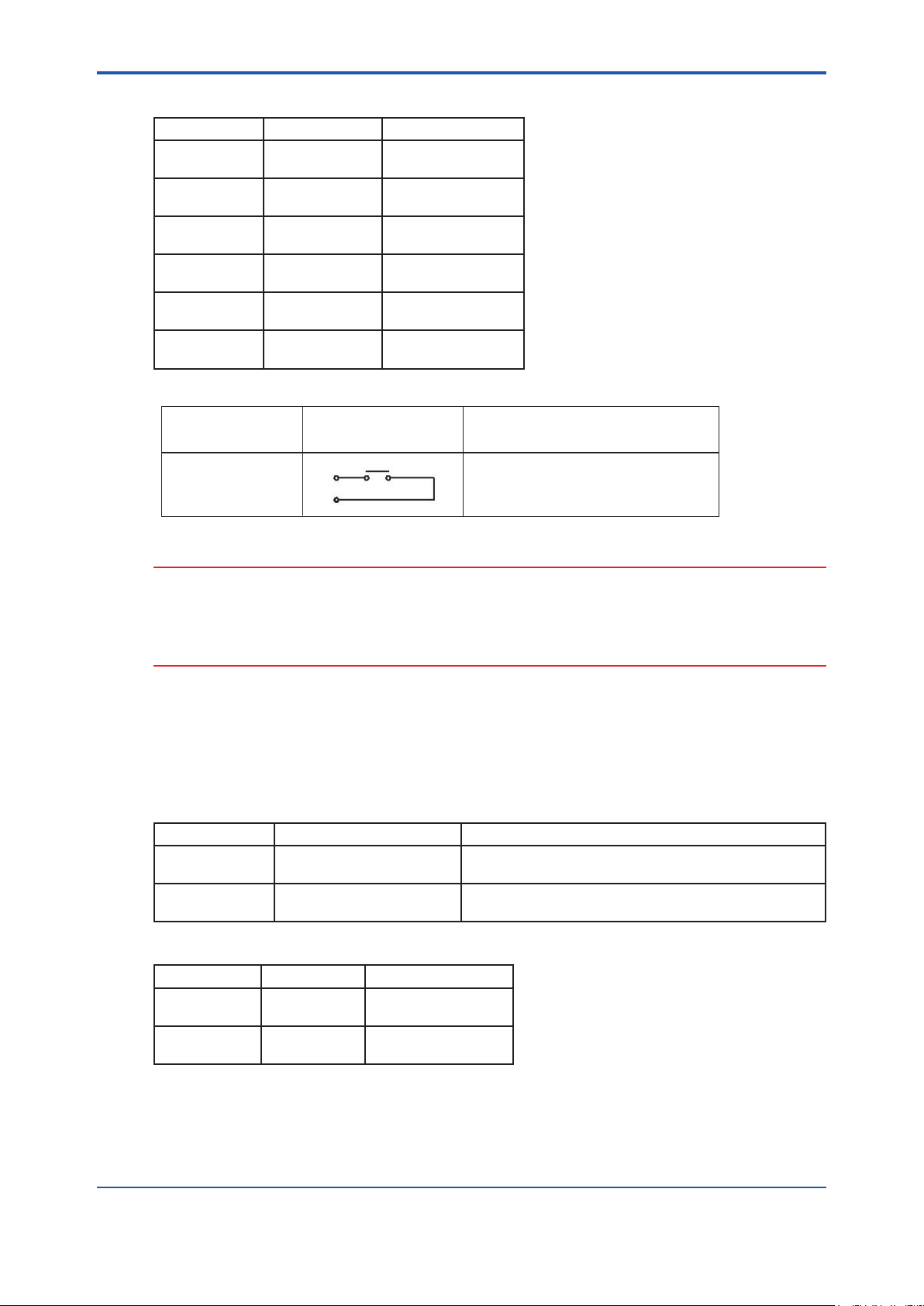
<7. External Input and Output>
Allocations for contact output terminals are as follows:
Terminal No. Output No. Allocation
9
10
23
24
11
12
25
26
13
14
27
28
O-1(+)
O-1(-)
O-2(+)
O-2(-)
O-3(+)
O-3(-)
O-4(+)
O-4(-)
O-5(+)
O-5(-)
O-6(+)
O-6(-)
(Arbitrary setting)
(Arbitrary setting)
(Arbitrary setting)
(Arbitrary setting)
POWER OFF
MAINTENANCE
Specications for contact output are as follows:
7-4
Input and output
Contact signal output
CAUTION
• Do not apply a load over the maximum rating. Doing so may cause a malfunction.
• When switching the load, connect the spark killer, surge absorber (AC or DC load), diode
(DC load) etc. in parallel to prevent noise.
• “a” contact output: OFF normally (open), ON during operation (short circuit)
Refer to “6.4.1 Signal Allocation”
7.3.2 Contact Input
This unit is equipped with contact inputs as shown below. They are enabled when set to the
contact point,
Item Description Input timing
NO SAMPLE
FLOAT SWITCH
TIME
CORRECTION
Detects NO SAMPLE
using the built-in oat switch.
Accepts time corrections. Accepts time corrections when turned ON (short circuit) for
circuit
SpecificationsSignal type
l
Contact rating: AC 125V 0.3A
DC 30V 1A
l
a contact output
Starts when turned ON (short circuit) for more than 5
seconds after being OFF (open).
3 to 10 seconds after being OFF (open)
Allocations for contact input terminals are as follows:
IM 12K01B02-01E
Terminal No. Output No. Allocation
7
8
21
22
I-1(+)
I-1(-)
I-2(+)
I-2(-)
Float switch
Input time correction
Page 92

<7. External Input and Output>
Specications for contact input are as follows:
Signal type Input and output circuit Specications
● “a” contact signal input without
voltage (open collector output is
Contact signal input
Photo
coupler
possible)
● ON resistance: Max. 100 V
● Open voltage: 5.5 V DC
● Short circuit current: Max. 5 mA
CAUTION
• Never connect wiring with voltage to the input terminal. Doing so may cause malfunction.
• If the input timing is less than 3 seconds, the contact input may not be accepted.
Make sure to allow more than 3 seconds for contact ON time.
7.4 SavingDatatoaCFCard
7-5
This unit enables the transfer of saved internal data using a CF card, and the verication
of the data on a PC etc. The CF card is available optionally.
CAUTION
• Make sure to use the CF card produced by YOKOGAWA. We cannot guarantee normal
operation when using other products.
• The le system of this unit is FAT. FAT32 and NTFS are not accepted.
l HowtosavetoaCFcard
Refer to “6.8.6 CF Card Transfer”
Refer to “6.8.7 CF Card Initialization”
l FoldercongurationtobesavedontheCFcard
A second folder is created, which is named according to the date and hour of the data transfer,
within the rst folder where individual ID numbers are named.
Example:
When the individual ID number is “12345678” and the data is transferred at 18 o’clock
“12345678” folder
“04102218” folder
“05060701” folder
IM 12K01B02-01E
Page 93

<7. External Input and Output>
l DatatobesavedontheCFcard
Saves the data with the following le names in the created folder.
1 hour data history: HDATA.CSV
1 minute data history: MDATA.CSV
Alarm history: ALMDATA.CSV
Zero calibration history: ZERO.CSV
Span calibration history: SPAN.CSV
Internal RAM data: RAMDATA.CSV
The above data les are saved on the CF card simultaneously.
l Data Information
Each le is in the CSV (comman separated value) format, and a label line is on the rst line.
The label meanings are as follows:
(HDATA.CSV)
7-6
Label name Description
YY/MM/DD/HH:MM:SS year/month/date/hour:minute:second
UV UV
VIS VIS
COD COD
TURB TURB
UV-VISL UV-aVIS
DataStat Data status (determined by each bit) *1
AlmUV UV data alarm (determined by each bit) *2
AlmVIS VIS data alarm (determined by each bit) *2
AlmCOD COD data alarm (determined by each bit) *2
AlmTURB TURB data alarm (determined by each bit) *2
AlmUVVIS UV-aVIS data alarm (determined by each bit) *2
The data is in hexadecimal notation. Convert the hexadecimal notation to binary notation
according to the conversion table, and determine the values (“1” is ON and “0” is OFF) by
referring to each digit (bit) of each table from the left.
Conversiontable,hexadecimalnotationtobinarynotation
Hexadecimal
notation
Binary
notation
0 1 2 3 4 5 6 7 8 9 A B C D E F
0000 0001 0010 0011 0100 0101 0110 0111 1000 1001 1010 1011 1100 1101 1110 1111
*1: Data status
Alarm
Bit0: invalid data
Bit1: maintenance
Bit2: with NO power
Bit3: spare
IM 12K01B02-01E
Page 94

<7. External Input and Output>
Bit4: calibration
Bit5: spare
Bit6: sub, initialization
Bit7: sampling output hold
Bit8 to 16: spare
Bit17: alarm 001 (warm-up)
Bit18: spare
Bit19: alarm 003 (cell-motor operation error)
Bit20: alarm 004 (inside communication error)
Bit21: alarm 005 (no sample)
Bit22: alarm 006 (inside communication error (I2C))
Bit23: alarm 007 (power ON alarm)
Bit24: alarm 008 (battery cell-motor alarm)
Bit25: alarm hold 009 (light source malfunction)
Bit26 to 31: spare
Example)If“DataStat”is“00800006”;
1. Convert the hexadecimal notation to a binary notation.
7-7
After converting, 0 to 0000, 0 to 0000, 8 to 1000, and so on,
“0000/0000/1000/0000/0000/0000/0000/0110” is obtained.
2. Apply the binary notation value to the bit table from the left.
Bit
Binary notation value
Hexadecimal notation value
31 30 29 28 27 26 25 24 23 22 21 20 19 18 17 16 15 14 13 12 11 10 9 8 7 6 5 4 3 2 1 0
0 0 0 0 0 0 0 0 1 0 0 0 0 0 0 0 0 0 0 0 0 0 0 0 0 0 0 0 0 1 1 0
0 0 8 0 0 0 0 6
“1” in binary notation is ON. Data status is as follows:
Bit23: alarm 007 (power ON alarm)
Bit2: with NO power
Bit1: maintenance
*2: Data alarm
Determine by conversion using the same method as *1
Bit0: alarm 0n0 (abnormal upper limit of concentration)
Bit1: alarm 0n1 (abnormal lower limit of concentration)
Bit2: spare
Bit3: spare
Bit4: spare
Bit5: alarm 0n5 (zero calibration error)
Bit6: alarm 0n6 (span calibration error)
Bit7 to 11: spare
Bit12: maintenance output data
Bit13: warm-up output data
Bit14: spare
Bit15: alarm output data
IM 12K01B02-01E
Page 95

<7. External Input and Output>
(MDATA.CSV)
Same as HDATA.CSV
(ALDATA.CSV)
Label name Description
YY/MM/DD/HH:MM:SS year/month/date/hour:minute:second
AlmNo Alarm No.
DataStat Data status: ON, OFF
(ZERO.CSV)
[UV]: UV data
[VIS]: VIS data
Label name Description
YY/MM/DD/HH:MM:SS year/month/date/hour:minute:second
CalbNo
CalbStat Calibration result: OK, NG
CalbConc Calibration value
CoeffiZero Zero calibration coefficient
CoeffiSpan Span calibration coefficient
"Calibration No.
(M: manual calibration, A: automatic
calibration)"
7-8
(SPAN.CSV)
[UV]: UV data
[VIS]: VIS data
[TURB]: TURB (turbidity) data
CAUTION
If the names of les or folders are the same, they shall be overwritten.
(RAMDATA.CSV)
Saves the internal setting table.
(Exclusive for service personnel)
IM 12K01B02-01E
Page 96
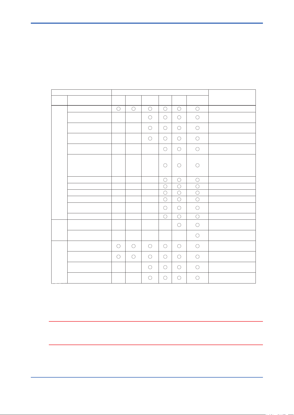
<8. Maintenance>
8 Maintenance
Calibration and periodical maintenance are required in order to maintain the normal operation
and performance of the unit.
Regarding calibration, refer to “5 Calibration”
8.1 Maintenance item
8-1
Maintenance item Recommended Maintenance cycle
Subject Description Weekly Monthly
Cleaning of measuring cell When dirt can be seen.
Inspection and replacement
of wipers
Replacement of desiccant
agent in analyzing case
Replacement of desiccant
agent in measuring cell
Replacement of inner parts
Analyzer
unit
Replacement of UV lamp
Replacement of motor Periodical replacement (yearly)
Replacement of seal washers Periodical replacement (yearly)
Replacement of V-rings Periodical replacement (yearly)
Replacement of gear Periodical replacement (yearly)
Replacement of cell
Replacement of case packing Periodical replacement (yearly)
Replacement of battery for
clock
Control
unit
Replacement of substrate and
electric parts
Cleaning of measuring tank
Sampling
Cleaning of overflow tan
unit
Cleaning of piping
Cleaning of ball valve
Every
half year
Yearly
Every
3 years
Accordingly
Referece of Time
to clean/replace
When dirt can be seen.
Periodical replacement
(every half year)
Periodical replacement
(every half year)
When the measurement
value is abnormal
Periodical replacement (yearly)
When the measurement value
is abnormal
When the UV lamp does not
illuminate
When dirt can be seen
When it is damaged
Periodical replacement
(every 3 years)
When malfunctioning
When dirt can be seen
When clogged
When dirt can be seen
When clogged
When dirt can be seen
When clogged
When dirt can be seen
When clogged
The maintenance cycle in the table is the typical interval when using under standard conditions,
and does not guarantee the measurement values. They may vary according to the circumstances
or usage conditions set the proper cycle after using for a certain period of time.
CAUTION
Maintenance items for which the maintenance period is over 1 year are not described in this
manual.
These should be performed by YOKOGAWA service personnel.
IM 12K01B02-01E
Page 97
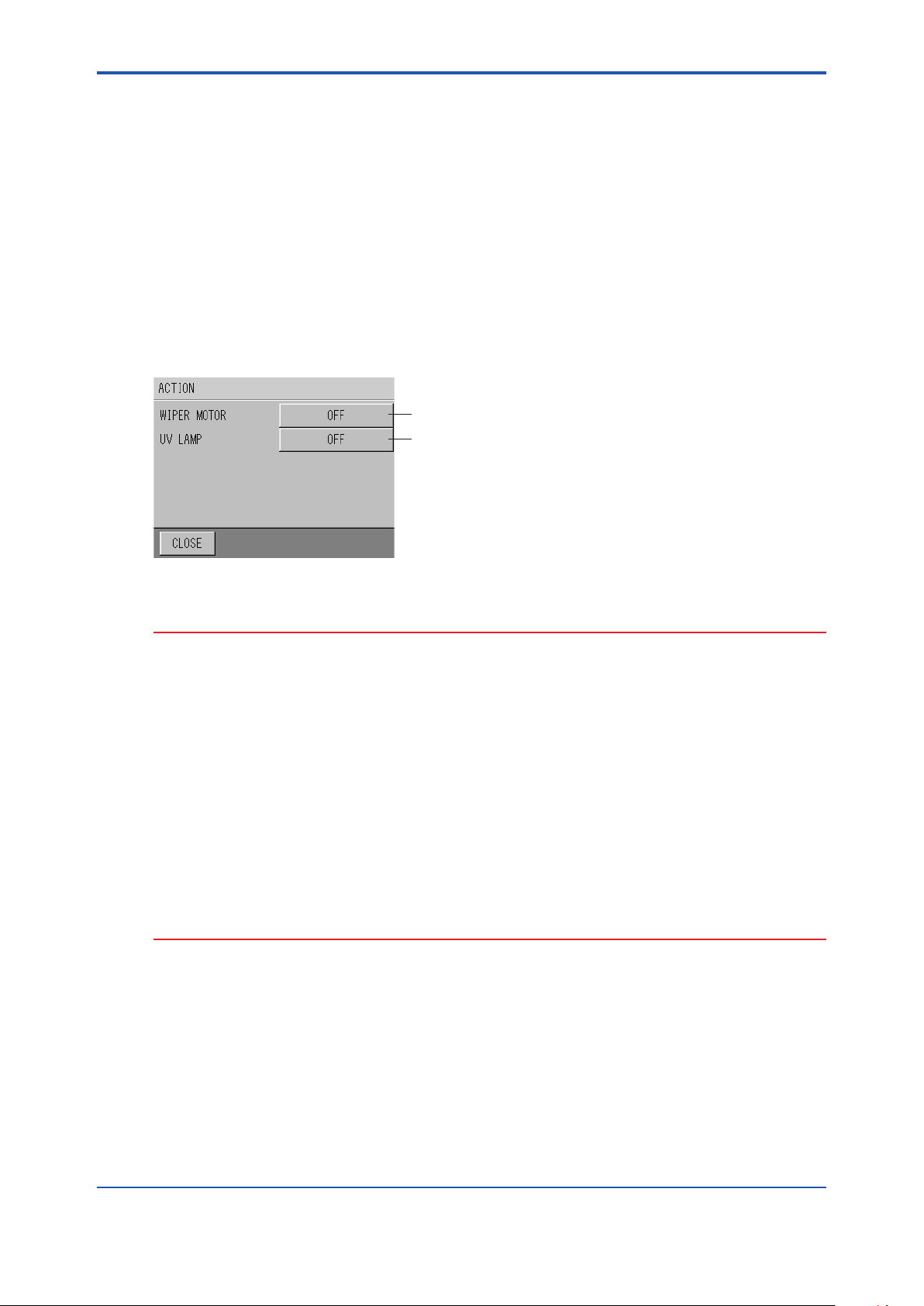
<8. Maintenance>
8.2 Maintenance of Detector
8.2.1 CleaningMethodforMeasuringCell
Here describes the cleaning method of the measuring cell in the detector.
Perform maintenance approximately once a week.
Perform this maintenance work with the power ON.
1. Turn the maintenance switch ON.
2. Press the [ACTION] button on the MAINTENANCE screen.
Refer to “6.6.1 Action”
3. Turn the wiper motor ON and UV lamp OFF.
ON
OFF
8-2
4. Remove the detector from the measuring tank.
CAUTION
• When the wiper motor is operating, take care to handle so that ngers etc. are not caught in
the motor.
• Care should be taken when handling the cell of detector so that it does not touch other parts
of the unit.
• Before performing the work, conrm that the UV lamp is not illuminated. The UV lamp
should not be viewed directly when it is illuminated as it may damage your eyes.
• If the MAINTENANCE – ACTION screen is not touched (backlight is not turned on) for about
2 hours, the screen will return to the MEASUREMENT screen. When the screen is touched
once and the backlight is turned on, the timer will be reset and the screen will not return to
the MEASUREMENT screen until about 2 hours have elapsed.
• Note that the screen will return to the MAINTENANCE screen and automatically the wiper
motor and UV lamp will be turned on if no buttons are pressed for 30 minutes on the
MAINTENANCE – ACTION screen. When any button is pressed within 30 minutes, the
timer will be reset and actions will be performed as specied on the screen until 30 minutes
have elapsed.
IM 12K01B02-01E
Page 98
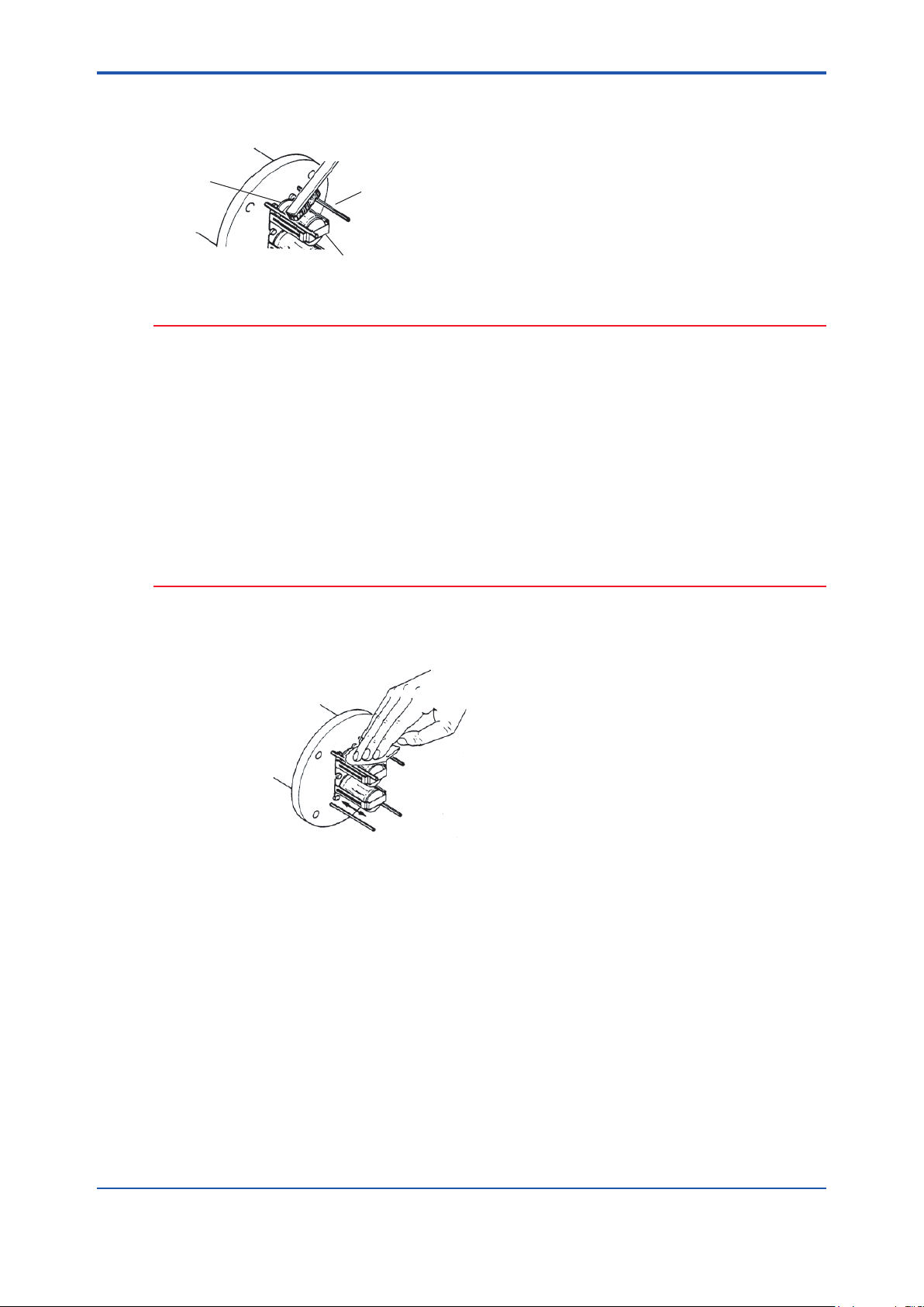
<8. Maintenance>
5. Scrape o the contamination or alga adhered to the peripheral parts such as wiper clamp,
base, or roller around the cell.
Brush
8-3
Roller
Wiper clamp
Base
CAUTION
• Never scrape the cell (glass part) with a brush. The cell may be damaged.
• While cleaning, never tilt the detector 80 degrees or more from vertical.
• Never leave the detector standing alone. Put the detector on the calibration tank when not
using the measuring tank, for safe and easy handling.
• The measuring cell is made of glass. Handle with great care so as not to break the glass.
• Clean the wiper within a few minutes. If operating the wiper without any solution for a long
period of time, it may damage the cell.
• Note that the screen will return to the MAINTENANCE screen and automatically the wiper
motor and UV lamp will be turned on if no buttons are pressed for 30 minutes on the
MAINTENANCE – ACTION screen. When any button is pressed within 30 minutes, the
timer will be reset and actions will be performed as specied on the screen until 30 minutes
have elapsed.
6. Wipe o the rotating cell to remove contamination with a clean, wet cloth by moving it up
and down lightly. Wipe to remove contamination by moving up and down.
Wipe to remove contamination by moving up and down.
7. Thoroughly clean the cell and peripheral parts using the cleaning bottle or small amount of
tap water. In this case, do not put any solution on the base of cell rotary shaft (V-ring seal
part).
8. Dip the detector in the calibration tank of zero solution.
9. Press the [CLOSE] button of the converter several times to return to the MEASUREMENT
screen.
10. Warm up the unit for approximately 60 minutes, replace the zero solution, and perform zero
calibration.
Refer to “5.4.2 Common Zero Calibration”
11. Perform span calibration as necessary.
Refer to “5.4.3 Common Span Calibration”
IM 12K01B02-01E
Page 99
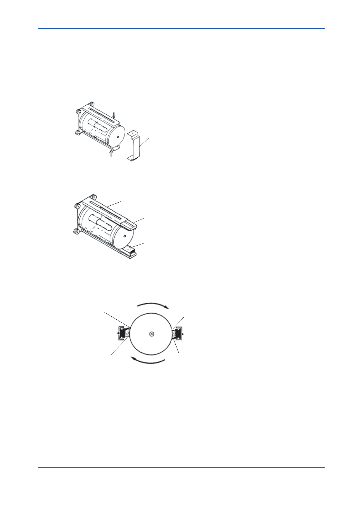
<8. Maintenance>
8.2.2 Replacement of Wiper Blade Rubber
Here describes the replacement of wiper blade rubber of measuring cell.
1. Turn ON the maintenance switch.
2. Turn OFF the power switch.
3. Remove the detector from the measuring tank and remove the xing brackets (2) of the cell
unit.
Press inward.
Bracket
Press inward.
4. Pinch the wiper blade rubber with long-nose pliers etc. and remove it by pulling inward and
downward.
8-4
Wiper blade
Wiper blade rubber
Sponge
5. Insert the new wiper blade rubber in the reverse order to step 4. Ensure a correct installing
direction so that the wiping parts or the wiper blade rubber are located in the direction of cell
rotation when viewing from the bottom.
Direction of cell rotation
Wiping part of wiper
blade rubber
Sponge
Sponge
Wiping part of wiper
blade rubber
6. Install the bracket in its original place.
7. Put the detector back in the measuring tank.
8. Turn the power switch ON.
9. Press the [ACTION] button on the MAINTENANCE screen.
Refer to “6.6.1 Action”
IM 12K01B02-01E
Page 100

<8. Maintenance>
10. Turn the wiper motor ON and UV lamp OFF.
ON
OFF
11. Remove the detector from the measuring tank and conrm that the replaced wiper blade
rubber and sponge are in contact with the cell and the wiper blade wiping smoothly. If the
wiper blade is misaligned or the rotation is not smooth, repeat wiper blade installation from
step 5.
CAUTION
• As the wiper motor is operating, take care to handle so that ngers etc. are not caught in the
motor.
• Take care in handling the cell of detector so that if does not touch other parts of the unit.
• Before performing the work, conrm that the UV lamp is not illuminated. The UV lamp
should not be viewed directly when it is illuminated as it may damage your eyes.
• If no button is pressed for about two hours on the MAINTENANCE - ACTION display, the
display automatically turns to the MEASUREMENT display. In this case, care should be
taken as the wiper motor and UV lamp may turn ON.
• Clean the wiper within a few minutes. If operating the wiper without any solution for a long
period of time, it may damage the cell.
• If the MAINTENANCE – ACTION screen is not touched (backlight is not turned on) for about
2 hours, the screen will return to the MEASUREMENT screen. When the screen is touched
once and the backlight is turned on, the timer will be reset and the screen will not return to
the MEASUREMENT screen until about 2 hours have elapsed.
• Note that the screen will return to the MAINTENANCE screen and automatically the wiper
motor and UV lamp will be turned on if no buttons are pressed for 30 minutes on the
MAINTENANCE – ACTION screen. When any button is pressed within 30 minutes, the
timer will be reset and actions will be performed as specied on the screen until 30 minutes
have elapsed.
8-5
12. Dip the detector in the calibration tank of zero solution.
13. Warm up the unit for approximately 60 minutes, replace the zero solution, and perform zero
calibration.
Refer to “5.4.2 Common Zero Calibration”
14. Perform span calibration as necessary.
Refer to “5.4.3 Common Span Calibration”
IM 12K01B02-01E
 Loading...