

Page 1
<<Contents>> <<Index>>
General
Specifications
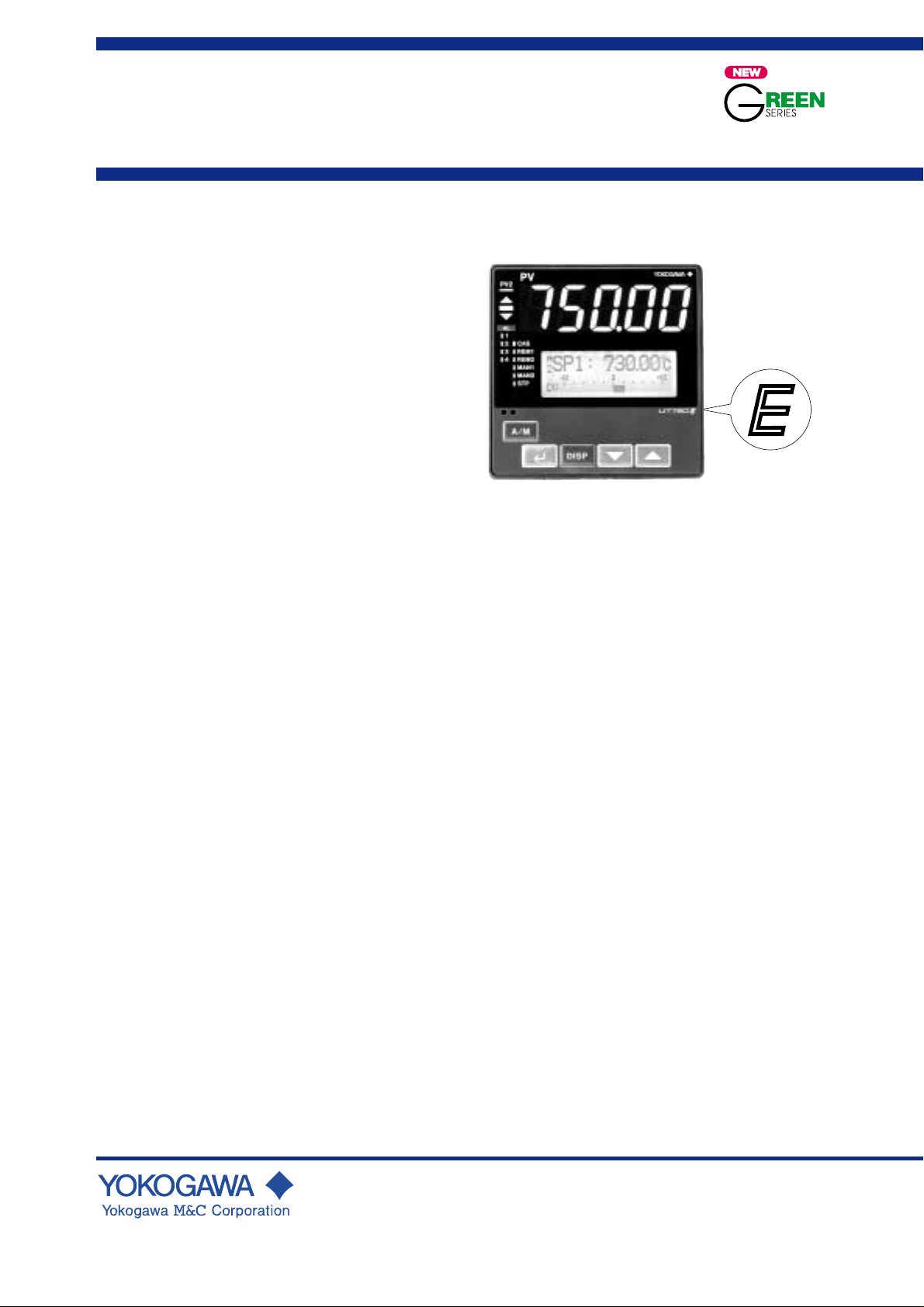
MODEL UT750
Digital Indicating Controller
(with Custom Computation)
GS 05D01B02-01E
■ General
Model UT750 Digital Indicating Controller is an intelligent,
micro-processor based digital indicating controller with
powerful control capability, custom computation function
and the user-friendly large numerical display. The UT750
features many functions which are necessary for various
control application as standard, and all of these functions
such as control function, control computation function,
signal computation function, etc. can be configured by using
the keys on the front panel. The instrument specifies thirteen
types of control strategies built in and also the overshoot
suppressing function "SUPER" and a hunting suppressing
function "SUPER 2" as well as an auto-tuning as standard.
■ Main Features
• Extra-large digital display allows the indicated values to be
read even from a long distance. LEDs of 20 mm height are
used for the process variable display. This is a five-digit
display for higher resolution.
• User-friendly full dot LCD display. Not only the target
setpoint and other control related parameters but also a
deviation trend record or a deviation analogue bar can be
displayed.
• Thirteen types of control function, including single-loop
control, cascade control, loop control with PV autoselector, and custom computation control, enabling the
operator to start control operation immediately after simply
entering the settings.
• Custom Computation function, which allows users’ own
configuration for signals, enable them to realize such
functions as complicated computation for input compensation or sequence logic.
( “Custom Computation Building Tool <model name:
LL200> is necessary to use this function.)
• Universal input and output enable users to set or change
freely the type of measured inputs (thermocouple, RTD, or
DCV), measurement input range, type of control output (4
to 20mA current, voltage pulse, or relay contact), etc. from
the front panel.
• Equipped with seven contact inputs and outputs each,
which are further expandable up to 23 inputs and outputs
each by adding contact I/O signal expansion modules.
• Various communication function are provided.
Communication is possible with personal computer,
programable logic controller, and other controllers.
■ Functional Specifications
● Control Functions
UT mode
The following types of basic control structure can be set as
the UT mode by the user.
Single-loop Control (UT mode 1):
The most simple and basic control function.
UT750
UT750E
“E” indicates with the
model with expanded
functions.
Cascade primary-loop control (UT mode 2):
Output tracking function and cascade control
logic are provided. Suitable for the primaryloop cascade control.
Cascade secondary-loop control (UT mode 3):
Setpoint output and cascade control logic are
provided. Suitable for the secondary-loop
cascade control.
Cascade control (UT mode 4):
Dual control function for cascade control is
available in a single instrument.
Loop control for back up (UT mode 5):
Output tracking function is provided to backup another control instrument. The switching
between its control output and the control
output of the instrument to be backed-up can
be carried out by external contact.
Loop control with PV switching (UT mode 6):
Two measured inputs are switched for control
depending on the status of contact input or
measured input.
Loop control with PV auto-selector (UT mode 7):
Two measured inputs are automatically
selected for control with a high, low, average,
or temperature-difference value selector.
Dual-loop control (UT mode 11):
Dual control function is available in a single
instrument to control two loop.
Temperature and Humidity control (UT mode 12):
Temperature and Relative Humidity control is
available in a single instrument.
Cascade control with two universal inputs (UT mode 13):
Cascade control with using two universal
measured inputs.
Loop control with PV switching and two universal inputs
(UT mode 14):
Loop control with PV switching and two
universal inputs available as measured inputs.
GS 05D01B02-01E
© Copyright Feb. 2000 (YK)
1st Edition Mar. 2000 (YG)
Page 2

<<Contents>> <<Index>>
2
Loop control with PV auto-selector and two universal
inputs (UT mode 15):
Process variable for loop control is automatically selected from two or three measured
inputs by an internal selector, with using two
universal inputs and an auxiliary analogue
input. When two universal inputs are
configured as measured input, auxiliary
analog input can be used for a remote setting
input.
Custom computation control (UT mode 21):
Can be provided by the user using the optional
LL200 custom computation building tool.
● Control Computation Functions
In each UT mode, the following control computation
functions can be selected.
Continuous PID control, Time-proportional
PID control, Position proportional PID
control(UT750-1 ■ position-proportional type
only), Relay ON/OFF control, Heating/
Cooling control.
Target setpoint and PID parameter:
Maximum eight sets of target setpoint and PID
parameters can be set and stored in a instrument. For Cascade control and Dual Loop
control type, eight sets for each main and
slave are available.
Zone PID selection:
Sets of PID parameters can be selected
according to PV zone. Maximum seven zones
can be set for selection.
Auto-tuning:
Available as standard.
Possible to activate auto-tuning for both loops
of Cascade control, Dual-loop control, and
Temperature and humidity control.
“SUPER” function:
Overshoots generated by abrupt changes in the
target setpoint or by disturbances can be
suppressed.
“SUPER 2” function:
The function stabilizes the state of control that
is unstable due to hunting, etc. without
requiring any change in PID constants, when
the load and/or gain varies greatly, or when
there is a difference between the characteristics of temperature zones.
Preset output function:
When the instrument is in STOP mode,
measured input is burnout, or abnormality is
found in an input circuit, users’
preconfigurable preset value is output as a
control output.
Control cycle time:
Each cycle time can be selected under the
following coditions
50ms: Available when model code is "UT750-00",
UT mode is set to Single-loop control, and
the following function is not used. “SUPER” function, “SUPER 2” function,
Heating/Cooling control, measured input
computations, setpoint rate of change
limiter, output rate of change limiter,
deviation alarm, sensor grounding alarm,
fault-diagnosis alarm, FAIL output.
100ms: Available when model code is UT750-0 ■,
UT750-1 ■, (Without Cascade control)
200ms: Available when model code is UT750-5 ■
and the amount of computation module of
Custom computation function is less than
30.
500ms: Available when the amount of computation
module of Custom computation function is
more than 30.
(Set value on shipped from the factory: 200ms)
Operation Mode Switching
(Note: Communication enables all the
following mode switching to be excuted.)
AUTO/MANUAL switching:
Bump-less switching is available. Switching
between AUTO and MANUAL mode can be
realized by using front key or by external
contact, and external contact switching has
priority to a front key operation.
When UT mode is set to “Cascade secondaryloop control” or “Cascade control”, switching
can not be realized by external contact.
RUN/STOP switching:
Switching of RUN/STOP can be realized by
external contact. Bump-less switching from
STOP to RUN is available. In RUN mode,
control computation is activated. In STOP
mode, control computation is ceased and
preset output value is output as a control
output, while other functions are operated
normally.
REMOTE/LOCAL switching:
Switching between local setpoints and remote
setpoint can be realized by instrument
operation or external contact, and external
contact switching is prior to instrument
operation. For remote to local switching,
either with bump-less tracking ( to make the
local setpoint value equivalent to the Remote
setpoint value upon switching.) or without
tracking(to switch directly to local setpoint in
the instrument) can be specified by the
parameter.
CASCADE/AUTO/MANUAL switching:
Switching can be realized by instrument
operation or external contact, and external
contact switching is prior to instrument
operation. Available when UT mode is set to
“Cascade secondary-loop control” or
“Cascade control” .
Output tracking ON/OFF switching:
Available when UT mode is set to “Cascade
primary-loop control” or “ Loop control for
back-up”. Switching between External
tracking signal and internal control output can
be realized by external contact.
Control Parameter Setting Range
Proportional band: 0.1 to 999.9%
0.0 to 999.9% (for heating/cooling control.),
0.0% available for ON/OFF control
Integral time: 1 to 6,000 s, or OFF (for Manual reset)
Derivative time: 1 to 6,000 s, or OFF
ON/OFF control hysteresis:
0.0 to 100.0% of measured input range width
Preset output value: -5.0 to 105.0% of Output range
(0mA or less cannot be output)
All Rights Reserved. Copyright © 2000, Y okogawa M&C Corporation
GS 05D01B02-01E 1st Edition Mar. 31, 2000-00
Page 3

<<Contents>> <<Index>>
3
Output limiter:
Setting range: -5.0 to 105.0% for both high
and low limits.
However, “low limit setpoint < high limit
setpoint” must be satisfied.
When heating/cooling PID control, upper
limiter for heating and upper limiter for
cooling.
Shutdown function(For 4 to 20 mA control output only):
In manual mode operation, up to approx. 0mA
can be output.
Rate of change limiter for output:
OFF, or 0.1 to 100.0%/s
Dead band of heating/cooling control:
-100.0 to 50.0% of Output value
Dead band of position-proportional control:
1.0 to 10.0 % of Output value
● Configuration of Input/Output Signal
Measured Input Computations
Bias(-100.0 to 100.0% of measuring input range), First lag
filter(OFF, 1 to 120 s), Square root extraction(for voltage
input only, Input low cut 0.0 to 5.0%), 10-segment linearizer
function, 10-segment bias function, relative humidity
calculation by wet/dry bulb(for Temperature & Humidity
control type)
Auxiliary Input Computations
Applicable for remote setting input only.
Bias(-100.0 to 100.0%), First lag filter (OFF, 1 to 120s),
Square root extraction (Input low cut 0.0 to 5.0%),
Ratio multiplication (0.001 to 9.999)
Custom Computations
LL200 Building tool is necessary to use Custom computation
function.
Combining computation function modules allows such
functions as users’ own configuration of input/output signals,
operation mode switching via contact input, and status output
via contact output.
Computation function module:
Addition/subtraction/multiplication/division,
Processing absolute value/reciprocal,
Selecting maximum/minimum/average,
Keeping maximum/minimum value, Keeping
value, Rate of change limiter, Switch, Limiter,
Constant, AND, OR, Exclusive OR, NOT,
Latch, Comparison (=,<,>,,), Not
equivalent, Within range, AND(word),
OR(word), Shift word, Sum, Timer, Tensegment linearizer 1/2, Inverse ten-segment
linearizer 1/2, Curve linearizer 1/2, Ratio,
First order lag filter, Conversion to industrial
unit, Selection of PV from two inputs,
Temperature and humidity calculation, MV
selection1/2, Conversion of display value,
Parameter setting, Data display1/2, Special
contact output calculation, Assignment of
output terminals 1/2, etc.
Maximum usable Number of Module:
Input custom computation 50
Output custom computation 50
● Alarm Functions
Alarm types:
PV high limit, PV low limit, Deviation high
limit, Deviation low limit, Deenergized on
deviation high limit, Deenergized on deviation
low limit, Deviation high and low limits, High
and low limits within deviation, Deenergized
on PV high limit, Deenergized on PV low
limit, SP high limit, SP low limit, Output high
limit, Output low limit.
Alarm setting range:
PV/SP alarm: -100 to 100 % of measured
input range
Deviation alarm: -100 to 100 % of measured
input range width
Output alarm: -5.0 to 105.0% of output value
Alarm hysteresis: 0.0 to 100.0 % of measured
input range width
Delay timer:
0.00 to 99.59 (minute, second)
An alarm is output when the delay timer
expires after the alarm setpoint is reached.
Setting for each alarm is possible.
Stand-by action:
Stand-by action can be set to make PV/
deviation alarm OFF during start-up or after
SP change unitl SP reaches the normal region.
Timer function (stabilization of control status notification
event) (Alarm 1 only):
The timer function sets alarm 1 output to ON/
OFF when preset time is elapsed after PV has
reached to the SP and its hysteresis band.
Activated again by RUN/STOP switching or
SP switching.
Other alarm actions:
Sensor grounding alarm: Detects sensor
deterioration and outputs an alarm.
Fault diagnostic alarm: Input burnout, A/D
conversion error, RJC error.
FAIL output: Abnormality in software, or
Abnormality in hardware.
Number of alarm settings: 4 points (for each loop)
Alarm output points: 4 points
Up to 4 points can be selected among PV,
deviation, SP, output sensor grounding, fault
diagnosis and FAIL alarms and output.
Timer function is available with alarm 1
output only.
Note: See the Hardware Specifications and the contents of
Contact Outputs described later.
● Display and Operation Functions
PV Display Unit
Either PV1 or PV2 can be displayed on 5 digit digital display
unit and switched one from the other.
Digit of display is 4 or 5 digit. For Thermocouple and RTD
input, Lower digit than decimal point can be turned off.
The display range is -19999 to 30000 and the display span is
30000 or less. [750.00 appearing in the product photograph
on page 1 cannot actually be displayed.]
All Rights Reserved. Copyright © 2000, Y okogawa M&C Corporation GS 05D01B02-01E 1st Edition Mar. 31, 2000-00
Page 4
<<Contents>> <<Index>>
4
LCD Display Unit
Some data are displayed on LCD display unit. Each screen is
called “display”.
Four types of displays are provided. Operating display,
Operating parameter setting display, setup parameter setting
display, and SELECT display.
Each screen of LCD display unit
Operating display:
Necessary data for operation is displayed
according to UT mode. Such items as
Setpoint, Control output, Control output bargraph, deviation trend, and deviation analogue
bar-graph are displayed. Memorable time of
deviation trend is 120 s to 20 h.
Operating parameters setting display:
The Operating parameters, which are mainly
changed during operation, such as PID
constant, are displayed.
Setup parameter setting display:
The Setup parameters to configure the
functions of the instrument before starting
operation are displayed.
UT mode is set in this display.
Status lamps
Second PV (PV2), deviation (▲,
Alarm (AL1,2,3,4), Cascade (CAS),
Remote (REM1,REM2),
Manual (MAN1,MAN2), Stop (STP)
Communication port for light loader
Communicate with the tool on the PC to transfer
the setting data of parameters / Custom
computation.
■
, ▼ )
SELECT display:
Up to 5 displays which are frequently
accessed can be selected from the Operating
parameter setting display and Setup para-
meters setting display to be displayed in the
SELECT display.
Status Lamps
Alarm indicating lamp: 4 points(AL1,AL2,AL3,AL4)
Operation mode indicating lamp:
PV 2 (PV of Loop 2), REM 1 (Remote
operation of Loop 1), REM 2 (Remote
operation of Loop 2), MAN 1 (Loop 1 in
Manual mode operation), MAN 2 (Loop 2 in
Manual mode operation), STP (Operation is
ceased), CAS (Cascade operation)
Deviation indicating lamp:
䉱 Plus deviation , 䉲 Minus deviation, and
deviation in normal range
Deviation band for the display can be set.
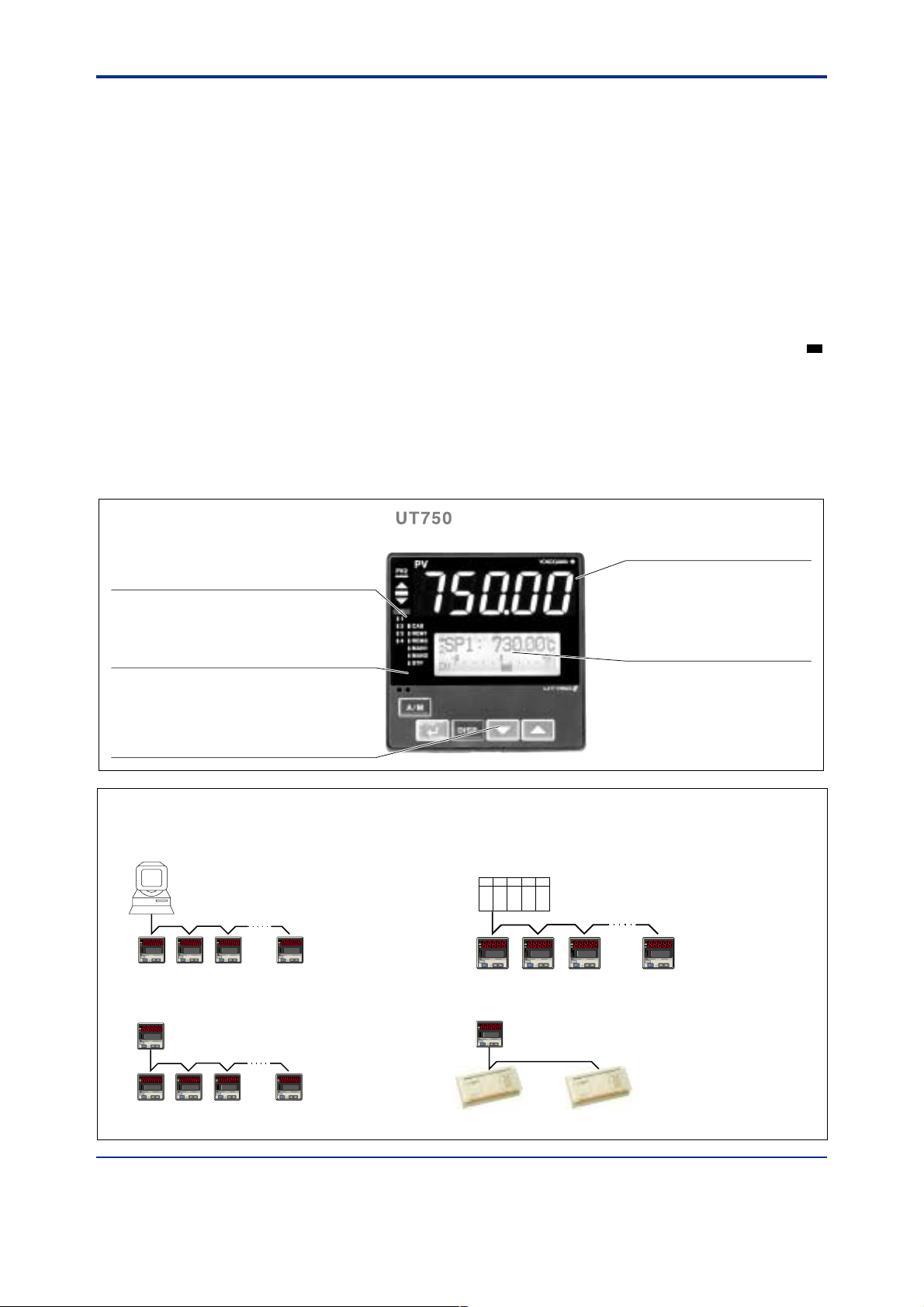
LED display unit (for PV)
Display PV, and error code when
error is detected.
LCD display unit
Display setpoint (SP), output value,
deviation bargraph, deviation value,
deviation trend, valve opening and
setting item/value of parameters.
Operation keys
Increase/Decrease the setting data (䉭, 䉮)
Switching the display (DISP)
Select parameter/Enter the setting data (SET/ENT)
A/M mode switching of Loop 1 (A/M).
Examples of Communication System Configuration Diagram
(1) Computer link communication/
MODBUS communication
Personal computer
PV
PV
PV2
AL
1
2
3
REM
4
MAN1
MAN2
STP
CAS
A/M
DISP
SET/ENT
PV
PV2
PV2
AL
AL
1
1
2
2
3
3
REM
REM
4
4
MAN1
MAN1
MAN2
MAN2
STP
STP
CAS
CAS
A/M
A/M
DISP
DISP
SET/ENT
SET/ENT
PV
PV2
AL
1
2
3
REM
4
MAN1
MAN2
STP
CAS
A/M
DISP
SET/ENT
UT750 Digital indicating controller
(3) Coordinated operation
PV
PV2
AL
1
2
UP750 Program controller
3
REM
4
MAN1
MAN2
STP
CAS
A/M
DISP
SET/ENT
or UT750 Digital indicating controller
PV
PV
PV2
AL
1
2
3
REM
4
MAN1
MAN2
STP
CAS
A/M
DISP
SET/ENT
PV
PV2
PV2
AL
AL
1
1
2
2
3
3
REM
REM
4
4
MAN1
MAN1
MAN2
MAN2
STP
STP
CAS
CAS
A/M
A/M
DISP
DISP
SET/ENT
SET/ENT
PV
PV2
AL
1
2
3
REM
4
MAN1
MAN2
STP
CAS
A/M
DISP
SET/ENT
UT750 Digital indicating controller
(2) Ladder communication
MELSEC-A
PV
PV2
AL
1
2
3
REM
4
MAN1
MAN2
STP
CAS
A/M
DISP
SET/ENT
UT750 Digital indicating controller
(4) Digital I/O Expansion Module (µ-BUS communication)
PV
PV2
AL
1
UT750
2
3
REM
4
MAN1
MAN2
STP
CAS
A/M
DISP
SET/ENT
Digital Indicating Controller
D I/O Expansion module
Programmable logic
controller
PV
PV2
AL
1
2
3
REM
4
MAN1
MAN2
STP
CAS
A/M
PV
PV2
AL
1
2
3
REM
4
MAN1
MAN2
STP
CAS
A/M
DISP
SET/ENT
DISP
SET/ENT
PV
PV2
AL
1
2
3
REM
4
MAN1
MAN2
STP
CAS
A/M
DISP
SET/ENT
All Rights Reserved. Copyright © 2000, Y okogawa M&C Corporation
GS 05D01B02-01E
1st Edition Mar. 31, 2000-00
Page 5
<<Contents>> <<Index>>
5
Operation Keys
䉭, 䉮 key: Increases/decreases the value of Setpoints or
other parameters which appear on LCD display.
DISP key: Switch data to be showed on LCD display
SET/ENT key: Set/change the setting value, switch
contents to be showed on LCD display, switch
operation mode other than AUTO/MAN.
A/M key: Switch operation mode (AUTO/MAN)
Security Function
Key lock from parameter setting and operation
can be inhibited by a password.
● Communication Functions
( For UT750- ■1 only )
The instrument has two communication port and five types
of communication protocols, and allows the simultaneous
communication with two different instruments.
The instruments to communicate are a personal computer, a
programmable logic controller, and other UT750/UP750.
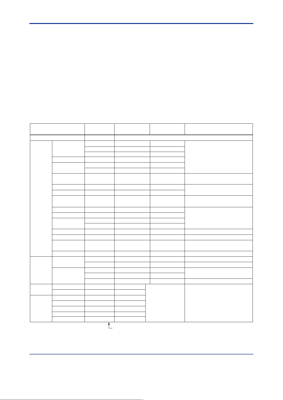
Input type
Unspecified (When shipped from the factory)
Thermocouple
RTD
Standard
signal
DC voltage
K
J
T
B
S
R
N
E
L (DIN)
U (DIN)
W (DIN)
Platinel 2
PR20-40
W97Re3-W75Re25
JPt100
Pt100
0.4 to 2V
1 to 5V
0 to 2V
0 to 10V
0.0 to 1.2 V (Note 3)
-10 to 20mV
0 to100mV
Input range
code
typeK1 (1)
typeK2 (2)
typeK3 (3)
typeJ (4)
typeT1 (5)
typeT2 (6)
typeB (7)
typeS (8)
typeR (9)
typeN (10)
typeE (11)
typeL (12)
typeU1 (13)
typeU2 (14)
typeW (15)
plati2 (16)
PR2040 (17)
W97Re3 (18)
JPt1 (30)
JPt2 (31)
Pt1 (35)
Pt2 (36)
Pt3 (37)
0.4 to 2V (40)
1 to 5V (41)
0 to 2V (50)
0 to 10V (51)
0.0 to 1.2 V
mV1 (55)
mV2 (56)
OFF
Instrument
range (°C)
Set the data item PV input type “IN 1” to the OFF option to leave the PV input type undefined.
-270.0 to 1370.0°C
-270.0 to 1000.0°C
-200.0 to 500.0°C
-200.0 to 1200.0°C
-270.0 to 400.0°C
0.0 to 400.0°C
0.0 to 1800.0°C
0.0 to 1700.0°C
0.0 to 1700.0°C
-200.0 to 1300.0°C
-270.0 to 1000.0°C
-200.0 to 900.0°C
-200.0 to 400.0°C
0.0 to 400.0°C
0.0 to 2300.0°C
0.0 to 1390.0°C
0.0 to 1900.0°C
0.0 to 2000.0°C
-200.0 to 500.0°C
-150.00 to 150.00°C
-200.0 to 850.0°C
-200.0 to 500.0°C
-150.00 to 150.00°C
0.400 to 2.000 V
1.000 to 5.000 V
0.000 to 2.000 V
0.00 to 10.00 V
0.000 to 1.200 V
-10.00 to 20.00 mV
0.0 to 100.0 mV
Communication Protocol
Computer link communication:
Ladder communication:
Coordinated operation protocol:
MODBUS communication:
Digital input/output expansion (µ-Bus):
Instrument
-450.0 to 2500.0°F
-450.0 to 2300.0°F
-200.0 to 1000.0°F
-300.0 to 2300.0°F
-450.0 to 750.0°F
-200.0 to 750.0°F
-300.0 to 2400.0°F
-450.0 to 1800.0°F
-300.0 to 1600.0°F
-300.0 to 750.0°F
-200.0 to 1000.0°F
32.0 to 2500.0°F
-300.0 to 1000.0°F
-200.0 to 300.0°F
-300.0 to 1560.0°F
-300.0 to 1000.0°F
-200.0 to 300.0°F
Display range
-19999 to 30000
Display span 30000 or
less (Decimal point
position changeable)
Communication protocol with a personal
computer.
Communication protocol with the ladder
program on some programmable logic
controllers.
Protocol to realize Coordinated operation
with other GREEN SERIES controller.
UT750 can be configurated as either master
or slave unit.
Communication protocol with a personal
computer or PLC.
Protocol to connect Digital I/O expansion
module to increase the number of Discrete
Input and Output.
range (°F)
32 to 3300°F
32 to 3100°F
32 to 3100°F
32 to 4200°F
32 to 3400°F
32 to 3600°F
Instrument accuracy
±0.1% ±1 digit of instrument range at 0°C or more
±0.2% ±1 digit of instrument range at less than 0°C
• However, ±2% ±1 digit of instrument range for type K
at temperatures less than -200°C.
However, ±1% ± 1 digit of instrument range for type T
•
at temperatures less than -200°C.
±0.15% ±1 digit of instrument range at 400°C or more
±5% ±1 digit of instrument range at less than 400°C
±0.15% ± 1 digit of instrument range
±0.1% ± 1 digit of instrument range
±0.25% ±1 digit of instrument range for
temperature at less than 0°C
±0.1% ±1 digit of instrument range at 0°C or more
±0.2% ±1 digit of instrument range at less than 0°C
• However, ±1.5% ±1 digit of instrument range for
type E at temperature less than -200°C.
±0.2% ±1 digit of instrument range
±0.1% ± 1 digit of instrument range
±0.5% ±1 digit of instrument range at 800°C or more
Accuracy not guaranteed for temperature less than
800°C
±0.2% ± 1 digit of instrument range
±0.1% ± 1 digit of instrument range (Note 1) (Note 2)
±0.2% ± 1 digit of instrument range (Note 1)
±0.1% ± 1 digit of instrument range (Note 1) (Note 2)
±0.2% ± 1 digit of instrument range (Note 1)
±0.1% ± 1 digit of instrument range
*1
Numbers in ( ) are the measurement input range codes that
apply when the communication function is used.
*1: Performance in the standard operating conditions (at 23±2°C, 55±10% RH, and 50/60Hz power frequency)
Note 1: The accuracy is ±0.3°C of instrument range ±1 digit for a temperature range from 0 to 100°C
Note 2: The accuracy is ±0.5°C of instrument range ±1 digit for a temperature range from –100 to 200°C.
Note 3: 0.0 to 1.2 V DC range is for universal input 2 (41, 42 and 43 terminals) only.
All Rights Reserved. Copyright © 2000, Y okogawa M&C Corporation GS 05D01B02-01E
1st Edition Mar. 31, 2000-00
Page 6

<<Contents>> <<Index>>
Auxiliary Analogue Input (UT750-첸1only)
6
RS-485 Communication Interface
Two types of RS-485 communication interface(conforms to
EIA RS485) available; High performance interface and
general purpose interface. Both interfaces are available
spontaneously according to usage.
High Performance Communication Interface:
High performance RS-485 communication is available
with Computer link, Ladder, Digital input/output expansion module communication or Coordinated operation
communication.
Specification(Common for Computer link, Ladder, and
Coordinated operation):
Maximum number of connectable controllers: 31 units
Maximum communication distance: 1,200m
Communication method:
Two-wire half duplex, Start-stop synchronization system, Protocol free
Communication rate:
600,1200,2400,4800,9600bps,19.2k,38.4kbps.
Digital I/O Expansion Module Communication(애-Bus):
Digital I/O expansion module communication terminals
are same as high performance communicatioin terminals.
Digital I/O Expansion module:
P2ER1-20J, P2ET1-20J, P2ER6-20J, P2ET6-
20J
Units to be connected: 2 units max.
Maximum communication distance: 15m max.
Communication rate: 1.25Mbps
General Purpose Communication Interface:
General purpose communication is available with
Computer link, Ladder, MODBUS communication, or
Coordinated operation.
Specification(Common for Computer link, Ladder, and
Coordinated operation)
Maximum number of connectable controllers: 31 units
Maximum communication distance: 1200m
Communication method:
Two-wire half duplex or four-wire half
duplex, Start-stop synchronization system,
Protocol free
Communication rate:
600,1200,2400,4800,9600bps
■ Hardware Specifications
● Input /Ouput Signal Specifications
Measured Input Signal
Number of input: 1 or 2 points
Input type, measurement range and measurement accuracy:
Refer to the table on page 5.
Possible to select input type/measurement
range by using front key or software.
Sampling period(RTD): 50, 100, 200, or 500 ms (select-
able by software)
Initial value: 200 ms
Burnout detection:
Available with Thermocouple, RTD, standard
signal 0.4 to 2 V and 1 to 5V input. Possible
to detect upscale, downscale and off.
For standard signal, 0.1V or less are regarded
as burnout.
Input bias current: 0.05µA( For T/C and RTD b terminal)
Specified current(RTD): about 0.13 mA
Input resistance:
TC/mV input: 1MΩ or more
DC Voltage input: Approx. 1MΩ
(0.0 to 1.2 V DC range for universal input 2:
Approx. 8M Ω)
Allowable signal source resistance:
TC/mV input: 250 Ω or less
Effect from allowable signal source resistance:
0.1µV/Ω or less
DC Voltage input: 2kΩ or less
Effect from allowable signal source resistance:
Approx. 0.01%/100Ω
Allowable leadwire resistance:
RTD 150Ω or less /wire (Lead registances of
three wires must be equal.)
For -150.0 to 150.0°C range, 10Ω/wire
Effect of wiring resistance: ±0.1°C/10Ω
Allowable input voltage:
TC/mV/RTD: ±10V DC
DC Voltage: ±20V DC
Noise rejection ratio:
Normal mode: 40dB(50/60Hz) or more
Common mode: 120dB(50/60Hz) or more
RJC Error:
±1.0°C(15 to 35°C),
±1.5°C(0 to 15°C, 35 to 50°C)
Applicable standard:
TC/RTD: JIS/IEC/DIN (ITS-90)
Functions: Remote setpoint, Compensatory input, PV
input of Cascade secondary-loop, etc.
Input type: DC voltage input 0 to 2 V DC, 0 to 10V DC,
0.4 to 2.0V DC or 1 to 5V DC (Settable within
the range)
Number of input: 1 point
Sampling period: 100, 200 or 500 ms
auxiliary analog input period is linked with
PV input period.
(when PV input period is 50 ms , auxiliary
analog input period is 100 ms)
Input resistance: Approx. 1MΩ
Input accuracy: ±0.3% ±1 digit of F.S. for 0 to 2 V DC
range
±0.2% ±1 digit of F.S. for 0 to 10 V DC range
±0.375% ±1 digit of F.S. for 0.4 to 2.0 V DC
range
±0.3% ±1 digit of F.S. for 1 to 5 V DC range
Performance in the standard operating
conditions (at 23±2°C, 55±10% RH, and 50/
60Hz power frequency)
Feedback Resistance Input
(For UT750-1■ only. Valid for Position proportional PID control)
Slidewire resistance whole resistance 100 Ω to 2.5 kΩ
(Detection of slidewire breaking is available), measuring
span resistance is settable within the above range.
Measuring solution ±0.1% of whole resistance
Retransmission Output
One of measured value, setpoint, and control output is output
as an analogue current signal. Selection must be done
between 15 V DC loop power supply.
Number of output: 1 or 2 points (depend on selection of
control output)
Retransmission output 2 is available only
when “relay” is selected as the control
All Rights Reserved. Copyright © 2000, Y okogawa M&C Corporation
GS 05D01B02-01E
1st Edition Mar. 31, 2000-00
Page 7

<<Contents>> <<Index>>
7
Output signal: 4 to 20mA DC, 0 to 20mA DC, 20 to 4 mA
function.
DC or 20 to 0 mA DC (0 mA or less cannot be
output)
Load resistance: 600 Ω or less
Output accuracy: ±0.1% of output span (±5% for 1 mA or
less)
Performance in the standard operating
conditions (at 23±2°C, 55±10% RH, and 50/
60Hz power frequency)
When using for 1.5V DC loop power supply:
Supply voltage 14.5 to 18.0 V DC, maximum supply
current about 21 mA (with the protection
circuit at field short-circuit).
■
15 V DC Power Supply Wiring to Two-wire Sensor
External
resistor
(Note)
Two-wire transmitter
4-20mADC
Note: Connecting a 100 Ω resistor to the terminals is optional.
Model: X010-100-2 (resistor with M3.5 crimp-on terminal lugs)
12
100Ω
13
14
15
PV input
0.4 to 2.0 V DC signal
Loop power
supply
14.5 to
18.0 V DC
Control Outputs
One or two points can be selected from the following types,
according to the model codes and specified UT mode. Just a
relay contact output is available for Position-Proportional
PID model(UT750-1■)
Current output
Number of output: 1 or 2 points (for heating/cooling
control) (selected between voltage pulse
output)
Output signal: 4 to 20mA DC, 0 to 20mA DC, 20 to 4
mA DC or 20 to 0 mA DC
Load resistance: 600 Ω or less
Output accuracy: ±0.1% of output span (±5% for 1 mA
or less)
Performance in the standard operating
conditions (at 23±2°C, 55±10% RH, and 50/
60Hz power frequency)
Voltage pulse output
Number of output: 1 or 2 points (for heating/cooling
control) (selected between current output)
Output signal: ON voltage 12V DC or more (Load
resistance 600 Ω or more ; current on shortcircuiting about 30mA),
OFF voltage 0.1V DC or less
Resolution: 10ms or 0.1% of output value, whichever is
greater
Relay contact output
Number of output: 1 or 2 points
Output signal: Three terminals (NC, NO, and common )
Contact rating: 250V AC 3A or 30V DC 3A (Load
resistance)
Resolution: 10ms or 0.1% of output value, whichever is
greater
Contact Inputs
Usage: Setpoint switching, C/A/M mode switching,
REMOTE/LOCAL switching, RUN/STOP
switching, measured input switching, message
interruption display.
Number of input: 7 points, max. 32 points (when
Expanssion Digital I/O connected)
Input type: Non-voltage contact input or transistor open
collector input
Input contact rating:
12V DC, 10mA or more
ON/OFF detection
For non-voltage contact input
ON=contact resistance 1kΩ or less,
OFF=contact resistance 20kΩ or more
For transistor input
ON=2V or less,
OFF=leak current 100µA or less
Minimum detecting time: PV input sampling period ×3
Contact Outputs
Usage: Alarm output, FAIL output, Cooling side
output for Heating/Cooling control(Transistor
contact output), Event output.
Number of output: 7 points (Relay output 3 points,
Transistor contact output 4 points)
Relay contact rating: 240V AC 1A or 30V DC 1A
(common to COM terminal)
Transistor contact rating: 24V DC 50mA (common to
COM terminal)
Expansion Digital I/O
Up to two Digital I/O expansion modules can be connected
to increase the number of Digital I/O.
Each 8 points of input/output per one module can be
accessed from the instrument.
● Display Specifications
Measured value (PV) display:
5 digit seven segment red color LED display,
height of the letter: 20mm
Data display:
32 × 128 dot LCD display with back-light
Status indicating lamps: LED
● Conformance to Safety and EMC Standards
Safety standard:
Conforms to IEC1010-1:1990 and EN61010-
1:1992
Certified for CSA1010
The overvoltage category of each input is
CAT II (IEC1010-1)
Certified for UL508
EMC standards:
Conform to the following EMC standards.
During test, the controller continues to operate
with the measurement accuracy within ±20%
of the range
EMI (Emission) EN55011: Class A group 1
EMS (immunity) EN50082-2:1995
● Construction, Installation, and Wiring
Construction: Dust-proof, Drip-proof Front panel
comforming to IP55.
For side-by-side close installation, controller
loses its dust-proof and drip-proof protection.
Material of the body:
ABS resin and polycarbonate
Case color: Black
Weight: Approx. 1kg
Dimensions: 96W×96H×100D (From the front panel
All Rights Reserved. Copyright © 2000, Y okogawa M&C Corporation GS 05D01B02-01E
1st Edition Mar. 31, 2000-00
Page 8

<<Contents>> <<Index>>
8
Mounting: Direct panel mounting; mounting bracket, one
surface) (mm)
each for upper and lower mounting
Panel cutout dimensions:
92
+0.8
+0.8
W×
0
92
H (mm)
0
Mounting position:
0°to +30° with respect to vertical panel
surface.
Wiring: M3.5 screw terminal(signals,power supply/
ground)
● Power Supply and Isolation
Power supply: Rated voltage 100 to 240V AC, (±10%),
Power consumption: MAX.20VA (MAX.8.0W)
Memory backup: Litium Battery,
Withstanding voltage:
Between primary terminal and secondary terminal:
Between primary terminal and ground terminal:
Between ground terminal and secondary terminal:
Between secondary terminals:
primary terminal: Power supply, Relay output
secondary terminal: Analogue input/output, Voltage
Note: The withstanding voltage is specified as 2300 V AC
Isolation Resistance: Between power supply terminal and
Grounding: Class 3 grounding (grounding resistance of
Isolation Specifications
Measured input terminal 1:
Measured input terminal 2:
Auxiliary analogue input terminal:
Control output (current output or voltage pulse output) and
Relay contact control output terminals:
Contact input terminals:
Relay contact alarm output terminals:
Transistor contact alarm output terminals:
50/60Hz
Life Time approx.10years
1500V AC for 1 min.
1500V AC for 1 min.
(Note)
(Note)
1500V AC for 1 min.
500V AC for 1 min.
pulse output, contact input.
per minute to provide a margin of safety .
ground 500V DC 20MΩ or more
100Ω or less)
Isolated from Measured input terminal 2 and
other input/output terminals. Not isolated from
internal circuits.
Isolated from Measured input terminal 1, other
input/output terminals and internal circuits.
Isolated from other input/output terminals and
internal circuits.
retransmission output: Not isolated between
control output and retransmission output
terminals. Isolated from other input/output
terminals and internal circuits.
Isolated from other input/output terminals and
input circuits.
Not isolated from other contact input and
communication terminals.
Isolated from other input/output terminals and
internal circuits.
Not isolated between other Relay contact
alarm output terminals. Isolated from other
input/output terminals and internal circuits.
Not isolated between other transistor contact
alarm output terminals. Isolated from other
RS-485 communication terminals:
input/output terminals and internal circuits.
Not isolated between other communication
terminals, and from contact input terminals.
Isolated from other input/output terminals and
internal circuits.
Feedback slidewire resistance input terminals:
Not isolated from control output(current or
voltage pulse), and retransmission output
terminals. Isolated from other input/output
terminals and internal circuits.
Power supply terminals:
Isolated from other input/output terminals and
internal circuits.
Ground terminal:
Isolated from other input/output terminals and
internal circuits.
● Environmental Conditions
Normal operating conditions:
Ambient temperature: 0 to 50°C ( 40°C or less in close
Temperature change rate limit: 10°C/h or less
Ambient humidity: 20 to 90%RH (no condensation)
Magnetic field: 400 A/m or less
Continuous vibration(5 to 14Hz): Peak-to-peak
Continuous vibration (14 to 150Hz): 4.9m/s
Vibration in short period: 14.7m/s
Shock: 147m/s
Installation Altitude: 2000m above the sea level or less
Warm-up time: 30minutes or more
Transpotation/storage conditions:
Temperature: -25 to 70°C
Temperature change rate limit: 20°C/h or less
Humidity: 5 to 95%RH (no condensation)
Effects of operating conditions:
Effect of ambient temperature:
For Voltage/TC input: Within ±1µV/°C or ±0.01% of
For Auxiliary input: Within ±0.02% of F.S./°C
For RTD input: Within ±0.05°C/°C (ambient tempera-
For analogue output: Within ±0.05% of F.S./°C or less
Effect of power supply fluctuation (within rated voltage):
For analogue input: Within ±1µV/10V or ±0.01% of
For analogue output: Within ±0.05% of F.S./10V
mounting side-by-side)
amplitude 1.2mm or less
2
2
or less, 11ms
, 15s or less
F.S./°C, whichever is greater.)
ture) or less
F.S./10V, whichever is greater.)
2
or less
All Rights Reserved. Copyright © 2000, Y okogawa M&C Corporation
GS 05D01B02-01E 1st Edition Mar. 31, 2000-00
Page 9

<<Contents>> <<Index>>
■ Function Block Diagram for Single-loop Control
9
PV input
terminals , and
12 1311
Input selection
Unit selection
Analog input range conversion
Analog input range conversion
Analog input bias
Square root extraction
Square root extraction
Analog input filter
10-seg. linearizer
PV input bias
PV input filter
Remote input
terminals and
2221
Input selection
Unit selection
Analog input bias
Analog input filter
Remote setting filter
Aux.Input
Communication
RMS=COMRMS=RSP
Ratio/bias calculation
R/L
Communication
terminals to
and to
RS485
2723
3028
DI1 DI2 DI3 DI4 DI5 DI6 DI7INPUT1 INPUT3
Target setpoint selection
SPNO
Target setpoints 1 to 8
LOCALREMOTE
REMOTE (ON)/LOCAL (OFF) switching
Contact input
Preset output
Target setpoint
ramp-rate function
Control computationManual operation
AUTOMAN
A/M
AUTO (ON)/MAN (OFF) switching
Output limiter
RUNSTOP
S/R
OT1
STOP (ON)/RUN (OFF) switching
15 V loop
power supply
Retransmission
output
Control
output
OUTPUT1 OUTPUT1 OUTPUT1 OUTPUT3
Current or pulse
terminals and
1716
Relay
terminals
2 31
, and
RET2 RET1
OUTPUT2 DO4DO3DO2DO1
Current*1
terminals
and
1716
Current*2
terminals
and
4746
Current
terminals
and
Alarm function
Alarm 1 Alarm 2 Alarm 3 Alarm 4
1514
*1: Unavailable when control output is current or pulse.
*2: Unavailable for dual-loop controller.
Terminal Parameter Function
Legend
Analog signal Contact signal Front panel key
All Rights Reserved. Copyright © 2000, Y okogawa M&C Corporation GS 05D01B02-01E
1st Edition Mar. 31, 2000-00
Page 10

<<Contents>> <<Index>>
■ Function Block Diagram for Dual-loop Control
10
Loop1
PV input
terminals , and
12 1311
INPUT1
Remote input
terminals and
Input selection
Unit selection
Analog input range conversion
Analog input range conversion
Analog input bias
Square root extraction
Square root extraction
Analog input filter
10-seg. linearizer
PV input bias
PV input filter
Remote setting filter
RMS
REMOTE
R/L1
Target setpoint ramp-rate setting
2221
INPUT3
Input selection
Unit selection
Analog input bias
Analog input filter
SPNO
Target setpoints 1 to 8
LOCAL
Communication
terminals to
and to
RS485
2723
3028
DI1 DI2 DI3 DI4 DI5 DI6 DI7
SPNO
Target setpoints 1 to 8
REMOTE LOCAL
R/L2
Target setpoint ramp-rate setting
Loop2
PV input
terminals , and
INPUT2
Input selection
Target setpoint selection
Unit selection
Analog input range conversion
Analog input bias
Square root extraction
Analog input filter
10-seg. linearizer
PV input bias
PV input filter
42 4341
Contact inputContact input
Loop1: AUTO (ON)/MAN (OFF) switching
Loop2: AUTO (ON)/MAN (OFF) switching
STOP (ON)/RUN (OFF) switching
Manual operation
Preset output
RUNSTOP
OT1
Loop1
control
output
OUTPUT1 OUTPUT1
Current or
pulse terminals
and
1716
Relay
terminals
, and
Control computation 1
Manual operation
AUTOMAN
Output limiter Output limiter
S/R
OT2
Preset output
RUNSTOP
Loop2
control
S/R
15 V loop
power supply
RET2 RET1
Retransmission
output
OUTPUT1 OUTPUT3OUTPUT2
Current*
terminals
and
1716
Current*
terminals
and
2 31
OUTPUT2 OUTPUT2
Current or
pulse terminals
and
4746
Relay
terminals
49 5048
, and
* : Unavailable when control output is current or pulse.
Control computation 2
AUTOMAN
output
Loop1
Alarm 1
Current
terminals
and
1514
4746
Loop1
Alarm 2
Alarm function
Loop1
Alarm 3
Loop1
Alarm 4
Loop2
Alarm 1
DO6DO5
Loop2
Alarm 2
DO7DO4DO3DO2DO1
Loop2
Alarm 3
Legend
Terminal Parameter Function
Analog signal Contact signal Front panel key
All Rights Reserved. Copyright © 2000, Y okogawa M&C Corporation
GS 05D01B02-01E 1st Edition Mar. 31, 2000-00
Page 11

<<Contents>> <<Index>>
11
■ Function Block Diagram for Custom Computation
The UT750 controller comes with built-in control functions and various controller modes (UT modes) that provide different I/O
computing functions. These modes are designed to support their respective control applications. From these choices, you can
choose one that best meets your application needs.
In some control applications, however, you may want to execute special computations based upon specific input data or have a
contact output of a specific data item in a specific control sequence. To be able to meet these needs, the UT750 controller
provides a separate controller mode with which you can freely program your own computations. Computing functions available
in these modes are referred to as custom computations.
Custom computations allow you to perform a variety of calculations based on input and output signals. These calculations include
not only the four arithmetic operations and logical operations but also ten-segment linear approximations, temperature and
humidity computations, temperature-based correction coefficient computations, pressure-based correction coefficient computations, and so on.
For example, you can use the four arithmetic operations to apply the desired type of correction to input signals, or use a logical
operation to program a sequencing process that works between input and output contacts.
Custom computations are configured using the given methods of block connection, as shown in Figures below.
Flowrate
Temperature-based
flowrate correction
Manual output
Control and computing section
Temperature
Fluid pressure correction
Square-root computation
Control and computing section
Custom Computations Applied to Input Signals
Pressure
A/M switching
Alarm 1
Contact input 1
Alarm 2 Alarm 3 Alarm 4 Alarm 5 Alarm 6
Contact input 2 Contact input 3
OR
AND
Control output processing
MV output
Custom Computations Applied to Output Signals
All Rights Reserved. Copyright © 2000, Y okogawa M&C Corporation GS 05D01B02-01E 1st Edition Mar. 31, 2000-00
OR
Contact output 1
OR
Contact output 2
Page 12

<<Contents>> <<Index>>
1
2
3
4
5
6
7
8
9
10
41
42
43
44
45
46
47
48
49
50
31
32
33
34
35
36
37
38
39
40
21
22
23
24
25
26
27
28
29
30
11
12
13
14
15
16
17
18
19
20
28
29
High performance
RS-485 communication
* Wiring can only be carried out
for controllers with
communication functions.
Maximum baud rate: 9600 bps
30
RDB(+)
RDA(-)
SG
Common
* The functionality of a contact input can be varied by changing the setting of the contact
input registration parameter.
* The functions of the external contact outputs are the defaults for single-loop control.
To change the functions, reconfigure the contact output registration setup parameters.
Note 1: The alarm 3 output parameters of the DO3 and DO5 outputs share the same
function.
Note 2: The alarm 4 output parameters of the DO4 and DO6 share the same function.
Contact rating: 12 V DC, 10 mA or more
Communication 1
(PSL1)
Communication 2
(PSL2)
Remote when DI7=ON
Local when DI7=OFF
STOP when DI6=ON
RUN when DI6=OFF
AUTO when DI5=ON
MAN when DI5=OFF
1
2
Relay contact output
3
Control output
NC
NO
COM
Contact rating: 250 V AC, 3 A
30 V DC, 3 A (resistance load)
*
Time proportional PID relay contact
output is configured at factory
before shipment.
Note: Select this option from
the OT1 parameter.
8
9
Power supply
10
L
N
A
llowable range: 100-240 V AC (
10%)
(free voltage)
50/60 Hz shared
Power supply
CAUTION
Before carrying out wiring, turn off the power
to the controller and check that cables to be
connected are not alive with a tester or the like
because there is a possibility of electric shock.
23
24
RS-485 communication
25
26
27
SDB(+)
SDA(-)
RDB(+)
RDA(-)
SG
21
22
Remote input
*
Wiring can only be carried out for
controllers with remote input.
Specify in a range of
1-5 V DC, 0-2 V DC,
or 0-10 V DC.
-
+
Default: 1-5 V DC
12
13
TC input
11
12
RTD input
13
12
13
mV/V input
Installation category (overvoltage category): II (IEC1010-1)
A
b
B
NOTE
Note : External Contact Input:
If the power is turned on when the external contact input is OFF, the mode (SPNO, R/L, or A/M)
existing before the power is turned off will be continued. (except for RUNO/STOP)
-
+
-
+
PV input
*
Not configured at factory before shipment
12
13
Note:Connecting a 250
Ω resistor to the terminals is
optional.
Model: X010-250-2 (resistor with M3.5 crimp-on terminal
lugs)
*
When receiving 4-20 mA DC current signals,
set the PV input type to 1-5 V DC (setpoint 41 ).
䊏
Receiving 4-20 mA DC Current
Signals with the Controller
250 Ω
4-20mA
-
+
* Factory-set to PV retransmission.
* Retransmission output 1 is not available if a
15 V DC loop power supply is used.
14
15
Retransmission output 1*
4-20 or
0-20 mA DC
14
15
15 V DC loop power supply*
14.5-18.0 V DC
(21 mA DC max.)
Default: 4-20 mA DC
-
+
-
+
Load resistance: 600
Ω or less
16
17
Continuous/voltage
pulse output
0-20mADC,
4-20mADC
Voltage pulse (12 V)
Control output
* Retransmission output 2 is available
only when relay is selected as the
type of control output.
16
17
Retransmission
output 2*
Default: 4-20 mA DC
0-20mADC,
4-20mADC
-
+
-
+
Default: Unspecified
retransmission type
Note: Select this option from the OT1 parameter.
DI1
DI2
1.SP2.SP 3.SP4.SP
ON
ONOFF
OFF
ON
ON OFF
OFF
5.SP6.SP7.SP8.SP
ON
ONOFF
OFF
ON
ON OFF
OFF
DI3
DI4
OFF
OFF
OFF
OFF
OFF
OFF
ON
OFF
ON
OFF
ON
OFF
ON
OFF
OFF
ON
When switching among target setpoints 1 to 8:
*
If all of the contact inputs are set to OFF,
the controller uses the immediately
preceding target setpoint.
19
18
External contact inputs
40
39
38
37
20
DI1
DI2
DI3
DI4
DI5
DI6
COM
19
18
40
39
38
37
20
DI1
DI2
DI3
DI4
DI5
DI6
COM
+5V
+5V
+5V
+5V
+5V
+5V
36
DI7
36
DI7
+5V
Contact Transistor contact
UT
OT1=0 (factory-set default)
OT1=1
Correspondence between parameter OT1 and control output types
OT1=2
OT1=3
* OT1 is a setup parameter.
You can change the settings of the parameter OT1 to change the control output types.
Time proportional control
Relay output
(terminals , and )
1
2
3
Time proportional control
Voltage pulse output
(terminals and )
16
17
Current output
(terminals and )
16
17
On-off control
Relay output
(terminals , and )
1
2
3
6
5
External contact outputs
4
7
34
33
DO1
DO2
DO3
COM
DO4
DO5
Relay Transistor
Alarm 3 output
(Note 1)
Alarm 1 output
Alarm 2 output
Alarm 3 output
(Note 1)
Common
Alarm 4 output
(Note 2)
32
DO6
31
DO7
35
COM
Alarm 4 output
(Note 2)
Common
UT
No function
Relay contact rating: 240 V AC, 1 A
30 V DC, 1 A (resistance load)
Transistor contact rating: 24 V DC, 50 mA
■ UT750 Single-loop Control (Model UT750-0ⵧ or UT750-5ⵧ), Terminal Arrangements
All Rights Reserved. Copyright © 2000, Y okogawa M&C Corporation
GS 05D01B02-01E 1st Edition Mar. 31, 2000-00
12
Page 13

<<Contents>> <<Index>>
1
2
3
4
5
6
7
8
9
10
44
45
31
32
33
34
35
36
37
38
39
40
21
22
23
24
25
26
27
28
29
30
11
12
13
14
15
16
17
18
19
20
8
9
Power supply
10
L
N
A
llowable range: 100-240 V AC (
10%)
(free voltage)
50/60 Hz shared
Power supply
CAUTION
Before carrying out wiring, turn off the power to the controller
and check that cables to be connected are not alive with a tester
or the like because there is a possibility of electric shock.
28
29
High performance
RS-485 communication
* Wiring can only be
carried out for controllers
with communication
functions.
30
RDB(+)
RDA(-)
SG
Communication 1
(PSL1)
Communication 2
(PSL2)
23
24
RS-485 communication
25
26
27
SDB(+)
SDA(-)
RDB(+)
RDA(-)
SG
* Wiring can only be
carried out for
controllers with
auxiliary analog input.
12
13
TC input
11
12
RTD input
13
12
13
mV/V input
Installation category (overvoltage category): II (IEC1010-1)
A
b
B
NOTE
-
+
-
+
Loop1 PV input
* Not configured at factory
before shipment.
12
13
Note:Connecting a 250
Ω resistor to the
terminals is optional.
Model: X010-250-2 (resistor with M3.5
crimp-on terminal lugs)
* When receiving 4-20 mA DC current signals,
set the PV input type to 1-5 V DC (setpoint 41 ).
䊏
Receiving 4-20 mA DC Current
Signals with the Controller
250 Ω
4-20mA
-
+
* Factory-set to PV retransmission.
* Retransmission output 1 is not available if a
15 V DC loop power supply is used.
14
15
Retransmission output 1*
4-20 or
0-20 mA DC
14
15
15 V DC loop power supply*
14.5-18.0 V DC
(21 mA DC max.)
Default: 4-20 mA DC
-
+
-
+
Load resistance: 600
Ω or less
Loop1
control output
* Retransmission output 2 is available
only when relay is selected as the
Loop1 control output type.
16
17
Continuous/voltage
pulse output
0-20mADC,
4-20mADC
Voltage pulse (12 V)
16
17
Retransmission
output 2*
Default: 4-20 mA DC
0-20mADC,
4-20mADC
-
+
-
+
Default: Unspecified
retransmission type
Note: Select this option from the OT1 parameter.
Common
* The functions of the external contact inputs are the defaults for dual-loop control.
To change the functions, reconfigure the contact output registration setup parameters.
* The functions of the external contact outputs are the defaults for dual-loop control.
To change the functions, reconfigure the contact output registration setup parameters.
Contact rating: 12 V DC, 10 mA or more
STOP when DI7=ON
RUN when DI7=OFF
(Both Loop1 and Loop2)
Loop2 AUTO when DI6=ON
Loop2 MAN when DI6=OFF
Loop1 AUTO when DI5=ON
Loop1 MAN when DI5=OFF
Note: External Contact Input
If the power is turned on when the external contact input is OFF, the mode (SPNO, R/L, or A/M)
existing before the power is turned off will be continued. (except for RUN/STOP)
DI1
DI2
1.SP2.SP 3.SP4.SP
ON
ONOFF
OFF
ON
ON OFF
OFF
5.SP6.SP7.SP8.SP
ON
ONOFF
OFF
ON
ON OFF
OFF
DI3
DI4
OFF
OFF
OFF
OFF
OFF
OFF
ON
OFF
ON
OFF
ON
OFF
ON
OFF
OFF
ON
When switching among target setpoints 1 to 8:
(Both Loop1 and Loop2)
*
If all of the contact inputs are set to OFF,
the controller uses the immediately
preceding target setpoint.
External contact inputs
19
18
40
39
38
37
20
DI1
DI2
DI3
DI4
DI5
DI6
COM
19
18
40
39
38
37
20
DI1
DI2
DI3
DI4
DI5
DI6
COM
+5V
+5V
+5V
+5V
+5V
+5V
36
DI7
36
DI7
+5V
Contact Transistor contact
UT
OT1=0
(factory-set default)
OT1=1
Correspondence between parameter OT1 and Loop1 control output types
OT1=2
OT1=3
* OT1 is a setup parameter.
You can change the settings of the parameter OT1 to change the Loop1 control output
types.
Time proportional control
Relay output
(terminals , and )
1
2
3
Time proportional control
Voltage pulse output
(terminals and )
16
17
Current output
(terminals and )
16
17
On-off control
Relay output
(terminals , and )
1
2
3
6
5
External contact outputs
4
7
34
33
DO1
DO2
DO3
COM
DO4
DO5
Relay Transistor
Loop2 alarm 1
output
Loop1 alarm 1
output
Loop1 alarm 2
output
Loop1 alarm 3
output
Common
Loop1 alarm 4
output
32
DO6
31
DO7
35
COM
Loop2 alarm 2
output
Common
UT
Loop2 alarm 3
output
Relay contact rating: 240 V AC, 1 A
30 V DC, 1 A (resistance load)
Transistor contact rating: 24 V DC, 50 mA
41
42
43
46
47
48
49
50
21
22
Remote input
Specify in a range of
1-5 V DC, 0-2 V DC,
or 0-10 V DC.
-
+
Default: 1-5 V DC
(Both Loop1 and Loop2)
42
43
TC input
41
42
RTD input
43
42
43
mV/V input
A
b
B
-
+
-
+
* Factory-set to TC type-K.
Loop2 PV input
Installation category
(overvoltage category):
II (IEC1010-1)
NOTE
Loop1 control output
Contact rating: 250 V AC, 3 A
30 V DC, 3 A (resistance load)
*
Time proportional PID relay
contact output is configured
at factory before shipment.
Note: Select this option from
the OT1 parameter.
1
2
3
NC
NO
COM
Relay contact output
Loop2 control output
Contact rating: 250 V AC, 3 A
30 V DC, 3 A (resistance load)
* Time proportional PID
relay contact output is
configured at factory
before shipment.
Note: Select this option
from the OT2
parameter.
* Retransmission output 2 is
available only when relay
is selected as the Loop2
control output.
46
47
Continuous/voltage
pulse output
Retransmission
output 2*
Default: 4-20 mA DC
0-20mADC,
4-20mADC
0-20mADC,
4-20mADC
Voltage pulse (12 V)
-
+
46
47
-
+
Default: Unspecified
retransmission type
48
49
50
NC
NO
COM
Relay contact output
OT2=0
(factory-set default)
OT2=1
Correspondence between parameter OT2 and Loop2 control output types
OT2=2
OT2=3
* OT2 is a setup parameter.
You can change the settings of the parameter OT2 to change the Loop2 control output
types.
Time proportional control
Relay output
(terminals , and )
48
49
50
Time proportional control
Voltage pulse output
(terminals and )
46 47
Current output
(terminals and )
46
47
On-off control
Relay output
(terminals , and )
48
49
50
All Rights Reserved. Copyright © 2000, Y okogawa M&C Corporation GS 05D01B02-01E
■ UT750 Dual-loop Control (Model UT750-5ⵧ), Terminal Arrangements
1st Edition Mar. 31, 2000-00
13
Page 14

<<Contents>> <<Index>>
■ External Dimensions and Panel Cutout Dimension
14
96
PV
PV2
AL
1
CAS
2
3
REM1
4
REM2
MAN1
MAN2
STP
A/M
SET/ENT
DISP
96
10011
Large bracket
91.8
Small bracket
1 to 10 mm
(Panel thickness)
General installation Side-by-side close installation
[(N-1)96+92]117 min.
0
+0.8
92
92
(53)
+0.8
0
+0.8
92
0
(25)
145 min.
“N” stands for the number of controllers to be
installed.
However, the measured value applies if N 5.
112
+0.8
Unit: mm
0
All Rights Reserved. Copyright © 2000, Y okogawa M&C Corporation
GS 05D01B02-01E 1st Edition Mar. 31, 2000-00
Page 15

<<Contents>> <<Index>>
■ Model and Suffix codes
15
Model Code
UT750 Digital Indicating Controller (provided with Custom Computing Function)
Type
Optional functions
Suffix &Optional
Suffix Code
-䊐䊐
-0
-1 Position proportional type
-5 Dual-loop type
Single-loop type
0 None
1 With communication, Auxiliary analog (remote) input
Description
Note: Using an optional custom computation building tool (Model LL200-E10) that runs on a personal computer, you can build a variety
of computation (eg., four arithmetic operations, logical operations, ten-segment linearizer computations, temperature compensation
factor computations, and pressure compensation factor computations) to be applied to the controller’s I/O signals.
Standard accessories: Brackets (mounting hardware), unit label, User’s Manuals, and User’s Manual (reference) (CD-
ROM version).
Specify suffix code according to the designated UT mode.
Correspondence between UT mode and suffix code
00 01 10 11 50 51 RemarksUT mode Suffix code→
Single-loop control (UT mode 1)
Cascade primary-loop control (UT mode 2)
Cascade secondary-loop control (UT mode 3)
Cascade control (UT mode 4)
Loop control for backup (UT mode 5)
Loop control with PV switching (UT mode 6)
Loop control with PV auto-selector (UT mode 7)
Dual-loop control (UT mode 11)
Temperature and humidity control (UT mode 12)
Cascade control with two universal inputs(UT mode 13)
Loop control with PV switching and two universal
intputs (UT mode 14)
Loop control with PV auto-selector and two universal
intputs (UT mode 15)
Custom computation control (UT mode 21)
Cond.
N/A
N/A
N/A
N/A
N/A
N/A
N/A
N/A
N/A
N/A
N/A
App.
App.
Cond.
App.
App.
App.
App.
App.
N/A
N/A
N/A
N/A
N/A
App.
Cond.
N/A
N/A
N/A
N/A
N/A
N/A
N/A
N/A
N/A
N/A
N/A
App.
App.
N/A
App.
App.
App.
App.
App.
N/A
N/A
N/A
N/A
N/A
App.
Cond.
N/A
N/A
N/A
N/A
N/A
N/A
Cond.
Cond.
Cond.
Cond.
Cond.
App.
Cond.=Remote setpoint is not available
App.
Cond.=Remote setpoint is not available
App.
App.
The measured input 2 wolud be Aux.analogue input
App.
App.
App.
App.
Cond.=Remote setpoint is not available
App.
Cond.=Remote setpoint is not available
App.
Cond.=Remote setpoint is not available
App.
Cond.=Remote setpoint is not available
App.
Cond.=Remote setpoint is not available when two
App.
App.
measured inputs are specified as an auto-selector.
App.=Remote setpoint is not available when three
measured inputs are specified as an auto-selector.
App.: Function available, Cond.: Function available conditionally , N/A: Function not available
Digital I/O expansion module
Model Description
P2ER1-20J*A
P2ET1-20J*A
P2ER6-20J*A
P2ET6-20J*A
AC power supply Inputs (8 points) and relay outputs (8 points)
AC power supply Inputs (8 points) and transistor outputs (8 points)
DC power supply Inputs (8 points) and relay outputs (8 points)
DC power supply Inputs (8 points) and transistor outputs (8 points)
Note 1: Digital I/O expansion modules manufactured by Yokagawa Electric Corporation.
Please oder to Yokagawa Electric Corporation.
Note 2: Digital I/O expansion modules do not have CE/UL marking.
■ Items to be specified when ordering
Model & suffix code, necessary/unnecessary of User’s Manual or QIC.
All Rights Reserved. Copyright © 2000, Y okogawa M&C Corporation GS 05D01B02-01E 1st Edition Mar. 31, 2000-00
 Loading...