

Page 1

User’ s
Manual
Model UT350L
Limit Controller
Communication Functions
User’s Manual
IM 05D01D21-10E
IM 05D01D21-10E
2nd Edition
Page 2

Blank Page
Page 3

<Toc> <Rev>
Introduction
This user’s manual describes the communication functions of the UT350L controller
and provides information on how to create communication programs.
The UT350L controller use the following communication protocols:
1) PC link communication protocol
2) Ladder communication protocol
The UT350L controller cannot communicate with a host device that uses a communication
protocol other than the above.
Y ou are required to understand the communication specifications of host devices, as a
background knowledge, in regard to their communication hardware, language used for
creating communication programs, and so on.
* Host devices: PCs, PLCs (sequencers), graphic panels, and others
■ Intended Readers
i
This manual is intended for people familiar with the functions of the UT350L controller such
as control engineers and personnel in charge of the maintenance of instrumentation and
control equipment.
■ Related Documents
The following user’s manuals all relate to the communication functions of the UT350L
controller. Read them as necessary. The codes enclosed in parentheses are the document
numbers.
•
UT350L User’s Manual -Installation, Initial Setting, and so on.
(IM 05D01D21-01E to 03E)
Explains the basic operation of the UT350L controller .
■ Regarding This User’s Manual
(1) This manual should be provided to the end user. Keep an extra copy or copies of the
manual in a safe place.
(2) Read this manual carefully to gain a thorough understanding of how to operate this
product before starting operation.
(3) This manual describes the functions of this product. Yokogawa Electric Corporation
(hereinafter simply referred to as Yokogawa) does not guarantee the application of
these functions for any particular purpose.
(4) Under absolutely no circumstances may the contents of this manual, in part or in
whole, be transcribed or copied without permission.
(5) The contents of this manual are subject to change without prior notice.
(6) Every effort has been made to ensure that the details of this manual are accurate.
However, should any errors be found or important information be omitted, please
contact your nearest Yokogawa representative or our sales office.
Media No. IM 05D01D21-10E (CD) 2nd Edition : Jul. 2004 (YK)
All Rights Reserved Copyright © 2001, Y okogawa Electric Corporation
IM 05D01D21-10E 2nd Edition: Jul. 30, 2004-00
Page 4
<T oc> <Rev>
■ Safety Precautions
The following symbol is indicated on the controller to ensure safe use.
This symbol on the controller indicates that the operator must refer to an explanation in the
user’s manual in order to avoid the risk of injury or death of personnel or damage to the
instrument. The manual describes how the operator should exercise special care to avoid
CAUTION
electric shock or other dangers that may result in injury or loss of life.
The following symbols are used in the hardcopy user’s manuals and in the user’s manual
supplied on the CD-ROM.
NOTE
Indicates that operating the hardware or software in a particular manner may damage it or
result in a system failure.
ii
IMPORTANT
Draws attention to information that is essential for understanding the operation and/or
features of the controller.
■ Force Majeure
(1) Y okogawa assumes no liability to any party for any loss or damage, direct or indirect,
caused by the use or any unpredictable defect of the product.
(2) No portion of the software supplied by Yokogawa may be transferred, exchanged,
leased or sublet for use by any third party without the prior permission of Yokogawa.
(3) Be sure to use the spare parts approved by Yokogawa when replacing parts or
consumables.
(4) Use this software with one specified computer only . You must purchase another copy
of the software for use on each additional computer.
(5) Copying this software for purposes other than backup is strictly prohibited.
(6) Store the floppy disk(s) (original medium or media) containing this software in a
secure place.
IM 05D01D21-10E 2nd Edition: Jul. 30, 2004-00
Page 5

<Toc> <Rev>
■ Regarding Protection, Safety , and Prohibition Against Unauthorized
Modification
(1) In order to protect the product and the system controlled by it against damage and
ensure its safe use, make certain that all of the instructions and precautions relating to
safety contained in this document are strictly adhered to. Yokogawa does not guaran-
tee safety if products are not handled according to these instructions.
(2) Modification of the product is strictly prohibited.
(3) Reverse engineering such as the disassembly or decompilation of software is strictly
prohibited.
iii
IM 05D01D21-10E 2nd Edition: Jul. 30, 2004-00
Page 6

Blank Page
Page 7

<Int> <Rev>
Model UT350L
Limit Controller
User’s Manual
Introduction........................................................................................................... i
1. Communications Overview.................................................................... 1-1
1.1 Interface Specifications.................................................................................. 1-1
2. Setup ....................................................................................................... 2-1
2.1 Setup Procedure ............................................................................................. 2-1
2.2 Wiring for Communication ............................................................................. 2-2
2.3 Notes on Setting Communication Parameters.............................................. 2-4
Toc-i
IM 05D01D21-10E 2nd Edition
CONTENTS
2.2.1 Wiring to a Personal Computer ......................................................... 2-2
2.2.2 Wiring to a PLC (Sequencer) or Graphic Panel ................................. 2-3
2.3.1 Procedure to Set Communication Parameters .................................. 2-4
2.3.2 Description of Communication Parameters ....................................... 2-4
3. PC Link Communication ........................................................................ 3-1
3.1 Overview.......................................................................................................... 3-1
3.1.1 Configuration of Commands ............................................................. 3-2
3.1.2 Configuration of Response ............................................................... 3-4
3.2 Communication with Host Device.................................................................. 3-5
3.2.1 List of Commands............................................................................. 3-6
3.2.2 Specifying Broadcast ........................................................................ 3-7
3.2.3 Commands....................................................................................... 3-8
3.2.4 Response Error Codes ................................................................... 3-21
4. Ladder Communication.......................................................................... 4-1
4.1 Overview.......................................................................................................... 4-1
4.1.1 Configuration of Commands ............................................................. 4-2
4.1.2 Configuration of Response ............................................................... 4-3
4.2 Communication with PLC............................................................................... 4-4
4.2.1 Reading Data ................................................................................... 4-5
4.2.2 Writing Data...................................................................................... 4-6
4.2.3 Response Error Codes ..................................................................... 4-7
4.3 Communication with MELSEC ....................................................................... 4-8
4.3.1 Preparing for Communication ........................................................... 4-9
4.3.2 Wiring ............................................................................................... 4-9
4.3.3 Setting Communication Specifications ............................................ 4-10
IM 05D01D21-10E 2nd Edition: Jul. 30, 2004-00
Page 8

<Int> <Rev>
5. Functions and Use of D Registers ......................................................... 5-1
Toc-ii
5.1 Overview.......................................................................................................... 5-1
5.2 Interpretation of D Register Tables ................................................................ 5-1
5.3 Classification of D Registers.......................................................................... 5-2
5.4 Process Data and User Area .......................................................................... 5-3
5.4.1 Process Data Area (Read-only) ........................................................ 5-4
5.4.2 User Area ......................................................................................... 5-5
5.5 Alarm Setpoint, Bias, and Filter Parameters ................................................. 5-6
5.5.1 Data Area for Alarm Setpoint, Bias, and Filter Parameters ................ 5-7
5.6 SP Parameter .................................................................................................. 5-8
5.6.1 Data Area for SP Parameter ............................................................. 5-9
5.7 Alarm Type, Limit Control Type Selection, and
Retransmission Parameters......................................................................... 5-10
5.7.1 Data Area for Alarm Type, Hysteresis, Limit Control Type Selection
Parameters..................................................................................... 5-12
5.7.2 Data Area for Retransmission and Key-lock Parameters................. 5-12
5.8 PV Input, Control Output, and Communication Parameters ...................... 5-13
5.8.1 Data Area for PV Input, and Communication Parameters................ 5-14
6. Functions and Use of I Relays ............................................................... 6-1
6.1 Overview.......................................................................................................... 6-1
6.2 Status I Relays ................................................................................................ 6-1
6.3 User Area ......................................................................................................... 6-2
Revision Information ............................................................................................ i
IM 05D01D21-10E
2nd Edition: Jul. 30, 2004-00
Page 9
<Toc> <1. Communications Overview>
1. Communications Overview
The UT350L controllers have an RS-485 serial communication interface, through
which data exchange is performed with a device such as a personal computer , PLC
(sequencer), and graphic panel.
The following five communication protocols are supported.
Table 1.1 Communication Protocols
Communication protocol Protocol specification
PC link communication
Ladder communication
Table 1.2 Connectable Devices
Communication protocol Connectable device Requirements
PC link communication
Ladder communication
Without sum check
With sum check
Handshaking
Personal computer
Graphic panel
PLC (sequencer)
PLC (sequencer)
RS-232C/RS-485 converter
With serial communication module
With ladder communication module
1-1
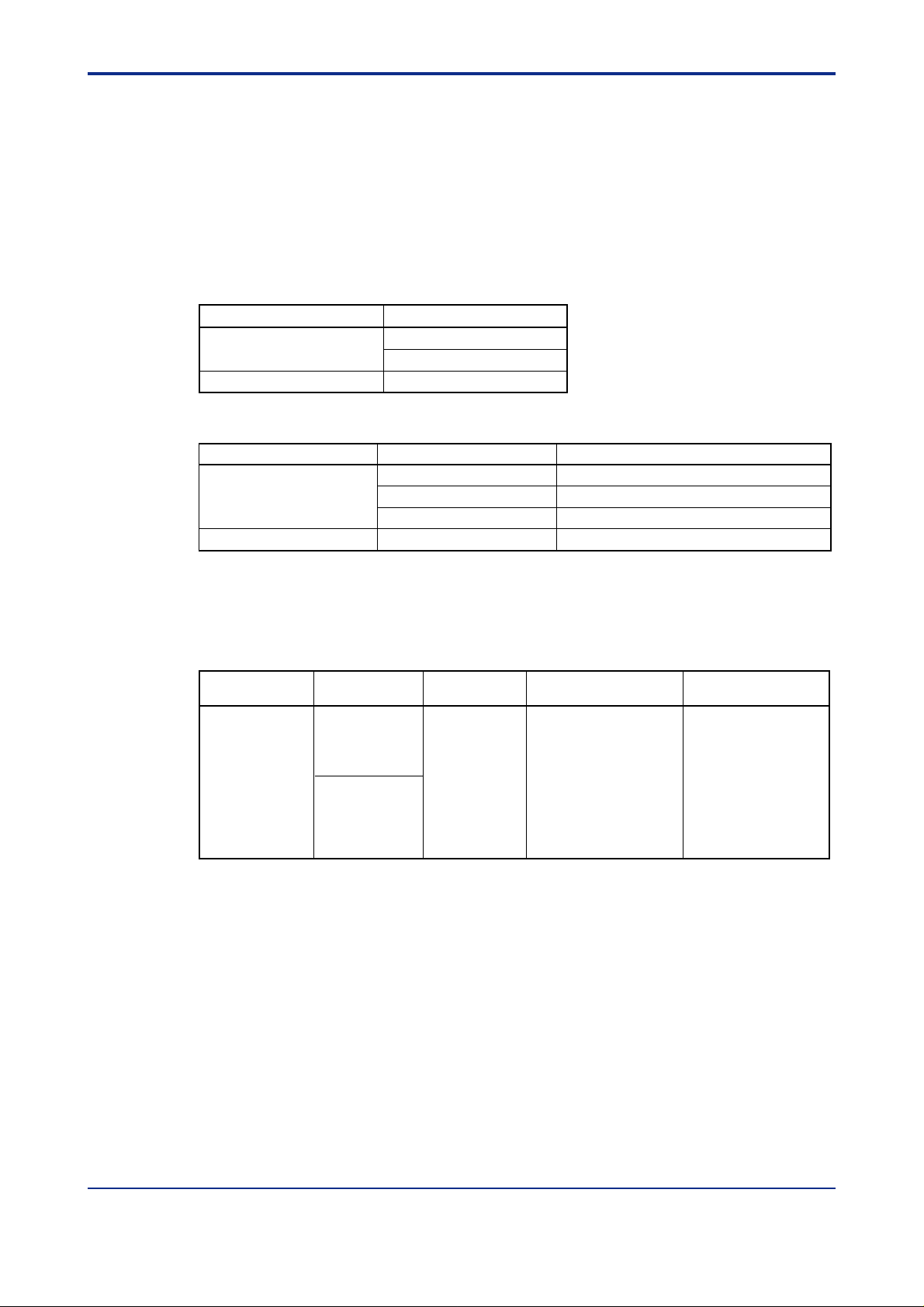
1.1 Interface Specifications
Table 1.3 RS-485 Interface
Interface Baud rate Other specifications Protocols available
Standard RS-485
Communication
system
4-wire, half-duplex
600, 1200
2400, 4800
9600bps
2-wire, half-duplex
- Asynchronous (start-stop)
- Handshaking
- Maximum communication
distance: 1200 m
- Maximum number of
connectable devices: 31
- Start bit: 1
- Data length: 8 or 7 bits
- Parity: No parity, even, odd
- Stop bit: 1 or 2
PC link communication
Ladder communication
IM 05D01D21-10E 2nd Edition: Jul. 30, 2004-00
Page 10

Blank Page
Page 11
<Toc> <2. Setup>
2. Setup
This chapter describes the procedure to set up the communication functions and
also refers to some notes on wiring and communication parameters.
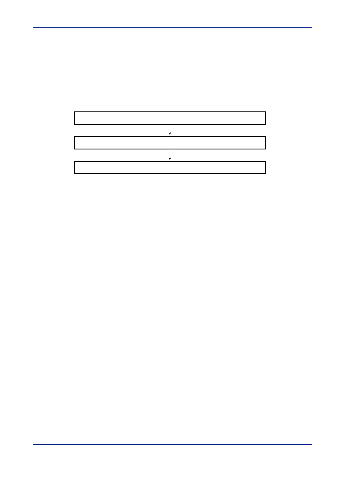
2.1 Setup Procedure
Set up the communication functions of the UT350L controller as follows:
Connect a host device and a UT350L controller. (See section 2.2.)
Set up the communication parameters of the UT350L controller. (See section 2.3.)
Create communication programs for the host device to perform communication.
Create communication programs referring to the documentation of each host device.
*
In this manual, “host devices” generically denotes PCs, PLCs (sequencers), and graphic panels.
*
2-1
IM 05E01B02-41E 2nd Edition: Jul. 30, 2004-00
Page 12
<T oc> <2. Setup>
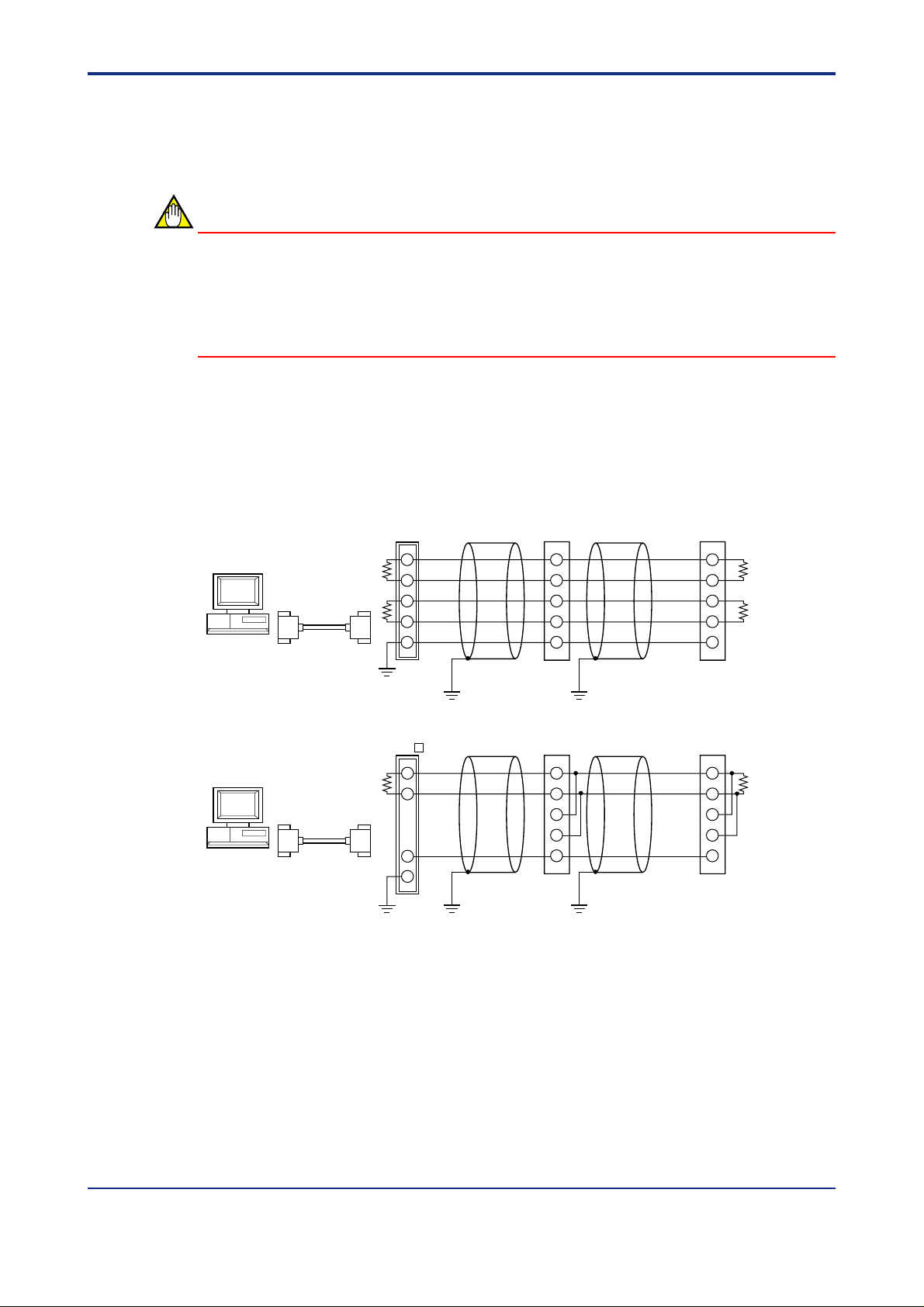
2.2 Wiring for Communication
Connect the UT350L controller and the host device for communication. The wiring procedures and precautionary notes are as follows.
NOTE
• T o avoid an electrical shock, be sure to turn off the power supply source to the equipment involved before you start wiring.
• Use crimp terminals at cable ends.
• Before you start wiring, read the user’s manual of each device.
2.2.1 Wiring to a Personal Computer
Since general personal computers cannot directly be connected to the RS-485 interface,
wiring must be provided via an RS-232C/RS-485 converter. The following figures show the
wiring for 4-wire connection and 2-wire connection.
2-2
● 4-wire connection
PC
RS-232C
straight cable
● 2-wire connection
PC
RS-232C
straight cable
Terminating resistor
220Ω1/4W
JIS Class 3 grounding
(grounding resistance
of 100Ω or less)
Terminating resistor
220Ω1/4W
JIS Class 3 grounding
(grounding resistance
of 100Ω or less)
Z-101HE UT350L UT350L
TD(+)
TD(-)
RD(+)
RD(-)
SHIELD
Communication cable
JIS Class 3 grounding
(grounding resistance
of 100Ω or less)
ML1- UT350L UT350L
B(+)
5
A(-)
3
SG
4
6
Communication cable
JIS Class 3 grounding
(grounding resistance
of 100Ω or less)
23
24
25
26
27
Communication cable
JIS Class 3 grounding
(grounding resistance
of 100Ω or less)
23
24
25
26
27
Communication cable
JIS Class 3 grounding
(grounding resistance
of 100Ω or less)
SDB(+)
SDA(-)
RDB(+)
RDA(-)
SG
SDB(+)
SDA(-)
RDB(+)
RDA(-)
SG
23
24
25
26
27
23
24
25
26
27
Terminating resistor
220Ω1/4W
Terminating resistor
220Ω1/4W
Note: Z-101HE and ML1-■ are the converters of Sharp Corporation and Y okogawa
Electric Corporation, respectively . You can also use other RS-232C/RS-485 converters.
Before you use another converter, check its electrical specifications.
IM 05D01D21-10E 2nd Edition: Jul. 30, 2004-00
Page 13
<Toc> <2. Setup>
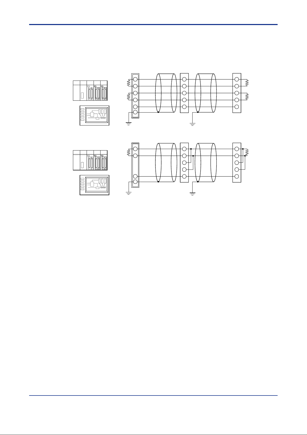
2.2.2 Wiring to a PLC (Sequencer) or Graphic Panel
Since general PLCs (sequencers) and graphic panels have an RS-485 interface, they can
be directly connected to a UT350L controller. If your PLC (sequencer) or graphic panel has
an RS-232C interface, see subsection 2.2.1.
2-3
● 4-wire connection
● 2-wire connection
PLC or graphic panel UT350L UT350L
RDB(+)
Terminating
resistor
220Ω1/4W
JIS Class 3 grounding (grounding
resistance of 100Ω or less)
PLC or graphic panel UT350L UT350L
Terminating
resistor
220Ω1/4W
JIS Class 3 grounding (grounding
resistance of 100Ω or less)
RDA(-)
SDB(+)
SDA(-)
SG
Communication cable
B(+)
A(-)
SG
Communication cable
23
24
25
26
27
Communication cable
JIS Class 3 grounding (grounding
resistance of 100Ω or less)
23
24
25
26
27
Communication cable
JIS Class 3 grounding (grounding
resistance of 100Ω or less)
SDB(+)
SDA(-)
RDB(+)
RDA(-)
SG
SDB(+)
SDA(-)
RDB(+)
RDA(-)
SG
23
24
Terminating resistor
25
26
27
23
24
25
26
27
220Ω1/4W
Terminating resistor
220Ω1/4W
IM 05D01D21-10E 2nd Edition: Jul. 30, 2004-00
Page 14
<T oc> <2. Setup>
2.3 Notes on Setting Communication Parameters
This section describes the parameters that set up the communication functions and their
setting ranges.
NOTE
The communication specifications of both the UT350L controller and the host device must
be the same. Check the communication specifications of the host device first, then set up
the communication parameters of the UT350L controller .
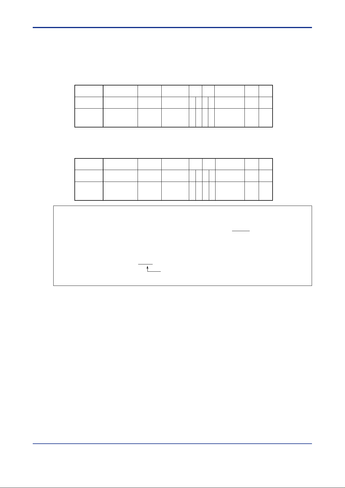
2.3.1 Procedure to Set Communication Parameters
For the operation procedure, see the User’s Manual of UT350L controller .
The UT350L are shipped from the factory with the following communication specifications.
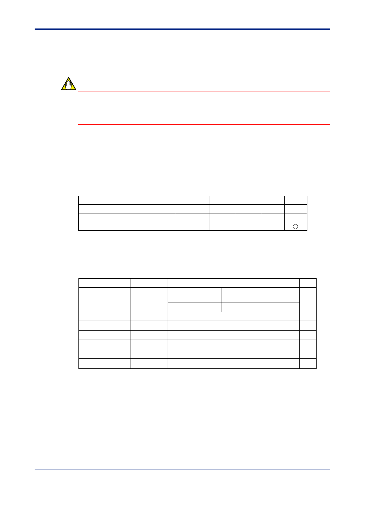
Table 2.3.1 Protocol-by-Protocol Default Parameter Settings
2-4
Communication protocol PSL BPS
PC link communication (without sum check)
PC link communication (with sum check)
Ladder communication
Note: Circled numbers denote fixed values (i.e., the parameters can neither be shown nor changed).
0
1
2
9600
9600
9600
PRI
EVEN
EVEN
EVEN
2.3.2 Description of Communication Parameters
Table 2.3.2 Communication Parameters of UT350L controller
Parameter name
Protocol selection
Address
Baud rate
Parity
Stop bit
Data length
Minimum response time
*1: Data length is fixed at 8 bits for ladder communication is selected.
Parameter code
PSL
ADR
BPS
PRI
STP
DLN
RP.T
PC link communication
Ladder communication
600, 1200, 2400, 4800, 9600 (bps)
NONE (no parity), EVEN, ODD
Setting range
0: Without sum check
1: With sum check
2: Ladder communication
1 to 99
1, 2 (bit)
1
*
7, 8 (bit)
0 to 10 (×10 ms)
STP
1
1
1
DLN
8
8
8
Default
0
1
9600
EVEN
1
8
0
1) Protocol selection (PSL)
Set the same communication protocol as that of the host device to be connected to. The
UT350L controller supports PC link and ladder communication protocols, which are specific
to UT350L controller .
2) Baud rate (BPS)
Set the same baud rate as that of the host device to be connected. (Otherwise, proper
communication cannot be achieved.) The unit of baud rate is bps (bits per second).
IM 05D01D21-10E 2nd Edition: Jul. 30, 2004-00
Page 15
<Toc> <2. Setup>
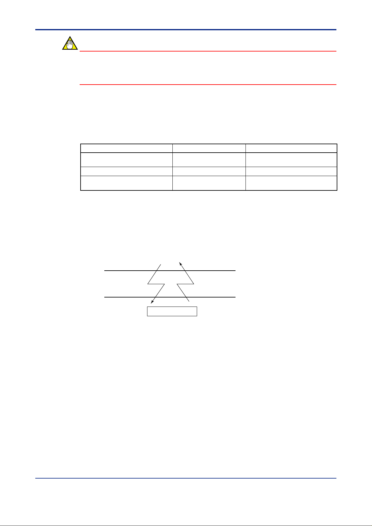
3) Address number (ADR)
Set the address number of the UT350L controller to one that is not being used by another
controller. An address number of 1 to 99 can be assigned in any order. Note that the number of UT350L controllers that can be connected to a single communication port is limited
to 31.
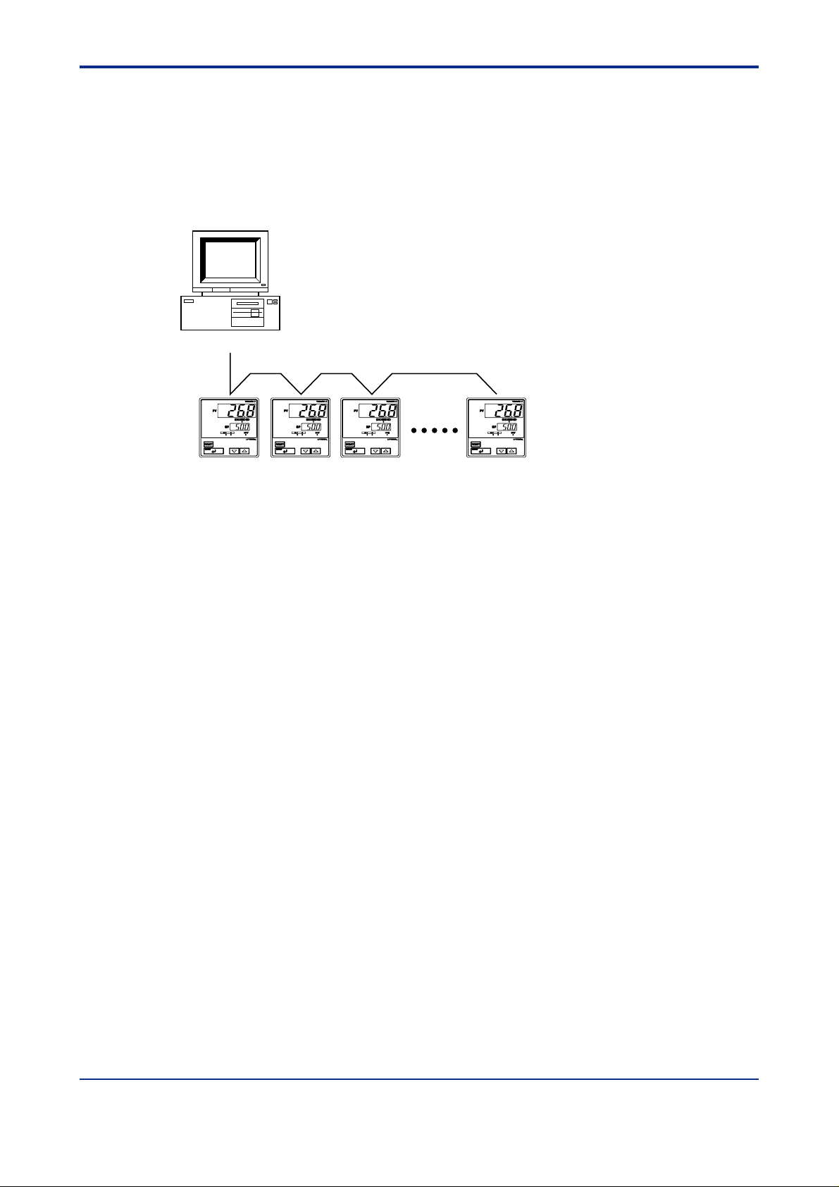
Example of connecting four UT350L controllers to a host device with address numbers of 1,
50, 10, and 20:
PC
Max. 1200 m; the maximum number of slave units: 31
2-5
ADR=1 ADR=50 ADR=10 ADR=20
4) Parity (P ARI)
Set the handling of parity to be carried out when data is sent or received. Set the same
parity state as that of the host device to be connected.
5) Stop bit (STP)
Set the same stop bit as that of the host device to be connected.
6) Data length (DLN)
Set the same data length as that of the host device to be connected. (When ladder communication is selected, the data length is fixed.)
7) Minimum response time (RP.T)
Set the time taken to respond to the host device after the UT350L controller receives
transmission data from it. The unit is 10 ms. The response time will be “communication
processing time + the set value of RP.T X 10” milliseconds.
IM 05D01D21-10E 2nd Edition: Jul. 30, 2004-00
Page 16

Blank Page
Page 17
<Toc> <3. PC Link Communication>
3. PC Link Communication
3.1 Overview
PC link communication protocol is one of the protocols used to communicate with devices
such as PCs, PLCs (sequencers), and graphic panels. Via this communication protocol,
these devices can exchange data with a UT350L controller by reading/writing the
controller’s internal registers (D registers and I relays).
Hereafter, PCs, PLCs (sequencers), and graphic panels shall be referred to as “host
devices.”
In PC link communication, a host device identifies UT350L controller with a communication
address, which ranges from 1 to 99. However, broadcasting, which requires no address
number, is possible with some of the commands. For more information, see subsection
3.2.2.
3-1
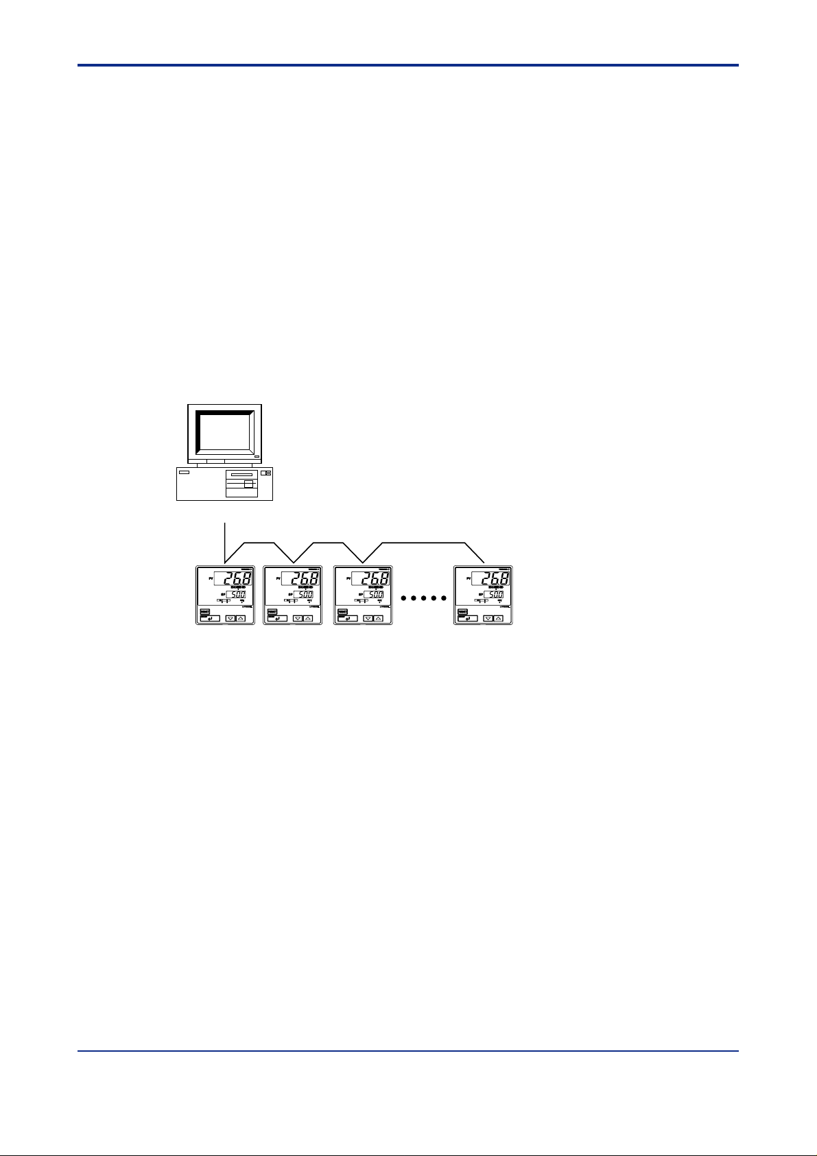
PC
Max. 1200 m; the maximum number of slave units: 31
UT350L controllers
Figure 3.1 Connection of PC Link Communication
The next section will discuss the configuration of commands and responses.
IM 05D01D21-10E 2nd Edition: Jul. 30, 2004-00
Page 18

<T oc> <3. PC Link Communication>
3.1.1 Configuration of Commands
Commands sent from a host device to a UT350L controller consist of the following elements.
3-2
Number of bytes
Element
1
STX
(1) (8) (9)(2) (3) (4) (5) (6) (7)
2
Address number
(ADR)
2
CPU number
01
1
Time to wait
for response
0
3
Command
Variable length
Data corresponding
to command
Checksum
2
1
ETX1CR
(1) STX (Start of Text)
This control code indicates the start of a command. The character code is CHR$(2).
(2) Address Number (01 to 99)
Address numbers are used by a host device to identify which UT350L controller to communicate with. (ID number of the UT350L)
Adress Number = UT350L parameter (ADR) value
(3) CPU Number
This number is fixed to 01.
(4) Time to W ait for Response
This is fixed to 0.
(5) Command (See subsection 3.2.1.)
Specify a command to be issued from the host device.
(6) Data Corresponding to Command
Specify an internal register (D register or I relay), number of data items, UT350L parameter
values, or others.
(7) Checksum
In PC link communication with sum check, the ASCII codes of the text between STX and
the checksum are converted into hexadecimal values and added on a byte basis. Then the
lowermost byte of the added results is turned into ASCII code, and its lower byte is used as
the checksum.
This 2-byte space is unnecessary for PC link communication without sum check.
(8) ETX (End of Text)
This control code indicates the end of a command string. The character code is CHR$(3).
(9) CR (Carriage Return)
This control code marks the end of a command. The character code is CHR$(13).
IM 05D01D21-10E 2nd Edition: Jul. 30, 2004-00
Page 19
<Toc> <3. PC Link Communication>
NOTE
The control codes STX, ETX, and CR in commands are indispensable. Do not miss any of
them when you create a communication program for PC link communication. A communication failure will result if any of them are omitted or if the order is incorrect.
● Data Forms of Commands
The table below shows the data forms of D registers and I relays.
Table 3.1 Data Forms
Data type Data content Data form
PV high and low limits, target setpoints,
and others
Bias, deviation alarms, and others
Limit control types, alarm types, and others
* Parameter list of UT350L controller User’s Manual for information about data form.
Measuring range (EU) data
Measuring range span (EUS) data
Seconds, absolute values, and data
without unit*
Numeric data excluding the decimal
point
Numeric data excluding the decimal point
Absolute value excluding the decimal point
3-3
● Command Format for Communication
Example: When setting a target setpoint “50.0” to a UT350L controller , the host device
sends the value “500” as command data without the decimal point (this is true for both
settings 5.00 or 500).
Data to be sent from the host device: 500
Command data: 500
UT350L side
Target setpoint: 50.0
* The position of the decimal point for “500” is determined by the DP (decimal point position) parameter
of the UT350L controller.
Response data from
UT350L: 500
IM 05D01D21-10E 2nd Edition: Jul. 30, 2004-00
Page 20

<T oc> <3. PC Link Communication>
3.1.2 Configuration of Response
Responses from a UT350L controller with respect to a command sent from the host device
consist of the elements shown below, which dif fer depending on the condition of communication - normal or failure.
1) With Normal Communication
When communication is carried out normally , the UT350L controller returns the character
string “OK” and, in response to read commands, also returns read-out data.
3-4
Number of bytes
Element1STX
Address number (ADR)2CPU number:012OK
2
Variable length
Parameter data
2
Checksum
2) In the Event of Failure
If communication is carried out abnormally , the UT350L controller returns the character
string “ER” and error codes (EC1 and EC2). (See subsection 3.2.4, Response Error
Codes.)
• No response is made in case of an error in address number specification or CPU
number specification.
• If a UT350L controller cannot receive an ETX contained in a command, a response may
not be made.
* As a measure against these situations, provide a timeout processing in the communica-
tion functions or communication programs of the host device.
Number of bytes
Element
1
STX
2
Address number
(ADR)
2
CPU number:
01
2ER2
EC12EC23Command2Checksum
1
ETX1CR
1
ETX1CR
IM 05D01D21-10E 2nd Edition: Jul. 30, 2004-00
Page 21

<Toc> <3. PC Link Communication>
3.2 Communication with Host Device
In PC link communication, when specifying D registers or I relays (internal registers of
UT350L controller), you can use the numbers as is. The numbers of these internal registers
are in the following format:
• D registers: D**** (****: numeric value)
• I relays : I**** (****: numeric value)
Host devices to be connected to a UT350L controller are those capable of handling the PC
link communication protocol.
(1) Connectable graphic panels
Graphic panels that can be connected to a UT350L controller are listed below . However, it
may be possible to connect graphic panels other than the ones listed below .
Table 3.2 List of Graphic Panels Connectable
Product Name Name Remarks
Pro-face by
Digital Electronics
Corporation
Note: For more information about Digital’s graphic panels, contact Digital Electronics Corporation.
(Be careful because the display device differs depending on the model.)
GP70 series
GP-J series
GP-230 series
GP-430 series
GP-530 series
Graphic control panel
High-speed graphic control panel
Medium-size graphic control panel
Advanced, high-speed graphic control panels
3-5
(Note)
(2) Communication with F A-M3 with UT-link module
No ladder communication program is required to communicate with FA-M3 with UT-link
module (Y okogawa PLC). The UT -link module’s function offers 2 modes, in which users can
exchange data without paying attention to the communication procedure. (For more information, see the user’s manual of UT-link module “IM 34M6H25-01E.”)
● User-specifiable mode: Always reads/writes the user-specified devices* of the
UT350L controller .
● Command mode: Accesses the devices* of the UT350L controller only when necessary.
*:“Device” here denotes the internal registers of the UT350L controller (D registers and I relays).
IM 05D01D21-10E 2nd Edition: Jul. 30, 2004-00
Page 22

<T oc> <3. PC Link Communication>
3.2.1 List of Commands
The following are the lists of commands available in PC link communication. The details of
them are explained in the description of each command.
(1) Bit-basis Access Commands Dedicated to I Relays
Command Description Number of bits handled
BRD
BWR
BRR
BRW
BRS
BRM
(2) Word-basis Access Commands
Command Description Number of words handled
WRD
WWR
WRR
WRW
WRS
WRM
Bit-basis read
Bit-basis write
Bit-basis, random read
Bit-basis, random write
Specifies I relays to be monitored on a bit-by-bit basis.
Bit-basis monitoring
Word-basis read
Word-basis write
Word-basis, random read
Word-basis, random write
Specifies internal registers to be monitored on a word-by-word basis.
Word-basis monitoring
1 to 256 bits
1 to 256 bits
1 to 32 bits
1 to 32 bits
1 to 32 bits
—
1 to 64 words
1 to 64 words
1 to 32 words
1 to 32 words
1 to 32 words
—
3-6
(3) Information Commands
Command Description Number of controllers handled
INF Reads model, version, and revision 1
IM 05D01D21-10E 2nd Edition: Jul. 30, 2004-00
Page 23

<Toc> <3. PC Link Communication>
3.2.2 Specifying Broadcast
Broadcast addressing allows the corresponding multiple UT350L controller to receive the
command.
(1)In the command, specify the broadcast address in Table 3.3 and execute it.
(2)Broadcast addressing works independently of the communication address of the
controller.
(3)Broadcast addressing is only applicable to write commands.
(4)No response is returned when broadcast addressing is used.
Broadcast data.
* No response from slaves
Higher-level device (master)
Max.: 1200 m; the maximum number of slaves: 31
3-7
Figure 3.2 Broadcasting
Table 3.3 Address Numbers
Address No. Corresponding devices
BA
01 to 99
All models of GREEN Series
Device with a corresponding address number
IM 05D01D21-10E 2nd Edition: Jul. 30, 2004-00
Page 24

<T oc> <3. PC Link Communication>
3.2.3 Commands
BRD Reads I relays on a bit-by-bit basis.
● Function
Reads the ON/OFF statuses of a sequence of contiguous I relays by the specified number
of bits, starting at a specified I relay number.
• The number of bits to be read at a time is 1 to 256.
• For the format of response in the event of failure, see subsection 3.1.2.
• The command shown below includes the checksum function. When performing
communication without checksum, do not include the 2-byte checksum element in the
command.
● Command/Response (for normal operation)
3-8
Number of
Bytes
Command
element
Number of
Bytes
Response
element
1
STX2Address
number
(ADR)
1
STX2Address
number
(ADR)
2
CPU
number
01
2
CPU
number
01
3
1
BRD
0
2OK1d11d21
5
I relay
number
1
Comma
or space
…
d3
…
3
Number
of bits
1
dn
Checksum1ETX1CR
(n)
2
Checksum1ETX1CR
2
The response is “0” when the status is OFF or “1” when ON.
dn: read data of the specified number of bits (n = 1 to 256)
dn = 0 (OFF)
dn = 1 (ON)
● Example:
Reading the status of alarm 1 of the UT350L controller with address number 01
The following command reads the status of alarm 1 (I0097) at address number 01.
[Command] STX$+ “01010BRDI0097, 001A0” +ETX$+CR$
The following response is returned with respect to the above command. (Alarm 1 is ON.)
[Response] STX$+ “0101OK18D” +ETX$+CR$
Alarm has been ON since 1 was returned.
IM 05D01D21-10E 2nd Edition: Jul. 30, 2004-00
Page 25

<Toc> <3. PC Link Communication>
BWR Writes data into I relays on a bit-by-bit basis.
● Function
Writes ON/OFF data into a sequence of contiguous I relays by the specified number of bits,
starting at a specified I relay number.
• The number of bits to be written at a time is 1 to 256.
• For the format of response in the event of failure, see subsection 3.1.2.
• The command shown below includes a checksum function. When performing commu-
nication without checksum, do not include the 2-byte checksum element in the command.
● Command/Response (for normal operation)
3-9
Number of
Bytes
Command
element
Command (continued)
…
…
1
STX2Address
number
(ADR)
1
dn
2
Checksum1ETX1CR
2
CPU
number
01
3
1
BWR
0
5
I relay
number
Write information is “0” to set OFF or “1” to set ON.
dn: write data of the specified number of bits (n = 1 to 256)
dn = 0 (OFF)
dn = 1 (ON)
Number of
Bytes
Response
element
● Example:
1
STX2Address
number
(ADR)
2
CPU
number
01
2
OK
2
Checksum1ETX1CR
Setting the user-defined flag of the UT350L controller with address number 01 to ON.
1
Comma
or space
3
Number
of bits
(n)
1
Comma
or space
1d11
d2
The following command writes ON into the user-defined flag (I0865) at address number 01.
[Command] STX$+ “01010BWRI0865, 001, 113” +ETX$+CR$
Note: The user-defined flags (I relays) are flags that the user can freely read/write. For user’s read/write-accessible areas,
see subsection 3.4.2.
“OK” is returned in response to the command above.
[Response] STX$+ “0101OK5C” +ETX$+CR$
IM 05D01D21-10E 2nd Edition: Jul. 30, 2004-00
Page 26

<T oc> <3. PC Link Communication>
BRR Reads I relays on a bit-by-bit basis in a random order .
● Function
Reads the ON/OFF statuses of the individual I relays specified in a random order by the
specified number of bits.
• The number of bits to be read at a time is 1 to 32.
• For the format of response in the event of failure, see subsection 3.1.2.
• The command shown below includes a checksum function. When performing commu-
nication without the checksum, do not include the 2-byte checksum element in the
command.
● Command/Response (for normal operation)
3-10
Number of
Bytes
Command
element
Command (continued)
…
…
Number of
Bytes
Response
element
1
STX2Address
number
(ADR)
5
I relay
number
n
1
STX2Address
number
(ADR)
2
Checksum
2
CPU
number
01
1
ETX1CR
2
CPU
number
01
3
1
BRR
0
2OK1d11
Number
of bits
d2
2
(n)
…
…
The response is “0” when the status is OFF or “1” when ON.
dn: read data of the specified number of bits (n = 1 to 32)
dn = 0 (OFF)
dn = 1 (ON)
● Example:
Reading the statuses of alarms 1 and 2 of the UT350L with address number 05
5
I relay
number
1
1
dn
1
Comma
or space
2
Checksum
5
I relay
number
2
1
ETX1CR
1
Comma
or space
The following command reads the statuses of alarm 1 (I0097) and alarm 2 (I0098) at
address number 05.
[Command] STX$+ “05010BRR02I0097, I00989D” +ETX$+CR$
In response to the command above, the ON and OFF responses are returned for alarms 1
and 2.
[Response] STX$+ “0501OK10C1” +ETX$+CR$
Alarm 1 is ON, and alarm 2 is OFF.
IM 05D01D21-10E 2nd Edition: Jul. 30, 2004-00
Page 27

<Toc> <3. PC Link Communication>
3-11
BRW
Writes data into I relays on a bit-by-bit basis in a random order.
● Function
Writes ON/OFF statuses in the individual I relays specified in a random order by the specified number of bits.
• The number of bits to be written at a time is 1 to 32.
• For the format of response in the event of failure, see subsection 3.1.2.
• The command shown below includes the checksum function. When performing
communication without the checksum, do not include the 2-byte checksum element in
the command.
● Command/Response (for normal operation)
Number of
Bytes
Command
element
Command (continued)
1
1
1
STX
2
Address
number
(ADR)
15
CPU
number
01
…
2
1
0
3
BRW
1
2
Number
of bits
(n)
1
5
I relay
number
1
2
1
Comma
or space
1
1
1
Comma
d1
or space
5
I relay
number
2
Comm
a or
space
Comma
d2
or space
…
I relay
number
n
Comma
or space
dn
Checksum
ETX1CR
Write information is “0” to set OFF or “1” to set ON.
dn: write data of the specified number of bits (n = 1 to 32)
dn = 0 (OFF)
dn = 1 (ON)
Number of
Bytes
Response
element
1
STX
2
Address
number
(ADR)
2
CPU
number
01
2
OK
2
Checksum
1
ETX1CR
● Example: Setting four user-defined flags of the UT350L controller with address number
05 to ON, OFF, OFF , and ON.
The following command sets the four user-defined flags (
I0721, I0722, I0723 , and I0724) at
address number 05 to ON, OFF, OFF , and ON, respectively.
[Command] STX$+ “05010BRW04I0721, 1, I0722, 0, I0723, 0, I0724, 18D” +ETX$+CR$
Note: The user-defined flags (I relays) are flags that the user can freely read/write. For user’s read/write-accessible areas,
see subsection 3.4.2.
“OK” is returned in response to the command above.
[Response] STX$+ “0501OK60” +ETX$+CR$
IM 05D01D21-10E 2nd Edition: Jul. 30, 2004-00
Page 28

<T oc> <3. PC Link Communication>
3-12
BRS
Specifies I relays to be monitored on a bit-by-bit basis.
● Function
Specifies the numbers of I relays to be monitored on a bit-by-bit basis. Note that this command simply specifies I relays. Actual monitoring is performed by the BRM command after
the I relay numbers are specified with this command.
When the volume of data is large and you wish to increase the communication rate, it is
effective to use a combination of the BRS and BRM commands rather than the BRD
command. If the power supply is turned off, the specified I relay numbers will be erased.
• The number of registers to be specified at a time is 1 to 32.
• For the format of response in the event of failure, see subsection 3.1.2.
• The command shown below includes the checksum function. When performing
communication without the checksum, do not include the 2-byte checksum element in
the command.
● Command/Response (for normal operation)
Number of
Bytes
Command
element
1
STX2Address
number
(ADR)
2
CPU
number
01
3
1
BRS
0
2
Number
of bits
(n)
5
I relay
number
1
1
Comma
or space
5
I relay
number
2
1
Comma
or space
Command (continued)
…
…
Number of
Bytes
Response
element
5
I relay
number
n
1
STX2Address
2
Checksum
number
(ADR)
1
ETX1CR
2
CPU
number
01
2
OK
2
Checksum
1
ETX1CR
● Example: Monitoring the stop status of the UT350L controller with address number 05
The following command monitors the stop status (
I0067) at address number 05.
(This command is used simply for specifying registers.)
[Command] STX$+ “05010BRS01I006754” +ETX$+CR$
“OK” is returned in response to the command above.
[Response] STX$+ “0501OK60” +ETX$+CR$
IM 05D01D21-10E 2nd Edition: Jul. 30, 2004-00
Page 29

<Toc> <3. PC Link Communication>
BRM Monitors I relays on a bit-by-bit basis.
● Function
Reads the ON/OFF statuses of the I relays that have been specified in advance by the
BRS command.
• Before executing this command, the BRS command must always be executed to
specify which I relays are to be monitored. If no relay has been specified, error code
06 is returned. This error also occurs if the power supply is turned off.
• For the format of response in the event of failure, see subsection 3.1.2.
• The command shown below includes the checksum function. When performing
communication without the checksum, do not include the 2-byte checksum element in
the command.
● Command/Response (for normal operation)
3-13
Number of
Bytes
Command
element
Number of
Bytes
Response
element
1
STX2Address
number
(ADR)
1
STX2Address
number
(ADR)
2
CPU
number
01
2
CPU
number
01
3
1
BRM
0
2OK1d11d21
Checksum
2
d3
1
ETX1CR
…
…
1
dn
2
Checksum
1
ETX1CR
The response is “0” when the status is OFF and “1” when ON.
dn: read data of the number of bits specified by the BRS command (n = 1 to 32)
dn = 0 (OFF)
dn = 1 (ON)
● Example: Monitoring the stop status of the UT350L controller with address number 05
(This command reads the statuses of the I relays specified by the BRS command.)
[Command] STX$+ “05010BRMD7” +ETX$+CR$
The ON/OFF status of the I relay is returned in response to the command above.
[Response] STX$+ “0501OK160” +ETX$+CR$
The I relay is ON.
IM 05D01D21-10E 2nd Edition: Jul. 30, 2004-00
Page 30

<T oc> <3. PC Link Communication>
WRD Reads D registers and I relays on a word-by-word basis.
● Function
Reads a sequence of contiguous register information on a word-by-word basis by the
specified number of words, starting at the specified register number.
• The number of words to be read at a time is 1 to 64.
• For the format of response in the event of failure, see subsection 3.1.2.
• The command shown below includes the checksum function. When performing
communication without the checksum, do not include the 2-byte checksum element in
the command.
● Command/Response (for normal operation)
3-14
Number of
Bytes
Command
element
Number of
Bytes
Response
element
1
STX2Address
number
(ADR)
1
STX
2
Address
number
(ADR)
2
CPU
number
01
2
CPU
number
01
OK
1
0
WRD
2
3
4
dddd14dddd2
5
Register
number
1
Comma
or space
…
…
2
Number
of words
(n)
4
ddddn
2
Checksum
2
Checksum1ETX1CR
The response is returned in a 4-digit character string (0000 to FFFF) in a hexadecimal pattern.
dddn: Read data of the specified number of words
ddddn = character string in a hexadecimal pattern
n = 1 to 64
● Example:
Reading a measured input value of the UT350L controller with address number 03
The following command reads the measured input value (D0003) at address number 03.
[Command] STX$+ “03010WRDD0003, 0175” +ETX$+CR$
The measured input value 200 (00C8 (HEX)) is returned in response to the command
above.
1
ETX1CR
[Response] STX$+ “0301OK00C839” +ETX$+CR$
IM 05D01D21-10E 2nd Edition: Jul. 30, 2004-00
Page 31

<Toc> <3. PC Link Communication>
3-15
WWR
Writes data into D registers and I relays on a word-by-word basis.
● Function
Writes information into a sequence of contiguous registers on a word-by-word basis by the
specified number of words, starting at the specified register number .
• The number of words to be written at a time is 1 to 64.
• For the format of response in the event of failure, see subsection 3.1.2.
• The command shown below includes the checksum function. When performing
communication without the checksum, do not include the 2-byte checksum element in
the command.
● Command/Response (for normal operation)
Number of
Bytes
Command
element
Command (continued)
4
1
STX2Address
…
number
(ADR)
4
CPU
number
01
1
2
2
3
0
WWR
5
Register
number
1
Comma
or space
2
Number
of words
(n)
1
Comma
or space
4
dddd1
dddd2
…
ddddn
Checksum1ETX1CR
Write information is specified in a 4-digit character string (0000 to FFFF) in a hexadecimal pattern.
dddn: Write data of the specified number of words
ddddn = character string in a hexadecimal pattern
n = 1 to 64
Number of
Bytes
Response
element
1
STX2Address
number
(ADR)
2
CPU
number
01
2
OK
2
Checksum1ETX1CR
● Example: Writing “200” into the target setpoint of the UT350L controller with address
number 03.
The following command writes data 200 (
00C8 (HEX)) into the target setpoint (D0301) at
address number 03.
[Command] STX$+ “03010WWRD0301, 01, 00C890” +ETX$+CR$
“OK” is returned in response to the command above.
[Response] STX$+ “0301OK5E” +ETX$+CR$
IM 05D01D21-10E 2nd Edition: Jul. 30, 2004-00
Page 32

<T oc> <3. PC Link Communication>
3-16
WRR
Reads D registers and I relays on a word-by-word basis in random order.
● Function
Reads the statuses of the individual registers, on a word-by-word basis, specified in a
random order by the specified number of words.
• The number of words to be read at a time is 1 to 32.
• For the format of response in the event of failure, see subsection 3.1.2.
• The command shown below includes the checksum function. When performing
communication without the checksum, do not include the 2-byte checksum element in
the command.
● Command/Response (for normal operation)
Number of
Bytes
Command
element
Command (continued)
…
1
STX2Address
5
number
(ADR)
2
2
CPU
number
01
1
3
1
0
WRR
2
Number
of words
(n)
5
Register
number
1
1
Comma
or space
5
Register
number
2
1
Comma
or space
Register
…
number
Number of
Bytes
Response
element
Checksum
(n)
1
STX2Address
number
(ADR)
ETX1CR
2
CPU
number
01
2
OK
4
dddd14dddd2
…
…
4
ddddn
2
Checksum
1
ETX1CR
The response is returned in a 4-digit character string (0000 to FFFF) in a hexadecimal pattern.
ddddn = character string in a hexadecimal pattern (n = 1 to 32)
● Example: Reading the measured input and control output values of the UT350L control-
ler with address number 10.
The following command reads the measured input value (
(
D0005) at address number 10.
D0003) and control output value
[Command] STX$+ “10010WRR02D0003, D00058B” +ETX$+CR$
The measured input value 200 (00C8 (HEX)) and output value 50 (0032 (HEX)) are returned as the
response to the above command.
[Response] STX$+ “1001OK00C80032FC” +ETX$+CR$
IM 05D01D21-10E 2nd Edition: Jul. 30, 2004-00
Page 33

<Toc> <3. PC Link Communication>
3-17
WRW
Writes data into D registers and I relays on a word-by-word basis in random order.
● Function
Writes register information specified for each register into the registers specified in a
random order by the specified number of words.
• The number of words to be written at a time is 1 to 32.
• For the format of response in the event of failure, see subsection 3.1.2.
• The command shown below includes the checksum function. When performing
communication without the checksum, do not include the 2-byte checksum element in
the command.
● Command/Response (for normal operation)
Number of
Bytes
Command
element
Command (continued)
5
1
STX2Address
1
number
(ADR)
4
2
CPU
number
01
…
1
3
0
WRW
5
Number
of words
1
(n)
2
4
5
Register
number
1
1
Comma
or space
2
4
dddd1
Comma
or space
1
Register
number
2
Comma
or space
dddd2
Register
…
number
Comma
or space
n
ddddn
Checksum1ETX1CR
Write information is specified in a 4-digit character string (0000 to FFFF) in a hexadecimal pattern.
ddddn: Repetition of register numbers and write information of the specified number of words
ddddn = character string in a hexadecimal pattern
n = 1 to 32
Number of
Bytes
Response
element
1
STX2Address
number
(ADR)
2
CPU
number
01
2
OK
2
Checksum1ETX1CR
● Example: Writing “20.0” into the target setpoint and “15.0” into the alarm-1 setpoint of
the UT350L controller with address number 10.
The following command writes
“20.0” into the target setpoint (D0301) and “15.0” into the alarm-1 setpoint (D0915) at address
number 10.
[Command] STX$+ “10010WRW02D0301, 00C8, D0915, 00969D” +ETX$+CR$
Target setpoint: 200
Alarm setpoint: 150
“OK” is returned in response to the command above.
[Response] STX$+ “1001OK5C” +ETX$+CR$
IM 05D01D21-10E 2nd Edition: Jul. 30, 2004-00
Page 34

<T oc> <3. PC Link Communication>
3-18
WRS
Specifies the D registers and I relays to be monitored on a word-by-word basis.
● Function
Specifies the numbers of the registers to be monitored on a word-by-word basis. Note that
this command simply specifies the registers. Actual monitoring is performed by the WRM
command after the register numbers are specified by this command.
If the volume of data is large and you wish to increase the communication rate, it is effective
to use a combination of the WRS and WRM commands rather than the WRD command. If
the power supply is turned off, the register numbers specified will be erased.
• The number of words to be specified at a time is 1 to 32.
• For the format of response in the event of failure, see subsection 3.1.2.
• The command shown below includes the checksum function. When performing
communication without the checksum, do not include the 2-byte checksum element in
the command.
● Command/Response (for normal operation)
Number of
Bytes
Command
element
1
STX2Address
number
(ADR)
CPU
number
01
1
2
3
0
WRS
2
Number
of words
(n)
5
Register
number
1
1
Comma
or space
5
Register
number
2
1
Comma
or space
Command (continued)
…
…
Number of
Bytes
Response
element
5
Register
number
n
1
STX2Address
2
Checksum
number
(ADR)
1
ETX1CR
2
CPU
number
01
2
OK
2
Checksum
1
ETX1CR
● Example: Monitoring the measured input value of the UT350L controller with address
number 01.
The following command monitors the measured input value (D0003) at address number 01.
(This command simply specifies the registers.)
[Command] STX$+ “01010WRS01D000356” +ETX$+CR$
CPU number: 01 D register number: D0003
“OK” is returned in response to the command above.
[Response] STX$+ “0101OK5C” +ETX$+CR$
IM 05D01D21-10E 2nd Edition: Jul. 30, 2004-00
Page 35

<Toc> <3. PC Link Communication>
3-19
WRM
Monitors the D register and I relays on a word-by-word basis.
● Function
Reads the information of the registers that have been specified in advance by the WRS
command.
• Before executing this command, the WRS command must always be executed to
specify which registers are to be monitored. If no register has been specified, error
code 06 is returned. This error also occurs if the power supply is turned off.
• For the format of response in the event of failure, see subsection 3.1.2.
• The command shown below includes the checksum function. When performing
communication without the checksum, do not include the 2-byte checksum element in
the command.
● Command/Response (for normal operation)
Number of
Bytes
Command
element
1
STX2Address
number
(ADR)
2
CPU
number
01
1
3
0
WRM
2
Checksum1ETX1CR
Number of
Bytes
Response
element
1
STX2Address
number
(ADR)
2
CPU
number
01
2
OK
4
dddd14dddd2
…
…
4
ddddn
2
Checksum1ETX1CR
The response is returned in a 4-digit character string (0000 to FFFF) in a hexadecimal pattern.
ddddn: Read data of the number of words specified by the WRS command
ddddn = character string in a hexadecimal pattern
n = 1 to 32
● Example: Monitoring the measured input value of a UT350L controller with address
number 01
The following command monitors the measured input value (D0003) at address number 01.
(This command reads the status of the register specified by the WRS command.)
[Command] STX$+ “01010WRME8” +ETX$+CR$
CPU number: 01
The measured input value 200 (00C8 (HEX)) is returned in response to the command above.
[Response] STX$+ “0101OK00C837” +ETX$+CR$
Measured input value: 200
IM 05D01D21-10E 2nd Edition: Jul. 30, 2004-00
Page 36

<T oc> <3. PC Link Communication>
■
■
INF Reads the model, version, and revision information.
● Function
Reads the model code, version number , and revision number of the UT350L controller.
• For the format of response in the event of failure, see subsection 3.1.2.
● Command/Response (for normal operation)
3-20
Number of
Bytes
Command
element
Number of
Bytes
Response
element
Response (continued)
4
(Note 5)
Note 1: Model name and options of UT350L Controller
● Model code of UT350L LC350
Note 2: Version and revision numbers
1
STX2Address
1
STX2Address
4
0000
(Note 6)
2
number
(ADR)
number
(ADR)
Checksum1ETX1CR
CPU
number
01
2
CPU
number
01
2
-0
1
Response
time:
0
2
OK
3
INF16
8
Model code:
LC350-0
(Note 1)
0: No option
1: With communication
revision numbers
2
Checksum1ETX1CR
8
Version and
(Note 3)
(Note 2)
4
0001
4
(Note 4)
V01. R00
Space (blank)
Revision number
Version number
Note 3:Valid in Non-user-specifiable mode.
* The value in this field is the first read register number, which is “0001” for all models.
Note 4:Valid in Non-user-specifiable mode.
* The value in this field is the number of registers read in Non-user-specifiable mode: “0008” for UT350L.
Note 5:Valid in Non-user-specifiable mode.
* The value in this field is the first write register number: “0001” for UT350L.
Note 6:Valid in Non-user-specifiable mode.
* The value in this field is the number of registers written in Non-user-specifiable mode, which is “0000” for all models.
*: One of the convenient modes used when communicating with FA-M3 with UT-link module. (See section 3.2.)
IM 05D01D21-10E 2nd Edition: Jul. 30, 2004-00
Page 37

<Toc> <3. PC Link Communication>
3.2.4 Response Error Codes
See Also
Subsection 3.1.2, Configuration of Response, for the structure of the response in the event
of an error.
The error codes (EC1) and detailed error codes (EC2) of response are as follows.
Table 3.4 Error Codes (EC1)
3-21
Error code Meaning
02
03
04
05
06
08
42
43
44
Command error
Internal register
specification error
Out of setting range
Number of data error
Monitor error
Parameter error
Sum error
Internal buffer overflow
Timeout between received
characters
Table 3.5 Detailed Error Codes (EC2)
Error code
(EC1)
03
04
05
08
Meaning
Internal register
specification error
Out of setting range
Number of data error
Parameter error
Causes
• The command does not exist.
• Command not executable
• Specified register number does not exist.
• In handling bit registers (I relays) on a word-by-word basis,
its specification is not correct.
• A character other than 0 and 1 was used for bit setting.
• A value other than 0000 to FFFF was specified in the word
specification.
• The start address specified for data loading/saving is out of
the address range.
• Specified number of bits or words is too large.
• The number of data or registers specified and the number
of parameters for them are inconsistent.
• An attempt was made to execute monitoring without
specifying any device to be monitored (BRS or WRS).
• Wrong parameter.
• The sum does not match.
• Too much data was received.
• No terminal character or ETX is received.
Detailed error code (EC2)
Indicates the parameter number where an error occurred
(HEX). This is the number of a parameter in sequence that
first resulted in an error when counted from the leading
parameter.
Example:
STX 01010BRW 03 I0097 , 1, I0098, 0, A00502, 0
Parameter number 1 2 3 4 5 6
In this case, EC1 = 03 and EC2 = 06
Error in internal register
specification
↓
For EC1 error codes other than those noted above, EC2 has no meaning.
IM 05D01D21-10E 2nd Edition: Jul. 30, 2004-00
Page 38

Blank Page
Page 39

<Toc> <4. Ladder Communication>
4. Ladder Communication
4.1 Overview
By using ladder communication, you can easily perform communication between a PLC
(sequencer) and a UT350L controller . This kind of communication allows for the reading/
writing of D registers (internal registers of UT350L controller).
In ladder communication, a PLC identifies each instrument by its station number, which
ranges from 1 to 99.
PLC (sequencer)
MAX 1200 m; the maximum number of slave units: 31
4-1
Figure 4.1 Connecting with Ladder Communication
IM 05D01D21-10E 2nd Edition: Jul. 30, 2004-00
Page 40

<T oc> <4. Ladder Communication>
4.1.1 Configuration of Commands
Commands sent from a PLC consist of the following elements.
4-2
Number of
Bytes
Number of
BCD digits
Element
1
2
Station number
(1) (2) (3) (4) (5) (6)
1
2
CPU
number
01
2
4
Parameter
number
1 01
11 1
1
1
0
R/W
+/–
(7) (8)
2
4
Read/write data
(1) Station Number (01 to 99)
The station number is used by the PLC to identify which instrument to communicate with.
(ID number of UT350L controller)
(2) CPU Number
This number is fixed to 01.
(3) Parameter number
For D registers, 4-digit BCD data of a D register number with its leading character “D”
removed.
(4) 0
2
CR
1
2
LF
(9)
This is fixed to 0.
(5) 0
This is fixed to 0.
(6) R/W
0: Read
1: Write
(7) +/-
0: Positive data (+)
1: Negative data (-)
(8) Read/write data
For read operation, the number of data items to be read. (64 at maximum)
For write operation, setting data with a 4-digit BCD value excluding the decimal point.
(9) CR, LF
These control codes mark the end of a command. The character codes for CR and LF are
CHR$(13) and CHR$(10), respectively .
IM 05D01D21-10E 2nd Edition: Jul. 30, 2004-00
Page 41

<Toc> <4. Ladder Communication>
● Data Forms of Commands
The table below shows the data forms of D registers.
Table 4.1 Data Forms
4-3
Data type
PV high and low limits, target setpoints, and others
Bias, deviation alarms, and others
Limit control types, alarm types, and others
* Parameter list of UT350L controller User’s Manual for information about data form.
Measuring range (EU) data
Measuring range span (EUS) data
Seconds, absolute values, and data
without unit*
Data content
Numeric data not including the decimal point
Numeric data not including the decimal point
Absolute value not including the decimal point
Data form
● Command Format for Communication
Example: When setting the target setpoint 50.00 to a UT350L controller , the PLC sends the
value 5000 as command data without the decimal point (this is also true for both settings
5.000 or 500.0).
Data to be sent from the PLC: 5000
Command data: 5000
UT350L controller side
Target setpoint: 50.00
Response data from a UT350L
controller: 5000
* The position of the decimal point for 5000 is determined by the DP (decimal point position) parameter
of the UT350L controller.
4.1.2 Configuration of Response
Response from a UT350L controller with respect to a command sent from the PLC consists
of the elements shown below.
Number of
Bytes
Number of
BCD digits
Element
1
2
Station number
1
2
CPU
number
01
Parameter
number
2
4
the length of this part varies: 64 data items at maximum.
11 1
1 01
When responding to a data read command,
1
1
0
R/W
+/–
2
4
Read/write data
CR
1
2
2
LF
IM 05D01D21-10E
2nd Edition: Jul. 30, 2004-00
Page 42

<T oc> <4. Ladder Communication>
4.2 Communication with PLC
With ladder communication you cannot specify D registers (internal registers of UT350L
controller) by using their numbers as is. Set register numbers as shown below.
• D register: 4-digit BCD value of the register number (with “D” removed)
PLCs that can communicate with UT350L controllers are those capable of using the ladder
communication protocol.
PLCs that can be connected to a UT350L controller are listed below .
Table 4.2 List of PLCs that can be connected
4-4
Supplier
Yokogawa Electric
Corporation
Mitsubishi Electric
Corporation, or others
Note: For more information about the PLCs listed above, contact the supplier.
FA500
FA-M3
MELSEC-A series and
others
PLCs that can communicate
in handshaking mode.
Product
With communication module (RZ91-ON)
With communication module (F3RZ91-ON)
With computer link unit
With computer link unit
Requirement
For details, see the instruction manual of the PCL to be connected.
Remarks
(Note)
IM 05D01D21-10E 2nd Edition: Jul. 30, 2004-00
Page 43

<Toc> <4. Ladder Communication>
4.2.1 Reading Data
Shown below are the configurations of commands and responses when data in a UT350L
controller is read by the PLC.
● Commands
4-5
Number of
bytes
Number of
BCD digits
Element
Station number
● Responses
Number of
bytes
Number of
BCD digits
Element
...
...
Station number
1
1 01
0
1
1
2
2
CR
LF
2
1
4
dddd2
2
4
1
2
CPU
number
01
2
CPU
number
01
1
2
CR
2
4
Parameter
number
2
4
Parameter
number
1
2
LF
11
0
0
1
0
(first data)
1
0
1
+/–
1 01
111
1 01
1
0
Number of data
items to read (n)
2
4
dddd1
2
4
11
1 01 01
0
+/–
Second dataData of the parameter number
1
2
1
2
1
1
1
0
+/–
ddddn
nth data
● Example:
Reading a measured input value of a UT350L controller with station number 01
The following command reads the measured input value (D0003) at station number 01.
[Command] “01010003000000010D0A”
In response to the command above, the measured input value “200” is returned.
[Response] “01010003000002000D0A”
“0200” has been returned.
IM 05D01D21-10E
2nd Edition: Jul. 30, 2004-00
Page 44
<T oc> <4. Ladder Communication>
4.2.2 Writing Data
Shown below are the configurations of commands and responses when data is written to a
UT350L controller from the PLC.
● Commands
4-6
Number of
bytes
Number of
BCD digits
Element
1
2
Station number
2
CPU
number
01
2
4
Parameter
number
111
1 01
2
1
1
1
+/–
0
4
dddd
CR
1
1
2
2
LF
● Responses
Number of
bytes
Number of
BCD digits
Element
● Example: W riting “200” to the target setpoint 1 value of a UT350L controller with
station number 01.
The following command writes “200” to the target setpoint 1 (D0301) at station number 01.
[Command] “01010301001002000D0A”
In response to the command above, the following response is returned. (Target setpoint 1 value is 200.)
1
2
Station number
2
CPU
number
01
2
4
Parameter
number
111
101
2
1
1
1
+/–
0
4
dddd
CR
1
1
2
2
LF
[Response] “01010301001002000D0A”
“0200” has been returned.
IM 05D01D21-10E 2nd Edition: Jul. 30, 2004-00
Page 45

<Toc> <4. Ladder Communication>
4.2.3 Response Error Codes
The PLC may receive the following responses in the event of error .
Table 4.4 Response in the Event of Error
Error condition Data sent from PLC Data PLC receives
A non-existing parameter number was sent.
Characters other than BCD codes were used
in an element other than a station number.
An LF code (0A) was used in an element
other than a station number.
Specified station number does not match any
of the controllers connected.
The write data was outside the range.
Wrong command length.
(Command length is 10 bytes including CR
and LF codes.)
A timeout occurred when sending data.
(Timeout: 5 seconds)
Send buffer overflowed.
(The buffer capacity is 199 bytes.)
0101 0000 0000 0001 CRLF
“0000” is the wrong parameter number.
0101 0123 0000 000B CRLF
0101 0123 000B 0000 CRLF
0101 0123 0B00 0000 CRLF
0101 012B 0000 0000 CRLF
0101 0123 0000 000A CRLF
0101 0123 000A 0000 CRLF
0101 0123 0A00 0000 CRLF
0101 010A 0000 0000 CRLF
0103 0123 0000 0000 CRLF
0001 0123 0000 0000 CRLF
3301 0123 0000 0000 CRLF
0101 0123 0011 9999 CRLF
“9999” is the data outside the range.
0101 0123 0000 00 CRLF
0101 0123 00 0000 CRLF
0101 0 0000 0000 CRLF
0101 0000 0000 FFFF CRLF
“FFFF” is returned.
0101 FFFF FFFF FFFF CRLF
No response
No response
0101 0123 0011 0050 CRLF
“0050” is the current setting of the
parameter.
No response
No response
No response
4-7
A framing error or a parity error occurred.
No response
NOTE
If you try to read data of a parameter number that is not in the D register table, or that
corresponds to a vacant cell in that table, no error occurs and 0 is returned.
IM 05D01D21-10E
2nd Edition: Jul. 30, 2004-00
Page 46

<T oc> <4. Ladder Communication>
4.3 Communication with MELSEC
By way of ladder communication, a UT350L controller can exchange data, via its internal
registers, with PLCs of suppliers other than Yokogawa. Sections 4.2 and 4.3 explain how to
implement ladder communication with a MELSEC-A Series instrument (product of
Mitsubishi Electric Corp.), which is often used in ladder communication.
Example
● System configuration:
4-8
MELSEC-A Series
Slot No.
Address No. 1 2 3
08
DI unit
Computer
link unit
RS-485 communication
UT350L controller
Computer link unit used at MELSEC-A:
Use either (1) or (2) below.
(1) A1SJ71UC24-R4
(2) A1SJ71C24-R4
IM 05D01D21-10E 2nd Edition: Jul. 30, 2004-00
Page 47

<Toc> <4. Ladder Communication>
4.3.1 Preparing for Communication
Provide wiring and set communication specifications.
4.3.2 Wiring
Connect the computer link unit of MELSEC-A to the UT350L controller’s communication
terminals.
4-9
Communication
terminals of
MELSEC-A
SDA(+)
SDB(-)
RDA(+)
RDB(-)
SG
Shield
JIS Class 3 grounding
(grounding resistance
of 100Ω or less)
The terminating resistor ratings are 220 W, 1/4W for UT350L controllers and 330 W, 1/4W
for MELSEC-A instruments. The largest terminating resistor which is 330 W , 1/4W, should
be provided.
Terminating resistor
330Ω1/4W
Communication terminals
of GREEN Series (1)
SDB(+)
SDA(-)
RDB(+)
RDA(-)
23
24
25
26
SG
27
JIS Class 3 grounding
(grounding resistance
of 100Ω or less)
Communication terminals
of GREEN Series (2)
SDB(+)
SDA(-)
RDB(+)
RDA(-)
23
24
25
26
SG
27
JIS Class 3 grounding
(grounding resistance
of 100Ω or less)
Communication terminals
of GREEN Series (3)
SDB(+)
SDA(-)
RDB(+)
RDA(-)
SG
23
24
25
26
27
Terminating resistor
330Ω1/4W
IM 05D01D21-10E
2nd Edition: Jul. 30, 2004-00
Page 48

<T oc> <4. Ladder Communication>
4.3.3 Setting Communication Specifications
After wiring is finished, set the same communication specifications at both the UT350L and
MELSEC-A ’s computer link unit.
● Communication settings of UT350L
Communication settings are made to the software. Call up the setup parameters under the
R485 menu, and set them up.
Code Parameter name Setting Remarks
PSL
BPS
PRI
STP
DLN
RP.T
Protocol selection
Communication rate
Parity
Stop bit
Data length
Minimum response time
2 (ladder communication)
1
*
4 (9600)
1 (EVEN)
1
8
0
For the operation procedure, see the User’s Manual of each UT350L controller .
Must be set to 2 to perform ladder communication.
0 : 600, 1 : 1200, 2 : 2400, 3 : 4800, 4 : 9600 (bps)
0 : NONE, 1 : EVEN, 2 : ODD
1, 2
7, 8
0 to 10 (x10 ms)
4-10
IM 05D01D21-10E 2nd Edition: Jul. 30, 2004-00
Page 49

<Toc> <4. Ladder Communication>
● Transmission settings of MELSEC-A
Set the switches of the computer link unit as shown below in steps (1) to (3).
MELSEC-A
sequencer
(1) Mode switch
4
MODE
Computer link
module
3
1
Communication
2
setting switches
Set to “4.”
Mode 4 sets the following.
Communication rate: 9600 bps
Parity: even
Stop bit: 1
Data length: 1
(1) Mode switch
(2) Transmission spec. switches
(3) Station number switches
MODE Description
0 to 3
4
:
:
8
9 to E
F
Disabled
Handshaking mode
Format-4 protocol mode
Disabled
MELSEC test mode
4-11
(2) Transmission specification switches ( : Not used for communication with a UT350L controller.)
01 04 05 12
is ON.
Multi-link
Disabled
19200
OFF
ON
ON
7 bits
No
Odd
1 bit
No
Disabled
ON
ON
ON
Switch
No.
01
02
03
04
05
06
07
08
09
10
11
12
0N.
Item
Not used.
Link selection
Not used.
Write in RUN mode
Communication rate (bps)
300
OFF
OFF
OFF
Data bit length
Parity bit
Parity bit type
Stop bit selection
Sum check
600
ON
OFF
OFF
2400
OFF
ON
OFF
Setting
ON OFF
Computer link
Enabled
4800
OFF
OFF
ON
8 bits
Yes
Even
2 bits
Yes
9800
ON
OFF
ON
(3) Station number switches
0
x10: Sets the 10th digit.
0
x1: Sets the 1st digit.
x10: Set to “0.”
x1: Set to “0.”
IM 05D01D21-10E
2nd Edition: Jul. 30, 2004-00
Page 50

Blank Page
Page 51

<Toc> <5. Functions and Use of D Registers>
5. Functions and Use of D Registers
5.1 Overview
This section explains the functions and use of D registers.
D registers store parameter data, flag data and process data of the UT350L controller. Y ou
can readily use these internal data items by reading from or writing to the D registers.
Y ou can use D registers to perform:
● Centralized control using a host device
● Data exchange by reading/writing data from/to a host device
5.2 Interpretation of D Register T ables
This section explains how to read the D Register Map tables in this chapter . The numbers
listed in the leftmost column are D register numbers ((1) below). Each register code name
in the D Register Map tables represents a specific process data item, operating parameter,
setup parameter or other data items such as a flag. For details on the operating parameters
and setup parameters, see the user’s manual of UT350L.
5-1
D-Reg No.
D0001
(1) D register number
Name of D Register Map
Register name
ADERROR
R/W
R
Permission of read/write by communication
An asterisk (*) in this column indicates that the
number of writing actions is limited to 100,000.
IM 05D01D21-10E 2nd Edition: Jul. 30, 2004-00
Page 52

<T oc> <5. Functions and Use of D Registers>
5.3 Classification of D Registers
■ Classification of D Register Map T ables
The table below outlines how the D registers are classified by their numbers in the D
Register Map tables.
Table 5.1 Classification of D Registers
Register No. Area and data categories Description Reference
D0001 to D0049
D0050 to D0100
Process data area (Note 1)
User area (Note 2),
represented by shaded cells
in the table
Data displayed for operation
_
PV, SP, and others
If a graphic panel is used, this area is
used for communication with the
graphic panel.
5-2
Section 5.4
Section 5.4
D0101 to D0230
D0231 to D0256
D0257 to D0900
D0901 to D0903
D0904 to D1253
Note 1: Data for process values, operating parameters and setup parameters are stored in the types (EU, EUS, %, or ABS without the decimal
point) indicated in the Operating Parameter Lists and Setup Parameter Lists of the user’s manual of UT350L. The OFF and ON states are
represented by 0 and 1, respectively. D registers D0001 to D0049 are read-only.
Note 2: When communicating with a graphic panel, do not write to or read from this area (D0050 to D0100) because this area is reserved for 16-
bit register data used by graphic panels.
[See Also] Section 5.4, Process Data and User Area.
Cannot be used.
Operating parameters
(Note 1)
Setup parameters (Note 1)
SP and Alarm setpoint parameters
Cannot be used.
Cannot be used.
PV input, alarm type, retransmission
output, and communication parameters
SP, A1, A2, BS, FL, H
IN, AL, HY, PSL, etc.
Section 5.5
Section 5.6
Section 5.7
Section 5.8
NOTE
It is prohibited to read/write data by communication from/to the registers of blank cells in the
register map tables. If you attempt to do so, the UT350L may not operate properly.
IM 05D01D21-10E 2nd Edition: Jul. 30, 2004-00
Page 53

<Toc> <5. Functions and Use of D Registers>
5.4 Process Data and User Area
Area for process data
D-Reg No. Register name R/W
D0001 ADERROR R D0051 R/W
D0002 ERROR R D0052 R/W
D0003 PV R D0053 R/W
D0004 CSP R D0054 R/W
D0005 R D0055 R/W
D0006 R D0056 R/W
D0007 R D0057 R/W
D0008 MOD R D0058 R/W
D0009 TIME R D0059 R/W
D0010 MAX/MIN R D0060 R/W
D0011 ALM R D0061 R/W
D0012 D0062 R/W
D0013 D0063 R/W
D0014 D0064 R/W
D0015 D0065 R/W
D0016 D0066 R/W
D0017 D0067 R/W
D0018 D0068 R/W
D0019 D0069 R/W
D0020 D0070 R/W
D0021 D0071 R/W
D0022 D0072 R/W
D0023 D0073 R/W
D0024 D0074 R/W
D0025 D0075 R/W
D0026 D0076 R/W
D0027 D0077 R/W
D0028 D0078 R/W
D0029 D0079 R/W
D0030 D0080 R/W
D0031 D0081 R/W
D0032 D0082 R/W
D0033 D0083 R/W
D0034 D0084 R/W
D0035 PARAERR R D0085 R/W
D0036 D0086 R/W
D0037 D0087 R/W
D0038 D0088 R/W
D0039 D0089 R/W
D0040 D0090 R/W
D0041 D0091 R/W
D0042 D0092 R/W
D0043 D0093 R/W
D0044 D0094 R/W
D0045 D0095 R/W
D0046 D0096 R/W
D0047 D0097 R/W
D0048 D0098 R/W
D0049 D0099 R/W
D0050 R/W D0100 R/W
Shaded area : User area (You cannot use these registers when a graphic panel is used.)
D-Reg No. Register name R/W
5-3
IM 05D01D21-10E 2nd Edition: Jul. 30, 2004-00
Page 54

<T oc> <5. Functions and Use of D Registers>
5.4.1 Process Data Area (Read-only)
Some of the registers in this area (D0001 to D0049, read-only) are designed to represent
two or more events, such as errors and statuses, using combinations of bits within the
register. If any of the events shown in the following tables occur, the corresponding bit is set
to 1. The bit remains 0 if the event does not occur . Note that bits with blank fields in the
tables are not in use.
● Bit Configuration of D0001: ADERROR (Input Error)
Bit Code Event
0 ADERR Input A/D converter error
1 to 15
● Bit Configuration of D0002: ERROR (PV Error)
Bit Code Event
0
1 PVBO PV burnout error
2 RJCERR PV RJC error
3
4 PV+over PV over-scale
5 PV-over PV under-scale
6 to 15
5-4
● D0003: PV (Measured input value)
● D0004: CSP (Current target setpoint [SP])
● Bit Configuration of D0008: MOD (Operation mode)
Bit Code Event
0
1 EXD 1:EXCEED
2 OUT Output Relay; 1:on, 0:off
3 to 15
● Bit Configuration of D0011: ALM (Alarm Status)
Bit Code Event
0 ALM1 ‘1’ when alarm 1 is ON; ‘0’ when OFF
1 ALM2 ‘1’ when alarm 2 is ON; ‘0’ when OFF
2 to 15
[See Also]User’s Manual of UT350L
IM 05D01D21-10E 2nd Edition: Jul. 30, 2004-00
Page 55

<Toc> <5. Functions and Use of D Registers>
● Bit Configuration of D0035: P ARAERR (Error in calibration values and
parameters)
Bit Code Event
0 CALB.E Calibration value error
1 to 5
6 SETUP Setup parameter error
7
8 PARA.E Operation parameter error
9 to 11
12 EEP.E EEPROM error
13
14 SYSTEM.E System data error
15
5.4.2 User Area
Register No. Category Description
D0050 to D0100 User area
Users can read/write data from/to the registers in this area.
However, if a graphic panel is used in the system, users cannot use this area because it
is reserved for communication with the graphic panel.
5-5
IM 05D01D21-10E 2nd Edition: Jul. 30, 2004-00
Page 56

<T oc> <5. Functions and Use of D Registers>
5.5 Alarm Setpoint, Bias, and Filter Parameters
Area for Alarm Setpoint, Bias, and Filter Parameters
D-Reg No. Register name R/W
D0201 D0251
D0202 D0252
D0203 D0253
D0204 D0254
D0205 D0255
D0206 D0256 H *R/W
D0207 D0257
D0208 D0258
D0209 D0259
D0210 D0260
D0211 D0261
D0212 D0262
D0213 D0263
D0214 D0264
D0215 D0265
D0216 D0266
D0217 D0267
D0218 D0268
D0219 D0269
D0220 D0270
D0221 D0271
D0222 D0272
D0223 D0273
D0224 D0274
D0225 D0275
D0226 D0276
D0227 D0277
D0228 D0278
D0229 D0279
D0230 D0280
D0231 A1 *R/W D0281
D0232 A2 *R/W D0282
D0233 D0283
D0234 D0284
D0235 D0285
D0236 D0286
D0237 D0287
D0238 D0288
D0239 D0289
D0240 D0290
D0241 D0291
D0242 D0292
D0243 BS *R/W D0293
D0244 FL *R/W D0294
D0245 D0295
D0246 D0296
D0247 D0297
D0248 D0298
D0249 D0299
D0250 D0300
D-Reg No. Register name R/W
5-6
An asterisk (*) indicates that the number of writing actions is limited to 100,000.
IM 05D01D21-10E 2nd Edition: Jul. 30, 2004-00
Page 57

<Toc> <5. Functions and Use of D Registers>
5.5.1 Data Area for Alarm Setpoint, Bias, and Filter Parameters
Register No. Category Description Remarks
D0231 to D0232
D0243 to D0244
Alarm setpoint parameters
Computation parameters
A1 to A2: Alarm setpoints for alarm 1 to 2
BS: PV bias
FL: PV filter
For details on the
parameters, see the User’s
Manual of UT350L
5-7
IM 05D01D21-10E 2nd Edition: Jul. 30, 2004-00
Page 58

<T oc> <5. Functions and Use of D Registers>
5.6 SP Parameter
Area for SP Parameter
D-Reg No. Register name R/W
D0301 SP *R/W D0351
D0302 D0352
D0303 D0353
D0304 D0354
D0305 D0355
D0306 D0356
D0307 D0357
D0308 D0358
D0309 D0359
D0310 D0360
D0311 D0361
D0312 D0362
D0313 D0363
D0314 D0364
D0315 D0365
D0316 D0366
D0317 D0367
D0318 D0368
D0319 D0369
D0320 D0370
D0321 D0371
D0322 D0372
D0323 D0373
D0324 D0374
D0325 D0375
D0326 D0376
D0327 D0377
D0328 D0378
D0329 D0379
D0330 D0380
D0331 D0381
D0332 D0382
D0333 D0383
D0334 D0384
D0335 D0385
D0336 D0386
D0337 D0387
D0338 D0388
D0339 D0389
D0340 D0390
D0341 D0391
D0342 D0392
D0343 D0393
D0344 D0394
D0345 D0395
D0346 D0396
D0347 D0397
D0348 D0398
D0349 D0399
D0350 D0400
D-Reg No. Register name R/W
5-8
An asterisk (*) indicates that the number of writing actions is limited to 100,000.
IM 05D01D21-10E 2nd Edition: Jul. 30, 2004-00
Page 59

<Toc> <5. Functions and Use of D Registers>
5.6.1 Data Area for SP Parameter
Register No. Category Description Remarks
D0301 Operating parameters
SP: Target setpoint
5-9
IM 05D01D21-10E 2nd Edition: Jul. 30, 2004-00
Page 60

<T oc> <5. Functions and Use of D Registers>
5.7 Alarm T ype, Limit Control Type Selection, and Retransmission Parameters
Area for Alarm Type and Limit Control Type Selection Parameters
D-Reg No. Register name R/W
D0901 D0951
D0902 D0952
D0903 D0953
D0904 TMU *R/W D0954
D0905 D0955
D0906 D0956
D0907 D0957
D0908 D0958
D0909 D0959
D0910 D0960
D0911 D0961
D0912 D0962
D0913 D0963
D0914 D0964
D0915 AL1 *R/W D0965
D0916 AL2 *R/W D0966
D0917 D0967
D0918 D0968
D0919 HY1 *R/W D0969
D0920 HY2 *R/W D0970
D0921 D0971
D0922 D0972
D0923 D0973
D0924 D0974
D0925 D0975
D0926 D0976
D0927 D0977
D0928 D0978
D0929 D0979
D0930 R.MD *R/W D0980
D0931 D0981
D0932 DIS *R/W D0982
D0933 HI.LO *R/W D0983
D0934 OP.SL *R/W D0984
D0935 D0985
D0936 D0986
D0937 D0987
D0938 D0988
D0939 D0989
D0940 D0990
D0941 D0991
D0942 D0992
D0943 D0993
D0944 D0994
D0945 D0995
D0946 D0996
D0947 D0997
D0948 D0998
D0949 D0999
D0950 D1000
D-Reg No. Register name R/W
5-10
An asterisk (*) indicates that the number of writing actions is limited to 100,000.
IM 05D01D21-10E 2nd Edition: Jul. 30, 2004-00
Page 61

<Toc> <5. Functions and Use of D Registers>
Area for Retransmission Parameters
D-Reg No. Register name R/W
D1001 D1051
D1002 D1052
D1003 D1053
D1004 D1054
D1005 D1055
D1006 D1056
D1007 D1057
D1008 D1058
D1009 D1059
D1010 D1060
D1011 D1061
D1012 D1062
D1013 RET *R/W D1063
D1014 RTH *R/W D1064
D1015 RTL *R/W D1065
D1016 D1066
D1017 D1067
D1018 D1068
D1019 D1069
D1020 D1070
D1021 D1071
D1022 D1072
D1023 D1073
D1024 D1074
D1025 D1075
D1026 D1076
D1027 D1077
D1028 D1078
D1029 D1079
D1030 D1080
D1031 D1081
D1032 D1082
D1033 D1083
D1034 D1084
D1035 D1085
D1036 LOCK *R/W D1086
D1037 D1087
D1038 D1088
D1039 D1089
D1040 D1090
D1041 D1091
D1042 D1092
D1043 D1093
D1044 D1094
D1045 D1095
D1046 D1096
D1047 D1097
D1048 D1098
D1049 D1099
D1050 D1100
D-Reg No. Register name R/W
5-11
An asterisk (*) indicates that the number of writing actions is limited to 100,000.
IM 05D01D21-10E 2nd Edition: Jul. 30, 2004-00
Page 62

<T oc> <5. Functions and Use of D Registers>
5.7.1 Data Area for Alarm Type, Hysteresis, Limit Control T ype Selection Parameters
Register No. Category Description Remarks
D0904
D0915 to D0916
Time unit for duration time
Alarm setting parameters
TMU
AL1 to AL2
For alarm types, see the User’s Manual of UT350L.
5-12
D0919 to D0920
D0930
D0932
D0933
D0934
Alarm hysteresis
Restart mode
The way of confirmation
Limit control type selection
Operating display selection
HY1 to HY2
R.MD
DIS
HI.LO
OP.SL
0.0 to 100.0% of measured input range span
For details on the parameters, see the User’s Manual
of UT350L.
5.7.2 Data Area for Retransmission and Key-lock Parameters
Register No. Category Description Remarks
D1013 to D1015
D1036
Retransmission output setting
parameters
Key-lock setting parameters
RET to RTL
LOCK
For details on the parameters, see the User’s Manual
of UT350L.
IM 05D01D21-10E 2nd Edition: Jul. 30, 2004-00
Page 63

<Toc> <5. Functions and Use of D Registers>
5.8 PV Input, Control Output, and Communication Parameters
Area for PV Input and Communication Parameters
D-Reg No. Register name R/W
D1201 IN *R/W D1251 DLN R
D1202 UNI *R/W D1252 ADR R
D1203 D1253 RP.T R
D1204 RH *R/W D1254
D1205 RL *R/W D1255
D1206 SDP *R/W D1256
D1207 SH *R/W D1257
D1208 SL *R/W D1258
D1209 BSL *R/W D1259
D1210 RJC *R/W D1260
D1211 D1261
D1212 D1262
D1213 D1263
D1214 D1264
D1215 D1265
D1216 D1266
D1217 D1267
D1218 D1268
D1219 D1269
D1220 D1270
D1221 D1271
D1222 D1272
D1223 D1273
D1224 D1274
D1225 D1275
D1226 D1276
D1227 D1277
D1228 D1278
D1229 D1279
D1230 D1280
D1231 D1281
D1232 D1282
D1233 D1283
D1234 D1284
D1235 D1285
D1236 D1286
D1237 D1287
D1238 D1288
D1239 D1289
D1240 D1290
D1241 D1291
D1242 D1292
D1243 D1293
D1244 D1294
D1245 D1295
D1246 D1296
D1247 PSL R D1297
D1248 BPS R D1298
D1249 PRI R D1299
D1250 STP R D1300
D-Reg No. Register name R/W
5-13
An asterisk (*) indicates that the number of writing actions is limited to 100,000.
IM 05D01D21-10E 2nd Edition: Jul. 30, 2004-00
Page 64

<T oc> <5. Functions and Use of D Registers>
5.8.1 Data Area for PV Input, and Communication Parameters
Register No. Category Description Remarks
D1201 to D1210
D1247 to D1253
PV input parameters
RS-485 communication
parameters
IN to RJC
PSL to RP.T
For details on the parameters, see the User’s
Manual of UT350L.
5-14
IM 05D01D21-10E 2nd Edition: Jul. 30, 2004-00
Page 65

<Toc> <6. Functions and Use of I Relays>
6. Functions and Use of I Relays
6.1 Overview
This chapter explains the functions and use of I relays.
I relays contain status information of errors, operation, and alarms. Contents of I relays can
be read only by means of communication using a host device. (Note that the I relays have
the same information as the D registers but with I relays some of the information is readonly.)
Y ou can use I relays to perform:
● Centralized monitoring through a display created with a host device.
6.2 Status I Relays
The configuration of status I relay area is as shown below .
Table 6.1 Classification of I Relays
6-1
I relay No. Category Description Remarks
1 to 16
17 to 32
33 to 48
49 to 64
65
66 and 67
68 to 96
99 to 720
721 to 784
Status
Do not use.
User-definable area
Input error (same as D0001)
PV error (same as D0002)
Do not use.
Error in calibration values or parameters (same as D0035)
Do not use.
EXCEEDED flag and OUT lamp flag
Alarm flag
NOTE
• When specifying an I relay number for communication, begin the number with the
character “I.” For example, set I0019 to specify the RJCERR relay (I relay No.: 0019).
• In the area for I relays 1 to 720, it is prohibited to write data to I relays with blank cells
in I relay map tables. If you attempt to do so, the UT350L may not operate properly.
IM 05D01D21-10E 2nd Edition: Jul. 30, 2004-00
Page 66

<T oc> <6. Functions and Use of I Relays>
Status Area
No. I relay name
1 ADERROR 33 65 97 ALM1 129 161
23466EXD 98 ALM2 130 162
33567OUT 99 131 163
4 36 68 100 132 164
5 37 69 101 133 165
6 38 70 102 134 166
7 39 71 103 135 167
8 40 72 104 136 168
9 41 73 105 137 169
10 42 74 106 138 170
11 43 75 107 139 171
12 44 76 108 140 172
13 45 77 109 141 173
14 46 78 110 142 174
15 47 79 111 143 175
16 48 80 112 144 176
17 49 CALB.E 81 113 145 177
18 PVBO 50 82 114 146 178
19 RJCERR 51 83 115 147 179
20 52 84 116 148 180
21 PV+over 53 85 117 149 181
22 PV-over 54 86 118 150 182
23 55 SETUP 87 119 151 183
24 56 88 120 152 184
25 57 PARA.E 89 121 153 185
26 58 90 122 154 186
27 59 91 123 155 187
28 60 92 124 156 188
29 61 EEP.E 93 125 157 189
30 62 94 126 158 190
31 63 SYSTEM.E 95 127 159 191
32 64 96 128 160 192
No. I relay name No. I relay name No. I relay name No. I relay name No. I relay name
6-2
6.3 User Area
I relay No. Category Description
721 to 784 User area
You can read/write data from/to the area for I relays 721 to 784 via
communication. That is, you can use the area freely without affecting the control
function of UT350L.
IM 05D01D21-10E 2nd Edition: Jul. 30, 2004-00
Page 67

<Int> <Toc>
Revision Information
● Title : Model UT350L Limit Controller Communication Funcitons User’s Manual
● Manual No. : IM 05D01D21-10E
May 2001/1st Edition
Newly published
Jul 2004/2nd Edition
Change of the company name
i
Written by Yokogawa Electric Corporation
Published by Yokogawa Electric Corporation
2-9-32 Nakacho, Musashino-shi, Tokyo 180-8750, JAPAN
IM 05E01B02-41E 2nd Edition: Jul. 30, 2004-00
Page 68

Blank Page
Page 69

Page 70

YOKOGAWA ELECTRIC CORPORATION
Network Solutions Business Division
2-9-32, Nakacho, Musashino-shi, Tokyo, 180-8750 JAPAN
Phone: +81-422-52-7179 Facsimile: +81-422-52-6793
Sales Branch Offices
Tokyo, Nagoya, Osaka, Hiroshima, Fukuoka
YOKOGAWA CORPORATION OF AMERICA
Headquaters
2 Dart Road, Newnan, GA. 30265-1094 U.S.A.
Phone: +1-770-253-7000 Facsimile: +1-770-251-0928
Sales Branch Offices / Texas, Chicago, Detroit, San Jose
YOKOGAWA EUROPE B. V.
Headquaters
Databankweg 20, 3821 AL Amersfoort THE NETHERLANDS
Phone: +31-334-64-1611 Facsimile: +31-334-64-1610
Sales Branch Offices / Houten (The Netherlands), Wien (Austria), Zaventem
(Belgium), Ratingen (Germany), Madrid (Spain), Bratislava (Slovakia), Runcorn (United
Kingdom), Milano (Italy), Velizy villacoublay(France), Johannesburg(Republic of South
Africa)
YOKOGAWA AMERICA DO SUL S.A.
Headquarters & Plant
Praca Acapulco, 31-Santo Amaro, Sao Paulo/SP, BRAZIL CEP-04675-190
Phone: +55-11-5681-2400 Facsimile: +55-11-5681-4434
YOKOGAWA ENGINEERING ASIA PTE. LTD.
Head office
5 Bedok South Road, Singapore 469270 SINGAPORE
Phone: +65-6241-9933 Facsimile: +65-6241-2606
YOKOGAWA ELECTRIC KOREA CO., LTD.
Seoul Sales office
395-70, Shindaebang-dong, Dongjak-gu, Seoul,156-010, KOREA
Phone: +82-2-3284-3000 Facsimile: +82-2-3284-3019
YOKOGAWA TAIWAN CORPORATION
Head office
17F, No.39, Sec. 1, Chung Hwa Road Taipei, 100 TAIWAN
Phone: +886-2-2314-9166 Facsimile: +886-2-2314-9918
YOKOGAWA AUSTRALIA PTY. LTD.
Head office
Centrecourt D1, 25-27 Paul Street North, North Ryde, N. S. W. 2113, AUSTRALIA
Phone: +61-2-9805-0699 Facsimile: +61-2-9888-1844
YOKOGAWA INDIA LTD.
Head office
40/4 Lavelle Road, Bangalore, 560 001, INDIA
Phone: +91-80-227-1513 Facsimile: +91-80-227-4270
LTD. YOKOGAWA ELECTRIC
Grokholskiy per. 13, Build. 2, 4th Floor, 129010, Moscow, RUSSIA FEDERATION
Phone: +7-095-737-7868 Facsimile: +7-095-737-7869
 Loading...