

Page 1
<<Contents>> <<Index>>
General
Specifications
Model UT350L
Limit Controller
GS 05D01D21-01E
■Overview
The UT350L is an FM approved limit controller that can be
configured either as a high limit or as a low limit controller
by a user.
The UT350L features universal input, two alarm outputs,
retransmission output, a timer to count the total time the
setpoint is exceeded, and a register to retain the maximum
temperature reached.
The RS485 communication interface is available optionally.
■Features
• The large LED display of measured value whose character
is 20mm in height allows the good readability.
• Universal input is provided. The input type can be set and
changed easily by software.
• Retransmission function is included in the standard
features.
UT350L
SP
12
12
■Function Specifications
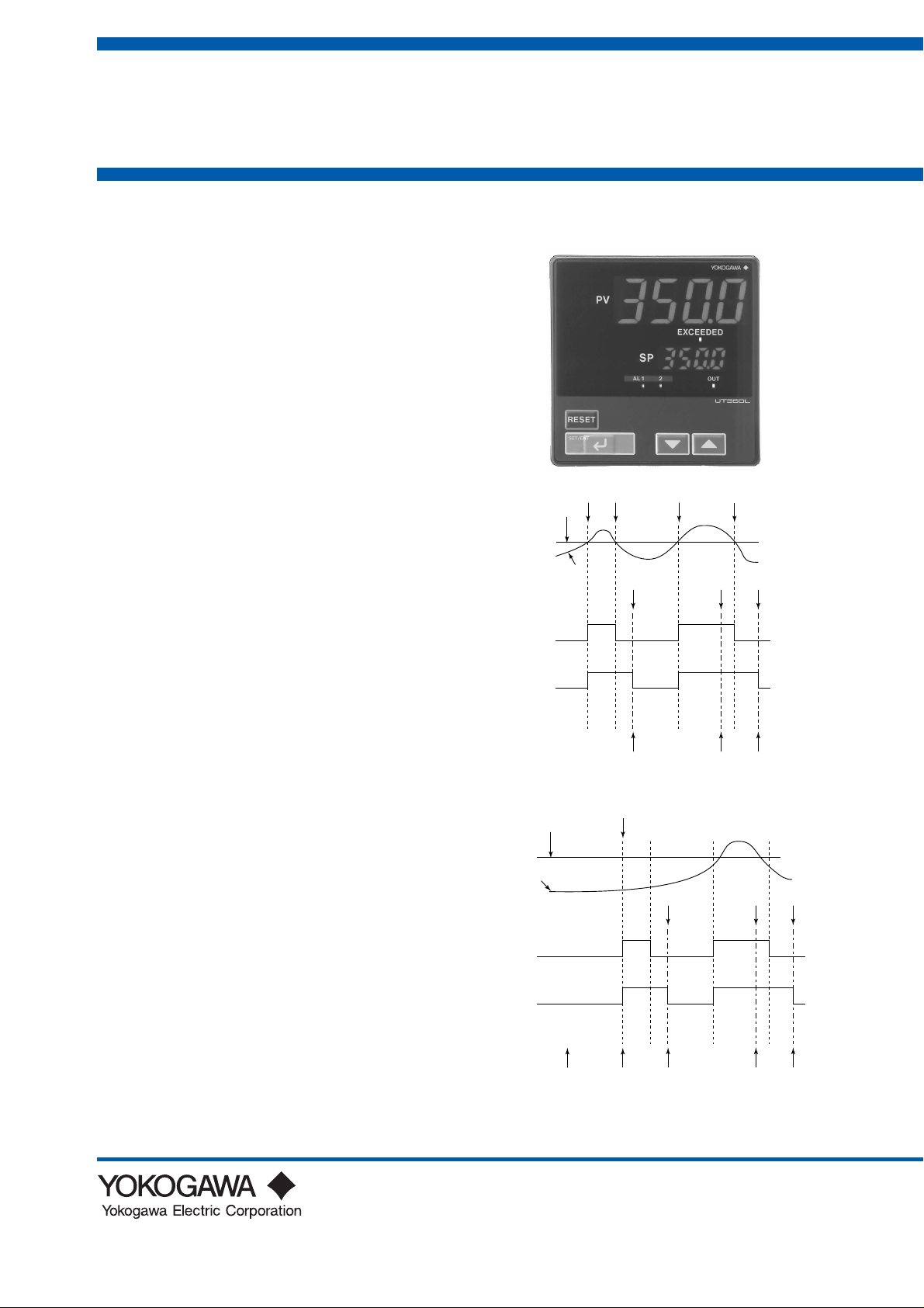
Limit Control Function
Setpoint : 1
Control type : high limit or low limit
Limit action : latching
When measured value (PV) exceeds the setpoint(SP), both
the “Exceeded” lamp and “OUT” lamp turn on.(1)
“Exceeded” lamp turns off when PV goes into normal
status, however, “OUT” lamp remains lit.(2)
“OUT” lamp turns off when the confirmation is done with
pressing the “RESEST” key by the operator.(3)
The confirmation(RESET) is not allowed while PV
exceeds SP.(4)
■State of Output Relay
State of output relay is de-energized whenever OUT lamp
is lit. When PV has not exceeded SP since power-on, state
of output relay is de-energized. (NC terminal : CLOSE,
NO terminal : OPEN) and after confirmation is done, the
state of output relay is energized. (NC terminal : OPEN,
NO terminal : CLOSE)
It is also possible to make the relay energized immediately
after power-on by the software setting.
At power-off, the relay is de-energized (NC terminal :
CLOSE, NO terminal : OPEN).
Control parameter setting range:
ON/OFF hysteresis band : 0.0 to 100.0 of instrument range
width.
Resrart mode:
Relay status at power-on can be selected.
EXCEEDED
Lamp
OUT
Lamp
PV
EXCEEDED
Lamp
OUT
Lamp
PV
SP
power off
power on
&
not over temp
(Settable as off, either)
3
(not accepted)
1
243
confir-
mation
43
confirmation
confirmation
(not accepted)
confirmationconfirmation
lit
off
lit
off
confir-
mation
lit
off
lit
off
GS 05D01D21-01E
© Copyright Apr. 1996 (YK)
4th Edition Apr. 2007 (KP)
Page 2

<<Contents>> <<Index>>
2
● Signal Computation Function
Measured input computation:
Bias addition (-100.0 to 100.0 % of measured input
range width), and first-order lag filter (time constant off
or 1 to 120 s)
Contact input function:
Limit output confirmation
● Alarm Function
Types of alarm functions are provided. The alarm status is
indicated by the alarm lamp on the front panel. Also, two
points among them can be output as relay contact outputs.
Alarm types:
PV high limit, PV low limit, Deviation high limit,
Deviation low limit, De-energized on deviation high
limit, De-energized on deviation low limit, Deviation
high and low limits, Deviation within high and low
limits, De-energized on PV high limit,
De-energized on PV low limit.
Alarm output: 2 points.
Setting ranges for PV alarm and deviation alarm:
PV alarm: -100.0 to 100.0% of measured input range
Deviation alarm: -100.0 to 100.0% of measured input
range span
Alarm hysteresis width: 0.0 to 100.0% of measured
input range span
Waiting action:
Waiting action can be set to make PV/deviation alarm
stand-by during start-up until PV reaches the normal
region.
Fault diagnostic alarm:
Input burnout, A/D conversion error, thermocouple
reference junction compensation error.
FAIL output:
Software failure and/or hardware failure.
When in fail, retransmission output and alarm output
become 0% or OFF.
● Display and Operation Function
PV display:
In 4-digit digital display of engineering unit
Setpoint display:
Various data, such as the setpoint (SP), are displayed
by selection on the 4-digit digital display.
Status indicating lamps:
2 alarm indicator lamps: AL1, AL2
Exceeded lamp: Lit when PV exceeds SP
Output status lamp: Lit when output relay is de-
energized.
Operation keys:
▲ and ▼ keys: Increase or decrease setpoints and
various parameters.
SET/ENT key: For data setting or call-up/selection of
various parameters.
RESET key: Confirms the limit status and resets the
output.
Security function:
An operation-inhibiting mode using a password is
provided.
■Communication Specifications (op-
tional)
This controller has a communication function and can be
connected to a personal computer, programmable
controllers or other GREEN Series controllers.
Communication protocol:
Computer link communication: Communication protocol
with a personal computer.
Ladder communication: Communication protocol with
programmable controller.
Communication interface:
Communication protocol: Computer link or ladder
communication
Standards: EIA RS485
Maximum number of connectable controllers: 31
GREEN Series controllers
Maximum communication distance: 1,200 m
Communication method: Two-wire half duplex or four-
wire half duplex, start-stop synchronization,
non-procedural.
Communication rate: 600, 1200, 2400, 4800, 9600 bps
■Hardware Specifications
● PV Input Signal
Number of input points : 1
Input system:
The types of input/measurement ranges can be set
using software from a list of inputs.
Types of inputs, measurement ranges and measurement
accuracy: Refer to the table on page 4.
Burnout detection:
Functions with a thermocouple (TC), RTD, standard
signal 0.4 to 2 V, and 1 to 5 V.
Can be specified as upscale, downscale, and off. For
standard signal, judged as burnout at 0.1 V or less.
Input bias current : 0.05 µA (for TC/RTD)
Input resistance:
1 MΩ or more for TC/mV
About 1 MΩ for DC voltage input
Allowable signal source resistance:
250 Ω or less; effect of permissible signal source
resistance 0.1 µV/Ω or less for TC/mV
2 k Ω or less; effect of permissible signal source
resistance 0.01%/100 Ω or less for DC
voltage
Allowable leadwire resistance:
Max. of 150 Ω/wire (resistance in each of three wires
must be equal) for RTD.
However, 10 Ω/wire in the range of -150.0 to 150.0°C.
Effect of permissibe leadwire resistance:
0.1°C/10 Ω or less
Allowable input voltage:
± 10 V DC for TC/mV/RTD
± 20 V DC for DC voltage
Noise rejection ratio:
Normal mode 40 dB (50/60 Hz) or more
Common mode 120 dB (50/60 Hz) or more
Reference-junction compensation error:
± 1.0°C (15 to 35°C), ± 1.5°C (0 to 15°C, 35 to 50°C)
Applicable standards : JIS, IEC, or DIN for TC and RTD
Response time: 2 second or less, 63% (10 - 90%)
(The time required for transmission output to reach
63% of the maximum excursion when PV abruptly
changes from 10% to 90%)
All Rights Reserved. Copyright © 1996, Yokogawa Electric Corporation
GS 05D01D21-01E 4th Edition Apr. 02, 2007-00
Page 3
<<Contents>> <<Index>>
3
Retransmission Output
Either PV or target setpoint is output.
Number of output points: 1
Output signal: 4 to 20 mA DC
Load resistance: 600 Ω or less
Output accuracy: ± 0.3% of span
Control Output
The control output is a relay output.
Number of output points : 1
Output signal: Three terminals for NC, NO, and
Common transfer-contacts
Contact rating: 250 V AC, 3 A or 30 V DC, 3A (resistive
load)
Resolution: 10 ms
Contact Input
Usage: Confirmation of limit output
Number of input points: 1
Input type: Voltage-free contact input or transistor contact
input
Input contact rating: 12 V DC, 10 mA or more
On/off determination:
For contact input,
ON = contact resistance of 1 kΩ or less,
OFF = contact resistance of 20 kΩ or more.
For transistor contact input,
ON = 2 V or less,
OFF = leakage current of 100 µA or less.
Minimum retention time for status detection: 1 s
Contact Output
Usage: Alarm output and FAIL output
Number of relay contact output points: 2
Relay contact rating: 240 V AC, 1 A or 30 V DC, 1 A
● Display Specifications
PV display: 4-digit, 7-segment red LED; character height -
20 mm
Setpoint display: 4-digit, 7-segment red LED; character
height - 9.3 mm
Status indicating lamps : LEDs
● Conformance to Safety and EMC Standards
Safety: Complies with IEC/EN61010-1 (CE), approved by
C22.2 No.61010-1, approved by UL508.
Certified for FM-3810 and FM-3545.
Installation category : CAT. II
Pollution degree : 2 (IEC/EN61010-1, C22.2
No.61010-1)
Measurement category : I (CAT. I : IEC/
EN61010-1)
Rated measurement input voltage : 10V DC
max.(across terminals), 300V AC max.(across
ground)
Rated transient overvoltage : 1500V (Note)
Note : It is a value on the safety standard
which is assumed by IEC/EN61010-1 in
Measurement category I, and is not the value
which guarantees an apparatus performance.
EMC standards:Complies with EN61326, EN61000-3-2,
EN61000-3-3 and EN55011 (CE).
Class A Group 1.
During test, the controller continues to operate
with the measurement accuracy within ±20%
of the range.
● Construction, Mounting, and Wiring
Construction: Front panel drip-proof (IP55 compatible)
Material: ABS resin and polycarbonate
Case color: Black
Weight: Approx. 1 kg or less
External dimensions: 96 (width) x 96 (height) x 100
Mounting: Direct panel mounting; mounting bracket, one
Panel cutout dimensions:
Mounting attitude: Up to 30 degrees above the horizontal.
Wiring: M3.5 (ISO 3.5 mm) screw terminals (signal wiring
(depth) mm
each for upper and lower mounting
92
+0.8
(width) x
0
92
+0.8
0
mm
No downward tilting allowed.
and power/ground wiring as well)
(height)
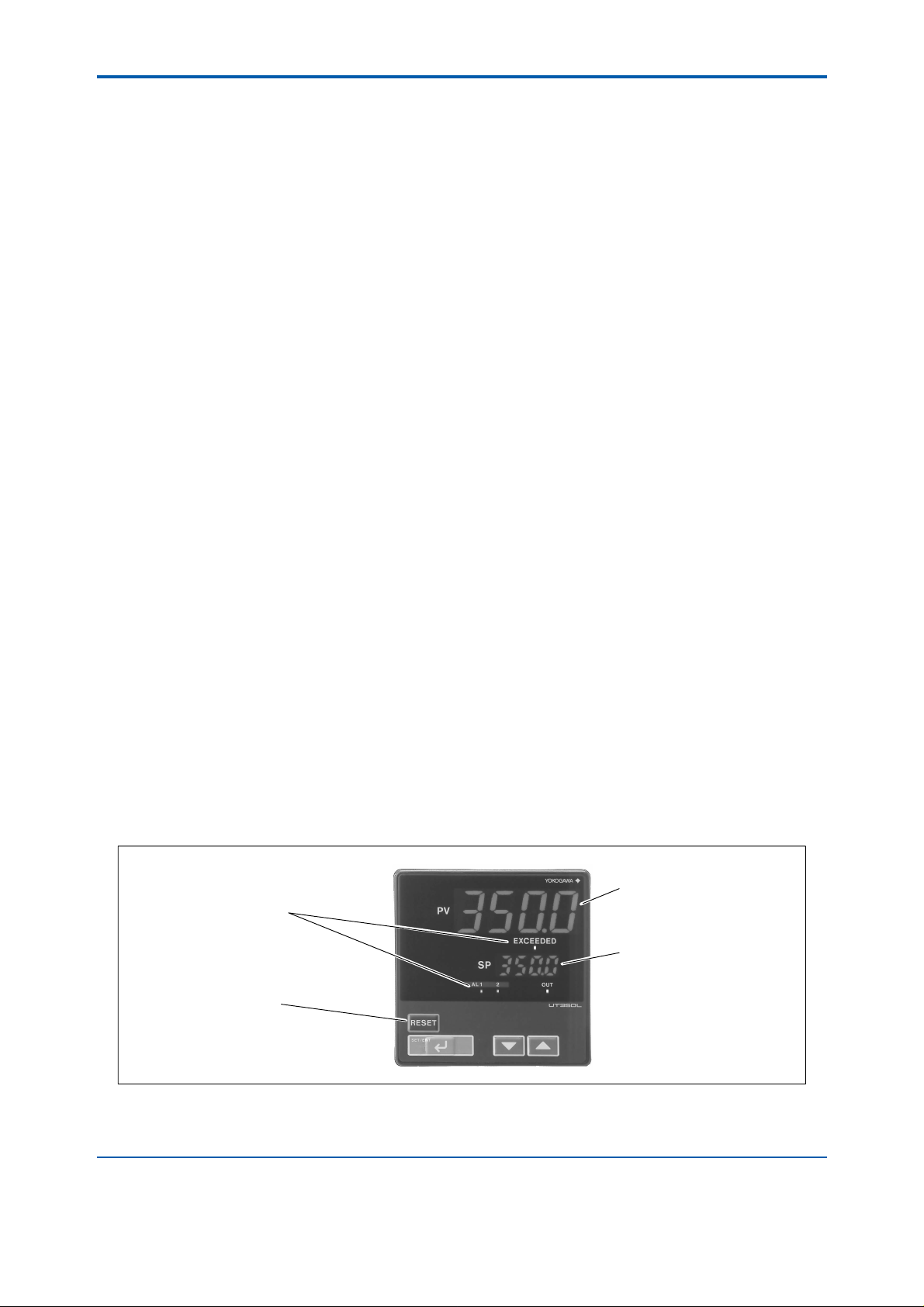
Status lamps
Alarm(AL1, 2), EXCEEDED,
OUT
LED display unit (for PV)
Displays PV, and error code when
error is detected.
LED display unit (for SP)
Displays setpoint (SP) and setting
item/value of parameters.
Operational keys
Increase/Decrease the setting data (▲,▼ )
Select parameter/Enter the setting data (SET/ENT)
Confirm and reset the output (RESET)
All Rights Reserved. Copyright © 1996, Yokogawa Electric Corporation GS 05D01D21-01E 4th Edition Apr. 02, 2007-00
Page 4

<<Contents>> <<Index>>
4
● Power Supply Specifications and Isolation
Power supply: Rated at 100 to 240 V AC (±10%), 50/60
Hz
Power consumption: Max. 20 VA (Max. 8.0 W)
Memory back-up: Non-volatile memory.
Withstanding voltage:
1500 V AC for 1 minute between primary and
secondary terminals.
1500 V AC for 1 minute between primary and ground
terminals.
1500 V AC for 1 minute between ground and second-
ary terminals.
500VAC for 1minute between two secondary termi-
nals.
Primary terminals = power and relay output terminals
Secondary terminals = Analog I/O signal terminals,
contact input terminals.
Insulation resistance: 20 MΩ or more when 500 V DC
voltage is applied between the power
terminals and ground terminal.
Grounding: Class D grounding (grounding resistance of
100 Ω or less)
Isolation specifications
Measured input terminal: Isolated from other I/O
terminals. Not isolated from internal
circuits.
Analog 4 to 20 mA output (retransmission) terminal:
Isolated from other I/O terminals and
internal circuits.
Relay contact control output terminals: Isolated from
other contact output terminals, other I/O
terminals and internal circuits.
Contact input terminals: Not isolated from other contact
input terminals, and communication
terminals. Isolated from other I/O terminals
and internal circuits.
Relay contact output terminals: Not isolated from other
relay contact output terminals. Isolated from
other I/O terminals and internal circuits.
RS-485 communication terminals: Not isolated from
contact input terminals. Isolated from other
I/O terminals and internal circuits.
Power supply terminals: Isolated from other I/O
terminals, ground terminal, and internal
circuits.
Ground terminal: Isolated from other I/O terminals,
power terminals, and internal circuits.
Thermocouple
RTD
Standard
signal
DC voltage
Input type
K
J
T
B
S
R
N
E
L (DIN)
U (DIN)
W (DIN)
Platinel 2
PR20-40
W97Re3-W75Re25
JPt100
Pt100
0.4 to 2V
1 to 5V
0 to 2V
0 to 10V
-10 to 20mV
0 to 100mV
Input range
code
1
2
3
4
5
6
7
8
9
10
11
12
13
14
15
16
17
18
30
31
35
36
37
40
41
50
51
55
56
Instrument range (˚C) Instrument range (˚F) Measurement accuracy
-200 to 1370˚C
-199.9 to 999.9˚C
-199.9 to 500.0˚C
-199.9 to 999.9˚C
-199.9 to 400.0˚C
0.0 to 400.0˚C
0 to 1800˚C
0 to 1700˚C
0 to 1700˚C
-200 to 1300˚C
-199.9 to 999.9˚C
-199.9 to 900.0˚C
-199.9 to 400.0˚C
0.0 to 400.0˚C
0 to 2300˚C
0 to 1390˚C
0 to 1900˚C
0 to 2000˚C
-199.9 to 500.0˚C
-150.0 to 150.0˚C
-199.9 to 640.0˚C
-199.9 to 500.0˚C
-150.0 to 150.0˚C
0.400 to 2.000
1.000 to 5.000
0.000 to 2.000
0.00 to10.00
-10.00 to 20.00
0.0 to 100.0
Scaling is enable in the following
4 range.
-1999 to 9999
-199.9 to 999.9
-19.99 to 99.99
-1.999 to 9.999
-300 to 2500˚F
0 to 2300˚F
-199.9 to 999.9˚F
-300 to 2300˚F
-300 to 750˚F
-199.9 to 750.0˚F
32 to 3300˚F
32 to 3100˚F
32 to 3100˚F
-300 to 2400˚F
-300 to 1800˚F
-300 to 1300˚F
-300 to 750˚F
-199.9 to 750.0˚F
32 to 4200˚F
32 to 2500˚F
32 to 3400˚F
32 to 3600˚F
-199.9 to 999.9˚F
-199.9 to 300.0˚F
-300 to 1180˚F
-199.9 to 999.9˚F
-199.9 to 300.0˚F
At or above 0˚C, ±0.1% ±1 digit of F.S.
Below 0˚C, ±0.2% ±1 digit of F.S.
At or above 400˚C, ±0.15% ±1 digit of F.S.
Below 400˚C, ±5% ±1 digit of F.S.
±0.15% ±1 digit of F.S.
±0.1% ±1 digit of F.S.
At or above 0˚C, ±0.1% ±1 digit of F.S.
Below 0˚C, ±0.2% ±1 digit of F.S.
±0.2% ±1 digit of F.S.
±0.1% ±1 digit of F.S.
At or above 800˚C, ±0.5% ±1 digit of F.S.
Below 800˚C, not guaranteed
±0.2% ±1 digit of F.S.
±0.1% ±1 digit of F.S.
±0.2% ±1 digit of F.S.
±0.1% ±1 digit of F.S.
±0.2% ±1 digit of F.S.
±0.1% ±1 digit of F.S.
All Rights Reserved. Copyright © 1996, Yokogawa Electric Corporation
GS 05D01D21-01E 4th Edition Apr. 02, 2007-00
Page 5

<<Contents>> <<Index>>
● Environmental Conditions
Normal operating conditions:
Ambient temperature: 0 to 50°C (40°C or less for
Temperature fluctuation: Max. 10°C/h
Ambient humidity: 20 to 90% RH (no condensation)
Magnetic field: 400 A/m or less
Continuous vibration (5 to 14 Hz): Peak-to-peak
Continuous vibration (14 to 150 Hz): 4.9 m/s
Short-period vibration: 14.7 m/s
Shock: 147 m/s
Installation altitude: 2,000 m or less above sea level
Attitude for installation: Max. 30° off vertical. Do not
Installation category based on IEC61010-1: II (See
Pollution degree based on IEC61010-1: 2 (See Note.)
Note:
• The “Installation category” implies the regulation for
impulse withstand voltage. It is also called the “Overvoltage category.” “II” applies to electrical equipment.
• “Pollution level” describes the degree to which a solid,
liquid or gas which deteriorates dielectric strength is
adhering. “2” applies to a normal indoor atmosphere.
mounting of instruments side-by-side)
amplitude of 1.2 mm or less
less
2
(15G) or less, 11 ms
2
(1.5G), 15s or less
2
(0.5G) or
install upside-down.
Note.)
5
Transportation and storage conditions:
Temperature : -25 to 70°C
Humidity : 5 to 95% RH
Effects of operating conditions:
Effect of ambient temperature:
For voltage or TC inputs: Whichever is greater,
± 1µV/°C or ±0.01% of F.S./°C
For RTD inputs: ±0.05°C/°C or less for RTD input
For analog output: ±0.05% of F.S./°C or less
Effect of power supply fluctuation (within rated voltage
range):
For analog input: Equal to or less than whichever is
greater, ± 1 µV/10 V or
± 0.01% of F.S./10 V
For analog output: ±0.05% of F.S./10 V or less
All Rights Reserved. Copyright © 1996, Yokogawa Electric Corporation GS 05D01D21-01E 4th Edition Apr. 02, 2007-00
Page 6

<<Contents>> <<Index>>
1
2
Relay contact output
3
Limit control output
NC
NO
COM
Contact rating: 250 V AC, 3 A
30 V DC, 3 A (resistance load)
23
24
RS-485 communication
* Wiring can only be carried out
for controllers with
communication functions.
Maximum baud rate: 9600 bps
25
26
27
SDB(+)
SDA(-)
RDB(+)
RDA(-)
SG
12
13
TC input
11
12
RTD input
13
12
13
mV/V input
A
b
B
-
+
-
+
12
13
Note: Connecting a 250
resistor to the terminals is
optional.
Model: X010-250-2 (resistor with M3.5 crimp-on terminal
lugs)
*
When receiving 4-20 mA DC current signals,
set the PV input type to 1-5 V DC (setpoint “41”).
䊏
Receiving 4-20 mA DC Current
Signals with the Controller
250
4-20mA
PV input
Confirmation of limit status
-
+
16
17
Retransmission output
4-20 mA DC
* PV retransmission is configured at factory
before shipment.
Load resistance: 600
or less
-
+
6
Alarm output
5
7
AL1
AL2
COM
Relay contact rating: 240 V AC, 1 A
30 V DC, 1 A (resistance load)
Relay
Alarm-1 output
Alarm-2 output
Common
UT
8
9
Power supply
10
L
N
Allowable range: 100 to 240 V AC (
10%)
(free voltage)
50/60 Hz shared
Power supply
CAUTION
Before carrying out wiring, turn off the power to
the controller and check that cables to be connected
are not alive with a tester or the like because
there is a possibility of electric shock.
Contact rating: 12 V DC, 10 mA or more
External contact input
DI
COM
Common
RESET when DI=ON
(However, setup parameter
DIS=DI)
DI
COM
+5V
Contact
Transistor contact
19
20
UT
19
20
21
23
24
25
26
27
30
11
12
13
14
15
16
17
18
19
20
1
2
3
4
5
6
7
8
9
10
6
■Terminal Wiring Diagrams
All Rights Reserved. Copyright © 1996, Yokogawa Electric Corporation
GS 05D01D21-01E 4th Edition Apr. 02, 2007-00
Page 7

<<Contents>> <<Index>>
■External Dimensions and Penel Cutout Dimensions
7
Unit: mm
96
96
11
100
Large bracket
91.8
Small bracket
1 to 10 mm (Panel thickness)
General installation Side-by-side close installation
[(N-1)96+92]117 min.
0
+0.8
92
(53)
145 min.
"N" stands for the number of controllers to be
installed.
92
+0.8
0
However, the measured value applies if N 5.
112
+0.8
0
92
+0.8
0
(25)
Normal Allowable Deviation=± (Value of JIS B 0401-1999 tolerance grade IT18) /2
■Model and Suffix Codes
Model Suffix code Description
UT350L
Type
Optional functions
Standard Accessories: User’s manual, mounting bracket
-0
0
1
Limit controller
Standard type
None
With communication
■Items to be Specified when Ordering
Model and suffix codes
All Rights Reserved. Copyright © 1996, Yokogawa Electric Corporation GS 05D01D21-01E 4th Edition Apr. 02, 2007-00
 Loading...