

Page 1
General
Specications
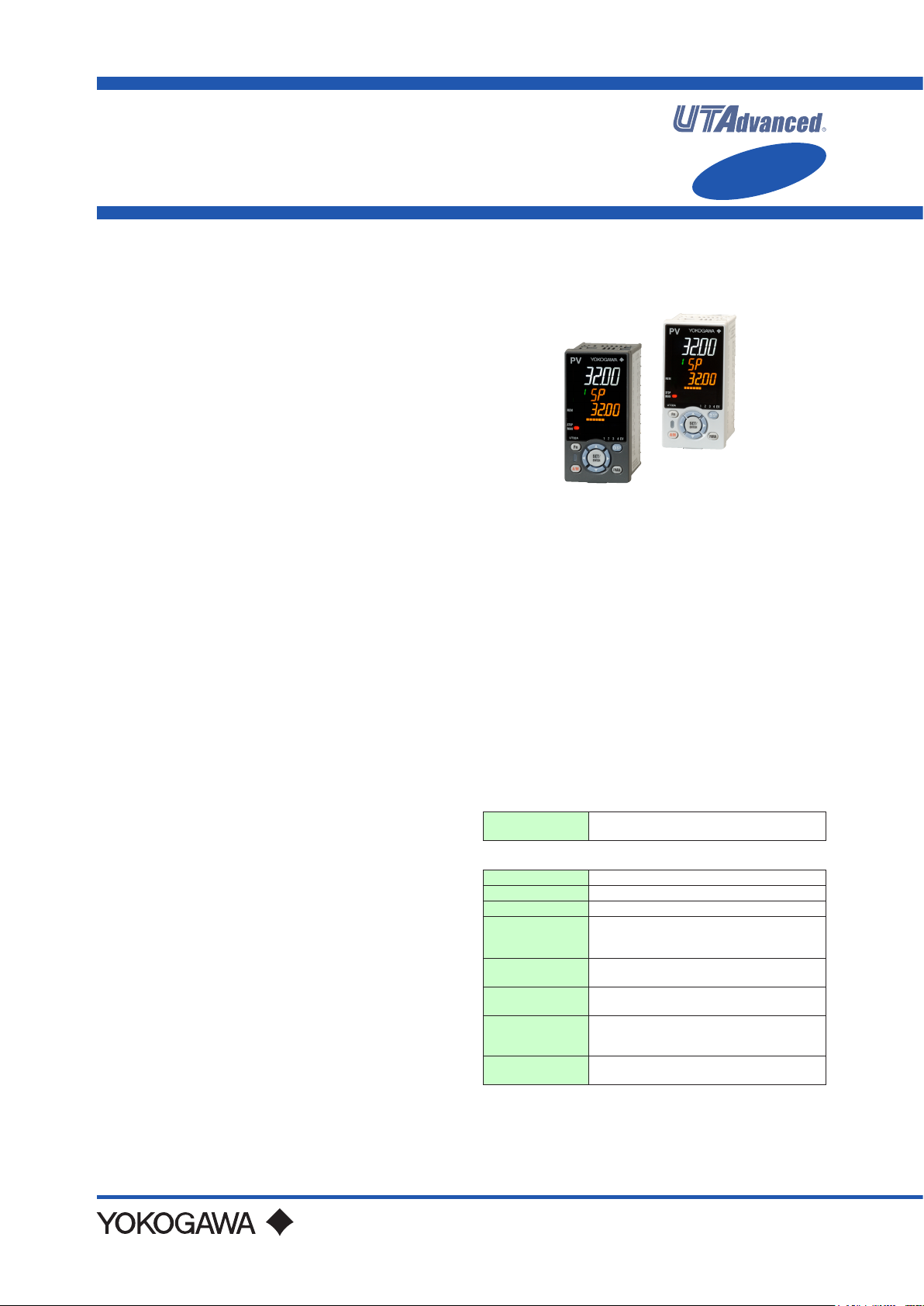
UT32A
Digital Indicating Controller
(Entry model)
GS 05P01F31-01EN
n Overview
The UT32A entry model digital indicating controller is
an easily congurable single-loop controller that can
generate relay, voltage pulse, or current signals for
control output. The short depth of the controller helps
save instrument panel space.
n Features
• A 14-segment, active (PV display color changing
function) color LCD display is employed.
Two ve-digit, high-resolution displays are possible.
Alphabet letters can be displayed in an easy-to-read
manner. The guide display shows parameter names.
• Easy to operate
Navigation keys (SET/ENTER and Up/Down/Left/
Right arrow keys) are employed to facilitate making
settings.
• 65 mm depth
The small depth enables the mounting in a thin and
small instrumented panel.
• Quick setting function
Setting only the minimum necessary parameters for
operation is possible.
• Equipped with a multitude of functions
Universal I/O is included as standard. PID control,
ON/OFF control, etc. are available.
• LL50A Parameter Setting Software (sold separately)
The parameters of UTAdvanced digital indicating
controller can be built from a PC using this software.
It makes data management even easier.
• Dust-proof and drip-proof
IP66 (for front panel) (Not applicable to side-by-side
close mounting.)
NEMA4 (Hose-down test only)
nFunctionalSpecications
ControlSpecications
(1) Control Mode
Single-loop control
(2) Control period
200 ms
Control Computation Function
(1) Types of control
• PID control
• ON/OFF control
(2) Control Computation Function
(a) Target setting point and the number of PID param-
eter groups
Respectively, four sets of target setpoints, alarm
setpoints, and PID parameters can be set.
Functional
Enhancement
(b) Selecting the PID parameter group
The following PID parameter groups can be selected.
• Target setpoint number (SPNO) (The PID number
can be set arbitrarily.)
• Measured input zone PID
• Target setpoint zone PID
• Reached target setpoint zone PID
(c) Auto-tuning
• Tuning results can be selected from two options,
Normal or Stable.
• Tuning output limit can be set.
(d) “Super” function: Overshoot-suppressing function
(e) “Super 2” function: Hunting-suppressing function
(f) STOP preset output function
(g) Input ERROR preset output function
(h) MANUAL preset output function
(3) Operation Mode Switching
Operation mode
switching
AUTO/MANUAL and RUN/STOP switching
(4) Control Parameter Setting Range
Proportional band 0.1 to 999.9%
Integral time 1 to 6000 sec. or OFF (using manual reset)
Derivative time 1 to 6000 sec. or OFF
ON/OFF control
hysteresis (one or two
hysteresis points)
Preset output
value
High/low output
limiter
Tight shut
function
Rate-of-change
limiter of output
0.0 to 100.0% of measured input range width
-5.0 to 105.0% (however, 0 mA or less cannot
be output)
-5.0 to 105.0%
Low limit setpoint < high limit setpoint
When manual control is carried out with 4 to
20 mA output, control output can be reduced to
about 0 mA.
0.1 to 100.0%/sec., OFF
Yokogawa Electric Corporation
2-9-32, Nakacho, Musashino-shi, Tokyo, 180-8750 Japan
Tel.: 81-422-52-7179 Fax.: 81-422-52-6619
GS 05P01F31-01EN
1st Edition Mar.31, 2015 (YK)
Page 2
2
Alarm Functions
• Types of Alarm
Measured value
alarm
Deviation alarm
Rate-of-change
alarm
Setpoint alarm
Output alarm Control output high/low limit alarm
Other alarms
PV (measured value) high/low limit alarm
Deviation high/low limit alarm
Deviation high and low limits alarm
Deviation within high and low limits alarm
Analog input PV high/low limit alarm
PV rate-of-change alarm
SP (setpoint) high/low limit alarm
Target SP high/low limit alarm
Target SP deviation high/low limit alarm
Target SP deviation high and low limits alarm
Target SP deviation within high and low limits alarm
Self-diagnosis alarm
FAIL
• Alarm Functions
Alarm output
action
Number of alarm
settings
Number of alarm
output points
Alarm stand-by action
Alarm latch (forced reset) function
Alarm hysteresis
Alarm ON/OFF delay timer
4
2
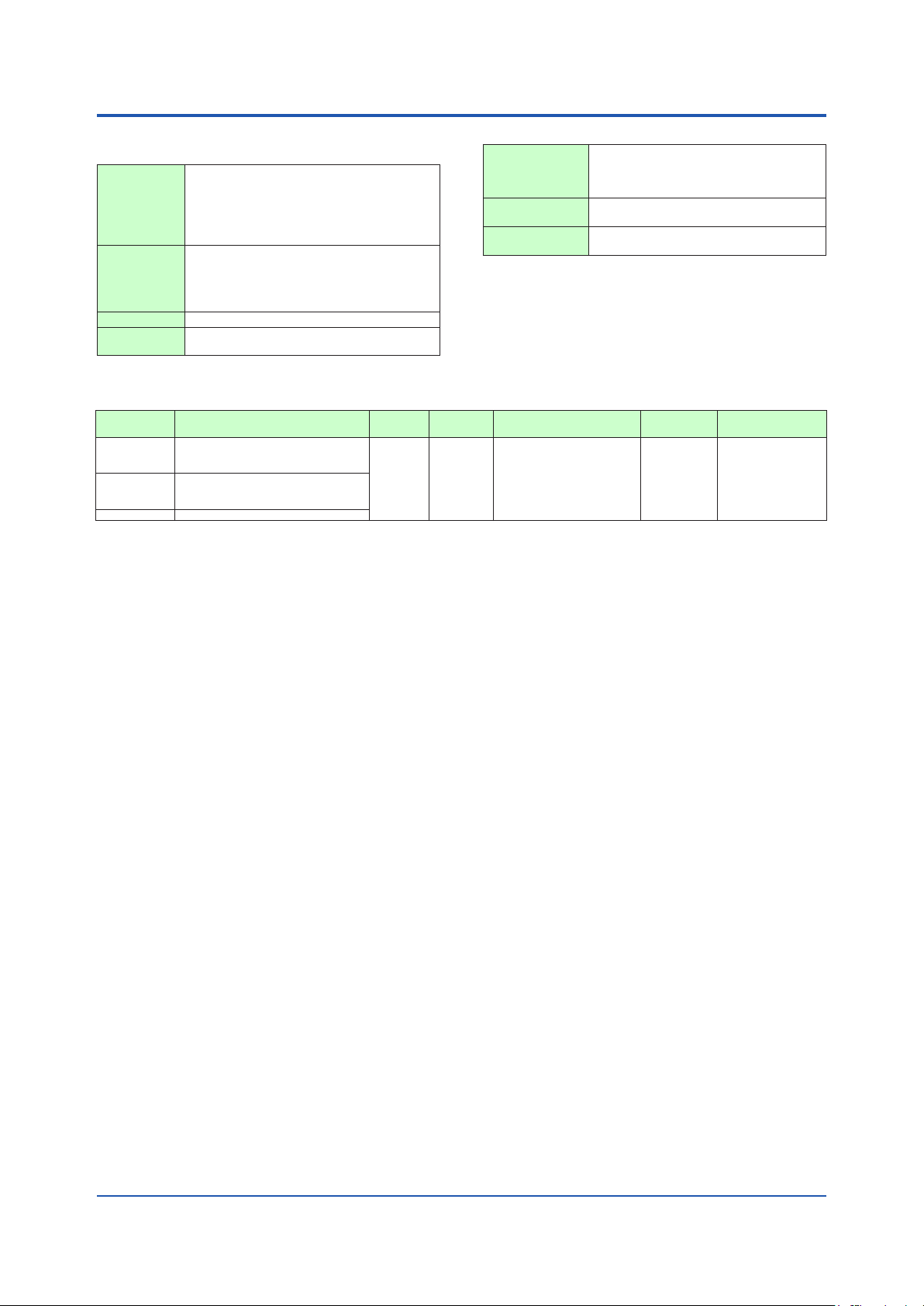
Communication Function
Function Method Interface Targets Max con-
Modbus
(RTU/ASCII)
PC link The proprietary Yokogawa protocol allowing
Ladder A protocol to communicate to PLCs.
A standard industry protocol allowing com-
munications between the controller and
devices such as PCs, PLCs, and DCSs.
communications to PCs, PLCs and touch
panels.
*1: UT digital indication controllers can be connected.
Slave RS-485 PLC and others, UT75A/UT55A/
UT52A/UT35A/UT32A/UP55A/
UP35A/UP32A/UM33A
(*1)
nection
31 units PV, ALM etc
Communication
Data
Physical Interface
RS-485
Standard: EIA RS-485
Communication method: Two-wire harf-duplex or four-wire harf-duplex, start-stop synchronization, and
Baud rate: 600,1200,2400,4800,9600,19200 or 38400bps
Maximum communication distance: 1200m
Terminating resistor: 220Ω (External)
non-procedural
All Rights Reserved. Copyright © 2015, Yokogawa Electric Corporation
GS 05P01F31-01EN Mar.31, 2015-00
Page 3
3
nHardwareSpecications
DisplaySpecications
• PV display
5-digit, 14-segment active color LCD (white/red)
Character height: 13.0 mm
• Data display
5-digit, 11-segment color LCD (orange)
• Bar graph display
12-segment color LCD (orange)
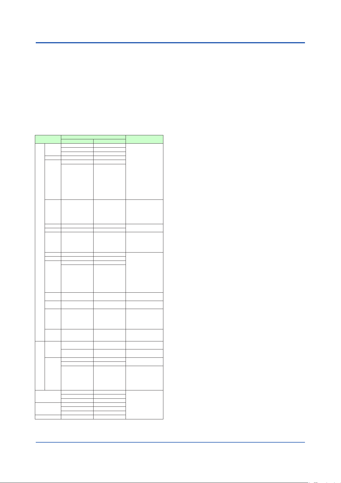
UniversalInputSpecications
• Number of input points: 1
• Types of input, instrument range, and measurement
accuracy (see the table below)
Types of input
-270.0 to 1370.0°C -450.0 to 2500.0°F ±0.1% of instrument
K
-270.0 to 1000.0°C -450.0 to 2300.0°F
-200.0 to 500.0°C -200.0 to 1000.0°F
J -200.0 to 1200.0°C -300.0 to 2300.0°F
-270.0 to 400.0°C -450.0 to 750.0°F
T
0.0 to 400.0°C -200.0 to 750.0°F
B 0.0 to 1800.0°C 32 to 3300°F
S 0.0 to 1700.0°C 32 to 3100°F
R 0.0 to 1700.0°C 32 to 3100°F
N -200.0 to 1300.0°C -300.0 to 2400.0°F
E -270.0 to 1000.0°C -450.0 to 1800.0°F ±0.1% of instrument
Thermocouple
L -200.0 to 900.0°C -300.0 to 1600.0°F
-200.0 to 400.0°C -300.0 to 750.0°F
U
0.0 to 400.0°C -200.0 to 1000.0°F
(*2)
0.0 to 2300.0°C 32 to 4200°F
W
Platinel
0.0 to 1390.0°C 32.0 to 2500.0°F
2
PR20-40 0.0 to 1900.0°C 32 to 3400°F
W97
0.0 to 2000.0°C 32 to 3600°F
Re3-W75
Re25
-200.0 to 500.0°C -300.0 to 1000.0°F
JPt100
-150.00 to 150.00°C -200.0 to 300.0°F
-200.0 to 850.0°C -300.0 to 1560.0°F
(RTD) 3-wire
Resistance-temperature
detector
Standard
signal
DC voltage
DC current 0.00 to 20.00 mA -
-200.0 to 500.0°C -300.0 to 1000.0°F
Pt100
-150.00 to 150.00°C -200.0 to 300.0°F
0.400 to 2.0000 V -
1.000 to 5.000 V -
4.00 to 20.00 mA -
0.000 to 2.000 V -
0.00 to 10.00 V -
-10.00 to 20.00 mV -
Instrument range
°C °F
Accuracy
range ±1 digit for 0°C
or more
±0.2% of instrument
range ±1 digit for less
than 0°C
However, ±2% of
instrument range
±1 digit for less than
-200°C of thermocouple
K ±1% of instrument
range ±1 digit for less
than -200°C of thermocouple T
±0.15% of instrument
range ±1 digit for 400°C
or more
±5% of instrument
range ±1 digit for less
than 400°C
±0.15% of instrument
range ±1 digit
±0.1% of instrument
range ±1 digit
±0.25% of instrument
range ±1 digit for less
than 0°C
range ±1 digit for 0°C
or more
±0.2% of instrument
range ±1 digit for less
than 0°C
However, ±1.5% of
instrument range ±1 digit
for less than -200.0°C of
thermocouple E
±0.2% of instrument
range ±1 digit
±0.1% of instrument
range ±1 digit
±0.5% of instrument
range ±1 digit for 800°C
or more
Accuracy not guaranteed for less than 800°C
±0.2% of instrument
range ±1 digit
±0.1%
of instrument
range ±1 digit
±0.1% of instrument
range ±1 digit
±0.1%
range ±1 digit
±0.1% of instrument
range ±1 digit
±0.1% of instrument
range ±1 digit
(*1)
of instrument
(*1)
The accuracy is that in the standard operating conditions: 23 ±2°C, 55 ±10%RH, and power frequency at
50/60 Hz.
*1:
±0.3°C and ±1 digit in the range between 0 and 100°C
±0.5°C ±1 digit in the range between -100 and 200°C
*2:
W-5% Re/W-26% Re (Hoskins Mfg.Co.), ASTM E988
•
Applicable standards: JIS, IEC and DIN (ITS-90) for thermocouples and resistance-temperature detectors (RTD)
• Input sampling period: Synchronized to control period
• Burnout detection
Upscale and downscale of function, and OFF can
be specied for the standard signal of thermocouple and resistance-temperature detector (RTD).
For integrated signal input, 0.1 V or 0.4 mA or less
is judged as a burnout.
• Input bias current: 0.05 μA (for thermocouple and
resistance-temperature detector (RTD))
• Resistance-temperature detector (RTD) measured
current: About 0.16 mA
• Input resistance
1 MΩ or more for thermocouple/mV input
About 1 MΩ for voltage input
About 250 Ω for current input (with built-in shunt
resistance)
• Allowable signal source resistance
250 Ω or less for thermocouple/mV input
Effect of signal source resistance: 0.1 μV/Ω or less
2 kΩ or less for DC voltage input
Effect of signal source resistance: about
0.01%/100 Ω
• Allowable wiring resistance
Up to 150 Ω per line for resistance-temperature
detector (RTD) input (conductor resistance
between the three lines shall be equal)
Effect of wiring resistance: ±0.1°C/10 Ω
• Allowable input voltage/current
±10 V DC for thermocouple/mV/mA or resistance temperature detector (RTD) input
±20 V DC for V input
±40 mA DC for mA input
• Noise reduction ratio
40 dB or more (at 50/60 Hz) in normal mode
120 dB or more (at 50/60 Hz) in common mode
• Reference junction compensation error
±1.0°C (15 to 35°C)
±1.5°C (-10 to 5°C and 35 to 50°C)
AnalogOutputSpecications(Sufx code:-C)
• Number of points
Control output: 1 point
• Output functions
Current output
• Current output
4 to 20 mA DC or 0 to 20 mA DC/load resistance
600 Ω or less
• Current output accuracy
±0.1% of span (however, ±5% of span for 1 mA
or less)
The accuracy is that in the standard operating
conditions: 23 ±2°C, 55 ±10%RH, and power
frequency at 50/60 Hz
AnalogOutputSpecications(Sufx code:-V)
• Number of points
Control output: 1 point
• Output functions
Voltage pulse output
All Rights Reserved. Copyright © 2015, Yokogawa Electric Corporation
GS 05P01F31-01EN
Mar.31, 2015-00
Page 4

4
The circuits divided by lines are insulated mutually.
• Current output
4 to 20 mA DC or 0 to 20 mA DC/load resistance
600 Ω or less
• Voltage pulse output
Application: time proportional output
ON voltage: 12 V or more/load resistance of 600
Ω or more
OFF voltage: 0.1 V DC or less
Time resolution: 10 ms or 0.1% of output value,
whichever is larger
ContactInputSpecications(Sufx code:-R)
• Types of contact and number of points
Control relay output: one, 1c-contact point
• Input type: no-voltage contact input or transistor contact input
• Contact rating
1c-contact: 3 A at 250 V AC or 3 A at 30 V DC
(resistance load)
*: The control output should always be used with a
load of 10 mA or more.
• Application: ON/OFF output or time proportional
output
• Time resolution for control output: 10 ms or 0.1% of
output value, whichever is larger
RelayContactOutputSpecications
• Types of contact and number of points
Alarm output: 2, 1a-contact points (Common is
separated)
• Contact rating
1a-contact:
For alarm output: 1 A at 240 V AC or 1 A at
30 V DC (resistance load)
*: The alarm output should always be used with a load of 1
mA or more.
• Application: alarm output, FAIL output, etc.
24VDCLoop PowerSupplySpecications
(for /LP Option)
•
Application: Power is supplied to the 2-wire transmitter.
• Supply voltage: 21.6 to 28.0 V DC
• Rated current: 4 to 20 mA DC
• Maximum supply current: About 30 mA (with short-
circuit current limiting circuit)
Safety and EMC Standards
• Safety:
Compliant with IEC/EN61010-1 (CE), IEC/EN61010-
2-030 (CE), approved by CAN/CSA C22.2 No.
61010-1 (CSA), approved by UL61010-1.
Installation category: II
Pollution degree: 2
Measurement category: I (CAT I) (UL, CSA)
O (Other) (CE)
Rated measurement input voltage: Max. 10 V DC
Rated transient overvoltage: 1500 V (
*:
This is a reference safety standard value for measurement category I of IEC/EN/CSA/UL61010-1. This value is
not necessarily a guarantee of instrument performance.
*)
• EMC standards:
Compliant with
CE marking
EN 61326-1 Class A, Table 2 (For use in industrial
locations),
EN 61326-2-3
*:
The instrument continues to operate at a measurement
accuracy of within ±20% of the range during testing.
EN 55011 Class A, Group 1
EN 61000-3-2 Class A
EN 61000-3-3
EMC Regulatory Arrangement in Australia and New Zealand
EN 55011 Class A, Group 1
• KC marking: Electromagnetic wave interference
prevention standard, electromagnetic wave protection
standard compliance
PowerSupplySpecicationsand Isolation
• Power supply
Rated voltage: 100 to 240 V AC (+10%/-15%), 50/60 Hz
/DC option is specied)
• Power consumption: 15 VA (For the /DC option. DC:
7 VA, AC: 11 VA)
• Storage: Nonvolatile memory
•
Allowable power interruption time: 20 ms (at 100 V AC)
• Withstanding voltage
2300 V AC for 1 minute between primary and
secondary terminals (UL, CSA)
3000 V AC for 1 minute between primary and
secondary terminals (CE)
1500 V AC for 1 minute between primary terminals
500 V AC for 1 minute between secondary
terminals
(Primary terminals = Power (*) and relay output
terminals, Secondary terminals = Analog I/O signal
terminals, communication terminals,
and functional grounding terminals.)
*: Power terminals for 24 V AC/DC models are the
• Insulation resistance
Between power supply terminals and a grounding
terminal: 20 MΩ or more at 500 V DC
• Isolation specications
24 V AC/DC (+10%/-15%) (When the
secondary terminals.
All Rights Reserved. Copyright © 2015, Yokogawa Electric Corporation
PV (universal) input terminal
Control (voltage pluse, analog) output terminal
Control relay (c-contact) output terminal
Alarm-1 relay (a-contact) output terminal
Alarm-2 relay (a-contact) output terminal
RS485 communication terminal
24 V DC loop power supply terminal
GS 05P01F31-01EN Mar.31, 2015-00
Internal
circuits
Power
supply
Page 5

Environmental Conditions
Normal operating conditions
• Ambient temperature: -10 to 50°C (-10 to 40°C for
side-by-side mounting of controllers)
• Ambient humidity: 20 to 90% RH (no condensation)
• Magnetic eld: 400 A/m or less
• Continuous vibration (at 5 to 9 Hz) Half amplitude of
1.5 mm or less
(at 9 to 150 Hz) 4.9 m/s2 or less, 1 oct/min for 90 minutes each in the three axis directions
• Rapid vibration: 14.7 m/s2, 15 s or less
• Impact: 98 m/s
2
or less, 11 msec.
• Installation altitude: 2,000 m or less above sea level
• Warm-up time: 30 minutes or more after the power is
turned on
• Start-up time within 10 s
Transportation and Storage Conditions
• Temperature: -25 to 70°C
• Temperature change rate: 20°C per hour or less
• Humidity: 5 to 95%RH (no condensation)
Effects of Operating Conditions
• Effect of ambient temperature
For voltage or TC input:
±1 μ V/°C or ±0.01% of F.S. (instrument
range)/°C, whichever is greater
For RTD input:
±0.05°C/°C (ambient temperature) or less
For current input:
±0.01% of F.S. (instrument range)/°C
For analog output:
±0.02% of F.S./°C or less
• Effect of power supply uctuation:
For analog input: ±0.05% of F.S. (instrument range)
or less
For analog output: ±0.05% of F.S. or less
(Each within rated voltage range)
5
All Rights Reserved. Copyright © 2015, Yokogawa Electric Corporation
GS 05P01F31-01EN
Mar.31, 2015-00
Page 6

n Block Diagram
Equipped as standard
Single Loop Control
PV input
PV
6
Input type
Input unit
Input range/scale
PV input bias
PV input filter
IN
UNIT
RH, RL SDP SH, SL
BS
FL
Input error preset output
Manual preset output
Manual operation
Output limiter
Preset output
PV display SP display
EPO
When sensor burnout occurs
MPON
OH, OL OLMT
PO
MAN
A/M
Communication
Ratio bias computation
Control computation
CNT ALG
Output limiter
Normal
AUTO
S/R
RT RBS
LOCALREMOTE
R/L
SP limiter
SP ramp rate
OH, OL
AUTO (ON)/MAN (OFF) switch
STOP (ON)/RUN (OFF) switch
RUNSTOP
SPH, SPL
UPR, DNR TMU
SPNO SP
Target setpoints 1 to 4
For optional suffix code /LP
24 V loop
power supply
LPS
OUTOUT AL2AL1
CurrentRelay
(Suffix code: -C)(Suffix code: -R) (Suffix code: -V)
OUT
Voltage pulse
Legend
Terminal Parameter Function
Analog signal Contact signal Front panel key
Equipped as standard
Alarm
Alarm 1
Alarm 2
(PV high limit)
(PV low limit)
All Rights Reserved. Copyright © 2015, Yokogawa Electric Corporation
GS 05P01F31-01EN Mar.31, 2015-00
Page 7

n Terminal Arrangement
as standard)
Relay contact rating: 240 V AC, 1 A
100-240 V AC
50/60 Hz shared
(Suffix code: Type 2=1)
RS-485 communication
RS-485
SDB(+)
SDA(-)
RDB(+)
RDA(-)
(Suffix code: Type1=-R)
Control output
Relay contact output
NC
101
NO
102
COM
103
Contact rating: 250 V AC, 3 A
30 V DC, 3 A (resistance load)
Contact output
External contact output (relay)
Alarm-2 output
(PV low limit)
Common
Alarm-1 output
(PV high limit)
Common
30 V DC, 1 A (resistance load)
RS485
301
302
SG
303
304
305
OUT
ALM
106
AL2
107
108
AL1
109
(Optional suffix code /LP)
(Equipped
as standard)
UT
24 V DC loop power supply
24 V DC loop power supply
21.6-28.0 V DC
(Max. 30 mA DC)
LPS24
+
305
-
306
E1-terminal area
101
-112
101
102
103
104
105
106
107
108
109
110
111
112
(
Suffix code: Type 2=1 and
optional suffix code /LP)
RS-485 communication/24 V DC loop power supply
301
302
303
304
305
306
201
-212
201
202
203
204
207
208
RS-485
RSB(+)
RSA(-)
301
302
SG
303
24 V DC loop power supply
21.6-28.0 V DC
(Max. 30 mA DC)
+
305
-
306
RS485/LPS24
PV input
TC input RTD input
+
-
Current (mA) input
-
+
Factory default:
PV input type is
undefined.
PV
202
203
Voltage (mV, V) input
203
204
(Equipped
A
201
b
202
B
203
+
202
-
203
7
Power supply
power supply
N
L
Allowable range:
100-240 V AC (+10%/-15%)
(free voltage)
24 V AC/DC power supply
110
111
112
(24 V AC/DC power supply:
Optional suffix code /DC)
N
-
110
L
+
111
112
(Suffix code: Type1=-V or -C)
Control output
Current/voltage pulse output
+
0-20 mA DC,
4-20 mA DC,
Voltage pulse (12 V)
207
-
208
OUT
All Rights Reserved. Copyright © 2015, Yokogawa Electric Corporation
GS 05P01F31-01EN
Mar.31, 2015-00
Page 8

n External Dimensions and Panel Cutout Dimensions
11
Terminal cover (option)
• General mounting
48
65
Bracket
20
8
Unit:mm
92
(53)
+0.8
96
1 to 10 mm (panel thickness)
• Side-by-side close mounting
70 min.
0
+0.8
92
145
min.
0
+0.6
45
(25)
0
“N” stands for the number of controllers to be
installed.
However, the measured value applies if N≥5.
Normal tolerance:
±(value of JIS B 0401-1998 tolerance class IT18)/2
91.6
94.6
Bracket
[(N-1)×48+45]
105.2
+0.6
0
n Construction, Mounting, and Wiring
• Dust-proof and drip-proof: IP66 (Front panel) (Except for side-by-side close mounting)/NEMA4 *
*: Hose-down test only
•
Material: Polycarbonate resin (Flame retardancy: UL94 V-0)
• Case color: White (Light gray) or Black (Light Charcoal gray)
• Weight: 0.5 kg or less
• External dimensions (mm): 48 (width) x 96 (height) x 65 (depth from the panel surface)
• Mounting: Direct panel mounting; mounting bracket, one each for upper and lower mounting
• Panel cutout dimensions (mm): 45+
• Mounting position: Up to 30 degrees above the horizontal. No downward titling allowed.
• Wiring: M3 screw terminal with square washer (signal wiring and power)
0.6/0
(width) x 92+
0.8/0
(height)
nModelandSufxCode
Model Sufxcode Optionalsufxcode Description
UT32A
Type 1:
Basic control
Type 2:Functions
Type 3:Fixed code 0 None
Display language
Case color
Fixed code -00 Always "-00"
Optional sufx codes
-V
-C
-R
0 None
1 RS-485 communication (Max. 38.4 kbps, 2-wire/4-wire)
-1 English (Default. Can be switched to other language by the setting.)
(*2)
-2 German (Default. Can be switched to other language by the setting.)
-3 French (Default. Can be switched to other language by the setting.)
-4 Spanish (Default. Can be switched to other language by the setting.)
0 White (Light gray)
1 Black (Light charcoal gray)
/LP 24 V DC loop power supply
/DC Power supply 24 V AC/DC
/CT Coating
/CV Terminal cover
*1: When the /LP option is specied, the RS-485 communication of the Type 2 code “1” is 2-wire system.
*2: English, German, French, and Spanish are available for the guide display.
*3: When the /CT option is specied, the UT32A does not conform to the safety standards (UL and CSA) and CE marking (Prod-
ucts with /CT option are not intended for EEA-market).
All Rights Reserved. Copyright © 2015, Yokogawa Electric Corporation
Digital Indicating Controller (Power supply: 100-240 V AC) (provided with
2 DOs)
Voltage pulse output type
Current output type
Relay output type
(*1)
(*3)
GS 05P01F31-01EN Mar.31, 2015-00
Page 9

nItemstobespeciedwhenordering
Model and sufx codes, whether User’s Manual and
QIC required.
n Standard accessories
Brackets (mounting hardware), Unit label, Operation
Guide
n Special Order Items
Model code
LL50A
X010
*: Necessary to input the current signal to the voltage
input terminal.
Name
Terminal cover (for UT32A) UTAP002
User’s Manual (CD) UTAP003
User’s Manual
Product user’s manuals can be downloaded or viewed
at the following URL. To view the user’s manual, you
need to use Adobe Reader 7 or later by Adobe Sys-
tems.
URL:http://www.yokogawa.com/ns/ut/im/
Sufxcode Description
-00 Parameter Setting Software
See the General Specications
Resistance Module
(*)
Model
9
All Rights Reserved. Copyright © 2015, Yokogawa Electric Corporation
Subject to change without notice.
GS 05P01F31-01EN Mar.31, 2015-00
 Loading...