

Page 1
<<Contents>> <<Index>>
C
3
5
6
3
5
6
7
8
9
J
U
0
J
00
0
600
C
C
00
C
999
C
C
999
C
C
00
C
0
C
C
00
C
C
500
C
3
5
6
8
9
0
3
5
6
8
9
0
3
0.0
600.0
C
J
S
U
2
0
J
00
0
V
V
V
0
V
0
C
999.9
0
00
C
900.0
C
0
C
0
390
0.0
0
C
199.9
200.0
500.0
C
0.0
0
0.000
000
0.00
00
e
e
31
32
33
34
35
36
37
3
5
6
7
8
3
999
00
999
999
50
9
00
F
999
e
s
e
)
31
32
33
34
35
36
37
38
39
0
3
5
6
8
32.0
999.9
32.0
0
300.0
0
300.0
800.0
3
00
3
00
3
00
300
600
300
50
3
500
32.0
0
300
400
)F)
g
.
,
9
e
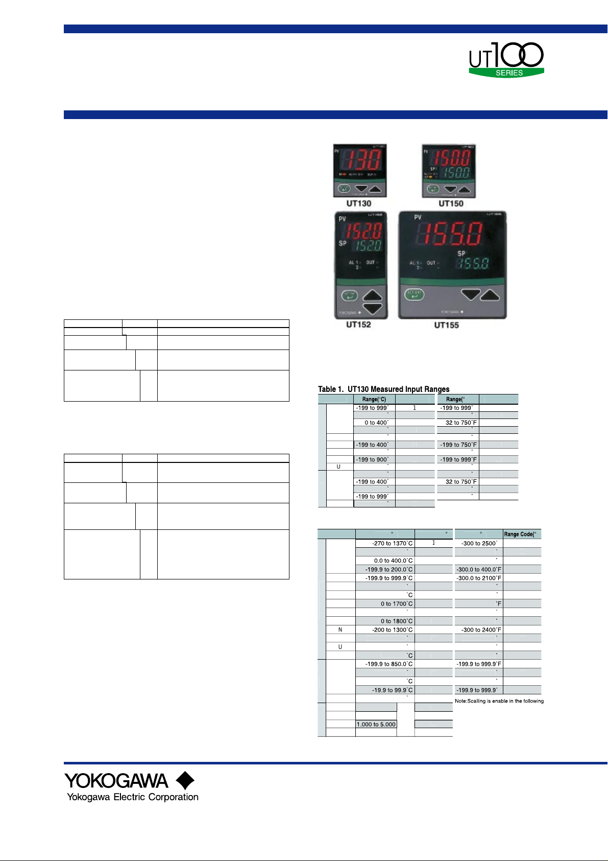
General
Specifications
Models
UT130, UT150/UT1 52/UT155
Temperature Controllers
GS 05C01E02-01E
■General
UT100 series temperature controllers provide only the
functions and size you require for your application. 1/16,
1/8 and 1/4 DIN sizes are available. Easy-to-read displays
show input and the setpoint. T/C or RTD inputs are
standard and the output type is selectable: ON/OFF,
voltage pulse or DC current. The controllers operate in an
Automatic mode only. Optional alarm contact outputs,
retransmission output, contact input setpoint selection and
RS485 communication are available. Each features dynamic
self-tunig function for easy start up. Super Control fuzzy
logic for overshoot suppression is a proven champion.
■Model and Suffix Codes
Model Suffix code Description
UT130 Temperature controller
Control output for standard
type (or for heating)
Control output for cooling
Option
Note1:/AL option cannot be specified when /HBA option is specified. /HBA option already includes the /AL
option.
Note2:/HBA option cannot be specifed at the same time.
Note3:When specifying the /RS option, be sure to order the required number of copies of Communication
Functions Instruction Manual separeately. You will not be supplied and instruction manual just
because you order for the /RS option.
Model Suffix code Description
UT150
UT152
UT155
Control output for standardtype (or for heating)
Control output for cooling
Option
Note1:/HBA option cannot be specifed when 4 to 20 mA output (heating-side) is specifed.
Note2:/AL option cannot be specifed when /HBA option is specifed.
/HBA option already includes the /AL option.
Note3:/HBA option and /RET option cannot be specifed at the same time.
Note4:/EX option and /RS option cannot be specifed at the same time.(model UT150 only)
Note5:/EX option includes contact input 1 (for switching between the SP1 and SP2 target setpoints using
external contacts) and contact input 2 (for enabling the timer).
Note6:When specifying the /RS option, be sure to order the required number of copies of Communication
Functions Instruction Manual separeately. You will not be supplied and instruction manual just
because you order for the /RS option.
–R
–V
–R
–V
–A
Relay output (time-proportional PID or on/off control)
Voltage pulse output (time-proportional PID)
N
No cooling output (standard type)
R
Relay output (time-proportional PID or on/off control)
V
Voltage pulse output (time-proportional PID)
/AL
Alarm outputs (2 points)
/HBA
Heater disconnection alarm
(includes optional /AL function)
/RS
Communication function
/V24
Power Supply 24V DC / 24V AC
Temperature controller
Relay output (time-proportional PID or on/off control)
Voltage pulse output (time-proportional PID)
4 to 20mA output (continuous PID)
N
No cooling output (standard type)
R
Relay output (time-proportional PID or on/off control)
V
Voltage pulse output (time-proportional PID)
A
4 to 20mA output (continuous PID)
/AL
Alarm outputs (2 points)
/HBA
Heater disconnection alarm
(includes optional /AL function)
/EX
SP1/SP2 switching, starting of timer, and RUN/STOP
switching by external contacts
/RET
PV retransmission output in 4 to 20mA
/RS
Communication function
/V24
Power Supply 24V DC / 24V AC
(Note1)
(Note2)
(Note2)
(Note4)(Note5)
(Note3)
(Note1)
(Note1)
(Note4)
(Note3)
(Note1)
(Note2)
(Note2)
(Note3)
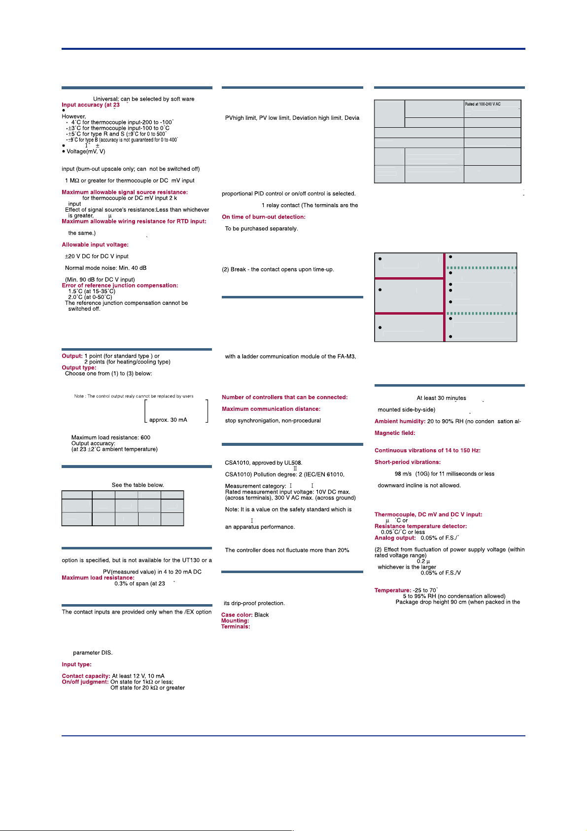
■Measured Value Input
The UT100 series allows you to freely change the input type
by software.
Input Typ
to
-199 to 2
-199 to
hermocouple
Pt10
Pt1
-199 to
-199 to 4
-199 to 85
-199 to 2
-199 to
Table 2.UT150/152/155 Measured Input Range
Input Typ
-199.9 to 400.
-199.9 to
hermocouple
-199.9 to
Platinel
Pt10
Pt1
e
to100m
0 to 5
1 to 5
C volta
to 10
-199.9 to 400.
-
-199.9 to
Range Cod
1
1
1
1
1
1
Range(C)Range Code(C
to
to 17
to 1
to 400.
to
to 100.
to 5.
to 10.
1
1
1
1
1
1
2
Not
2
F)Range Cod
2 to
-199 to 4
-199 to
-199 to
-199 to 7
-199 to 99
-199 to 4
-199 to
Range(F
to
to 750.
-
to 750.
-
to 1
2 to 31
2 to 31
2 to 32
-
to 1
-
to 7
2 to 2
to 750.
-
to
4 range
-1999 to 9999, -199.9 to 999.9
-199.99 to 99.99, -1.999 to 9.99
4
4
4
4
4
4
4
4
4
4
GS 05C01E02-01E
© Copyright Dec. 2000 (MC)
2nd Edition Jun. 2004 (YK)
Page 2
<<Contents>> <<Index>>
t
)
Thermocouple:
C
C
)
)
C
t
0.3%
500 ms
t
50
0
00
2
C / 10
um
)
B
r
)
s
0
C
0
C/
s
)
s
C
:
s
s
S
ude
000
s
(1)
s
/
0.02%
r
C
:
,
:
s
C
y:
S
)
t
y
t
C
)
t
(3)
t
A
n
y:
y
:
s
t
g
600
y:
C
)
s
s
n
C
n
s
S
s
g
)
)
g
g
)
t
UT130
UT150
UT152
UT155
9.0
9.0
9.5
5
20.0
y
(mm)
y
(mm)
/A
s
(
)
g
t
s
(
)
sconnectio
on
(
)
e-
A
)
d
S
)
)
:
(1)
y
.
C
l
g
a
adder communicatio
C
e
5
1
m
C
-
aud rate
s
.
(
)
)
)
.
.
.
C
[
].
e
g
)
y
ge
y
n
y
50
z
)
m
y
500
e
i
ed
g
ge
n
ce
(
)
B
(
)
at
500
C
r
i
.
g
.
.
on
b
.
r
ernal circu
.
s
(
)
y
contacts
)
y
C
i
s
A
(
)
)
r
)
S
ce:
600
r
s
(
)
■Hardware Specifications
2
Measured Value (PV) Inpu
Input: 1 poin
Input type:
Sampling period for measured value input:
Burn-out detection: Functions for thermocouple or RTD
1digi
C ambient temperature
C
C
Input resistance:
Approx. 1 M for DC V inpu
2
for DC V
.2 V/1 or0.01% / 1
10/wire (The resistance values of three wires must be
Effect of wiring resistance:0.
maxim
10 V DC for thermocouple or DC mV input
Noise rejection ratio (50/60Hz
Common mode noise: Min. 120 d
Applicable Standards:
Thermocouple and resistance temperature detecto
JIS/IEC/DIN (ITS90
Control Output
(1) Relay contact outpu
Contact capacity: 3 A at 240 V AC or 3 A at 30 V D
(with resistance load
(2) Voltage pulse outpu
On voltage:12 to 18 V DC
Off voltage:0.1 V DC or less
Current outpu
Output signal: 4 to 20 m
load resistan
or greate
hort-circuit current:
0.3% of spa
Displa
Measured value and setpoint displa
4-digit, 7-segment LED displa
Character height
PV displa
SP displa
17.513.513.
N
Status indicator lamps: LED
Retransmission Outpu
The retransmission output is provided only when the /RET
heating/cooling type.
nal:
Output si
Output accurac
temperature
ambient
Contact Input
is specified, but are not available for the UT130.
Functions:
(1) Switching over two setpoints (SP1 and SP2
(2) Starting a timer(See the following "Alarm Functions."
(3) RUN/STOP switchin
Specify two functions from the three functions usin
Input: 2 points (with the shared common terminal
inpu
Non-voltage contact or transistor contact
Alarm Function
Alarm Function
Option Code /AL or /HBA
Alarm types: 22 types (Waiting action can be set by
software):
tion low limit, De-energized on deviation high limit,
De-energized on deviation low limit, Deviation high
and low limits, High and low limits within deviation,
De-energized on PV high limit, De-energized on PV
low limit, self-dia
Alarm output: 2 relay contact
Relay contact capacity: 1 A at 240 V AC or
1 A at 30 V DC
Heater Di
Option Code /HBA
The heater disconnection alarm is available when tim
Heater current setting range: 1 to 80
Alarm output:
same as those of the /AL option.
ensor: CTL-6-S-H or CTL-12-S36-8 (URD Co. Ltd.
Timer Function (Option Code /EX/AL or /EX/HBA
The output contact status changes when the preset
time has passed since "TMR" contact turned on. The
contact action can be selected by software from
Make contact - the contact closes upon time-up.
nostic alarm, FAIL outpu
with resistance load
n Alarm Functi
Min. 0.2 secon
Input contact type:See "Contact Inputs"above.
ommunication Functio
The communication function is provided onl
/RS option is specified
ommunication Protoco
Personal computer link:Used for communication
with a personal computer, or UT link module of the
FA-M3 controller (from Yoko
tion).
L
or a programmable controller of other manufacturers.
MODBUS communication:Used for communication
with equipment featuring the MODBUS protocol.
ommunication Interfac
Applicable standards: Complies with EIA RS-48
awa Electric Corpor
n:Used for communication
Up to 3
ommunication method: Two-wire half-duplex, start
B
: 2400, 4800, or 9600 bp
when the
1,200
afety and EMC Standard
Safety:
Compliant with IEC/EN61010-1: 2001, approved by
Installation category: CAT
CSA1010
IEC/EN61010,
(CAT.: IEC/EN61010
Rated trasient overvoltage: 1500 V (Note
assumed by IEC/EN61010-1 in measurement
category
EMC standards: Complies with EN61326
All wires except those for the power supply and relay
contact output terminals are shielded
, and is not the value which guarantees
even when noise is applied
Construction, Mounting, and Wirin
onstruction: Dust-proof and Drip-proof front panel
conforming to IP65 [Models UT130/UT150] and IP55
Models UT152/UT155
For side-by-side close installation, the controller loses
Casing: ABS resin and polycarbonat
Flush panel mountin
Screw terminals
Power Supply and Isolatio
Power Supply (Common for All Models
Power suppl
Maximum power consumptio
Memor
Withstandin
volta
Insulatio
resistan
Note 1 : The primary terminals are the power supply te
minals and relay output terminals. The secondary term
nals are the analog input and output terminals, the voltage
pulse output terminals, and the contact input terminals
Note 2 : The withstanding voltage is specified as 2300 V
AC per minute to provide a mar
Note 3 : 24V power supply is the secondary terminal
Isolati
The bold lines below indicate reinforced isolation, and the
roken line indicates functional isolation
Note 1: The /EX option is not available for the UT130.
Note 2: Neither the measured value input terminals, CT input terminals fo
the /HBA option, nor input terminals for the /EX option are isolated from the
int
Note 3: The UT130 does not have the 4 to 20 mA DC output
Volta
Frequenc
Between primary terminals
and secondary terminals
See Notes 1 and 3.
etween primary terminals
and secondary terminals
See Notes 1 and 3.
Power supply terminal
100-240V AC
Control output
terminals: rela
Alarm output terminals
(2 relay contacts
it.
AC/DC when "/V24" is spec
fi
or 60 H
8 VA maximum(4W maximum
when"/V24" is specified : 3W maximu
Non-volatile memor
1
V AC for 1 minut
Note 2
20M
or more
V D
in of safety
Power Suppl
24V DC/24V A
Measured value input term
nal
CT input terminals for /HB
2 input terminals for /EX
Note 1
Internal circuit (Note 2
Control output terminals:
4-20 mA DC output o
voltage pulse (Note 3
RS-485 terminals for /R
Environmental Condition
Normal Operating Condition
Warm-up time:
Ambient temperature: 0 to 50C (0 to 4
Rate of change of temperature: 1
lowed
ontinuous vibrations of 5 to 14 Hz
Amplitude of 1.2 mm or less
4.9 m/s (0.5G) or les
15 seconds or les
hock:
Mounting angle: Upward incline of up to 30 degrees;
Altit
Maximum Effects from Operating Condition
Temperature effect
Analog input
400 A/m or les
: 2
m or less above sea level
V
14.7 m/s (1.5G) for
of F.S. /C, whichever is the large
V/V or
0.002% of F.S./V
Analog output
Transportation and Storage Condition
Humidit
hock:
dedicated package
when
h or les
All Rights Reserved. Copyright © 2000, Yokogawa Electric Corporation
GS 05C01E02-01E 2nd Edition Jun.01, 2004-00
Page 3

<<Contents>> <<Index>>
,
area func
UT100
g
area func
,
y
g
g
e
.
t
g
n
g
)
SP1
SP2
r
n
n
UT130:3digits, UT15 :4digits
S
n
l
C
n
n
g
g
C
n
)
CT
er
n
m
y
g
s
s
(
)
n
t
(
)
t
ge
t
A
t
t
A
t
ge
t
t
g
)
t
l
UT130:3digits, UT15 :4digits
SP1/SP2
OP
8
92
8
8
5
0
5
0.6
0
0
0
8
6
6
(25)
(25)
}
0.6
0
)
0.6
)
(53)
(53)
0
50
52T155
m
0
5
5
.
)
m
0
0
.
l
g
)
e
g
l
g
e
g
l
g
e
g
s.
.
■Function Block Diagram
3
In this block diagram of a UT100
series controller
the shaded
tions are featured in all
the
includin
series controllers
the UT130; the white
tions are featured in
the UT150
controllers onl
When orderin
UT152, and UT155
.
, please specify
the model, suffix, and option
codes accordin
to th
functions required
Retransmissio
Scalin
Retransmissio
Outpu
Relay Outpu
/RET
(Heating-side Control output for Heatin
■Panel Cutout Dimensions
Measured Value Inpu
Input Processin
Bias Calculatio
First Order La
PV Indicatio
Volta
Pulse Outpu
Control Outpu
/Cooling Control
External Contact Inputs (/EX
Rate-of-change Limite
Super Calculatio
PID Contro
alculatio
4-20 m
Outpu
Relay Outpu
Cooling-side Control Outpu
for Heating/Cooling Contro
RUN/ST
P Indicatio
Self-tunin
alculatio
Volta
Pulse Outpu
Heater Current Detection Input (/HBA
Heat
Disconnectio
Alar
/AL or /HBA
4-20 m
Outpu
Specif
usin
parameter
Alarm Output
T130 and UT1
enera
Mountin
in. 7
Side-by-sid
Close Mountin
N is the number of controller
5, then measure the actual length
.
25
{(N-1
Min. 7
nit: m
25
.
4
T1
.
Min. 7
in. 14
2
enera
Mountin
Side-by-sid
Close Mountin
N is the number of controllers.
5, then measure the actual length
{(N-1)48+92
nit: mm
enera
ountin
in. 14
.
2
4
ide-by-sid
Close Mountin
N is the number of controllers.
5, then measure the actual length
{(N-1
.
2
nit: m
.
2
All Rights Reserved. Copyright © 2000, Yokogawa Electric Corporation GS 05C01E02-01E 2nd Edition Jun.01, 2004-00
Page 4

<<Contents>> <<Index>>
3
5
4
O
)
O
O
O
O
O
3
515
5
3
3
6
7
8
)
)
3
51515
92929
5
3
OP
OP
t
t
t
t
)
d
r
d
t
e
t
t
t
)
t
.
0
t
(Note 1), (Note 2)
)
)
d
t
)
d
85
d
)
t
.
.
.
t
d
t
)
d
s
s
d
t
e
t
t
)
t
t
.
)
85
ON
OP
n
ON
2
S
s
d
)
t
.
.
.
.
t
d
s
d
t
t
t
.
t
)
85
d
t
.
d
s
d
C
"
d
n
ON
0
y
0
d
9
C
"
d
UT130 Terminal Arrangemen
4
Measured Value (PV) Inpu
Universal input-selectable input typ
TC Inpu
RTD Inpu
Cooling-side Control Outpu
(for heating/cooling type only
Heater Current Detection Inpu
(Note 1
When "/HBA" is specifie
1
hen "/AL" o
/HBA" is specifie
Voltage Pulse Outpu
N
1
When "/24V
is specifie
Voltage Pulse Outpu
N
1
-
Specify one for the output signal type
Heater Current Detection Inpu
-
RS-4
1
100-240V A
Control-side Output
(heating-side output for heating/cooling type
RSA(-
(Note 2
Note 1: The heater current detection input terminals (option code:/HBA)are defined as terminals 1 and 2 for a standard type and as terminals 3 and 4 for a heating/cooling type
Note 2:For a heating/cooling model, you are not allowed to specify both the/HBA and/RS options at the same time
When "/HBA" is specifie
When /RS is specifie
Specify one for the output signal type
UT150 Terminal Arrangemen
Retransmission Outpu
When "/RET" is specifie
(for heating/cooling type only
Relay Contact Outpu
N
Specify one for the output signal type
Heater Current Detection Inpu
-
(Note 1
-
Heater Current Detection Inpu
When "/HBA" is specifie
4 to 20 mA DC Outpu
-
RS-4
Note 1
External Contact Input
1
arm output
1
When /AL or "/HBA" i
specifie
Parameter DI
RSB(+
When "/HBA" is specifie
Note 1:The heater current detection input terminals(option code:/HBA)are defined as terminals 1 and 2 for a standard model, and as terminals 3 and 4 for a heating/cooling model
When the / RET option is specified, these terminals are defined as terminals 3 and 4
When "/EX" is specifie
(Note 1
P
DI=ONDI=
Measured Value (PV) Inpu
Universal input-selectable input typ
TC Inpu
-
Power Suppl
1
Control Output
(heating-side output for heating/cooling type
Relay Contact OutputVoltage Pulse Output4 to 20 mA DC Outpu
RUN/ST
TOP whe
DI=
1
Specify one for the output signal type
24V AC/DC
1
-
is specifie
N
-
DC mV or V Inpu
-
-
UT152/UT155 Terminal Arrangemen
-
When "/EX" is specifie
External Contact Input
TMR ST
P2 ST
2
-
1
1
The terminal arrangements of the
T152 and UT155 are the same
Heater Current Detection Inpu
RS-4
2
RSB(+
2
RSA(-
2
When "/RS" is specifie
Cooling-side Control Outpu
(for only heating/cooling control type
2
When "/HBA" is specifie
Relay Contact OutputVoltage Pulse Output4 to 20 mA DC Outpu
N
2
-
pecify one for the output signal type
When "/RET" is specifie
All Rights Reserved. Copyright © 2000, Yokogawa Electric Corporation
DI=
100-240V A
TOP whe
TC Inpu
-
Control Outpu
Specify one for the output signal type
1
When "/24V
is specifie
DC mV or V Inpu
1
1
N
-
-
-
Alarm Output
When "/AL" or "/HBA" is specifie
GS 05C01E02-01E 2nd Edition Jun.01, 2004-00
 Loading...