

Page 1
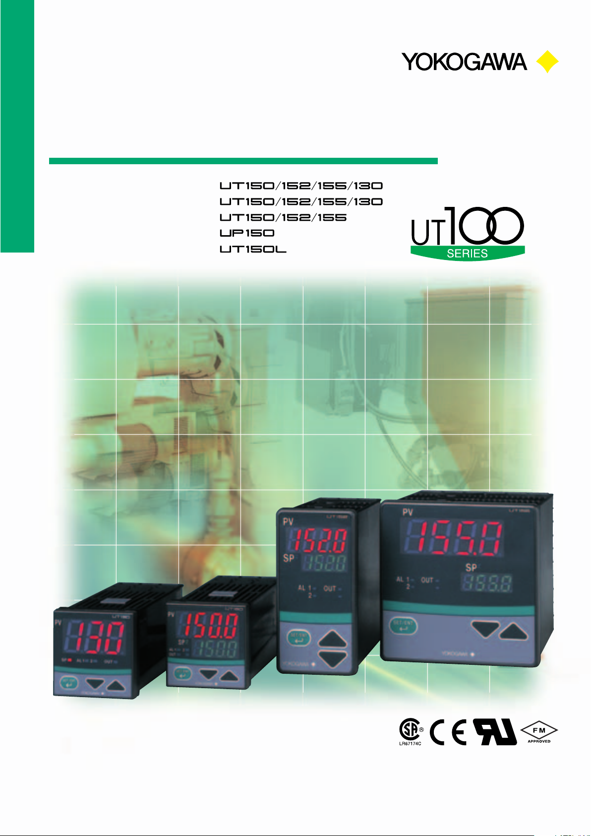
Temperature Controllers
• Indicating Controllers
• Heating & Cooling controllers
• Motorized valve controllers
• Program Controller
• Limit Controller
Bulletin 05C01E01-E
Page 2
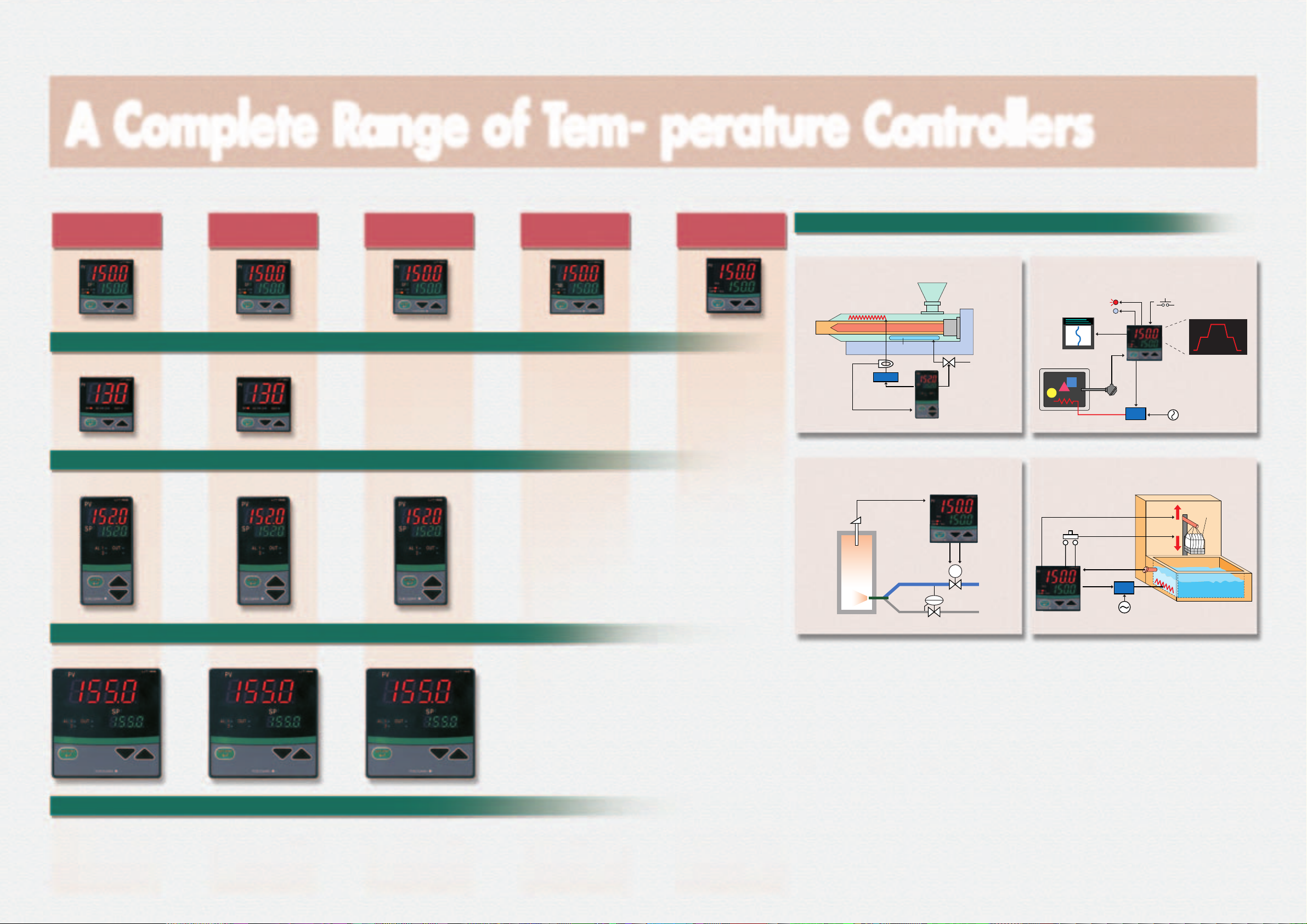
A Complete Range of Tem- perature Controllers
Standard Controllers
ON/OFF, PID
UT150-씲N
UT150 series
UT130-씲N
UT130 series
UT152-씲N
UT152 series
Heating & Cooling
Controllers
UT150-씲씲 UT150-RR/Z UT150L UP150
1/16DIN(48*48)
UT130-씲씲
1/16DIN(48*48)
UT152-씲씲 UT152-RR/Z
1/8DIN(48*96)
Motorized Valve
Controllers
Limit
Controller
Program
Controller
Typical Applications
앬
Heating & Cooling Control
Injection Molding Machine
Heater
Cooling water
CT
SSR
Voltage pulse
(for heating side)
Heater disconnection alarm
앬
Motorized Valve Drive Control앬 PID control with Timer function
Cooling
water
Relay output
(for cooling side)
UT152/155
Small Furnace
TC or RTD
UT150-RR/Z
M
Air
Gas
앬
Program Control
Simple Ceramic Oven
Alarm Output PLC or Switch
Recorder
UP150
4 to 20 mA DC
TC
SCR
Temperature Profile
Cleaning Machine for Precision Parts
Stop
cleaning
TMR
Temperature
4 to 20 mA
cleaning
Start
SCR
(Raise)
(Lower)
Heater
Cleaning tank
Time-up signal
Switch
UT150
Parts
UT155-씲N
UT155 series
2 3
1/4DIN(96*96)
UT155-씲씲 UT155-RR/Z
Page 3

Simple design, All the necessary functions
UP150 Temperature Program Controller
Function Block Diagram
Functional block diagram for Heating & Cooling type UT150/152/155 controller.
Heater Current
Detection Input (/HBA)
Timer ON signal
For Heater
Disconnection Alarm
Outputs
AL2
AL1
CT
(/AL or /HBA)
Pre-set Output
PV Output
4 to 20mA
PV Retransmission
Output (/RET)
Contact Inputs (/EX)
PV Input
Bias & Filtering
SP selection
SP2SP1
Rate-of-change
Limiter
PID Control
STOP
RUN
Heating Output
Relay contact, Voltage Puse or 4 - 20mA
for each output
STOP/RUN
SUPER &
Dynamic AT
Cooling Output
DI1
Functions Selector
switching
DI2
Alarm & Timer
SUPER Function
SUPER control function suppresses
overshooting. The field-proven SUPER
function utilizes build-in operator experience
and Fuzzy theory to deliver fine cotrol and
suppress overshooting.
Dynamic AT is started
when SP is changed.
Temperature
Temperature
Time
Conventional PID control
UT100 control with SUPER
RUN/STOP function
The control output is switched to Pre-set MV
during STOP mode. RUN/STOP mode is
selected by digital input. Pre-set MV can be
set as 0% or 100%. In case of Heating &
Cooling control, both Pre-set outputs are 0%.
Other Optional Functions
•SP switching:
A setpoint can be selected from
two setpoints (SP1, SP2).
•PV Retransmission output:
PV signal is output as a 4 to 20mA signal
•24V power supply:
24V AC/DC power supply is also available.
Communication Function
Three protocols are available on RS485 communication port:
MODBUS( RTU, ASCII )
Yokogawa PC-link
Yokogawa Ladder communication
Number of controllers: Up to 31
Max. distance: 1,200m
Baud rate: 2400, 4800, or 9600 bps
Personal computer, or PLC
RS232C/RS485 converter
Max. 1200 m; up to 31 slave controllers can be connected
UT150 controllers
Keys and Displays
1
2
3
4
7
Alarm Functions
25 types of Alarms are available.
De-energized type and Waiting action are
available.
PV alarms: Low, High,
Deviation alarms: Low, High, Low & High
Heater Disconnection alarm
Self check alarms: Fail, Error
Timer Function
Timer function is used to count the heating
time for simple oven.
Output status changes when the preset time
has passed since a contact input turned on.
Time
PV
SP
Active or Passive function is available.
Max. time span: 99min. 59sec.
Start/Stop: One Digital Input
Two outputs from above alarms and
a timer can be output.
1
SP2:
"2" is illuminated when SP2
(Set point 2) is selected.
AL1,AL2: Red
2
Illuminates when Alarm
5
6
is activated.
OUT: Red
3
Illuminates when Output is ON.
SET/ENT key:
4
Enter the setting data.
Press 3sec to parameter
setting.
5
PV display: (Red)
6
SP display: (Green)
: data increase key
7
: data decrease key
High & Low within deviation
PLC
Model UP150 is a simple program controller. UP150 is applicable to temperature program control for small oven, ceramic kilns, drying oven and
sterilizer etc.
PV Output
4 to 20mA
PV Retransmission
Output (/RET)
PV Input
Bias & Filtering
PID Control
Output
Relay contact,
Voltage Puse or 4 - 20mA
Contact Inputs (/EX)
DI1
Run/Reset
switching
Program Setpoint
SUPER & AT
PV & Time
Events
DI2
Hold/Re-start
switching
EV2EV1
SEG lamp
1
Illuminates when the segment no. or remaining
segment time is displayed on SP display.
2
EV1, EV2 lamps
RUN lamp
3
Illuminates while the operation mode is “RUN”.
6
Flashing while the operation mode is “WAIT”.
1
2
3
4
5
8
9
HLD (hold) lamp
4
Illuminates while the operation mode is “HOLD”.
7
SET/ENT key
5
PV display
6
Indicates PV
SP display
7
Indicates SP (setpoint), segment no., remaining
segment time and parameter values.
Run key (or Data change key)
8
Start (RUN) the program control.
Reset key (or Data change key)
9
Stop (RESET) the program control.
Temperature Program
Up to 16 segments
Time Event Output
Start Max. 1,599 hours
UT150L Limit Controller
The UT150L Limit Controller (1/16 DIN size) is a FM approved
instrument that can be configured either as a high limit or a low limit
controller by a user. The UT150L features universal input, a timer to
count the duration time if the setpoint is exceeded, and a register to
retain the maximum temperature reached. The two alarm outputs,
retransmission output, and communication function are available as
optional features.
• High Limit action
SP
Control
Output
Open
Output can not be reset
when PV comes back
to normal condition.
PV
hysteresis
Close
Press RESET key
to reset the output
•Specifications for Program function
Number of program pattern: One
Number of program segments: 16 segments
Program time span: Up to 1,599hours
Accuracy of program time span: +/-2% of span
Program operations: Wait, Hold, Advance
Event outputs(standard feature): Two contact outputs
Two contact inputs(option): For Run / Reset switching
For Hold / Restart (Cancel Hold)
switching
UT150/Z Motorized Valve Controller
Model UT150/Z has two relay contact outputs to control a motorized
valve or a motorized actuator. Model UT150/Z does not need the
valve position feedback signal. This controller estimates the valve
position automatically.
UT150/Z has MAN mode for moving the valve position manually.
Non-linear control function is available to prolong the valve life.
Function Block Diagram for Motorized Valve Controllers
Contact Inputs (/EX)
DI1
SP2SP1
Functions Selector
SP selection
Manual
DI2
Timer ON
signal
(/AL)
Alarm & Timer
Outputs
AL2AL1
Bias & Filtering
Pre-set Output
Estimated
valve position
Reverse MV
Relay Contact Outputs
PV Input
Rate-of-change
Limiter
PID Control AT
AUTO/MAN
STOP/RUN Switching
Comparator
Direct MV
4 5
Page 4

24V AC/DC
Terminal Arrangements
UT130
Alarm Outputs
11
ALM2
12
ALM1
13
COM
Option "/AL" or "/HBA"
Heater Current
Detection Input
1
2
Option "/HBA"
For Standard type
Cooling-side Control Output
(for heating/cooling type only)
1
CT
Relay Contact
2
Heater Current
Detection Input
3
CT
4
5
Option "/HBA"
For Heating/Cooling type
NO
COM
+
Voltage Pulse
--
RS-485
3
4
5
Option "/RS"
RSB(+)
RSA(-)
SG
Specification Table
UT130
PV/SP Data display
PV Input
Accuracy
3 digits
1 Universal(TCs, RTDs)
1Co 1digit for RTDs, 2Co 1digit for TCs(except for B, R, S and under 0Co), 0.3% 1digit for mV and V
Control scan period
Number of Setpoints(SP)
Setpoint Program pattern
Segment of program pattern
Control type
Super, Auto Tuning
Control Output
6
7
8
PV Input
B
b
A
RTD
+
--
TC
Control Output for Cooling output
1
2
3
4
5
6
11
7
12
8
13
9
14
10
15
Power Supply
L
9
10
N
100-240V AC
+
24V AC/DC
24V AC/DC
--
Option /24V
PV retransmission output
Contact Input
Timer
Alarm
Heater disconnection alarm
Two contact outputs
Communication
1
ON/OFF, PID
SUPER, Dynamic AT
Relay or Voltage Pulse
Relay or Voltage Pulse
N/A
N/A
N/A
1 point
Alarm, Heater disconnection
Power supply
Control Output
(heating output for heating/cooling)
NO
14
Relay Contact
15
COM
+
Voltage Pulse
--
Approvals
Front Face protection
Size, (Hight* Width* Depth mm)
Ambient T emperature, R.H.
IP65
48*48*100mm
0 to 50C
UT150, UT152, UT155
N/A(Not Available)
N/A
ON/OFF, PID
Relay, Voltage Pulse or 4-20mA
Relay, Voltage Pulse or 4-20mA
1 point, 4-20mA
2 points for SP selection, RUN/STOP switching or Timer
25 types
1 point
Alarm, Heater disconnection or Timer
100-240Vac(8VA), 24Vac/dc(3W)
IP65 for UT150, IP55 for UT152/155
UT150 = 48*48*100mm
UT152 = 96*48*100mm
o
, 20 to 90%(non condensing) For strage conditions -25 to 70Co 5 to 95%(non condensing)
UT155 = 96*96*100mm
(Visit our WEB site for more information http;//www.yokogwa.com/MCC/)
Motorized Valve control
UT150, UT152, UT155
Program Control
UP150
Limit Control
4 digits / 4 digits
1 Universal(TCs, RTDs, mV, V)
500ms
2
Position Prop. PID
AT
Two Relays
N/A
N/A
Up to 99hours 59min.
N/A
N/A
1
16
ON/OFF, PID
SUPER, AT
Relay, Voltage Pulse or 4-20mA
N/A
2 points for Program operation
N/A
PV and Time events
N/A
PV & Time events
1
N/A
N/A
Limit Control
N/A
Relay
N/A
1 point, 4-20mA
1 point for Reset
N/A
22 types
N/A
Alarms
RS485, Protocol(MODBUS, PC-link, Ladder)
100-240Vac(8VA)
UL, CE, CSA
IP65
FM, UL, CE, CSA
IP65
48*48*100mm
UT150L
UT150, UT150-RR/Z, UT150L, UP150
Alarm or Event outputs
11
ALM2, EV2
12
ALM1, EV1
13
NO
1
Relay
Contact
COM
2
Contact Inputs
DI 2
3
DI 1
4
COM
5
+
--
COM
Voltage
Pulse
+
4-20mA
--
Retransmission
Output
Option "/RET"
Heater Current
Detection Input
3
4
Option "/HBA"
For Standard type with "/RET"
For Heating/Cooling type
+
1
2
--
CT
Heater Current
Detection Input
For Standard type
Option "/RS"
Option "/AL" or "/HBA"
Standard for UP150
Option "/HBA"
1
CT
2
RS-485
3
RSB(+)
4
RSA(-)
5
SG
Second Control Output
Cooling-side output
for heating/cooling type.
Reverse Rotation output
for position prop. PID.
Option "/EX"
Standard for UP150
DI1 is available for UT150L
UT152/155, UT152/155-RR/Z
The terminal arrangements of
the UT152 and UT155 are
the same.
Retransmission
Output
Option "/RET"
+
1
--
2
Option "/EX"
External Contact Inputs
DI 1
21
DI 2
22
COM
23
+
--
Voltage
Pulse
Heater Current
Detection Input
24
CT
25
Option "/HBA"
+
4-20mA
--
Option "/RS"
RS-485
26
RSB(+)
27
RSA(-)
28
SG
Second Control Output
Cooling-side output
for heating/cooling type.
Reverse Rotation output
for position prop. PID.
NO
1
Relay
Contact
COM
2
PV input Type and Ranges(key selectable)
앬 UT130 Input Ranges 앬
PV Input
6
B
+
7
b
8
A
RTD
+
--
--
Voltage
TC
Thermocouple
K
J
T
1
2
3
4
5
6
11
7
12
8
13
9
14
10
15
1121
12
22
23
13
14
24
25
15
16
26
17
27
28
18
29
19
30
20
Power Supply
L
9
10
100-240V AC
Control Output
Heating output for heating/cooling
Direct rotation for position prop. PID
14
15
N
Relay
Contact
NO
COM
+
24V AC/DC
24V AC/DC
--
Option /24V
+
Voltage
Pulse
--
+
4 - 20mA
--
PV Input
6
B
+
--
TC
+
--
Option /24V
+
Voltage
Pulse
--
24V AC/DC
24V AC/DC
+
--
Voltage
+
4 - 20mA
--
Option "/AL" or "/HBA"
7
b
8
A
RTD
Control Output
(heating output for heating/cooling)
NO
14
Relay
Contact
COM
15
Power Supply
L
19
20
N
100-240V AC
Alarm Outputs
16
ALM2
17
ALM1
18
COM
RTD
Panel Cutout Dimensions
앬 UT130 and UT150 앬 UT152 앬 UT155
General
Mounting
Side-by-side
Close Mounting
N is the number of controllers.
If N≥5, then measure the actual length.
E
L
U
Pt100
JPt100
Min. 70
0.6
+
0
45
-199 to 999˚C
-199 to 200˚C
-199 to 999˚C
-199 to 400˚C
-199 to 999˚C
-199 to 900˚C
-199 to 400˚C
-199 to 850˚C
-199 to 200˚C
-19.9 to 99.9˚C
-199 to 500˚C
Min. 70
+
0.6
(25)
45
0
{(N-1)×48+45}
0 to 600˚C
0 to 400˚C
0 to 400˚C
Unit: mm Unit: mm Unit: mm
(25)
0.6
0
+
45
+
0.6
0
Range(°F)Range(°C)Input Type
-199 to 999˚F
32 to 999˚F
32 to 750˚F
-199 to 400˚F
-199 to 999˚F
-199 to 750˚F
-199 to 999˚F
-199 to 999˚F
-199 to 750˚F
-199 to 999˚F
32 to 750˚F
-199 to 400˚F
-199 to 999˚F
General
Mounting
Side-by-side
Close Mounting
0
0.8
+
N is the number of controllers.
If N ≥ 5, then measure the actual length.
92
UT150/152/155/150L and UP150 Input Ranges
Range(°C) Range(°F)Input Type
-270 to1370˚C
0.0 to600.0˚C
0.0 to400.0˚C
-199.9 to200.0˚C
-199.9 to999.9˚C
-199.9 to400.0˚C
-199.9 to999.9˚C
0to1700˚C
0to1700˚C
0to1800˚C
-200 to1300˚C
-199.9 to900.0˚C
-199.9 to400.0˚C
0to1390˚C
-199.9 to850.0˚C
0.0 to400.0˚C
-199.9 to200.0˚C
-19.9 to99.9˚C
-199.9 to500.0˚C
0.0 to100.0
0.000 to5.000
1.000 to5.000
0.00 to10.00
Min. 145
(25)
0
0.8
+
N is the number of controllers.
If N ≥ 5, then measure the actual length.
92
Min. 145
Thermocouple
DC voltage
Min. 70
+
45
(25)
{(N-1)×48+92}
K
J
T
E
R
S
B
N
L
U
Platinel 2
RTD
Pt100
JPt100
0 to100mV
0 to 5 V
1 to 5 V
0 to 10 V
General
Mounting
(53)
0
0.8
+
92
0.6
0
+
0.6
0
Side-by-side
Close Mounting
-300 to 2500˚F
32.0 to 999.9˚F
32.0 to 750.0˚F
-300.0 to 400.0˚F
-300 to 2100˚F
-300.0 to 750.0˚F
-300.0 to 1800.0˚F
32.0 to 3100˚F
32.0 to 3100˚F
32.0 to 3200˚F
-300 to 2400˚F
-300 to 1600˚F
-300 to 750˚F
32.0 to 2500˚F
-199.9 to 999.9˚F
32.0 to 750.0˚F
-300 to 400˚F
-199.9 to 999.9˚F
Min. 117
+
0.8
92
0
{(N-1)×96+92}
(53)
0
0.8
+
92
+
0.8
0
6 7
Page 5

Model & Suffix codes
Note:
1. One optional function can be selected from each option group A and B. Other optional functions can be selected freely.
2. /HBA option includes all functions that /AL option has. /AL and /HBA can not be selected at same time.
앬
Model UT130 Standard Controller
Model
UT130
Control Output
Options
앬
Model UT150 Standard Controller
Model
UT150
Control Output
Options
앬
Model UT152/155 Standard Controllers
Model
UT152
UT155
Control Output
Options
앬
Model UT150 Motorized Valve Controller
Model
UT150
Control Output
Options
앬
Model UT152/155 Motorized Valve Controllers
Model
UT152
UT155
Control Output
Options
-RN
-VN
-RN
-VN
-AN
group A
group B
-RN
-VN
-AN
-RR
group A
-RR
Suffix Code
/AL
/V24
/HBA
/RS
Suffix Code
/AL
/V24
/HBA
/RET
/EX
/RS
Suffix Code
/AL
/V24
/HBA
/RET
/EX
/RS
Suffix Code
/AL
/V24
/EX
/RS
Suffix Code
/AL
/V24
/EX
/RS
Controller 1/16DIN
Relay contact output
Voltage Pulse output
Alarm outputs (2 points)
Power supply 24Vac/dc
Heater disconnection alarm
Communication function
Controller 1/16DIN
Relay contact output
Voltage Pulse output
4-20mA output
Alarm outputs (2 points)
Power supply 24Vac/dc
Heater disconnection alarm
PV retransmission output
Two contact inputs
Communication function
Controller 1/8 DIN
Controller 1/4 DIN
Relay contact output
Voltage Pulse output
4-20mA output
Alarm outputs (2 points)
Power supply 24Vac/dc
Heater disconnection alarm
PV retransmission output
Two contact inputs
Communication function
Controller 1/16DIN
Relay contact outputs
Alarm outputs (2 points)
Power supply 24Vac/dc
Two contact inputs
Communication function
Position Proportional PID
/Z
Controller 1/8DIN
Controller 1/8DIN
Relay contact outputs
Alarm outputs (2 points)
Power supply 24Vac/dc
Two contact inputs
Communication function
Position Proportional PID
/Z
Description
Description
Description
Description
Description
앬
Model UT130 Heating & Cooling Controller
Model
UT130
Heating Output
Cooling Output
Options
앬
Model UT150 Heating & Cooling Controller
Model
UT150
Heating Output
Cooling Output
Options
* HBA can not be selected when the heating control output is 4-20mA
앬
Model UT152/155 Heating & Cooling Controllers
Model
UT152
UT155
Heating Output
Cooling Output
Options
* HBA can not be selected when the heating control output is 4-20mA
앬
Model UP150 Program Controller
Model
UP150
ControlOutput
Options
앬
Model UT150L Limit Controller
Model
UT150L
Control Output
Options
-R
-V
-R
-V
-A*
-R
-V
-A*
-RN
-VN
-AN
group A
-RN
Suffix Code
R
V
group A
Suffix Code
R
V
A
group A
Suffix Code
R
V
A
Suffix Code
/V24
/RET
/EX
/RS
Suffix Code
/AL
/RET
/EX
/RS
/AL
/V24
/HBA
/RS
/AL
/V24
/HBA*
/EX
/RS
/AL
/V24
/HBA*
/EX
/RS
Controller 1/16DIN
Description
Relay contact output
Voltage Pulse output
Relay contact output
Voltage Pulse output
Alarm outputs (2 points)
Power supply 24Vac/dc
Heater disconnection alarm
Communication function
Description
Controller 1/16DIN
Relay contact output
Voltage Pulse output
4-20mA output
Relay contact output
Voltage Pulse output
4-20mA output
Alarm outputs (2 points)
Power supply 24Vac/dc
Heater disconnection alarm
Two contact inputs
Communication function
Description
Controller 1/8DIN
Controller 1/8DIN
Relay contact output
Voltage Pulse output
4-20mA output
Relay contact output
Voltage Pulse output
4-20mA output
Alarm outputs (2 points)
Power supply 24Vac/dc
Heater disconnection alarm
Two contact inputs
Communication function
Description
Program Controller 1/16DIN
Relay contact output
Voltage Pulse output
4-20mA output
Power supply 24Vac/dc
PV retransmission output
Two contact inputs
Communication function
Description
Limit Controller 1/16DIN
Relay contact output
Alarm outputs (2 points)
PV retransmission output
One contact input
Communication function
YOKOGAWA ELECTRIC CORPORATION
Network Solutions Business Div.
/Phone: (81)-422-52-7179, Fax: (81)-422-52-6793
E-mail: tm@csv.yokogawa.co.jp
YOKOGAWA CORPORATION OF AMERICA Phone: (1)-770-253-7000, Fax: (1)-770-251-2088
YOKOGAWA EUROPE B.V. Phone: (31)-33-4641806, Fax: (31)-33-4641807
YOKOGAWA ENGINEERING ASIA PTE. LTD. Phone: (65)-62419933, Fax: (65)-62412606
Subject to change without notice.
[Ed : 07/b] Copyright ©2001
Printed in Japan, 506(KP)
RS-14E
 Loading...