

Page 1

User ’s
Manual
Model UPM100, UPM101
Universal Power Monitor
Communication Functions
Yokogawa Electric Corporation
IM 77C01H01-10EN
4th Edition
Page 2

Page 3

Introduction
This user’s manual describes the communication functions of the UPM100 and UPM101
universal power monitors and contains information on how to create communication
programs.
Read the manual carefully to understand the communication functions of the UPM100 and
UPM101 universal power monitors.
In this manual, “UPM100 and UPM101 universal power monitors” are referred to as
“UPM100 universal power monitor” because the communication functions of UPM100
and UPM101 universal power monitors are common.
And the illustrations of “UPM100 universal power monitor with display function” are used
for description.
The UPM100 universal power monitor has the following communication protocols.
• PC link communication protocol
• MODBUS communication protocol
• UPM01 communication protocol
1
You are required to have background knowledge of the communication specifications
of higher-level devices, their communication hardware, language used for creating
communication programs, and so on.
1: The UPM01 communication protocol is the original communication protocol for the UPM01,
UPM02, and UPM03. The protocol can be used only for the UPM100 universal power monitor
with the optional measuring function “Integral resolution Wh” specified at ordering.
Intended Readers
This manual is intended for people familiar with the functions of the UPM100 universal
power monitor, control engineers and personnel in charge of maintaining instrumentation
and control equipment.
Related Documents
The following user’s manuals all relate to the communication functions of the UPM100
universal power monitor. Read them as necessary.
• Model UPM100 Universal Power Monitor User’s Manual
Document number: IM 77C01H01-00EN
• Model UPM100 Universal Power Monitor User’s Manual
(for 920 MHz Wireless Communication model)
Document number: IM 77C01H01-43EN
Note: 920 MHz wireless communication can be used only in the Republic of Korea.
• Model UPM101 Universal Power Monitor (With Dedicated CT) User’s Manual
Document number: IM 77C01J01-00EN
4th Edition: Mar. 8
All Rights Reserved, Copyright © 2005, Yokogawa Electric Corporation
IM 77C01H01-10EN
i
Page 4

Documentation Conventions
Symbols
This manual uses the following symbols.
Symbols Used in the Main Text
Markings
See Also Gives reference locations for further information on the topic.
Symbols Used in Figures and Tables
Markings
[See Also] Gives reference locations for further information on the topic.
Note Draws attention to information that is essential for understanding
the operation and/or features of the product.
TIP Gives additional information to complement the present topic.
[NOTE] Draws attention to information that is essential for understanding
the features of the product.
[TIP] Gives additional information to complement the present topic.
Description of Displays
1. Some of the representations of product displays shown in this manual may be
exaggerated, simplified, or partially omitted for reasons of convenience when explaining
them.
2. Figures and illustrations representing the universal power monitor’s displays may differ
from the real displays in regard to the position and/or indicated characters (uppercase or lower-case, for example), the extent of difference does not impair a correct
understanding of the functions and the proper operations and monitoring of the system.
ii
IM 77C01H01-10EN
Page 5

Notices
Regarding This User’s Manual
1. This manual should be passed on to the end user. Keep the manual in a safe place.
2. Read this manual carefully to gain a thorough understanding of how to operate this
product before you start using it.
3. This manual is intended to describe the functions of this product. Yokogawa Electric
Corporation (hereinafter simply referred to as Yokogawa) does not guarantee that these
functions are suited to the particular purpose of the user.
4. Under absolutely no circumstance may the contents of this manual, in part or in whole,
be transcribed or copied without permission.
5. The contents of this manual are subject to change without prior notice.
6. Every effort has been made to ensure accuracy in the preparation of this manual.
Should any errors or omissions come to your attention however, please contact your
nearest Yokogawa representative or our sales office.
Regarding Protection, Safety, and Prohibition Against Unauthorized Modification
1. In order to protect the product and the system controlled by it against damage and
ensure its safe use, be certain to strictly adhere to all of the instructions and precautions
relating to safety contained in this document. Yokogawa does not guarantee safety if
products are not handled according to these instructions.
2. The following safety symbols are used on the product and/or in this manual.
Symbols Used on the Product and in This Manual
Markings
This symbol on the product indicates that the operator must refer
to an explanation in the user’s manual in order to avoid the risk
of injury or death of personnel or damage to the instrument. The
manual describes how the operator should exercise special care
to avoid electric shock or other dangers that may result in injury or
loss of life.
Protective
Grounding
Terminal
This symbol indicates that the terminal must be connected to
ground prior to operating the equipment.
IM 77C01H01-10EN
iii
Page 6

Force Majeure
1. Yokogawa does not make any warranties regarding the product except those mentioned
in the WARRANTY that is provided separately.
2. Yokogawa assumes no liability to any party for any loss or damage, direct or indirect,
caused by the use or any unpredictable defect of the product.
3. Be sure to use the spare parts approved by Yokogawa when replacing parts or
consumables.
4. Modification of the product is strictly prohibited.
5. Reverse engineering such as the disassembly or decompilation of software is strictly
prohibited.
6. No portion of the software supplied by Yokogawa may be transferred, exchanged,
leased, or sublet for use by any third party without the prior permission of Yokogawa.
iv
IM 77C01H01-10EN
Page 7

Contents
Introduction ................................................................................................................................................ i
Documentation Conventions .................................................................................................................... ii
Notices ..................................................................................................................................................iii
Chapter 1 Setup
1.1 Setup Procedure .................................................................................................................1-1
1.2 Notes on Setting RS-485 Communication Conditions ........................................................1-2
Chapter 2 RS-485 Communication Specifications
Chapter 3 Procedures for Setting UPM100/UPM101 Functions
3.1 Basic Setting .......................................................................................................................3-2
3.1.1 Setting of VT Ratio .................................................................................................................3-2
3.1.2 Setting of CT Ratio .................................................................................................................3-3
3.1.3 Setting of Integral Low-cut Power ..........................................................................................3-4
3.2 Setting Pulse Output ...........................................................................................................3-5
3.2.1 Pulse Unit-1 of Electric Energy ..............................................................................................3-5
3.2.2 ON Pulse Width-1 of Electric Energy .....................................................................................3-6
3.2.3 Pulse Unit-2 of Electric Energy ..............................................................................................3-7
3.2.4 LAG/LEAD/Regenerative Selection for Pulse Output of Electric Energy ...............................3-8
3.2.5 ON Pulse Width-2 of Electric Energy .....................................................................................3-9
3.3 Executing Reset Operations .............................................................................................3-10
3.3.1 Remote Reset ......................................................................................................................3-10
3.3.2 Active Energy Reset ............................................................................................................. 3-11
3.3.3 Maximum/Minimum Values Reset ........................................................................................ 3-11
3.3.4 Regenerative Energy Reset .................................................................................................3-12
3.3.5 Reactive Energy Reset ........................................................................................................3-12
3.3.6 Apparent Energy Reset ........................................................................................................3-13
3.4 Other Settings ...................................................................................................................3-14
3.4.1 Start of Optional Integration .................................................................................................3-14
3.4.2 Stop of Optional Integration .................................................................................................3-14
3.4.3 Start/Stop of Integration .......................................................................................................3-15
3.4.4 Active Energy Writing ...........................................................................................................3-16
3.4.5 Apparent Energy Writing ......................................................................................................3-17
3.4.6 LEAD Reactive Energy Writing ............................................................................................3-18
3.4.7 LAG Reactive Energy Writing ..............................................................................................3-19
3.4.8 Regenerative Energy Writing ...............................................................................................3-20
1
2
3
4
5
6
7
8
App
Chapter 4 PC Link Communication
4.1 Overview .............................................................................................................................4-1
4.1.1 Configuration of Command ....................................................................................................4-2
4.1.2 Configuration of Response .....................................................................................................4-3
4.1.3 Response Error Codes ...........................................................................................................4-4
4.1.4 Specifying Broadcast .............................................................................................................4-5
4.2 Command and Response ...................................................................................................4-6
BRD Reads I relays on a bit-by-bit basis ...............................................................................................4-7
BWR Writes data into I relays on a bit-by-bit basis ...............................................................................4-8
BRR Reads I relays on a bit-by-bit basis in a random order .................................................................4-9
BRW Writes data into I relays on a bit-by-bit basis in a random order ................................................4-10
BRS Specifies I relays to be monitored on a bit-by-bit basis ............................................................... 4-11
BRM Monitors I relays on a bit-by-bit basis .........................................................................................4-12
WRD Reads D registers and I relays on a word-by-word basis ..........................................................4-13
WWR Writes data into D registers and I relays on a word-by-word basis ...........................................4-14
WRR Reads D registers and I relays on a word-by-word basis in random order ................................ 4-15
WRW Writes data into D registers and I relays on a word-by-word basis in random order .................4-16
WRS Specifies the D registers and I relays to be monitored on a word-by-word basis ......................4-17
WRM Monitors the D register and I relays on a word-by-word basis ..................................................4-18
INF6 Reads the model, suffix codes, and version information ............................................................4-19
INF7 Reads the maximum value of CPU.............................................................................................4-20
IM 77C01H01-10EN
v
Page 8

Contents
4.3 Communication with Higher-level Devices ........................................................................ 4-21
4.3.1 Communication with FA-M3 (UT Link Module) .....................................................................4-21
4.3.2 Communication with Touch Panel ........................................................................................ 4-23
Chapter 5 MODBUS Communication
5.1 Overview .............................................................................................................................5-1
5.2 Message and Response ...................................................................................................5-10
5.1.1 Configuration of Message ......................................................................................................5-3
5.1.2 Specifying D Registers ...........................................................................................................5-4
5.1.3 Checking Errors .....................................................................................................................5-4
5.1.4 Responses from Slaves .........................................................................................................5-7
5.1.5 Specifying Broadcast .............................................................................................................5-9
03 Reads data from multiple D registers ............................................................................................. 5-11
06 Writes data into D register ..............................................................................................................5-12
08 Performs loop back test ..................................................................................................................5-13
16 Writes data into multiple D registers ...............................................................................................5-14
Chapter 6 Functions and Usage of D Registers
6.1 Overview of D Registers .....................................................................................................6-1
6.2 Interpretation of D Register Map Table ...............................................................................6-2
6.3 Configuration of D Registers ............................................................................................... 6-3
6.4 D Register Map ...................................................................................................................6-4
Chapter 7 Functions and Usage of I Relays
7.1 Configuration of I Relays ..................................................................................................... 7-2
7.2 I Relay Map ......................................................................................................................... 7-3
Chapter 8 UPM01 Communication (Original Communication Protocol)
8.1 Overview .............................................................................................................................8-1
8.2 Frame Configuration ...........................................................................................................8-2
8.3 Functions ............................................................................................................................. 8-5
8.3.1 Measured Items (Category A) ................................................................................................8-5
8.3.2 Statistical Items (Category B) .................................................................................................8-7
8.3.3 Set Items (Category C) ..........................................................................................................8-8
8.3.4 User Control Items (Category E) ..........................................................................................8-10
Appendix
Appendix 1 Table of ASCII Codes (Alphanumeric Codes) .................................................................App-1
Revision Information
vi
IM 77C01H01-10EN
Page 9

010101E.EPS
Chapter 1 Setup
1 Setup
This chapter describes the setup procedure required to use the communication functions
and the communication specifications of the UPM100 universal power monitor.
Hereafter, the UPM100 universal power monitor is simply referred to as the UPM100.
1.1 Setup Procedure
Set up the communication functions on the UPM100 as follows:
Set up the communication function parameters of the UPM100.
For the UPM100 with display function, set up the communication conditions using the
front panel keys.
For the UPM100 without display function, set up the communication conditions using
the front DIP switches. (See the user's manual of Model UPM100 Power Monitor
<Initial Setup Operations>.)
Connect a higher-level device and a UPM100.
(See the user's manual of Model UPM100 Power Monitor <Installation>.)
1
Setup
Create communication programs for the higher-level device to perform communication.
(See "4. PC Link Commnication" or "5. MODBUS Communication" for the communication
protocol. See "6. Functions and Usage of D Registers", "7. Functions and Usage of I
Relays" and "8. UPM01 Communication" for the data storing.)
To avoid an electric shock, be sure to turn off the power supply source to the
equipment involved before you start wiring.
Note
• In the case of PLC (MELSEC:Mitsubishi Electric Corporation’s sequencer), “B” is for (-), and “A”
is for (+).
• Do not share the grounding wire with another instrument. Doing so may result in a failure of the
instrument. Use crimp terminals at cable ends.
Note Create communication programs referring to the documentation of each higher-level device.
Higher-level devices : PCs, PLCs (sequencers), touch panels, and others.
IM 77C01H01-10EN
1-1
Page 10
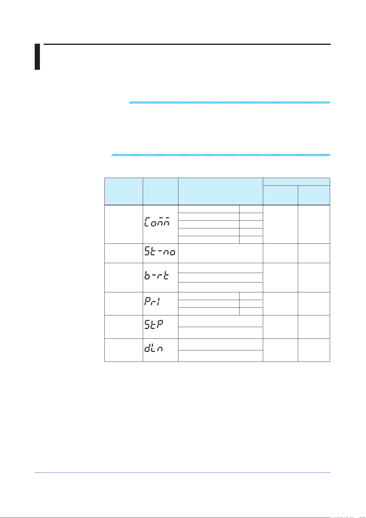
1.2 Notes on Setting RS-485 Communication Conditions
This section describes the setting parameters for using the communication functions
and their setting ranges.
Note
The details of the UPM100 communication conditions need to be the same as those of the
communication conditions of the higher-level device to be connected.
• UPM100 without display function (UPM100-xx0xx-20 or UPM100-xx2xx-20): Set up
the communication conditions using the front DIP switches. (See the user’s manual of Model
UPM100 Universal Power Monitor <Initial Setup Operations>.)
• UPM100 with display function (UPM100-xx1xx-20 or UPM100-xx3xx-20): Set up
the communication parameters using the front panel keys. (See the user’s manual of Model
UPM100 Universal Power Monitor <Initial Setup Operations>.)
Table 1-1 Parameters to be Set for Communication Functions
Initial Setting
Parameter
Name
RS-485
communication
protocol
Parameter
Symbol
(COMM)
Setting Range
PC link without checksum PCLK1
PC link with checksum PCLK2
MODBUS (ASCII mode) M ASC
MODBUS (RTU mode) M RTU
UPM01 UPM01
Without 920
MHz Wireless
Communication
PCLK2 M RTU
2
With 920 MHz
Wireless
Communication
3
RS-485
station number
RS-485
communication
baud rate
(ST-NO)
(B-RT)
1 to 99 (1 to 31 recommended) 1 1
2400 bps
9600 bps
9600 19200
19200 bps
None NONE
Parity
Stop bit
Data length
(PRI)
(STP)
1
(DLN)
Even EVEN
Odd ODD
1
2
7
8
NONE NONE
1 1
8 8
3
3
1: When “MODBUS (ASCII mode)” is selected in protocol selection, select “7” or “8” for the data
length. When “MODBUS (RTU mode)” is selected, select “8.” Otherwise, communication cannot
be achieved.
2: The UPM01 communication is selectable only when the optional measuring function “Integral
resolution Wh” is specified at ordering.
3: When using 920 MHz Wireless Communication, please use the default value above.
Note: 920 MHz wireless communication can be used only in the Republic of Korea.
3
3
1-2
IM 77C01H01-10EN
Page 11
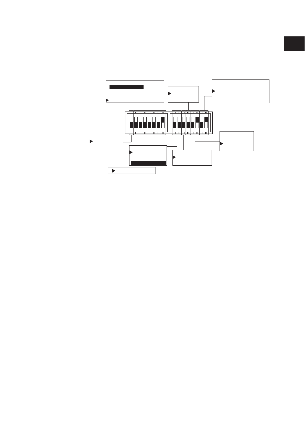
1.2 Notes on Setting RS-485 Communication Conditions
Use the DIP switches to enter the settings on UPM100 without display function.
Referring to the diagram below, set the binary values, with the first bit on the left.
When using 920 MHz Wireless Communication, please use the factory setting values except
for the address.
Note: 920 MHz wireless communication can be used only in the Republic of Korea.
<Address (station number)>
0: Usage prohibited
1 to 99 can be set (1 to 31
recommended)
(Initial setting: 1)
<UPM01 protocol>
0: None
1: With protocol
denotes initial settings.
1
0
<Parity>
00: None
01: Even
10: Odd
11: Usage prohibited
<Data length>
0: 8 bits
1: 7 bits
<Stop bit>
0: 1 bit
1: 2 bits
<Communication protocol>
00: PC link without SUM
01: PC link with SUM
10: MODBUS ASCII
11: MODBUS RTU
<Baud rate>
00: 2400 bps
01: 9600 bps
10: 19200 bps
RS-485 communication protocol (COMM)
Set the communication protocol identical to that of the higher-level device to be connected.
1
Setup
RS-485 communication baud rate (B-RT)
Set the baud rate identical to that of the higher-level device to be connected. (Otherwise,
proper communication cannot be achieved.)
Parity (PRI)
Set the handling of parity to be carried out when data is sent or received. Set the parity bit
state identical to that of the higher-level device to be connected.
Stop bit (STP)
Set the stop bit identical to that of the higher-level device to be connected.
Data length (DLN)
Set the data length identical to that of the higher-level device to be connected. (When
“MODBUS (RTU mode)” is selected in protocol selection, select “8” for the data length.
When “MODBUS (ASCII mode)” is selected, select “7” or “8.”)
RS-485 station number (ST-NO)
Set the station number of the UPM100 itself. A station number of 1 to 99 may be assigned
in any order. However, there is a limitation - the number of UPM100 to be connected to a
single communication port is limited to 31.
When connecting two or more power monitors to a single communication port, make sure
none of the station numbers 1 to 31 is set twice.
IM 77C01H01-10EN
1-3
Page 12
PC
010202E.EPS
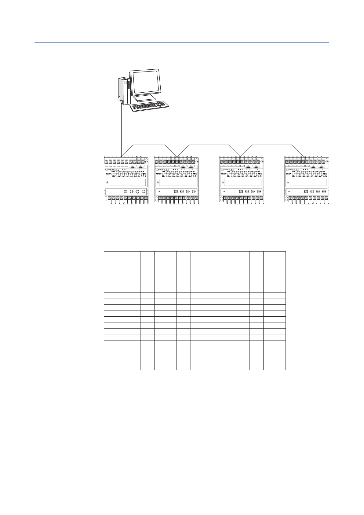
1.2 Notes on Setting RS-485 Communication Conditions
Example of connecting four UPM100 to a higher-level device by setting station numbers of
01, 05, 10, and 20
Maximum overall cable length of 1200 m for a maximum of 31 slave stations
ST-NO=01 ST-NO=05 ST-NO=10 ST-NO=20
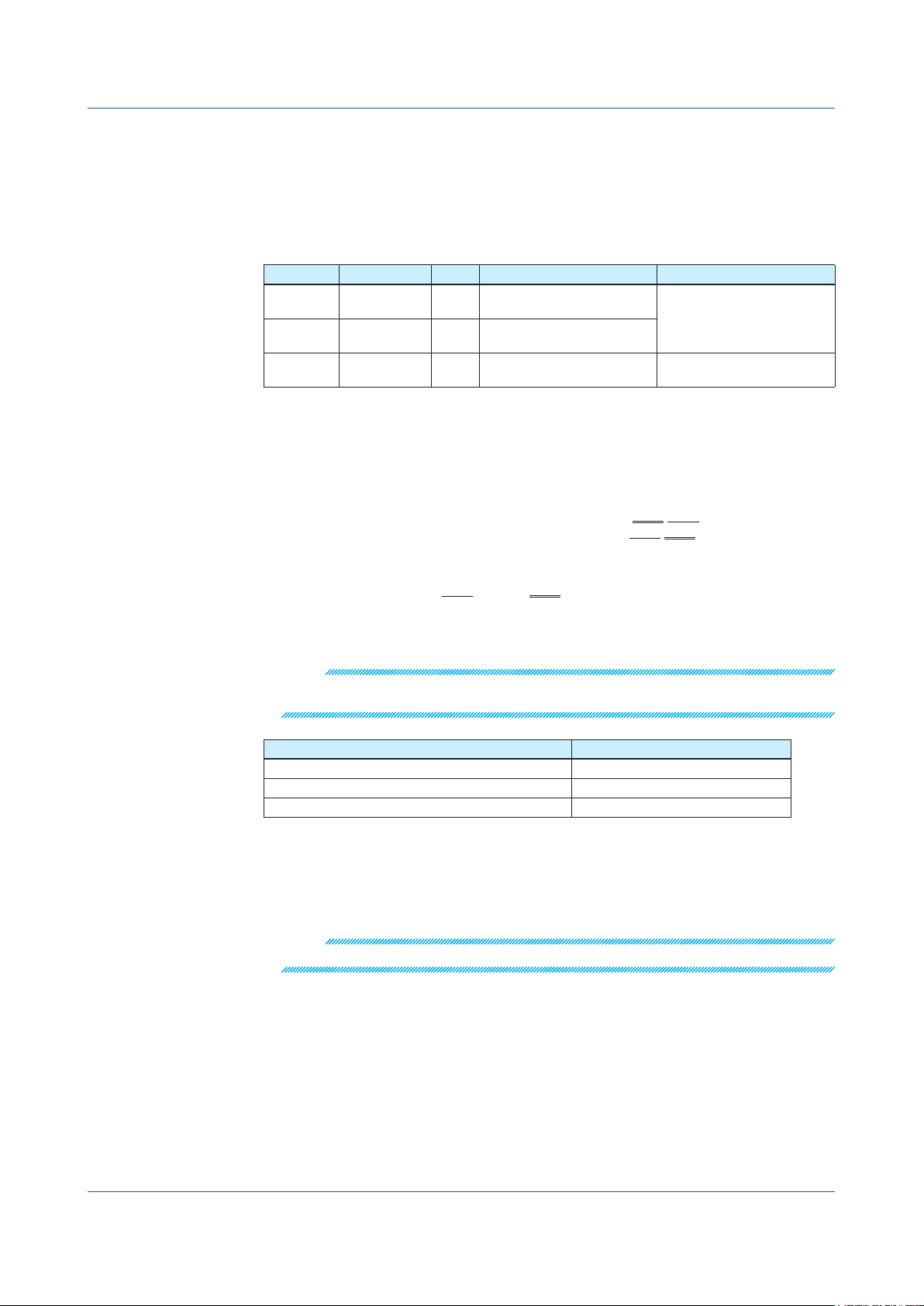
<Binary Number Quick Reference Chart>
The following table is a binary number quick reference chart for use in setting addresses
(station numbers) with DIP switches.
1 0000001 21 0010101 41 0101001 61 01111 01 81 1010001
2 0000010 22 0010110 42 0101010 62 011111 0 82 1010010
3 0000011 23 0010111 43 0101011 63 0 111111 83 1010011
4 0000100 24 0011000 44 0101100 64 1000000 84 1010100
5 0000101 25 0011001 45 0101101 65 1000001 85 1010101
6 0000110 26 0011010 46 0101110 66 1000010 86 1010110
7 0000111 27 0011011 47 01 0 1111 67 1000011 87 1010111
8 0001000 28 0011100 48 0110000 68 1000100 88 1011000
9 0001001 29 0011101 49 0110001 69 1000101 89 1011001
10 0001010 30 0 011110 50 0110010 70 1000110 90 1011010
11 0001011 31 0 0 11111 51 0110011 71 1000111 91 1011011
12 0001100 32 0100000 52 0110100 72 1001000 92 1011100
13 0001101 33 0100001 53 0110101 73 1001001 93 1011101
14 0001110 34 0100010 54 0110110 74 1001010 94 1 0 1111 0
15 0 0 0 1111 35 0100011 55 0 11 0 111 75 1001011 95 10 11111
16 0010000 36 0100100 56 0111000 76 1001100 96 1100000
17 0010001 37 0100101 57 0111001 77 1001101 97 1100001
18 0010010 38 0100110 58 0111010 78 1001110 98 1100010
19 0010011 39 0100111 59 0111011 79 1 001111 99 1100011
20 0010100 40 0101000 60 0111100 80 1010000
1-4
IM 77C01H01-10EN
Page 13

Chapter 2 RS-485 Communication Specifications
2 RS-485 Communication Specifications
The RS-485 communication interface has the PC link communication, MODBUS
communication, and UPM01 communication protocols.
Table 2-1 UPM100 Communication Specifications
Communication Hardware 2-wire RS-485 communication system
PC link communication without checksum
Communication Protocol Specifications
Maximum Baud Rate 19200 bps
Maximun Communication Distance 1200 m
Communication Cable
*1 The UPM01 communication is selectable only when the optional measuring function “Integral
resolution Wh” is specified at ordering.
Table 2-2 Communication Protocols and Types of Devices to be Connected
Communication Protocol Example of Connected Devices
PCs and the like which are installed with a MODBUS communication
MODBUS communication
PC link communication
UPM01 communication
driver and SCADA software.
PLCs which support MODBUS
PCs and the like which are installed with a PC-link communication
driver and SCADA software.
Touch panel (GP series)
PLCs (FA-M3’s UT link module)
PCs and the like which are installed with the PR970 which supports
the UPM01 protocol.
PCs and the like which are installed with SCADA software which
supports the UPM01 protocol.
PC link communication with checksum
MODBUS communication (ASCII mode)
MODBUS communication (RTU mode)
UPM01 communication*1
Shielded twisted-pair cable
(wire size equivalent to AWG24)
2
RS-485 Communication Specifications
Table 2-3 RS-485 Communication Interface
Item Specifications
Standard Conforms to EIA, RS-485
Maximum number of devices to be connected 31
Communication system 2-wire, half duplex
Synchronization Start-stop synchronization
Communication protocol No protocol
Maximum communication distance 1200 m
Baud rate 2400, 9600 and 19200 bps
IM 77C01H01-10EN
2-1
Page 14

Blank
Page 15

Chapter 3 Procedures for Setting UPM100/UPM101 Functions
3
Procedures for Setting UPM100/UPM101 Functions
To set the functions of the UPM100, use the protocols described in “4. PC Link
Communication,” “5. MODBUS Communication,” or “8. UPM01 Communication” according
to the instructions in this chapter.
For details of each function, refer to the standard manuals that come with the UPM100.
For set value ranges, initial values, and data backup for registers, refer to “6. Functions and
Usage of the D Register.” D Register numbers are explained in this chapter, but refer to
Chapter 6 also for reference numbers for MODBUS communications.
The UPM100 offers registers for floating-point data. To perform settings via communication
starting from larger digits, floating-point data is displayed by IEEE754 (single precision).
Note
• The UPM100 has data (D register) the unit of which is two words. When 2-word data need to
be written or read, writing or reading operations must be performed for the 2- word data at the
same time.
• Even if data written to the D register is out of the effective range, a normal response is returned.
The part of the written data within the effective range becomes effective on the UPM100 when
the equivalent setting change status is written for that data.
3
Procedures for Setting UPM100/UPM101 Functions
IM 77C01H01-10EN
3-1
Page 16

3.1 Basic Setting
3.1.1 Setting of VT Ratio
[Procedure]
1. Write a VT ratio to the two D registers in the table below. The data type is 4-byte floating
point.
2. After writing that value, write “1” to the setting change status register, D0072.
D Register Reference No. H No. Description Effective Range
D0043 40043 002A VT ratio (float, lower 2 bytes)
D0044 40044 002B VT ratio (float, upper 2 bytes)
D0072 40072 0047 Setting change status
Default VT ratio: 1 (4-byte floating-point data: 3F800000)
[Example]
To set the VT ratio to 10.0:
For station number 01, use PC link communication (without checksum) and the random write
command as shown below:
If 10.0 is converted into a 4-byte floating-point value, the value is 4120 0000.
1 to 6000
If other than 1: Invalid
If 1: Writing is executed
[Command]
[STX] 01010WRW03D0043, 0000, D0044, 4120, D0072, 0001 [ETX] [CR]
[Response]
[STX] 0101OK [ETX] [CR]
Note
• When the VT ratio is changed, already integrated values of active energy, reactive energy,
apparent energy, optional electric energy, and regenerative energy will return to 0.
• Set the VT and CT ratios so that [Secondary rated power] x [VT ratio] x [CT ratio] is smaller than
10 GW.
3-2
IM 77C01H01-10EN
Page 17

3.1.2 Setting of CT Ratio
[Procedure]
1. Write a CT ratio to the two D registers in the table below. The data type is 4-byte floating
point.
2. After writing that value, write “1” to the setting change status register, D0072.
3.1 Basic Setting
D Register Reference No. H No. Description Effective Range
D0045 40045 002C CT ratio (float, lower 2 bytes) 0.05 to 32000
D0046 40046 002D CT ratio (float, upper 2 bytes)
D0072 40072 0047 Setting change status
Default CT ratio: 1 (4-byte floating-point data: 3F800000)
(with 5 signicant digits;
can be set to the second
place of a decimal point.)
If other than 1: Invalid
If 1: Writing is executed
[Example]
To set the CT ratio to 10.0:
For station number 01, use PC link communication (without checksum) and the random write
command as shown below:
If 10.0 is converted into a 4-byte floating-point value, the value is 4120 0000.
[Command]
[STX] 01010WRW03D0045, 0000, D0046, 4120, D0072, 0001 [ETX] [CR]
[Response]
[STX] 0101OK [ETX] [CR]
Note
• When the CT ratio is changed, already integrated values of active energy, reactive energy,
apparent energy, optional electric energy, and regenerative energy will return to 0.
• Set the VT and CT ratios so that [Secondary rated power] x [VT ratio] x [CT ratio] is smaller than
10 GW.
3
Procedures for Setting UPM100/UPM101 Functions
IM 77C01H01-10EN
3-3
Page 18

3.1 Basic Setting
3.1.3 Setting of Integral Low-cut Power
[Procedure]
1. Write an integral low-cut power value to the two D registers in the table below. The data
type is 4-byte floating point.
2. After writing that value, write “1” to the setting change status register, D0072.
D Register Reference No. H No. Description Effective Range
D0047 40047 002E
D0048 40048 002F
D0072 40072 0047 Setting change status
Default integral low-cut power value: 0.05 (4-byte floating-point data: 3D4CCCCD)
[Example]
To set the integral low-cut power value to 10.0:
For station number 01, use PC link communication (without checksum) and the random write
command as shown below:
If 10.0 is converted into a 4-byte floating-point value, the value is 4120 0000.
Integral low-cut power value
(float, lower 2 bytes)
Integral low-cut power value
(float, upper 2 bytes)
0.05 to 20.00
Unit: %
If other than 1: Invalid
If 1: Writing is executed
[Command]
[STX] 01010WRW03D0047, 0000, D0048, 4120, D0072, 0001 [ETX] [CR]
[Response]
[STX] 0101OK [ETX] [CR]
3-4
IM 77C01H01-10EN
Page 19

3.2 Setting Pulse Output
3.2.1 Pulse Unit-1 of Electric Energy
[Procedure]
1. Write a pulse unit-1 of electric energy value to the D register in the table below. The data
type is integer.
2. After writing that value, write “1” to the setting change status register, D0072.
D Register Reference No. H No. Description Effective Range
D0049 40049 0030
D0072 40072 0047 Setting change status
Default value of pulse unit-1 of electric energy: 100 (1000 Wh/pls)
[Example]
To set the pulse unit-1 of electric energy value to 100 Wh/pls, write “000A.”
For station number 01, use PC link communication (without checksum) and the random write
command as shown below:
1: The data written when the integral resolution (kWh) option is specified.
Pulse unit-1 of electric
energy value
3
Procedures for Setting UPM100/UPM101 Functions
1 to 50,000
Unit: x 10 Wh/pls
If other than 1: Invalid
If 1: Writing is executed
1
[Command]
[STX] 01010WRW02D0049, 000A, D0072, 0001 [ETX] [CR]
[Response]
[STX] 0101OK [ETX] [CR]
Note
• The pulse unit-1 of electric energy value can be set for the UPM100 with pulse outputs.
• To set the pulse unit-1 of electric energy value using the UPM100 with the integral resolution
(kWh) option via communication, set it to 1/10th the value of the displayed (true) value (e.g., set
it to 5 when setting the pulse unit-1 of electric energy value to 50 Wh/pls).
The value of the UPM100 with the integral resolution (Wh) option should be the same as that of
the displayed value.
IM 77C01H01-10EN
3-5
Page 20

3.2 Setting Pulse Output
3.2.2 ON Pulse Width-1 of Electric Energy
[Procedure]
1. Write an ON pulse width-1 of electric energy value to the D register in the table below.
The data type is integer.
2. After writing that value, write “1” to the setting change status register, D0072.
Note
When the value to be set for the ON pulse width-1 is greater than the value calculated by the
following equation, the value cannot be set:
ON pulse width (ms) ≤
D Register Reference No. H No. Description Effective Range
D0052 40052 0033
D0072 40072 0047 Setting change status
Default value of ON pulse width-1 of electric energy: 5 (50 ms)
Secondary rated power [W] x VT ratio x CT ratio x 1.2 x 2
Pulse unit [Wh/pls] x 60 x 60 x 1000
ON pulse width-1 of electric
energy value
1 to 127
Unit: x 10 ms
If other than 1: Invalid
If 1: Writing is executed
[Example]
To set the ON pulse width-1 of electric energy value to 100 ms, write “000A.”
For station number 01, use PC link communication (without checksum) and the random write
command as shown below:
[Command]
[STX] 01010WRW02D0052, 000A, D0072, 0001 [ETX] [CR]
[Response]
[STX] 0101OK [ETX] [CR]
Note
• The ON pulse width-1 of electric energy value can be set for the UPM100 with pulse outputs.
• To set the ON pulse width-1 of electric energy value via communication, set it to 1/10th the
value of the displayed (true) value (e.g., set it to 5 when setting the ON pulse width-1 of electric
energy value to 50 ms).
3-6
IM 77C01H01-10EN
Page 21

3.2.3 Pulse Unit-2 of Electric Energy
[Procedure]
1. Write a pulse unit-2 of electric energy value to the D register in the table below. The data
type is integer.
2. After writing that value, write “1” to the setting change status register, D0072.
3.2 Setting Pulse Output
D Register Reference No. H No. Description Effective Range
D0085 40085 0054
D0072 40072 0047 Setting change status
Default value of pulse unit-2 of electric energy: 100 (1000 varh/pls)
Pulse unit-2 of electric
energy value
1 to 50,000
Unit: x 10 varh/pls
If other than 1: Invalid
If 1: Writing is executed
[Example]
To set the pulse unit-2 of electric energy value to 100 varh/pls, write “000A.”
For station number 01, use PC link communication (without checksum) and the random
write command as shown below:
1: The data written when the integral resolution (kWh) option is set.
[Command]
[STX] 01010WRW02D0085, 000A, D0072, 0001 [ETX] [CR]
[Response]
[STX] 0101OK [ETX] [CR]
1
Note
• The pulse unit-2 of electric energy value can be set for the UPM100 with pulse outputs and the
one with the reactive power/reactive energy measuring function.
• To set the pulse unit-2 of electric energy value using the UPM100 with the integral resolution
(kWh) option via communication, set it to 1/10th the value of the displayed (true) value (e.g., set
it to 5 when setting the pulse unit-2 of electric energy value to 50 varh/pls).
The value of the UPM100 with the integral resolution (Wh) option should be the same as that of
the displayed value.
3
Procedures for Setting UPM100/UPM101 Functions
IM 77C01H01-10EN
3-7
Page 22

3.2 Setting Pulse Output
3.2.4 LAG/LEAD/Regenerative Selection for Pulse Output of Electric Energy
[Procedure]
1. Write a value for LAG/LEAD/regenerative selection for pulse output of electric energy to
the D register in the table below. The data type is integer.
2. After writing that value, write “1” to the setting change status register, D0072.
D Register Reference No. H No. Description Effective Range
D0087 40087 0056
D0072 40072 0047 Setting change status
Default value for LAG/LEAD/regenerative selection for output pulse of electric energy:
With the optional reactive power/reactive energy measuring function: 0 (LAG PULSE)
Without the optional reactive power/reactive energy measuring function: 2 (Regenerative PULSE)
Value for LAG/LEAD/
regenerative selection for
output pulse of electric energy
[Example]
To set a value for LAG/LEAD/regenerative selection to 1 (LEAD):
For station number 01, use PC link communication (without checksum) and the random write
command as shown below:
0: LAG PULSE
1: LEAD PULSE
2: Regenerative PULSE
If other than 1: Invalid
If 1: Writing is executed
[Command]
[STX] 01010WRW02D0087, 0001, D0072, 0001 [ETX] [CR]
[Response]
[STX] 0101OK [ETX] [CR]
Note
The value for LAG/LEAD/regenerative selection for output pulse of electric energy value can be set
for the UPM100 with pulse outputs and the one with the reactive power/reactive energy measuring
function. For the UPM100 without the reactive power/reactive energy measuring function, only the
regenerative PULSE is available.
3-8
IM 77C01H01-10EN
Page 23

3.2.5 ON Pulse Width-2 of Electric Energy
[Procedure]
1. Write an ON pulse width-2 of electric energy value to the D register in the table below.
The data type is integer.
2. After writing that value, write “1” to the setting change status register, D0072.
3.2 Setting Pulse Output
Note
When the value to be set for the ON pulse width-2 is greater than the value calculated by the
following equation, the value cannot be set:
ON pulse width (ms) ≤
D Register Reference No. H No. Description Effective Range
D0085 40085 0054
D0072 40072 0047 Setting change status
Default value of ON pulse width-2 of electric energy: 5 (50 ms)
Secondary rated power [W] x VT ratio x CT ratio x 1.2 x 2
[Example]
To set the ON pulse width-2 of electric energy value to 100 ms, write “000A.”
For station number 01, use PC link communication (without checksum) and the random write
command as shown below:
[Command]
[STX] 01010WRW02D0088, 000A, D0072, 0001 [ETX] [CR]
[Response]
[STX] 0101OK [ETX] [CR]
Pulse unit [Wh/pls] x 60 x 60 x 1000
ON pulse width-2 of electric
energy value
1 to 127
Unit: x 10 ms
If other than 1: Invalid
If 1: Writing is executed
3
Procedures for Setting UPM100/UPM101 Functions
IM 77C01H01-10EN
Note
• The ON pulse width-2 of electric energy value can be set for the UPM100 with pulse outputs
and the one with the reactive power/reactive energy measuring function.
• To set the ON pulse width-2 of electric energy value via communication, set it to 1/10th the
value of the displayed (true) value (e.g., set it to 5 when setting the ON pulse width-2 of electric
energy value to 50 ms).
3-9
Page 24

3.3 Executing Reset Operations
3.3.1 Remote Reset
[Procedure]
1. To execute remote reset, write data to the D register or the I relay in the table below.
The data type is integer.
D Register Reference No. H No. I relay Description Effective Range
D0059 40059 003A I0010 Remote reset
Note
• By executing remote reset, the maximum, minimum, and instantaneous voltage and current
values are reset. Remote reset stops while the optional electric energy measuring function is in
operation.
• Even if remote reset is executed, data on active energy, reactive energy, and apparent energy
and the values set to their parameters will be saved.
• The D register and the I relay in the table above have the same functions.
[Example]
To execute remote reset:
For station number 01, use PC link communication (without checksum) and the random write
command as shown below:
If other than 1: Invalid
If 1: UPM100 is reset
[Command]
[STX] 01010WRW01D0059, 0001 [ETX] [CR]
[Response]
[STX] 0101OK [ETX] [CR]
Note
After remote reset is executed, the micro-computer of the UPM100 is reset. Wait for more than 5
seconds before executing another command.
3-10
IM 77C01H01-10EN
Page 25

3.3.2 Active Energy Reset
[Procedure]
1. To execute active energy reset, write data to the D register or the I relay in the table
below. The data type is integer.
D Register Reference No. H No. I relay Description Effective Range
D0060 40060 003B I0011
Note
The D register and the I relay in the table above have the same functions.
[Example]
To execute active energy reset:
For station number 01, use PC link communication (without checksum) and the random
write command as shown below:
[Command]
[STX] 01010WRW01D0060, 0001 [ETX] [CR]
[Response]
[STX] 0101OK [ETX] [CR]
3.3 Executing Reset Operations
Reset the active energy
(D0001 and D0002)
If other than 1: Invalid
If 1: Active energy is reset
3
Procedures for Setting UPM100/UPM101 Functions
3.3.3 Maximum/Minimum Values Reset
[Procedure]
1. To execute maximum/minimum values reset, write data to the D register or the I relay in
the table below. The data type is integer.
D Register Reference No. H No. I relay Description Effective Range
D0061 40061 003C I0012
Note
The D register and the I relay in the table above have the same functions.
[Example]
To execute maximum/minimum values reset:
For station number 01, use PC link communication (without checksum) and the random write
command as shown below:
[Command]
[STX] 01010WRW01D0061, 0001 [ETX] [CR]
[Response]
[STX] 0101OK [ETX] [CR]
Reset the maximum/
minimum values
(D0023 to D0040)
If other than 1: Invalid
If 1: Maximum/minimum
values are reset
IM 77C01H01-10EN
3-11
Page 26

3.3 Executing Reset Operations
3.3.4 Regenerative Energy Reset
[Procedure]
1. To execute regenerative energy reset, write data to the D register in the table below.
The data type is integer.
D Register Reference No. H No. Description Effective Range
D0064 40064 003F
[Example]
To execute regenerative energy reset:
For station number 01, use PC link communication (without checksum) and the random write
command as shown below:
[Command]
[STX] 01010WRW01D0064, 0001 [ETX] [CR]
[Response]
[STX] 0101OK [ETX] [CR]
Reset the regenerative energy
(D0067 and D0068)
If other than 1: Invalid
If 1: Regenerative energy
is reset
3.3.5 Reactive Energy Reset
Note
Data can be written to the UPM100 with the optional reactive power/reactive energy measuring
function.
[Procedure]
1. To execute reactive energy reset, write data to the D register or the I relay in the table
below. The data type is integer.
D Register Reference No. H No. I relay Description Effective Range
D0093 40093 005C I0015
Note
The D register and the I relay in the table above have the same functions.
[Example]
To execute reactive energy reset:
For station number 01, use PC link communication (without checksum) and the random write
command as shown below:
[Command]
[STX] 01010WRW01D0093, 0001 [ETX] [CR]
[Response]
[STX] 0101OK [ETX] [CR]
Reset the reactive energy
(D0077 to D0080)
If other than 1: Invalid
If 1: Reactive energy is
reset
3-12
IM 77C01H01-10EN
Page 27

3.3.6 Apparent Energy Reset
[Procedure]
1. To execute apparent energy reset, write data to the D register in the table below.
The data type is integer.
D Register Reference No. H No. Description Effective Range
D0097 40097 0060
[Example]
To execute apparent energy reset:
For station number 01, use PC link communication (without checksum) and the random write
command as shown below:
[Command]
[STX] 01010WRW01D0097, 0001 [ETX] [CR]
[Response]
[STX] 0101OK [ETX] [CR]
Reset the apparent energy
(D0083 and D0084)
3.3 Executing Reset Operations
If other than 1: Invalid
If 1: Apparent energy is reset
3
Procedures for Setting UPM100/UPM101 Functions
IM 77C01H01-10EN
3-13
Page 28

3.4 Other Settings
3.4.1 Start of Optional Integration
[Procedure]
1. To start optional integration, write data to the D register or the I relay in the table below.
The data type is integer.
D Register Reference No. H No. I relay Description Effective Range
D0062 40062 003D I0013
Note
The D register and the I relay in the table above have the same functions.
[Example]
To start optional integration:
For station number 01, use PC link communication (without checksum) and the random write
command as shown below:
[Command]
[STX] 01010WRW01D0062, 0001 [ETX] [CR]
[Response]
[STX] 0101OK [ETX] [CR]
Start of optional integration
(D0003 to D0006)
If other than 1: Invalid
If 1: Optional integration
is started
3.4.2 Stop of Optional Integration
[Procedure]
1. To stop optional integration, write data to the D register or to the I relay in the table
below. The data type is integer.
D Register Reference No. H No. I relay Description Effective Range
D0063 40063 003E I0014
Note
The D register and the I relay in the table above have the same functions.
[Example]
To stop optional integration:
For station number 01, use PC link communication (without checksum) and the random write
command as shown below:
[Command]
[STX] 01010WRW01D0063, 0001 [ETX] [CR]
[Response]
[STX] 0101OK [ETX] [CR]
Stop of optional integration
(D0003 and D0004)
If other than 1: Invalid
If 1: Optional integration is
stopped
3-14
IM 77C01H01-10EN
Page 29

3.4.3 Start/Stop of Integration
[Procedure]
1. To start/stop integration, write data to the D register in the table below. The data type is
integer.
D Register Reference No. H No. Description Effective Range
D0053 40053 0034
[Example]
To start/stop integration:
For station number 01, use PC link communication (without checksum) and the random write
command as shown below:
<Start>
[Command]
[STX] 01010WRW01D0053, 0000 [ETX] [CR]
[Response]
[STX] 0101OK [ETX] [CR]
Active energy (D0001 and D0002)
Apparent energy (D0083 and D0084)
Regenerative energy (D0067 and D0068)
Reactive energy (D0077 to D0080)
3.4 Other Settings
0: Integration is started
1: Integration is stopped
3
Procedures for Setting UPM100/UPM101 Functions
<Stop>
[Command]
[STX] 01010WRW01D0053, 0001 [ETX] [CR]
[Response]
[STX] 0101OK [ETX] [CR]
IM 77C01H01-10EN
3-15
Page 30
3.4 Other Settings
3.4.4 Active Energy Writing
[Procedure]
1. Write an active energy value to the two D registers in the table below. The data type is
integer.
2. After writing that value, write “1” to the write status register, D0073.
D Register Reference No. H No. Description Effective Range
D0057 40057 0038
D0058 40058 0039
D0073 40073 0048
[Example]
To set the active energy value to 12345:
For station number 01, use PC link communication (without checksum) and the random write
command as shown below:
If 12345 is converted into a hexadecimal value, the value is 0000 3039. Then the order of
the upper two bytes and the lower two bytes is reversed → 3039 0000.
Set active energy value
(lower 2 bytes)
Set active energy value
(upper 2 bytes)
Set active energy value write
status
Refer to the "Note" below.
If other than 1: Invalid
If 1: Writing is executed
[Command]
[STX] 01010WRW03D0057, 3039, D0058, 0000, D0073, 0001 [ETX] [CR]
[Response]
[STX] 0101OK [ETX] [CR]
Note
The set active energy value range of the UPM100 with the integral resolution (kWh) option changes
depending on the values of the VT and CT ratios. The table below shows the set value range.
[Secondary Rated Power] x [VT Ratio] x [CT Ratio] Possible Set Value Range
Below 1 MW 0 to 999999 kWh
1 MW to 10 MW 0.00 to 9999.999 MWh
10 MW or above 0.0 to 99999.999 MWh
Regardless of the value of [Secondary rated power] x [VT ratio] x [CT ratio], the set active
energy value range of the UPM100 with the integral resolution (Wh) option can be set within
the range below:
Possible set value range: 0 to 99999999 Wh
Note
The secondary rated power of the UPM100 changes depending on its model and suffix codes.
3-16
IM 77C01H01-10EN
Page 31

3.4.5 Apparent Energy Writing
[Procedure]
1. Write an apparent energy value to the two D registers in the table below. The data type
is integer.
2. After writing that value, write “1” to the write status register, D0098.
3.4 Other Settings
D Register Reference No. H No. Description Effective Range
D0095 40095 005E
D0096 40096 005F
D0098 40098 0061
Set apparent energy value
(lower 2 bytes)
Set apparent energy value
(upper 2 bytes)
Set apparent energy value
write status
Refer to the “Note” below.
If other than 1: Invalid
If 1: Writing is executed
[Example]
To set the apparent energy value to 12345:
For station number 01, use PC link communication (without checksum) and the random write
command as shown below:
If 12345 is converted into a hexadecimal value, the value is 0000 3039. Then the order of
the upper two bytes and the lower two bytes is reversed → 3039 0000.
[Command]
[STX] 01010WRW03D0095, 3039, D0096, 0000, D0098, 0001 [ETX] [CR]
[Response]
[STX] 0101OK [ETX] [CR]
Note
The set apparent energy value range of the UPM100 with the integral resolution (kWh) option
changes depending on the values of the VT and CT ratios. The table below shows the set value
range.
3
Procedures for Setting UPM100/UPM101 Functions
IM 77C01H01-10EN
[Secondary Rated Power] x [VT Ratio] x [CT Ratio] Possible Set Value Range
Below 1 MVA 0 to 999999 kVAh
1 MVA to 10 MVA 0.00 to 9999.999 MVAh
10 MVA or above 0.0 to 99999.999 MVAh
Regardless of the value of [Secondary rated power] x [VT ratio] x [CT ratio], the set
apparent energy value range of the UPM100 with the integral resolution (Wh) option can be
set within the range below:
Possible set value range: 0 to 99999999 VAh
Note
The secondary rated power of the UPM100 changes depending on its model and suffix codes.
3-17
Page 32

3.4 Other Settings
3.4.6 LEAD Reactive Energy Writing
Note
A LEAD reactive energy value can be written to the UPM100 with the optional reactive power/
reactive energy measuring function.
[Procedure]
1. Write a LEAD reactive energy value to the two D registers in the table below. The data
type is integer.
2. After writing that value, write “1” to the write status register, D0094.
D Register Reference No. H No. Description Effective Range
D0089 40089 0058
D0090 40090 0059
D0094 40094 005D
[Example]
To set the LEAD reactive energy value to 12345:
For station number 01, use PC link communication (without checksum) and the random write
command as shown below:
If 12345 is converted into a hexadecimal value, the value is 0000 3039. Then the order of
the upper two bytes and the lower two bytes is reversed → 3039 0000.
Set LEAD reactive energy
value (lower 2 bytes)
Set LEAD reactive energy
value (upper 2 bytes)
Set reactive energy value
write status
Refer to the “Note” below.
If other than 1: Invalid
If 1: Writing is executed
[Command]
[STX] 01010WRW03D0089, 3039, D0090, 0000, D0094, 0001 [ETX] [CR]
[Response]
[STX] 0101OK [ETX] [CR]
Note
The set LEAD reactive energy value range of the UPM100 with the integral resolution (kWh) option
changes depending on the values of the VT and CT ratios. The table below shows the set value
range.
[Secondary Rated Power] x [VT Ratio] x [CT Ratio] Possible Set Value Range
Below 1 Mvar 0 to 99999 kvarh
1 Mvar to 10 Mvar 0.00 to 999.999 Mvarh
10 Mvar or above 0.0 to 9999.999 Mvarh
Regardless of the value of [Secondary rated power] x [VT ratio] x [CT ratio], the set LEAD
reactive energy value range of the UPM100 with the integral resolution (Wh) option can be
set within the range below:
Possible set value range: 0 to 9999999 varh
Note
The secondary rated power of the UPM100 changes depending on its model and suffix codes.
3-18
IM 77C01H01-10EN
Page 33

3.4.7 LAG Reactive Energy Writing
Note
A LAG reactive energy value can be written to the UPM100 with the optional reactive power/
reactive energy measuring function.
[Procedure]
3.4 Other Settings
1. Write a LAG reactive energy value to the two D registers in the table below. The data
type is integer.
2. After writing that value, write “1” to the write status register, D0094.
D Register Reference No. H No. Description Effective Range
D0091 40091 005A
D0092 40092 005B
D0094 40094 005D
Set LAG reactive energy value
(lower 2 bytes)
Set LAG reactive energy value
(upper 2 bytes)
Set reactive energy value
write status
Refer to the “Note” below.
If other than 1: Invalid
If 1: Writing is executed
[Example]
To set the LAG reactive energy value to 12345:
For station number 01, use PC link communication (without checksum) and the random write
command as shown below:
If 12345 is converted into a hexadecimal value, the value is 0000 3039. Then the order of
the upper two bytes and the lower two bytes is reversed→ 3039 0000.
[Command]
[STX] 01010WRW03D0091, 3039, D0092, 0000, D0094, 0001 [ETX] [CR]
[Response]
[STX] 0101OK [ETX] [CR]
3
Procedures for Setting UPM100/UPM101 Functions
Note
The set LAG reactive energy value range of the UPM100 with the integral resolution (kWh) option
changes depending on the values of the VT and CT ratios. The table below shows the set value
range.
[Secondary Rated Power] x [VT Ratio] x [CT Ratio] Possible Set Value Range
Below 1 Mvar 0 to 99999 kvarh
1 Mvar to 10 Mvar 0.00 to 999.999 Mvarh
10 Mvar or above 0.0 to 9999.999 Mvarh
Regardless of the value of [Secondary rated power] x [VT ratio] x [CT ratio], the set LAG
reactive energy value range of the UPM100 with the integral resolution (Wh) option can be
set within the range below:
Possible set value range: 0 to 9999999 varh
Note
The secondary rated power of the UPM100 changes depending on its type.
IM 77C01H01-10EN
3-19
Page 34

3.4 Other Settings
3.4.8 Regenerative Energy Writing
[Procedure]
1. Write a regenerative energy value to the two D registers in the table below. The data
type is integer.
2. After writing that value, write “1” to the write status register, D0071.
D Register Reference No. H No. Description Effective Range
D0069 40069 0044
D0070 40070 0045
D0071 40071 0046
[Example]
To set the regenerative energy value to 12345:
For station number 01, use PC link communication (without checksum) and the random write
command as shown below:
If 12345 is converted into a hexadecimal value, the value is 0000 3039. Then the order of
the upper two bytes and the lower two bytes is reversed → 3039 0000.
Set regenerative energy value
(lower 2 bytes)
Set regenerative energy value
(upper 2 bytes)
Set regenerative energy value
write status
Refer to the “Note” below.
If other than 1: Invalid
If 1: Writing is executed
[Command]
[STX] 01010WRW03D0069, 3039, D0070, 0000, D0071, 0001 [ETX] [CR]
[Response]
[STX] 0101OK [ETX] [CR]
Note
The set regenerative energy value range of the UPM100 with the integral resolution (kWh) option
changes depending on the values of the VT and CT ratios. The table below shows the set value
range.
[Secondary Rated Power] x [VT Ratio] x [CT Ratio] Possible Set Value Range
Below 1 MW 0 to 999999 kWh
1 MW to 10 MW 0.00 to 9999.999 MWh
10 MW or above 0.0 to 99999.999 MWh
Regardless of the value of [Secondary rated power] x [VT ratio] x [CT ratio], the set
regenerative energy value range of the UPM100 with the integral resolution (Wh) option can
be set within the range below:
Possible set value range: 0 to 99999999 Wh
Note
The secondary rated power of the UPM100 changes depending on its model and suffix codes.
3-20
IM 77C01H01-10EN
Page 35

040101E.EPS
PLC
Chapter 4 PC Link Communication
4 PC Link Communication
4.1 Overview
The use of PC link communication enables the UPM100 to communicate with a device
such as a PC, touch panel, or FA-M3(PLC)’s UT link module. Such a device can be used in
communication to read/write data from/to D registers or I relays, both of which are internal
registers of the UPM100.
Model of UT link module
Maximum overall cable length of 1200 m for a maximum of 31 slave stations
4
PC Link Communication
Figure 4-1 Example of Connection for PC Link Communication
Hereafter, PCs are generically called “higher-level devices.”
See Also
Chapters 6 and 7 for information on the D registers and I relays.
In PC link communication, a higher-level device identifies each UPM100 with a station
number of 1 to 99.
Note
• The UPM100 has data (D register) the unit of which is two words. When 2-word data need to
be written or read, writing or reading operations must be performed for the 2- word data at the
same time.
• Even if data written to the D register is out of the effective range, a normal response is returned.
The part of the written data within the effective range becomes effective on the UPM100 when
the equivalent setting change status is written for that data.
IM 77C01H01-10EN
4-1
Page 36

4.1 Overview
4.1.1 Configuration of Command
Commands sent from a higher-level device to the UPM100 consist of the following elements.
Number
of
Bytes
Element STX
(1) (2) (3) (4) (5) (6) (7) (8) (9)
1 2 2 1 3
Station
number
(ST-NO)
CPU
number
(01)
Time to
wait for
response
(0)
Command
Variable
length
Data
corresponding
to command
Checksum
2 1 1
ETX CR
1. STX (Start of Text)
This control code indicates the start of a command. The ASCII code is 02 in
hexadecimal.
2. Station Number (01 to 99)
Station numbers are used by the higher-level device to identify the UPM100 at the
communication destination. (These numbers are identification numbers specific to
individual UPM100.) P1: Broadcasting mode
3. CPU number
This number is fixed to “01”. The ASCII codes are 30 and 31 in hexadecimal.
4. Time to Wait for Response
This is fixed to “0”. The ASCII code is 30 in hexadecimal.
5. Command (See section 4.2, “Command and Response”)
Specify a command to be issued from the higher-level device.
6. Data Corresponding to Command
Specify an internal register (D register or I relay), number of data pieces, and others.
7. Checksum
This is required if the protocol with checksum is selected for the RS-485 communication
protocol parameter “COMM.”
It converts the ASCII codes of texts between the character next to STX and the
character immediately before the checksum into hexadecimal values and adds them
byte by byte. It then fetches the single lowermost byte of the added results as the
checksum.
This column is required only for PC link communication with checksum. PC link
communication without checksum does not require this 2-byte space of ASCII code.
[Example]
[STX]01010BRDI0001, 001[ ][ ] [ETX][CR]
Add up the hexadecimal values of the ASCII codes of each text.
(“0” : 30, “1” : 31, “B” : 42, “R” : 52, “D” : 44, “I” : 49, “,” : 2C)
30+31+30+31+30+42+52+44+49+30+30+30+31+2C+30+30+31=391
Lowermost two digits of the added results as the checksum.
[STX]01010BRDI0001,00191[ETX][CR]
8. ETX (End of Text)
This control code indicates the end of a command string. The ASCII code is “03” in
hexadecimal.
9. CR (Carriage Return)
This control code indicates the end of a command. The ASCII code is “0D” in
hexadecimal.
4-2
Note
The control codes “STX”, “ETX”, and “CR” are essential for commands when you create a
communication program for PC link communication. Omission of any of them or incorrect order of
them results in communication failure.
IM 77C01H01-10EN
Page 37

4.1.2 Configuration of Response
Responses from the UPM100 with respect to a command sent from the higher-level
device consist of the elements shown below, which differ depending on the condition of
communication; normal or failure.
1. Normal Communication
When communication completes normally, the UPM100 returns a character string “OK” and
data corresponding to a command.
No parameter data area for write command.
4.1 Overview
Number of
Bytes
Element STX
1 2 2 2 Variable length 2 1 1
Station
number
(ST-NO)
CPU
number
(01)
OK Parameter data
Checksum
ETX CR
2. In the Event of Failure
If communication does not complete normally, the UPM100 returns a character string “ER”
and error code (EC1 and EC2). (See subsection 4.1.3, “Response Error Codes”.)
• No response is made in case of an error in station number specification or CPU number
specification.
• If a UPM100 cannot receive ETX in a command, response may not be made.
Note: As a countermeasure, provide a timeout process in the communication functions of the
higher-level device or in communication programs.
Number
of Bytes
Element STX
1 2 2 2 2 2 3 2 1 1
Station
number
(ST-NO)
CPU
number
(01)
ER EC1 EC2 Command Checksum ETX CR
4
PC Link Communication
IM 77C01H01-10EN
4-3
Page 38

4.1 Overview
4.1.3 Response Error Codes
See Also
4.1.2, “Configuration of Response”, for the structure of response in the event of error.
The error codes (EC1) and detailed error codes (EC2) of responses are as follows.
Table 4-1 List of Error Codes EC1
Error
Code
02 Command error
03 Register specification error
Out of setpoint range
04
(when in writing operation)
05 Out of data count range
06 Monitor error
08 Parameter error • An illegal parameter is set.
42 Checksum error • The sum does not match the expected value.
43 Internal buffer overflow • A data value greater than the specified was received.
44 Character reception timeout • The end-of-data or end-of-text character has not been received.
Meaning Cause(s)
• No command exists.
• Command not executable
• No register number exists.
• Invalid specification of bit register (I relay) when it is used on a
word basis
• Any character other than 0 or 1 is used for bit setting.
• A value other than hexadecimal values (0 to 9, A to F) has been
specified in word specification.
• The position of a start for a data load/save is out of the address
range.
• The specification of the number of bits, words, etc. is out of the
range of use.
• An attempt was made to execute monitoring without specifying
the monitor (BRS or WRS).
Table 4-2 List of Detailed Error Codes EC2
Error
Code
(EC1)
03 Register specification error
04 Out of setpoint range
05 Out of data count range
08 Parameter error
Meaning Detailed Error Code (EC2)
Parameter number where error occurred (HEX)
This is the sequence number of a parameter that first resulted in
an error when counted from the leading parameter.
e.g.: Register name specification error
↓
[STX] 01010WRW02D0043,3F80,A0044,0000[ETX][CR]
Parameter numbers 1 2 3 4 5
[STX] 0101ER0304WRW[ETX][CR]
In this case, EC1=03 and EC2=04.
For error codes other than those noted as EC1, there is no EC2 meaning, and 0x00 is
returned as a response.
[The Order of Priority for Error Codes]
Order of priority Error codes (EC1)
High
Low
If no response is returned:
1. A transmission error (overrun, framing or parity) is encountered.
2. The station number in the command is wrong. Including broadcast specification.
3. CPU address in the command is not “01.”
4. The interval between data composing a message is longer than 2 seconds.
5. The receiving buffer has overflowed.
44
43
42
02
03, 04, 05, 06, 08
4-4
IM 77C01H01-10EN
Page 39

4.1.4 Specifying Broadcast
PC
040110E.EPS
Broadcast addressing allows the corresponding multiple UPM100 to receive the command.
1. In the station number of the command, specify the broadcast address “P1” and
execute it.
2. Broadcast addressing works independently of the station number of the UPM100.
3. Broadcast addressing is applicable to write commands only.
4. No response is returned when broadcast addressing is used.
Maximum overall cable length of 1200 m for a maximum of 31 slave stations
Broadcast data.
* No response from slaves
4.1 Overview
4
PC Link Communication
Figure 4-2 Broadcasting
D registers and I relays are used for processing in the UPM100 communication.
[Example of Starting Optional Integrations]
For station number 01, use PC link communication (without checksum) and the random write
command as shown below:
[STX]P1010WRW01D0062,0001[ETX][CR]
D Register Reference No. H No. Description Effective Range
D0062 40062 003D Start of optional integration
If other than 1: Invalid
If 1: Optional integration
(D0003 to D0006) starts
IM 77C01H01-10EN
4-5
Page 40

4.2 Command and Response
The following are the lists of commands available in PC link communication. The details of
them are explained in the description of each command.
1. Bit-basis Access Commands Dedicated to I Relays
Command Description Number of bits handled
BRD Bit-basis read 1 to 164 bits
BWR Bit-basis write 1 to 164 bits
BRR Bit-basis, random read 1 to 32 bits
BRW Bit-basis, random write 1 to 32 bits
BRS Specifies I relays to be monitored on a bit-by-bit basis. 1 to 32 bits
BRM Bit-basis monitoring —
2. Word-basis Access Commands
Command Description Number of words handled
WRD Word-basis read 1 to 64 words
WWR Word-basis write 1 to 64 words
WRR Word-basis, random read 1 to 32 words
WRW Word-basis, random write 1 to 32 words
WRS
WRM Word-basis monitoring —
Specifies internal registers to be monitored on
a word-by-word basis.
1 to 32 words
3. Information Commands
Command Description Number of monitors handled
INF6 Reads model, suffix codes, and version. 1
INF7 Reads the maximum value of CPU. 1
4-6
IM 77C01H01-10EN
Page 41

BRD Reads I relays on a bit-by-bit basis
Function
Reads the ON/OFF statuses of a sequence of contiguous I relays by the specified number of
bits, starting at a specified I relay number.
• The number of bits to be read at a time is 1 to 164.
• For the format of response in the event of failure, see subsection 4.1.2.
• The command shown below includes the checksum function. When performing
communication without checksum, do not include the 2-byte checksum element in the
command.
4.2 Command and Response
Command/Response (for normal operation)
Number
of Bytes
Command
element
Number
of Bytes
Response
element
The response is “0” when the status is OFF or “1” when ON.
dn: read data of the specified number of bits (n = 1 to 164)
dn = 0 (OFF)
(
dn = 1 (ON)
1 2 2 1 3 5 1 3 2 1 1
Station
STX
number
(ST-NO)
1 2 2 2 1 1 1 … 1 2 1 1
STX
number
(ST-NO)
number
Station
number
CPU
(01)
CPU
(01)
Time to
wait for
response
BRD
(0)
OK d1 d2 d3 … dn
Example
Read the input overrange for the input full scale (relay symbol: IN_OVER) flag of the
UPM100 at station number 01.
The following command reads the input overrange flag for the input full scale (I0001).
[Command]
[STX]01010BRDI0001, 00191 [ETX] [CR]
I relay
number
Comma
or
space
Number
of bits
(n)
)
Checksum
Checksum
4
PC Link Communication
ETX CR
ETX CR
IM 77C01H01-10EN
The following response is returned with respect to the above command.
[Response]
[STX]0101OK15D [ETX] [CR]
I0001 has been ON since 1 was returned.
4-7
Page 42

4.2 Command and Response
BWR Writes data into I relays on a bit-by-bit basis
Function
Writes ON/OFF data into a sequence of contiguous I relays by the specified number of bits,
starting at a specified I relay number.
• The number of bits to be written at a time is 1 to 164.
• For the format of response in the event of failure, see subsection 4.1.2.
• The command shown below includes a checksum function. When performing
communication without checksum, do not include the 2-byte checksum element in the
command.
Command/Response (for normal operation)
Example
Number
of Bytes
Command
element
Command (continued)
… 1 2 1 1
… dn
1 2 2 1 3 5 1 3 1 1 1
Station
STX
number
(ST-NO)
Checksum ETX CR
number
CPU
(01)
Time to
wait for
response
(0)
BWR
I relay
number
Comma
or
space
Number
of bits
(n)
Comma
or
space
d1 d2
Write information is “0” to set OFF or “1” to set ON.
dn: write data of the specified number of bits (n = 1 to 164)
dn = 0 (OFF)
(
dn = 1 (ON)
Number
of Bytes
Response
element
1 2 2 2 2 1 1
STX
Station
number
(ST-NO)
CPU
number
(01)
OK
Checksum
ETX CR
)
Set the active energy reset (relay symbol: Wh RST) flag of the UPM100 at station number
01 to ON.
The following command writes “1” into the active energy reset (I0011).
[Command]
[STX]01010BWRI0011, 001, 1B0 [ETX] [CR]
4-8
“OK” is returned in response to the above command.
[Response]
[STX]0101OK5C[ETX] [CR]
IM 77C01H01-10EN
Page 43

BRR Reads I relays on a bit-by-bit basis in a random order
Function
Reads the ON/OFF statuses of the individual I relays specified in a random order by the
specified number of bits.
• The number of bits to be read at a time is 1 to 32.
• For the format of response in the event of failure, see subsection 4.1.2.
• The command shown below includes a checksum function. When performing
communication without the checksum, do not include the 2-byte checksum element in the
command.
4.2 Command and Response
Command/Response (for normal operation)
Number
of Bytes
Command
element
Command (continued)
… 5 2 1 1
…
Number
of Bytes
Response
element
The response is “0” when the status is OFF or “1” when ON.
dn: read data of the specified number of bits (n = 1 to 32)
dn = 0 (OFF)
(
dn = 1 (ON)
1 2 2 1 3 2 5 1 5 1
Station
STX
number
(ST-NO)
I relay
number
Checksum
n
1 2 2 2 1 1 … 1 2 1 1
Station
STX
number
(ST-NO)
number
CPU
number
(01)
Time to
CPU
wait for
response
(01)
ETX CR
(0)
OK d1 d2 … dn
Example
Read the user area (relay symbol: USERAREA) flag of the UPM100 at station number 01.
The following command reads the user area (I0101 and I0103) flag.
[Command]
[STX]01010BRR02I0101, I010381 [ETX] [CR]
BWR
Number
of bits
(n)
I relay
number
1
)
Comma
or
space
Checksum
I relay
number
2
ETX CR
4
PC Link Communication
Comma
or
space
IM 77C01H01-10EN
The following response is returned with respect to the above command.
[Response]
[STX]0101OK108D [ETX] [CR]
User area (I0101) is ON, and user area (I0103) is OFF.
4-9
Page 44

4.2 Command and Response
BRW Writes data into I relays on a bit-by-bit basis in a random order
Function
Writes ON/OFF data into the individual I relays specified in a random order by the specified
number of bits.
• The number of bits to be written at a time is 1 to 32.
• For the format of response in the event of failure, see subsection 4.1.2.
• The command shown below includes the checksum function. When performing
communication without the checksum, do not include the 2-byte checksum element in the
command.
Command/Response (for normal operation)
Example
Number
of Bytes
Command
element
Command (continued)
1 1 1 … 5 1 1 2 1 1
Comma
or
space
1 2 2 1 3 2 5 1 1 1 5
STX
d2
Station
number
(ST-NO)
Comma
or
space
number
CPU
(01)
…
Time to
wait for
response
(0)
I relay
number
n
BWR
Comma
or
space
Number
of bits
(n)
dn
I relay
number
1
Checksum
Comma
or
space
ETX CR
Comma
d1
or
space
I relay
number
2
Write information is “0” to set OFF or “1” to set ON.
dn: write data of the specified number of bits (n = 1 to 32)
dn = 0 (OFF)
(
dn = 1 (ON)
Number
of Bytes
Response
element
1 2 2 2 2 1 1
STX
Station
number
(ST-NO)
CPU
number
(01)
OK
Checksum
ETX CR
)
Execute the active energy reset (relay symbol: Wh RST), maximum and minimum values
reset (relay symbol: MAX RST), and reactive energy reset (relay symbol: kVarh RST) of the
UPM100 at station number 01.
The following command writes “1” into the active energy reset (I0011), maximum and
minimum values reset (I0012), and reactive energy reset (I0015).
[Command]
[STX]01010BRW03I0011, 1, I0012, 1, I0015, 1D5 [ETX] [CR]
4-10
“OK” is returned in response to the above command.
[Response]
[STX]0101OK5C [ETX] [CR]
IM 77C01H01-10EN
Page 45

BRS Specifies I relays to be monitored on a bit-by-bit basis
Function
Specifies the numbers of I relays to be monitored on a bit-by-bit basis. Note that this
command simply specifies I relays. Actual monitoring is performed by the BRM command
after the I relay numbers are specified with this command.
When the volume of data is large and you wish to increase the communication rate, it
is effective to use a combination of the BRS and BRM commands rather than the BRR
command.
• The number of registers to be specified at a time is 1 to 32.
• For the format of response in the event of failure, see subsection 4.1.2.
• The command shown below includes the checksum function. When performing
communication without the checksum, do not include the 2-byte checksum element in the
command.
Command/Response (for normal operation)
4.2 Command and Response
4
PC Link Communication
Example
Number
of Bytes
Command
element
Command (continued)
… 5 2 1 1
…
Number
of Bytes
Response
element
1 2 2 1 3 2 5 1 5 1
Station
STX
number
(ST-NO)
I relay
number
Checksum
n
1 2 2 2 2 1 1
Station
STX
number
(ST-NO)
number
number
Time to
CPU
wait for
response
(01)
ETX CR
CPU
(01)
(0)
OK
BRS
Checksum
Number
of bits
(n)
ETX CR
I relay
number
1
Comma
or
space
I relay
number
2
Comma
or
space
Specify that the use area (relay symbol: USERAREA) flag of the UPM100 at station number
01 is to be monitored. (This command is used simply for specifying registers.)
The following command specifies the user area (I0101 and I0103) to be monitored.
[Command]
[STX]01010BRS02I0101, I01037F [ETX] [CR]
“OK” is returned in response to the above command.
[Response]
[STX]0101OK5C [ETX] [CR]
IM 77C01H01-10EN
4-11
Page 46

4.2 Command and Response
BRM Monitors I relays on a bit-by-bit basis
Function
Reads the ON/OFF statuses of the I relays that have been specified in advance by the BRS
command.
• Before executing this command, the BRS command must always be executed to specify
which I relays are to be monitored. If no relay has been specified, error code 06 is
returned.
• For the format of response in the event of failure, see subsection 4.1.2.
• The command shown below includes the checksum function. When performing
communication without the checksum, do not include the 2-byte checksum element in the
command.
Command/Response (for normal operation)
Example
Number
of Bytes
Command
element
Number
of Bytes
Response
element
1 2 2 1 3 2 1 1
Station
STX
number
(ST-NO)
1 2 2 2 1 1 1 … 1 2 1 1
Station
STX
number
(ST-NO)
number
CPU
number
(01)
Time to
CPU
wait for
response
(01)
(0)
OK d1 d2 d3 … dn
BRM
Checksum
ETX CR
Checksum
ETX CR
The response is “0” when the status is OFF and “1” when ON.
dn: read data of the number of bits specified by the BRS command (n = 1 to 32)
dn = 0 (OFF)
(
dn = 1 (ON)
)
When the user area (relay symbol: USERAREA) flag of the UPM100 at station number 01
has been specified to be monitored:
(This command reads the statuses of the registers specified by the BRS command.)
[Command]
[STX]01010BRMD3 [ETX] [CR]
The following response is returned with respect to the above command.
[Response]
[STX]0101OK10BD [ETX] [CR]
“1” is set for the user area (I0101) and “0” is set for the user area (I0103).
4-12
IM 77C01H01-10EN
Page 47

WRD Reads D registers and I relays on a word-by-word basis
Function
Reads a sequence of contiguous register information on a word-by-word basis by the
specified number of words, starting at the specified register number.
• The number of words to be read at a time is 1 to 64.
• For the format of response in the event of failure, see subsection 4.1.2.
• The command shown below includes the checksum function. When performing
communication without the checksum, do not include the 2-byte checksum element in the
command.
• Specify the leading I relay number to read I relays on a word-by-word basis. Data of 16
bits starting at the leading I relay are to be read.
Command/Response (for normal operation)
4.2 Command and Response
4
PC Link Communication
Example
Number
of Bytes
Command
element
Number
of Bytes
Response
element
1 2 2 1 3 5 1 2 2 1 1
Station
STX
number
(ST-NO)
1 2 2 2 4 4 … 4 2 1 1
Station
STX
number
(ST-NO)
number
number
CPU
(01)
CPU
(01)
Time to
wait for
response
(0)
OK dddd1 dddd2 … ddddn
WRD
Register
number
Comma
or
space
Number
of words
(n)
Checksum
Checksum
ETX CR
ETX CR
The response is returned in a 4-digit character string (0000 to FFFF) in hexadecimal.
ddddn: read data of the specified number of words
ddddn = character string in hexadecimal
(
n = 1 to 64 words
)
Read the active energy (register symbol: kWh L and kWh H) of the UPM100 at station
number 01.
The following command reads the active energy (D0001 and D0002).
[Command]
[STX]01010WRDD0001, 02A2 [ETX] [CR]
The data of active energy (2 words) is returned in response to the above command.
[Response]
[STX]0101OK7840017DA9 [ETX] [CR]
25000000 [kWh] in decimal. See the Note below.
IM 77C01H01-10EN
Note: To use the response data as the reading, reverse the order of the upper and lower words.
Hex 7840 017D → (reversed) → Hex 017D 7840 → Decimal 25000000
4-13
Page 48

4.2 Command and Response
WWR Writes data into D registers and I relays on a word-by-word basis
Function
Writes information into a sequence of contiguous registers on a word-by-word basis by the
specified number of words, starting at the specified register number.
• The number of words to be written at a time is 1 to 64.
• For the format of response in the event of failure, see subsection 4.1.2.
• The command shown below includes the checksum function. When performing
communication without the checksum, do not include the 2-byte checksum element in the
command.
• Specify the leading I relay number to write data into I relays on a word-by-word basis.
Data of 16 bits starting at the leading I relay are to be written.
Command/Response (for normal operation)
Example
Number
of Bytes
Command
element
Command (continued)
4 … 1 2 1 1
dddd2 … ddddn
1 2 2 1 3 5 1 2 1 4
STX
Station
number
(ST-NO)
number
Checksum
CPU
(01)
Time to
wait for
response
(0)
ETX CR
WWR
Register
number
Comma
or
space
Number
of words
(n)
Comma
or
space
dddd1
Write information is specified in a 4-digit character string (0000 to FFFF) in hexadecimal.
ddddn: write data of the specified number of words
ddddn = character string in hexadecimal
(
n = 1 to 64 words
Number
of Bytes
Response
element
1 2 2 2 2 1 1
Station
STX
number
(ST-NO)
CPU
number
(01)
OK
Checksum
)
ETX CR
Write the floating point data “00004120” into the VT ratio (register symbol: VT L and VT H)
and CT ratio (register symbol: CT L and CT H) of the UPM100 at station number 01.
[Command]
[STX]01010WWRD0043,04,000041200000412097[ETX][CR]
4-14
“OK” is returned in response to the above command.
[Response]
[STX]0101OK5C[ETX][CR]
Note: VT ratio: 4-byte floating-point hex data 0000 4120 → (reversed) → Hex 4120 0000 → Decimal 10
CT ratio: 4-byte floating-point hex data 0000 4120 → (reversed) → Hex 4120 0000 → Decimal 10
IM 77C01H01-10EN
Page 49

4.2 Command and Response
WRR Reads D registers and I relays on a word-by-word basis in random order
Function
Reads the statuses of the individual registers, on a word-by-word basis, specified in a
random order by the specified number of words.
• The number of words to be read at a time is 1 to 32.
• For the format of response in the event of failure, see subsection 4.1.2.
• The command shown below includes the checksum function. When performing
communication without the checksum, do not include the 2-byte checksum element in the
command.
• Specify the leading I relay number to read I relays on a word-by-word basis. Data of 16
bits starting at the leading I relay are to be read.
Command/Response (for normal operation)
4
PC Link Communication
Example
Number
of Bytes
Command
element
Command (continued)
… 5 2 1 1
…
Number
of Bytes
Response
element
1 2 2 1 3 2 5 1 5 1
Station
STX
number
(ST-NO)
Register
number
Checksum
(n)
1 2 2 2 4 4 … 4 2 1 1
Station
STX
number
(ST-NO)
number
CPU
number
(01)
Time to
CPU
wait for
response
(01)
ETX CR
(0)
OK dddd1 dddd2 … ddddn
WRR
Number
of words
(n)
Register
number
1
Comma
or
space
Checksum
Register
number
2
ETX CR
The response is returned in a 4-digit character string (0000 to FFFF) in hexadecimal.
ddddn: read data of the specified number of words
ddddn = character string in hexadecimal
(
n = 1 to 32 words
)
Read the instantaneous voltage 1 (register symbol: V1 L and V1 H) and instantaneous
current 1 (register symbol: I1 L and I1 H) of the UPM100 at station number 01.
The following command reads the instantaneous voltage 1 (D 0009 and D0010) and
instantaneous current 1 (D0015 and D0016).
[Command]
[STX]01010WRR04D0009,D0010,D0015,D0016FC[ETX][CR]
Comma
or
space
IM 77C01H01-10EN
The data 800V for the instantaneous voltage 1 and 50A for the instantaneous current 1 are
returned in response to the above command.
[Response]
[STX]0101OK000044480000424882[ETX][CR]
Note: To use the response data as the reading, reverse the order of the upper and lower words.
Instantaneous voltage 1: floating-point hex data 0000 4448→ (reversed) → Hex 4448 0000
→ Decimal 800
Instantaneous current 1: floating-point hex data 0000 4248→ (reversed) → Hex 4248 0000
→ Decimal 50
800 [V] and 50 [A] in decimal. See the Note below.
4-15
Page 50

4.2 Command and Response
WRW Writes data into D registers and I relays on a word-by-word basis in random order
Function
Writes register information specified for each register into the registers specified in a random
order by the specified number of words.
• The number of words to be written at a time is 1 to 32.
• For the format of response in the event of failure, see subsection 4.1.2.
• The command shown below includes the checksum function. When performing
communication without the checksum, do not include the 2-byte checksum element in the
command.
• Specify the leading I relay number to write data into I relays on a word-by-word basis.
Data of 16 bits starting at the leading I relay are to be written.
Command/Response (for normal operation)
Example
Number
of Bytes
Command
element
Command (continued)
5 1 4 … 5 1 4 2 1 1
Register
number
2
1 2 2 1 3 2 5 1 4 1
STX
Comma
or
space
Station
number
(ST-NO)
dddd2
number
CPU
(01)
…
Time to
wait for
response
(0)
Register
number
n
WRW
Comma
or
space
Number
of words
(n)
ddddn
Register
number
1
Checksum
Comma
or
space
ETX CR
dddd1
Comma
or
space
Write information is specified in a 4-digit character string (0000 to FFFF) in hexadecimal.
ddddn: repetition of register numbers and write information of the specified number of words
ddddn = character string in hexadecimal
(
n = 1 to 32 words
Number
of Bytes
Response
element
1 2 2 2 2 1 1
STX
Station
number
(ST-NO)
CPU
number
(01)
OK
Checksum
ETX CR
Write “1” into the remote reset (register symbol: RMT RST), active energy reset (register
symbol: kWh RST), reactive energy reset (register symbol: kVarh RST), and apparent
energy reset (register symbol: kVAh RST) of the UPM100 at station number 01.
The following command writes “1” into the remote reset (D0059), active energy reset
(D0060), reactive energy reset (D0093), apparent energy reset (D0097), and regenerative
energy reset (D0064).
[Command]
[STX]01010WRW04D0059,0001,D0060,0001,D0093,0001,D0097,0001,D0064,0001F6
[ETX][CR]
)
4-16
“OK” is returned in response to the above command.
[Response]
[STX]0101OK5C[ETX][CR]
IM 77C01H01-10EN
Page 51

4.2 Command and Response
WRS Specifies the D registers and I relays to be monitored on a word-by-word basis
Function
Specifies the numbers of the registers to be monitored on a word-by-word basis. Note that
this command simply specifies the registers. Actual monitoring is performed by the WRM
command after the register numbers are specified by this command.
If the volume of data is large and you wish to increase the communication rate, it is effective
to use a combination of the WRS and WRM commands rather than the WRR command. If
the power supply is turned off, the register numbers specified will be erased.
• The number of words to be specified at a time is 1 to 32.
• For the format of response in the event of failure, see subsection 4.1.2.
• The command shown below includes the checksum function. When performing
communication without the checksum, do not include the 2-byte checksum element in the
command.
• Specify the leading I relay number to read I relays on a word-by-word basis. Data of 16
bits starting at the leading I relay are to be read.
Command/Response (for normal operation)
4
PC Link Communication
Example
Number
of Bytes
Command
element
Command (continued)
… 5 2 1 1
…
Number
of Bytes
Response
element
1 2 2 1 3 2 5 1 5 1
Station
STX
number
(ST-NO)
Register
number
Checksum
n
1 2 2 2 2 1 1
Station
STX
number
(ST-NO)
number
CPU
number
(01)
Time to
CPU
wait for
response
(01)
ETX CR
(0)
OK
WRS
Checksum
Number
of words
(n)
ETX CR
Register
number
1
Comma
or
space
Register
number
2
Comma
or
space
Specify that the instantaneous active power (register symbol: W L and W H) of the UPM100
at station number 01 is to be monitored. (This command simply specifies the registers.)
The following command specifies the instantaneous active power (D0007 and D0008) to be
monitored.
[Command]
[STX]01010WRS02D0007,D000893[ETX][CR]
“OK” is returned in response to the above command.
[Response]
[STX]0101OK5C[ETX][CR]
IM 77C01H01-10EN
4-17
Page 52

4.2 Command and Response
WRM Monitors the D register and I relays on a word-by-word basis
Function
Reads the information of the registers that have been specified in advance by the WRS
command.
• Before executing this command, the WRS command must always be executed to specify
which registers are to be monitored. If no register has been specified, error code 06 is
returned.
• For the format of response in the event of failure, see subsection 4.1.2.
• The command shown below includes the checksum function. When performing
communication without the checksum, do not include the 2-byte checksum element in the
command.
Command/Response (for normal operation)
Example
Number
of Bytes
Command
element
Number
of Bytes
Response
element
1 2 2 1 3 2 1 1
Station
STX
number
(ST-NO)
1 2 2 2 4 4 … 4 2 1 1
Station
STX
number
(ST-NO)
number
CPU
number
(01)
Time to
CPU
wait for
response
(01)
(0)
OK dddd1 dddd2 … ddddn
WRM
Checksum
ETX CR
Checksum
ETX CR
The response is returned in a 4-digit character string (0000 to FFFF) in hexadecimal.
ddddn: read data of the number of words specified by the WRS command
ddddn = character string in hexadecimal
(
n = 1 to 32 words
)
Monitor the instantaneous active power (register symbol: W L and W H) of the UPM100 at
station number 01. (This command reads the status of the register specified by the WRS
command.)
[Command]
[STX]01010WRME8[ETX][CR]
The data 2500 is returned in response to the above command.
[Response]
[STX]0101OK0000451CF9[ETX][CR]
4-18
Note: To use the response data as the reading, reverse the order of the upper and lower words.
Instantaneous active power: floating-point hex data 0000 451C→ (reversed) →
Hex 451C 0000 → Decimal 2500
IM 77C01H01-10EN
Page 53

INF6 Reads the model, suffix codes, and version information
Function
Reads the model, suffix codes, and version number of the UPM100.
• For the format of response in the event of failure, see subsection 4.1.2.
Command/Response (for normal operation)
4.2 Command and Response
Number
of Bytes
Command
element
Number
of Bytes
Response
element
Response (continued)
Start register
specified
for write
refreshing*
1 2 2 1 3 1 2 1 1
Station
STX
number
(ST-NO)
1 2 2 2 11 5 4 4
Station
STX
number
(ST-NO)
4 4 2 1 1
Number of
registers
specified
for write
refreshing*
number
number
Checksum
CPU
(01)
CPU
(01)
Time to
wait for
response
(0)
OK
ETX CR
INF 6
Model code:
UPM100
□□□□□
(Note 1)
Checksum
Version and
revision
numbers
(Note 2)
The * mark indicates fields the FA-M3’s UT link module refers to.
Note 1: Model and suffix codes information
UPM100 -
□□□□□
- 20
<Model> <Suffix codes>
Example: UPM100-443□2-20
0: without the optional communication function
4: with the wireless communication (with serial gateway function)
<For the Republic of Korea>
ETX CR
Start register
specified
for readout
refreshing*
4
PC Link Communication
Number of
registers
specified
for readout
refreshing*
IM 77C01H01-10EN
Example
Note 2: Version and revision numbers
<Revision number>
<Version number>
Example: _0102
Read the model information of the UPM100 at station number 01.
Command]
[STX]01010INF605[ETX][CR]
The UPM100-44302-20 is returned in response to the above command.
Phase and wire type: Three-phase 4-wire, Rated input voltage/current: 127V/5A AC,
Output function: with display function, with pulse output,
Optional communication function: 920 MHz wireless communication,
Optional measuring function: Reactive power/energy
[Response]
[STX]0101OKUPM10044342_01020001002200010000B5[ETX][CR]
4-19
Page 54

4.2 Command and Response
INF7 Reads the maximum value of CPU
Function
The maximum value of CPU of a station in PC link communication is returned.
• For the format of response in the event of failure, see subsection 4.1.2.
Command/Response (for normal operation)
Example
Number
of Bytes
Command
element
Number
of Bytes
Response
element
1 2 2 1 3 1 2 1 1
Station
STX
number
(ST-NO)
1 2 2 2 1 2 1 1
Station
STX
number
(ST-NO)
number
number
CPU
(01)
CPU
(01)
Time to
wait for
response
(0)
OK
INF 7
CPU
maximum
value
(Note1)
Checksum
Note 1: The maximum value of CPU for universal power monitor is “1.”
Read the CPU number of the UPM100 at station number 01.
[Command]
[STX]01010INF706[ETX][CR]
The data 1 is returned in response to the above command.
[Response]
[STX]0101OK18D[ETX][CR]
Checksum
ETX CR
ETX CR
4-20
IM 77C01H01-10EN
Page 55

4.3 Communication with Higher-level Devices
040130E.EPS
PLC
Higher-level devices are those capable of using the PC link communication protocol.
4.3.1 Communication with FA-M3 (UT Link Module)
Communication with FA-M3 is achieved by simply connecting the UPM100 to a UT link
module using the PC link communication protocol. Set the communication conditions of the
UPM100 identical to those of the UT link module.
Model of UT link module: F3LC51-2N
Maximum overall cable length of 1200 m for a maximum of 31 slave stations
Figure 4-3 Communication with UT Link Module
The UT link module function has the following two modes, which allow you to communicate
with FA-M3 without being aware of it. For more information, see the optionally available “UT
Link Module User’s Manual (IM 34M06H25-01E).”
1. Automatic mode
This mode enables the instruments’ fixed devices (those that cannot be specified by the
user) to be constantly refreshed by reading from and/or writing to them. The fixed devices
are D0001 to D0022, and the read areas cannot be written to.
4
PC Link Communication
IM 77C01H01-10EN
2. Manual mode (constant access)
This mode reads and refreshes the instrument’s devices (those that can be specified by the
user).
See Also
The devices mentioned here are D registers and I relays. For more information on D
registers and I relays, see Chapters 6 and 7.
4-21
Page 56

4.3 Communication with Higher-level Devices
FA-M3’s UT Link Module Setup Procedure (Example)
This section explains the procedure for setting up the FA-M3’s UT link module when the
“Automatic mode” is used.
1. Setting Up the UT Link Module
Before following the procedure, always make sure that the FA-M3’s UT link module is
turned off. Then, open the inner cover and follow the setup steps described below.
Configure the DIP switch of the UT link module as shown below:
Switch No. Status Description
SW1 ON Data length: 8 bits
SW2, SW3 ON Parity: none (default: even)
SW4 OFF Stop bit: one
SW5 OFF Checksum: none
SW6 ON Termination character: yes (CR)
SW7 ON Mode: Automatic mode
SW8 OFF Not used.
Set the Baud Rate switch to 9600 bps.
Set the Communication Mode switch to 7 (Normal).
2. Setting Up the UPM100
Set the communication conditions of the UPM100 as shown below:
For details on how to set the conditions, see the user’s manual of Model UPM100 Universal
Power Monitor <Initial Setup Operations> or “1.2 Notes on Setting RS-485 Communication
Conditions” in this manual.
Parameter Description
Communication protocol PC link communication (without checksum)
Data length 8 bits
Parity None
Stop bit One
Baud rate 9600 bps
3. Turn on the FA-M3.
4-22
IM 77C01H01-10EN
Page 57

4.3.2 Communication with Touch Panel
040304E.EPS
Touch panel
Communication with a touch panel is achieved using the PC link communication protocol.
Set the communication conditions of the UPM100 identical to those of the touch panel.
4.3 Communication with Higher-level Devices
Maximum overall cable length of 1200 m for a maximum of 31 slave stations
Figure 4-4 Communication with Touch Panel
For more information, refer to the user’s manual of the touch panel to be connected.
Model Description
Digital’s Pro-face
Note 1: For Digital’s graphic panels, contact Digital Corp. directly.
Note 2: The system data area should be assigned to D0101 to D0150 of user area.
*1: Display devices differ depending on the model.
GP-570
GP-2300
(*1)
4
PC Link Communication
IM 77C01H01-10EN
4-23
Page 58

Blank
Page 59

PC
050101E.EPS
Chapter 5 MODBUS Communication
5 MODBUS Communication
5.1 Overview
The use of MODBUS communication enables the UPM100 to communicate with a
device such as a PC, PLC (sequencer), or touch panel. Such a device can be used in
communication to read/write data from/to D registers which are internal registers of the
UPM100. Access to the I relays is impossible.
Hereafter, PCs are generically called “higher-level devices.”
5
MODBUS Communication
Maximum overall cable length of 1200 m for a maximum of 31 slave stations
Figure 5-1 Example of Connection for MODBUS Communication
See Also
Chapter 6 for information on the D registers.
IM 77C01H01-10EN
5-1
Page 60

5.1 Overview
For MODBUS communication with the UPM100, we provide the ASCII mode and RTU mode
(binary system) for the transmission mode.
Table 5-1 ASCII and RTU Modes
Item ASCII Mode RTU Mode
Number of data bits 7 bits (ASCII), 8 bits (ASCII) 8 bits (binary)
Message start mark : (colon) Not necessary
Message end mark CR+LF (*2) Not necessary
Message length (*1) 2N+1 N
Data time intervals 1 second or less 24 bit time or less (*3)
Error detection Longitudinal redundancy check: LRC Cyclic redundancy check: CRC-16
*1: When message length in the RTU mode is assumed to be “N”, message length in ASCII mode
is “2N+1”.
*2: LF is a synchronization character indicating that the UPM100 is ready to accept the next signal.
In the RTU mode, synchronization is achieved during the time interval between characters. If
there is a period of time equivalent to 3.5 characters before the next character is received, the
message being received next is recognized as a new frame.
*3: Theoretically, points of termination are detected at an interval of 24-bit time in the RTU mode.
In the case of the UPM100 however, this detection is carried out at a time interval in multiples
of 0.833 milliseconds. If the Baud rate is 9600 bps, the time interval is 1 ÷ 9600 x 24 seconds or
shorter.
In MODBUS communication, a higher-level device identifies each UPM100 with a station
number of 1 to 99.
Note
• The UPM100 has data (D register) the unit of which is two words. When 2-word data need to be
written or read, writing or reading operations must be performed for the 2-word data at the same
time.
• Even if data written to the D register is out of the effective range, a normal response is returned.
5-2
IM 77C01H01-10EN
Page 61

5.1.1 Configuration of Message
Messages sent from the higher-level device to the UPM100 consist of the following
elements.
5.1 Overview
Element
Number of bytes
in RTU mode
Number of bytes
in ASCII mode
Start of
Message Mark
None 1 1
1 2 2
(1) (2) (3) (4) (5) (6)
Station Number
(ST-NO)
Function
Code
Data
2n
(variable)
4n
(variable)
Error
Check
Message Mark
2 None
2 2
End of
(1) Start of Message Mark
This mark indicates the start of a message. Note that only ASCII mode requires a colon (:).
(2) Station Number (01 to 99)
Station numbers are used by the higher-level device to identify the UPM100 at the
communication destination. (These numbers are identification numbers specific to individual
UPM100, which are expressed in hexadecimal in the message.)
(3) Function Code (See section 5.2, “Message and Response”)
This element specifies a command (function code) from the higher-level device.
(4) Data
This element specifies D register numbers, the number of D registers, parameter values,
or others in accordance with the function code. (It is expressed in hexadecimal in the
message.)
(5) Error Check
In RTU mode: Carried out by the cyclic redundancy check (CRC-16) system.
In ASCII mode: Carried out by the longitudinal redundancy check (LRC) system.
5
MODBUS Communication
(6) End of Message Mark
This mark indicates the end of a message. Note that only ASCII mode requires CR + LF.
IM 77C01H01-10EN
5-3
Page 62

5.1 Overview
5.1.2 Specifying D Registers
Specification of D registers using commercially available SCADA or other software
and specification of D registers for messages used in a customer-created communication
program are different. Take note of this.
1. When using commercially available SCADA or other software, specify a “reference
number” in which “D,” the first character of a D register number, is replaced by “4.”
2. For a customer-created communication program, specify a value in hexadecimal that is
obtained by subtracting 40001 from a reference number.
Example: Specifying “D0043”
1. For messages when using commercially available SCADA or other software, specify the
reference number “40043.”
2. For messages in the customer-created communication program, specify “002A,” the
hexadecimal number of value 42 obtained by subtracting 40001 from the reference
number.
5.1.3 Checking Errors
MODBUS communication has two modes, i.e., the ASCII mode which is communication
based on ASCII characters and the RTU mode which is binary code communication. These
modes use different error-checking methods.
ASCII Mode
In the ASCII mode, errors are checked by means of an LRC longitudinal redundancy check.
The LRC value is the two’s complement of the sum obtained by adding up data byte by byte,
from the station number to the last data item, excluding “:”, “CR” and “LF”. Ignore the carry
that may occur at the upper digit when adding up the data.
Example:
The method of calculating the LRC for the [:]1103002A0004[LRC][CR][LF] command for
reading a series of four D registers of the device at station number 17, starting with the
D0043 (VT ratio) register, is as follows:
[1] Station number 17 is 11 in hexadecimal.
[2] Add up the byte-by-byte hex data on a byte-by-byte basis.
[3] Find the two’s complement of the lower one byte of the data thus added up → BE
Change the data to byte-by-byte hex data → 11,03,00,2A,00,04.
(In the MODBUS ASCII message, this data is represented by the ASCII code as two
bytes, i.e., H 31 and H 31.)
→ 11 + 03 + 00 + 2A + 00 + 04 = 42
01000010 (0x42) → 10111101 (complement) + 1 = 10111110 (BE)
5-4
IM 77C01H01-10EN
Page 63

RTU Mode
050104E.EPS
Initial value FF FF
Station number
XOR
Reference to table
XOR
Function code
XOR
Reference to table
XOR
XOR
Last character
XOR
Reference to table
Resulting error
Convert the hex value to a decimal value,
hex value F4 is converted to decimal value
This number is substituted into the formula.
5.1 Overview
In the RTU mode, errors are checked by means of a CRC-16 cyclic redundancy check. The
CRC-16 value is the 16-bit remainder when the value obtained by concatenating the 8 bits
of all blocks (from the station number to the last data item) of a message, excluding the start
bit, stop bit and parity bit, is divided by a predetermined 17-bit binary number.
Example of CRC-16 Calculation
When executing function code 03 (read the status of the specific coil) to read the status from
the slave at station number 11 (0Bh), send the 0B03002A0004 command.
[1] The default is FFFF. Find the XOR value of this default and the first character (=
station number 11).
[2] Refer to the lower byte of the result of executing the function code (or the upper
byte, if the result is regarded as a block of text). From the table, obtain the value
corresponding to that byte. Since the result is F4h in this example, you refer to the
244th value in the table and obtain 8701h.
[3] Find the XOR value of the upper byte of the XOR operation in step [1] and the result
of step [2]. This value is the first character of the CRC-16 calculation.
[4] Using the result of step [3] (remainder) as the next initial value, make the same
calculation to evaluate the second character (function code 03).
5
MODBUS Communication
0B
-------- FF F4
87 01
------- 87 FE
03
------- 87 FD
81 C1
------- 81 46
•
•
•
E5 9E
------- E5 9A
6B 80
-------6B 65
[5] Repeat steps [1] to [4] to perform the calculation up to the last character string “04”.
•
•
•
04
find the corresponding number in Table
5.2, and substitute the number into the
formula.
In the example shown on the left,
244. From Table 5.2, the number
corresponding to 244 proves to be 8701.
[6] Reverse the order of the upper and lower bytes of 6B65 and append 656B to the end
of the character string as the error code.
0B03002A0004656B
First reverse the order of the upper and lower bytes of the calculated result, then compare the
value with the received data or store the value in the transmission buffer.
IM 77C01H01-10EN
5-5
Page 64

5.1 Overview
Table 5-2 Results of Performing CRC on 0th to 255th Values at A001h
Number 0 1 2 3 4 5 6 7
Result 0000 C0C1 C181 0140 C301 03C0 0280 C241
Number 8 9 10 11 12 13 14 15
Result C601 06C0 0780 C741 0500 C5C1 C481 0440
Number 16 17 18 19 20 21 22 23
Result CC01 0CC0 0D80 CD41 0F00 CFC1 CE81 0E40
Number 24 25 26 27 28 29 30 31
Result 0A00 CAC1 CB81 0B40 C901 09C0 0880 C841
Number 32 33 34 35 36 37 38 39
Result D801 18C0 1980 D941 1B00 DBC1 DA81 1A40
Number 40 41 42 43 44 45 46 47
Result 1E00 DEC1 DF81 1F40 DD01 1DC0 1C80 DC41
Number 48 49 50 51 52 53 54 55
Result 1400 D4C1 D581 1540 D701 17C0 1680 D641
Number 56 57 58 59 60 61 62 63
Result D201 12C0 1380 D341 1100 D1C1 D081 1040
Number 64 65 66 67 68 69 70 71
Result F001 30C0 3180 F141 3300 F3C1 F281 3240
Number 72 73 74 75 76 77 78 79
Result 3600 F6C1 F781 3740 F501 35C0 3480 F441
Number 80 81 82 83 84 85 86 87
Result 3C00 FCC1 FD81 3D40 FF01 3FC0 3E80 FE41
Number 88 89 90 91 92 93 94 95
Result FA01 3AC0 3B80 FB41 3900 F9C1 F881 3840
Number 96 97 98 99 100 101 102 103
Result 2800 E8C1 E981 2940 EB01 2BC0 2A80 EA41
Number 104 105 106 107 108 109 11 0 111
Result EE01 2EC0 2F80 EF41 2D00 EDC1 EC81 2C40
Number 11 2 113 114 11 5 116 117 118 11 9
Result E401 24C0 2580 E541 2700 E7C1 E681 2640
Number 120 121 122 123 124 125 126 127
Result 2200 E2C1 E381 2340 E101 21C0 2080 E041
Number 128 129 130 131 132 133 134 135
Result A001 60C0 6180 A141 6300 A3C1 A281 6240
Number 136 137 138 139 140 141 142 143
Result 6600 A6C1 A781 6740 A501 65C0 6480 A441
Number 144 145 146 147 148 149 150 151
Result 6C00 ACC1 AD81 6D40 AF01 6FC0 6E80 AE41
Number 152 153 154 155 156 157 158 159
Result AA01 6AC0 6B80 AB41 6900 A9C1 A881 6840
Number 160 161 162 163 164 165 166 167
Result 7800 B8C1 B981 7940 BB01 7BC0 7A80 BA41
Number 168 169 170 171 172 173 174 175
Result BE01 7EC0 7F80 BF41 7D00 BDC1 BC81 7C40
Number 176 177 178
Result B401 74C0 7580 B541 7700 B7C1 B681 7640
Number 184 185 186 187 188 189 190 191
Result 7200 B2C1 B381 7340 B101 71C0 7080 B041
Number 192 193 194 195 196 197 198 199
Result 5000 90C1 9181 5140 9301 53C0 5280 9241
Number 200 201 202 203 204 205 206 207
Result 9601 56C0 5780 9741 5500 95C1 9481 5440
Number 208 209 210 2
Result 9C01 5CC0 5D80 9D41 5F00 9FC1 9E81 5E40
Number 216 217 218 219 220 221 222 223
Result 5A00 9AC1 9B81 5B40 9901 59C0 5880 9841
Number 224 225 226 227 228 229 230 231
Result 8801 48C0 4980 8941 4B00 8BC1 8A81 4A40
Number 232 233 234 235 236 237 238 239
Result 4E00 8EC1 8F81 4F40 8D01 4DC0 4C80 8C41
Number 240 241 242 243 244 245 246 247
Result 4400 84C1 8581 4540 8701 47C0 4680 8641
Number 248 249 250 251 252 253 254 255
Result 8201 42C0 4380 8341 4100 81C1 8081 4040
179 180 181 182 183
11 212 213 214 215
5-6
IM 77C01H01-10EN
Page 65

5.1.4 Responses from Slaves
The UPM100 receives a command message from the higher-level device. If the received
command message is found to be normal and directed at the station number of the UPM100
itself, the UPM100 concludes the content of the message to be normal. Thus, the UPM100
enters the phase of executing message processing, deciphers the content of the command
message, and processes with the message.
The UPM100 does not execute message processing, however, if the received command
message is found to be abnormal. In that case, the UPM100 either ignores the received
message or creates a response message telling the received message is erroneous.
After receiving a normal command message and executing a given process, the UPM100
creates and sends a response message to which error check data appropriate for the
command function code of the higher-level device is added.
Responses to Normal Messages
5.1 Overview
For a loop back function or a function for writing to a single register, the UPM100 returns the
received command message as a response message.
For a function for writing to multiple registers, the UPM100 returns part of the received
command message as the response message.
For a readout function, the UPM100 adds the read data to the ends of the station number
and function code of the received command message, and returns the message as the
response message.
5
MODBUS Communication
IM 77C01H01-10EN
5-7
Page 66

5.1 Overview
Responses to Abnormal Messages
If there is any failure other than transmission errors, the UPM100 returns the following
response message without executing any process:
Element
Number of bytes in RTU mode None 1 1 1 2 None
Number of bytes in ASCII mode 1 2 2 2 2 2
*1: The value of “Function code (Hex) + 80 (Hex)” for the Function code.
Start of
Message
Mark (:)
Station
Number
(ST-NO)
Function
Code (*1)
Error
Code
The following table summarizes details on the error codes.
Error Code Meaning Cause
01 Function code error Function code does not exist.
02 Abnormal D register number D register number out of the range is specified.
03 Abnormal number of D registers Number of D registers out of the range is specified.
The UPM100 does not regard it as an error even if there is any unused register among
those with consecutive register numbers specified by a readout function; rather, the UPM100
returns a value of 0 in this case.
The UPM100 returns the error code 02 or 03 if the specified consecutive registers are
made to fall outside the given range by the number of registers specified, even though the
D-register start number was initially within the range. (Depend on the function code.)
Cases when There Are No Responses to Transmitted Messages
• A transmission error (overrun, framing, parity, LRC or CRC-16 error) is encountered.
• The station number in the command message is wrong.
• The interval between data composing a message is longer than 2 seconds.
• The station number is “00” (broadcast specification).
• The receiving buffer has overflowed.
Note: As a measure against the abovementioned problems, add a time-out process to the
communication function or program of the higher-level device.
Error
Check
[CR][LF]
5-8
IM 77C01H01-10EN
Page 67

5.1.5 Specifying Broadcast
050108E.EPS
PC
Broadcast addressing allows the corresponding multiple UPM100 to receive the command.
1. In the station number of the command, specify the broadcast address “00” and execute
it.
2. Broadcast addressing works independently of the station number of the UPM100.
3. Broadcast addressing is applicable to write commands only.
4. No response is returned when broadcast addressing is used.
Maximum overall cable length of 1200 m for a maximum of 31 slave stations
5.1 Overview
* No response from slaves
5
MODBUS Communication
Figure 5-2 Broadcasting
D registers are used for processing in the UPM100 communication.
[Example]
Write “0001” into the D0059 (Remote reset) using broadcast command.
[Message]
[:]0006003A0001BF[CR][LF]
“00”: broadcast addressing, “06”: function code 06,
“003A”: D register specification 58, “0001”: data 0001, “BF”: error check
* Numbers in quotation mark are hexadecimal.
No response is returned to the above message.
D-Reg No. Ref No. H No. Description Effective Range
D0059 40059 003A Remote reset
If other than 1: Invalid
If 1: UPM100 is hard-reset
IM 77C01H01-10EN
5-9
Page 68

5.2 Message and Response
Function codes are command words used by the higher-level device to obtain the D
registers information of UPM100.
Table 5-3 Function Codes
Code Function Description
03 Reads data from multiple D registers.
06 Writes data into D register. Capable of writing data to one register. (D0001 to D0150)
08 Performs loop back test. Used when checking communication wiring.
16 Writes data into multiple D registers.
• The write function codes will not write into read-only or disabled D registers.
• Broadcast addressing is possible with function codes 06 and 16 only. (Also in this case,
read-only or disabled D registers will not be written.)
Capable of reading data from a maximum of 64
successive registers. (D0001 to D0150)
Capable of writing data into a maximum of 32 successive
registers. (D0001 to D0150)
5-10
IM 77C01H01-10EN
Page 69

03 Reads data from multiple D registers
Function
This function code reads the contents of successive D registers by the specified number
starting from a specified D registers number.
• The maximum number of D registers to be read at a time is 64.
• For the format of responses in the event of failure, see subsection 5.1.4.
Message (for normal operation)
Element
Number of bytes
in RTU mode
Number of bytes
in ASCII mode
Message (continued)
Error Check
2 None
2 2
Start of
Message Mark
(:)
None 1 1 2 2
1 2 2 4 4
End of
Message Mark
(CR + LF)
Station
Number
(ST-NO)
Function Code
(03)
5.2 Message and Response
D-Register
Start Number
Number of
D Registers
5
MODBUS Communication
Response (for normal operation)
Element
Number of bytes
in RTU mode
Number of bytes
in ASCII mode
Response (continued)
Contents of
D Register
2 2 None
4 2 2
Start of
Message
Mark (:)
None 1 1 1 2 ...
1 2 2 2 4 ...
Error Check
Example (ASCII mode)
Read a series of four D registers starting with the D0043 (VT ratio and CT ratio) at station
number 11. (D register specification is “42.”)
[Message] [:]0B03002A0004C4[CR][LF]
“0B”:station number 11, “03”: function code 03, “002A”: D register specification 42, “0004”:
number of D registers 4, and “C4”: error check
* Numbers in quotation marks are hexadecimal.
The following response is returned with respect to the above message.
[Response] [:]0B030800003F8000003F806C[CR][LF]
* The CT ratio and VT ratio are floating-point data. The two words of “D0044” and “D0043” indicate
“1.” This is the same for “D0046” and “D0045.” The order of the upper word “3F80” and lower
word “0000” are converted.
* 3F800000 (floating-point data) → 1 (decimal)
Station
Number
(ST-NO)
End of
Message Mark
(CR + LF)
Function
Code
(03)
Byte
Count
Contents of
D Register
...
IM 77C01H01-10EN
5-11
Page 70

5.2 Message and Response
06 Writes data into D register
Function
This function code writes data into a specified D registers number.
• The maximum number of D registers to be written into at a time is 1.
• For the format of response in the event of failure, see subsection 5.1.4.
• Broadcast addressing is possible (by setting “00” to the station number).
Message (for normal operation)
Element
Number of bytes
in RTU mode
Number of bytes
in ASCII mode
Message (continued)
Write Data
(Upper Digit)
1 1 2 None
2 2 2 2
Start of
Message Mark
(:)
None 1 1 1 1
1 2 2 2 2
Write Data
(Lower Digit)
Station
Number
(ST-NO)
Error Check
Function Code
(06)
End of
Message Mark
(CR + LF)
D-Register
Number
(Upper Digit)
D-Register
Number
(Lower Digit)
Response (for normal operation)
Element
Number of bytes
in RTU mode
Number of bytes
in ASCII mode
Response (continued)
Write Data
(Upper Digit)
1 1 2 None
2 2 2 2
Start of
Message Mark
(:)
None 1 1 1 1
1 2 2 2 2
Write Data
(Lower Digit)
Example (ASCII mode)
Write “0001” into the D0062 (start of optional integration) at station number 11. (D register
specification is “61.”)
[Message] [:]0B06003D0001B1[CR][LF]
“0B”: station number 11, “06”: function code 06, “003D”: D register specification 61, “0001”:
Data 0001, and “B1”: error check
* Numbers in quotation marks are hexadecimal.
The following response is returned with respect to the above message.
[Response] [:]0B06003D0001B1[CR][LF]
The frame same as the message is returned.
Station
Number
(ST-NO)
Error Check
Function Code
(06)
End of
Message Mark
(CR + LF)
D-Register
Number
(Upper Digit)
D-Register
Number
(Lower Digit)
5-12
IM 77C01H01-10EN
Page 71

08 Performs loop back test
Function
This function code is used to check connection for communication.
• For the format of response in the event of failure, see subsection 5.1.4.
• The “00” shown below (marked with an asterisk *) are fixed.
• Any value can be selected for send data.
Message (for normal operation)
Element
Number of bytes
in RTU mode
Number of bytes
in ASCII mode
Message (continued)
Error Check
2 None
2 2
5.2 Message and Response
Start of
Message Mark
(:)
None 1 1 2 2
1 2 2 4 4
End of
Message Mark
(CR + LF)
Station
Number
(ST-NO)
Function Code
(08)
00*
0000
Send Data
(Arbitrary)
5
MODBUS Communication
Response (for normal operation)
Element
Number of bytes
in RTU mode
Number of bytes
in ASCII mode
Response (continued)
Error Check
2 None
2 2
Start of
Message Mark
(:)
None 1 1 2 2
1 2 2 4 4
End of
Message Mark
(CR + LF)
Diagnostic Codes
Diagnostic Code Meaning Data
0000 Command message return Arbitrary
Example (ASCII mode)
Send data “0000” (fixed) and send data 04D2 (arbitrary) to the station number 11 to check
the connection for communication.
[Message] [:]0B08000004D217[CR][LF]
Station
Number
(ST-NO)
Function Code
(08)
00
0000
Same as Send
Data
IM 77C01H01-10EN
When the connection is normal, the following response same as the command is returned.
[Response] [:]0B08000004D217[CR][LF]
5-13
Page 72

5.2 Message and Response
16 Writes data into multiple D registers
Function
This function code writes data into successive D registers by the number starting from a
specified D registers number.
• The maximum number of D registers to be written into at a time is 32.
• For the format of response in the event of failure, see subsection 5.1.4.
• Broadcast addressing is possible (by setting “00” to the station number).
No response for broadcast addressing.
Message (for normal operation)
Element
Number of bytes
in RTU mode
Number of bytes
in ASCII mode
Message (continued)
Number of
D Registers
(Upper Digit)
1 1 1 1 1 … 2 None
2 2 2 2 2 … 2 2
Start of
Message Mark
None 1 1 1 1
Number of
D Registers
(Lower Digit)
Station
Byte
Count
Number
(ST-NO)
(Upper Digit)
(:)
1 2 2 2 2
Function Code
Data
(10)
Data
(Lower Digit)
D-Register
Start Number
(Upper Digit)
…
D-Register
Start Number
(Lower Digit)
Error
Check
End of
Message
Mark
(CR + LF)
Response (for normal operation)
Element
Number of bytes
in RTU mode
Number of bytes
in ASCII mode
Response (continued)
Number of
D Registers
(Upper Digit)
1 1 2 None
2 2 2 2
Start of
Message Mark
(:)
None 1 1 1 1
1 2 2 2 2
Number of
D Registers
(Lower Digit)
Station
Number
(ST-NO)
Error Check
Function Code
(10)
End of
Message Mark
(CR + LF)
D-Register
Start Number
(Upper Digit)
D-Register
Start Number
(Lower Digit)
5-14
IM 77C01H01-10EN
Page 73

Example (ASCII mode)
Write “10” into a series of four D registers starting with the D0043 (VT ratio and CT ratio) at
station number 11. (D register specification is “42.”)
[Message] [:]0B10002A0004080000412000004120ED[CR][LF]
“0B”: station number 11, “10”: function code 16, “002A”: D register specification 42, “0004”:
number of D registers 4, “08”: byte count (number of D registers × 2), “0000”: VT ratio lower
two bytes, “4120”: VT ratio upper two bytes, “0000”: CT ratio lower two bytes, “4120”: CT
ratio upper two bytes and “ED”: error check
* Numbers in quotation marks are hexadecimal.
The following response is returned with respect to the above message.
[Response]
[:]0B10002A00004B7[CR][LF]
Write “1” into the D0072 (setup change status) to activate the writing into the VT ratio and
CT ratio.
[:]0B0600470001A7[CR][LF]
“0B”: station number 11, “06”: function code 06, “0047”: D register specification 71, “0001”:
writing data 0001, and “A7”: error check
* Numbers in quotation marks are hexadecimal.
5.2 Message and Response
5
MODBUS Communication
IM 77C01H01-10EN
5-15
Page 74

Blank
Page 75

Chapter 6 Functions and Usage of D Registers
6 Functions and Usage of D Registers
6.1 Overview of D Registers
This section describes the functions and usage of D registers.
The D registers store the input values, statuses, and others that are handled by the
UPM100. By connecting UPM100 to higher-level device capable of PC link communication
or MODBUS communication, you can readily use these internal data items by reading from
or writing to the D registers.
6
Functions and Usage of D Registers
IM 77C01H01-10EN
6-1
Page 76

6.2 Interpretation of D Register Map Table
Register
060201E.EPS
This section explains how to read the D Register Map tables in this chapter. The numbers
listed in the leftmost column are D register numbers ((1) below). The fivedigit numbers in
the next column are reference numbers used for MODBUS communication ((2) below). The
numbers in the column third from left are register numbers in hexadecimal notation used in
MODBUS communication programs ((3) below).
D-Reg
No.
D0001 40001 0000
D0002 40002 0001 kWh H
Ref
No.
H No.
Symbol
kWh L
Active energy (uint32, lower 2 bytes)
Active energy (uint32, upper 2 bytes) R
Register symbol Register name Effective (setting) range and unit
(3) Hex number (for MODBUS communication)
(2) Reference number (for MODBUS communication)
(1) D register number
Data Format Abbreviations
float: single precision floating decimal point
unit: without sign integer
int: with sign integer
Register Name Effective Range
0 to 99,999,999 [kWh]
0 to 99,999,999 [Wh]
Backed up at instantaneous
Permission of read/write by communcation
writing action is limited to 100,000.
Initial
Value
Back-
up
– ●
R/W
R
Initial value
Backup of data
power failure
Backed up at setting
R: Read/W: Write
An asterisk (*) in this column
indicates that the number of
6-2
IM 77C01H01-10EN
Page 77

6.3 Configuration of D Registers
Table 6-1 D Register Configuration
Register No. Classification Description
D0001 to D0042 Process data Measured value of electric energy, etc.
D0043 to D0053
D0057, D0058
D0059 to D0064 Control data Control of operations such as remote reset
D0067, D0068 Process data Measured value of regenerative energy
D0069, D0070 Parameter data Regenerative energy setpoint
D0071 Status Regenerative energy writing status
D0072 Setup change status Switch for triggering setup change
D0073, D0094
D0098
D0075 to D0084 Process data Measured value of electric energy, etc.
D0085 to D0092 Parameter data Setup conditions such as pulses and reactive energy
D0093, D0094 Control data Reactive energy reset Reactive energy writing status
D0095, D0096 Parameter data Apparent energy setpoint
D0097, D0098 Control data Apparent energy reset Apparent energy writing status
D0099, D0100
D0101 to D0150 User area Can be used freely by the user.
Other Prohibited area Cannot be used. Writing to this area is not guaranteed.
Parameter data Setup conditions such as VT ratio and CT ratio
Integrated value writing
status
Area used for internal
settings
Switch for triggering integrated value writing
ADC failure, various types of error information
6
Functions and Usage of D Registers
Measuring Ranges
The measuring range varies depending on the type of configuration. Variations in the range
of measured values are shown below.
a) Variation 1 in the range of measured values
Active energy (D0001, D0002), apparent energy (D0083, D0084), and regenerative energy
(D0067, D0068)
Type Secondary Rated Power x VT x CT Range of Integrated Values
1 30 W or greater to less than 1 MW 0 to 999,999 kWh
2 999.99 kW or greater to less than 10 MW 0.00 to 9,999,999 kWh
3 9.9999 MW or greater 0.0 to 99,999,999 kWh
b) Variation 2 in the range of measured values
Reactive energy (D0077 to D0080)
Type Secondary Rated Power x VT x CT Range of Integrated Values
1 30 var or greater to less than 1 Mvar 0 to 99,999 kvarh
2 999.99 kvar or greater to less than 10 Mvar 0.00 to 999,999 kvarh
3 9.9999 Mvar or greater 0.0 to 9,999,999 kvarh
• If the upper limit of the range of integrated values is exceeded, the integrated value resets to 0
and re-integration begins.
• If the VT or CT ratio is changed, the measured active energy, reactive energy and apparent
energy values are reset. The active energy setpoint (D0057, D0058), reactive energy (LEAD,
LAG) setpoint (D0089 to D0092) and apparent energy setpoint (D0095, D0096) are also reset,
and re-integration begins from 0.
• No values can be written beyond the ranges of measured values set in the D registers for
active, reactive and apparent energy setpoints.
• If the primary rated power calculated using the formula “secondary rated power x VT x CT” is
greater than 10 GW, the set data will not be validated (the previous data remains valid).
IM 77C01H01-10EN
Setup Examples:
Wiring type: Single-phase 3-wire, secondary rated power: 200 W, CT: 1000, VT: 1
200000 W (primary rated power) = 200 W (secondary rated power) x 1000 (CT) x 1 (VT)
From this primary rated power value and according to Case a) above, the range of active
energy (D0001, D0002) and apparent energy (D0083, D0084) values that can be integrated
and measured is 0 to 999,999 kWh.
6-3
Page 78

6.4 D Register Map
D-Reg
Ref No. H No.
No.
D0001 40001 0000 kWh L Active energy (uint32, lower 2 bytes) 0 to 99,999,999 [kWh]
D0002 40002 0001 kWh H Active energy (uint32, upper 2 bytes) R
D0003 40003 0002 Wh1 L Optional electric energy - current value (uint32, lower 2 bytes)
D0004 40004 0003 Wh1 H Optional electric energy - current value (uint32, upper 2 bytes) R
D0005 40005 0004 Wh2 L Optional electric energy - previous value (uint32, lower 2 bytes)
D0006 40006 0005 Wh2 H Optional electric energy - previous value (uint32, upper 2 bytes) R
D0007 40007 0006 W L Instantaneous active power (float, lower 2 bytes)
D0008 40008 0007 W H Instantaneous active power (float, upper 2 bytes) R
D0009 40009 0008 V1 L Instantaneous voltage 1 (float, lower 2 bytes)
D0010 40010 0009 V1 H Instantaneous voltage 1 (float, upper 2 bytes) R
D0011 40011 000A V2 L Instantaneous voltage 2 (float, lower 2 bytes)
D0012 40012 000B V2 H Instantaneous voltage 2 (float, upper 2 bytes) R
D0013 40013 000C V3 L Instantaneous voltage 3 (float, lower 2 bytes)
D0014 40014 000D V3 H Instantaneous voltage 3 (float, upper 2 bytes) R
D0015 40015 000E I1 L Instantaneous current 1 (float, lower 2 bytes)
D0016 40016 000F I1 H Instantaneous current 1 (float, upper 2 bytes) R
D0017 40017 0010 I2 L Instantaneous current 2 (float, lower 2 bytes)
D0018 40018 0011 I2 H Instantaneous current 2 (float, upper 2 bytes) R
D0019 40019 0012 I3 L Instantaneous current 3 (float, lower 2 bytes)
D0020 40020 0013 I3 H Instantaneous current 3 (float, upper 2 bytes) R
D0021 40021 0014 PF L Instantaneous power factor (float, lower 2 bytes)
D0022 40022 0015 PF H Instantaneous power factor (float, upper 2 bytes) R
D0023 40023 0016 V1MAX L Voltage-1 maximum value (float, lower 2 bytes)
D0024 40024 0017 V1MAX H Voltage-1 maximum value (float, upper 2 bytes) R
D0025 40025 0018 V1MIN L Voltage-1 minimum value (float, lower 2 bytes)
D0026 40026 0019 V1MIN H Voltage-1 minimum value (float, upper 2 bytes) R
D0027 40027 001A V2MAX L Voltage-2 maximum value (float, lower 2 bytes)
D0028 40028 001B V2MAX H Voltage-2 maximum value (float, upper 2 bytes) R
D0029 40029 001C V2MIN L Voltage-2 minimum value (float, lower 2 bytes)
D0030 40030 001D V2MIN H Voltage-2 minimum value (float, upper 2 bytes) R
D0031 40031 001E V3MAX L Voltage-3 maximum value (float, lower 2 bytes)
D0032 40032 001F V3MAX H Voltage-3 maximum value (float, upper 2 bytes) R
D0033 40033 0020 V3MIN L Voltage-3 minimum value (float, lower 2 bytes)
D0034 40034 0021 V3MIN H Voltage-3 minimum value (float, upper 2 bytes) R
D0035 40035 0022 I1MAX L Current-1 maximum value (float, lower 2 bytes)
D0036 40036 0023 I1MAX H Current-1 maximum value (float, upper 2 bytes) R
D0037 40037 0024 I2MAX L Current-2 maximum value (float, lower 2 bytes)
D0038 40038 0025 I2MAX H Current-2 maximum value (float, upper 2 bytes) R
D0039 40039 0026 I3MAX L Current-3 maximum value (float, lower 2 bytes)
D0040 40040 0027 I3MAX H Current-3 maximum value (float, upper 2 bytes) R
D0041 40041 0028 VA L Instantaneous apparent power (float, lower 2 bytes)
D0042 40042 0029 VA H Instantaneous apparent power (float, upper 2 bytes) R
Register
Symbol
Register Name Effective Range
0 to 99,999,999 [Wh]
(Note 4)
0 to 999,999 [Wh] 0 X
0 to 999,999 [Wh] 0 X
0.1 to 9,999,999.9 [W] 0 X
0.1 to 9,999,999.9 [V] 0 X
0.1 to 9,999,999.9 [V]
(Note 1)
0.1 to 9,999,999.9 [V]
(Note 2)
0.001 to 9,999,999.990 [A] 0 X
0.001 to 9,999,999.990 [A]
(Note 1)
0.001 to 9,999,999.990 [A]
(Note 2)
-0.500 to 1.000 to +0.500
(Note 3)
0.1 to 9,999,999.9 [V] 0 X
0.1 to 9,999,999.9 [V] 0 X
0.1 to 9,999,999.9 [V]
(Note 1)
0.1 to 9,999,999.9 [V]
(Note 1)
0.1 to 9,999,999.9 [V]
(Note 2)
0.1 to 9,999,999.9 [V]
(Note 2)
0.001 to 9,999,999.990 [A] 0 X
0.001 to 9,999,999.990 [A]
(Note 1)
0.001 to 9,999,999.990 [A]
(Note 2)
0.1 to 9,999,999.9 [VA] 0 X
Initial
Value
– ●
0 X
0 X
0 X
0 X
0 X
0 X
0 X
0 X
0 X
0 X
0 X
Back-
up
R/W
R
R
R
R
R
R
R
R
R
R
R
R
R
R
R
R
R
R
R
R
R
Note 1: For the UPM100-1xxxx and UPM100-3xxxx, the readout is always “0”.
Note 2: For the UPM100-1xxxx and UPM100-2xxxx, the readout is always “0”.
Note 3: The UPM100-1 allows these registers to be read.
Note 4: For the UPM100-xxxx0 to -xxxx3, the unit is [kWh].
For the UPM100-xxxx4 to -xxxx7, the unit is [Wh].
6-4
IM 77C01H01-10EN
Page 79

6.4 D Register Map
D-Reg
Ref No. H No.
No.
D0043 40043 002A VT L VT ratio (float, lower 2 bytes)
D0044 40044 002B VT H VT ratio (float, upper 2 bytes) * R/W
D0045 40045 002C CT L CT ratio (float, lower 2 bytes)
D0046 40046 002D CT H CT ratio (float, upper 2 bytes) * R/W
D0047 40047 002E LOWCUT L Integral low-cut power (float, lower 2 bytes)
D0048 40048 002F LOWCUT H Integral low-cut power (float, upper 2 bytes) * R/W
D0049 40049 0030 PULSE1 Pulse unit-1 of electric energy (uint16)
D0050 40050 0031 – Do not use. – – – –
D0051 40051 0032 – Do not use. – – – –
D0052 40052 0033
D0053 40053 0034
D0054 40054 0035 – Do not use. – – – –
D0055 40055 0036 – Do not use. – – – –
D0056 40056 0037 – Do not use. – – – –
D0057 40057 0038 kWh SET L Active energy - setpoint (uint32, lower 2 bytes) 0 to 99,999,999 [kWh]
D0058 40058 0039 kWh SET H Active energy - setpoint (uint32, upper 2 bytes) W
D0059 40059 003A RMT RST Remote reset
D0060 40060 003B kWh RST Active energy reset
D0061 40061 003C MAX RST Maximum/minimum values reset
D0062 40062 003D Wh START Start of optional integration
D0063 40063 003E Wh STOP Stop of optional integration
D0064 40064 003F RWh Regenerative energy reset
D0065 40065 0040 – Do not use. – – – –
D0066 40066 0041 – Do not use. – – – –
D0067 40067 0042 RKWH L Regenerative energy (uint32, lower 2 bytes)
D0068 40068 0043 RKWH H Regenerative energy (uint32, upper 2 bytes) 0 ○ R
D0069 40069 0044 RWH SET L Regenerative energy - setpoint (uint32, lower 2 bytes) 0 – W
D0070 40070 0045 RWH SET H Regenerative energy - setpoint (uint32, upper 2 bytes) 0 – W
D0071 40071 0046 RWH STS Regenerative energy writing status
D0072 40072 0047 SET STS Setup change status
D0073 40073 0048 kWh STS Active energy writing status
Register
Symbol
PULSE1
WIDTH
INTEG START
STOP
Initial
Register Name Effective Range
1 to 6000 1 ○
0.05 to 32000 1.00 ○
0.05 to 20.00 [%] 0.05 ○
1 to 50,000 [x10Wh/pls]
(Note 1)
ON pulse width-1 of electric energy (uint8)
Start/stop of integration 0: Start, 1: Stop 0 ○ * R/W
1 to 127 [x10ms]
(Note 1)
0 to 99,999,999 [Wh]
(Note 2)
If other than 1: Invalid
If 1: UPM100 is hard-reset
If other than 1: Invalid
If 1: Active energy
(D0001, D0002) is reset
If other than 1: Invalid
If 1: Maximum/minimum
values (D0023 to D0040)
are reset
If other than 1: Invalid
If 1: Optional integration
(D0003 to D0006) starts
If other than 1: Invalid
If 1: Optional integration
(D0003, D0004) stops
If other than 1: Invalid
If 1: Regenerative energy
(D0067, D0068) is reset
0 to 99,999,999 [kWh]
0 to 99,999,999 [Wh]
(Note 2)
If other than 1: Invalid
If 1: The values of D0069
and D0070 are written as
the integrated value
If other than 1: Invalid
If 1: Initialization is
performed to validate setup
changes (D0043 to D0049,
D0052, D0085, D0087, and
D0088 are validated)
If other than 1: Invalid
If 1: The values of D0057
and D0058 are written as
the integrated value
Back-
Value
100 ○ * R/W
5 ○ * R/W
0 X
0 X W
0 X W
0 X W
0 X W
0 X W
0 – W
0 ○ R
0 – W
0 X W
0 X W
R/W
up
* R/W
* R/W
* R/W
W
6
Functions and Usage of D Registers
Note 1: The UPM100-xx2xx and UPM100-xx3xx allow this register to be read and written.
Note 2: For the UPM100-xxxx0 to -xxxx3, the unit is [kWh].
For the UPM100-xxxx4 to -xxxx7, the unit is [Wh].
IM 77C01H01-10EN
6-5
Page 80

6.4 D Register Map
D-Reg
Ref No. H No.
No.
D0074 40074 0049 – Do not use. – – – –
D0075 40075 004A FREQ L Frequency (float, lower 2 bytes)
D0076 40076 004B FREQ H Frequency (float, upper 2 bytes) R
D0077 40077 004C Lead Varh L LEAD reactive energy (uint32, lower 2 bytes) 0 to 9,999,999 [kvarh]
D0078 40078 004D Lead Varh H LEAD reactive energy (uint32, upper 2 bytes) R
D0079 40079 004E Lag Varh L LAG reactive energy (uint32, lower 2 bytes) 0 to 9,999,999 [kvarh]
D0080 40080 004F Lag Varh H LAG reactive energy (uint32, upper 2 bytes) R
D0081 40081 0050 Var L Instantaneous reactive power (float32, lower 2 bytes)
D0082 40082 0051 Var H Instantaneous reactive power (float32, upper 2 bytes) R
D0083 40083 0052 kVAh L Apparent energy (lower 2 bytes) 0 to 99,999,999 [kVAh]
D0084 40084 0053 kVAh H Apparent energy (upper 2 bytes) R
D0085 40085 0054 PULSE2 Pulse unit-2 of electric energy (uint16)
D0086 40086 0055 – Do not use. – – – –
D0087 40087 0056
D0088 40088 0057
D0089 40089 0058
D0090 40090 0059
D0091 40091 005A
D0092 40092 005B
D0093 40093 005C kVarh RST Reactive energy reset
D0094 40094 005D kVarh STS Reactive energy writing status
D0095 40095 005E kVAh SET L Apparent energy - setpoint (lower 2 bytes) 0 to 99,999,999 [kVAh]
D0096 40096 005F kVAh SET H Apparent energy - setpoint (upper 2 bytes) W
D0097 40097 0060 kVAh RST Apparent energy reset
D0098 40098 0061 kVAh STS Apparent energy writing status
D0099 40099 0062 ADERROR ADC failure – – R
D0100 40100 0063 ERROR Various types of error information – – R
D0101 40101 0064 USER User area (Note 4) 0 to 65535 0 X R/W
•
•
•
•
•
•
D0150 40150 0095 USER User area (Note 4) 0 to 65535 0 X R/W
Register
Symbol
PULSE2
SLCT
PULSE2
WIDTH
Lead kVarh
SET L
Lead kVarh
SET H
Lag kVarh
SET L
Lag kVarh
SET H
•
•
•
LAG/LEAD/regenerative selection for
pulse output of electric energy
ON pulse width-2 of electric energy (uint8) 1 to 127 [x10ms] 5 ○ * R/W
LEAD reactive energy - setpoint (uint32, lower 2 bytes)
LEAD reactive energy - setpoint (uint32, upper 2 bytes) W
LAG reactive energy - setpoint (uint32, lower 2 bytes)
LAG reactive energy - setpoint (uint32, upper 2 bytes) W
•
•
•
•
•
•
Register Name Effective Range
45.0 to 65.0 [Hz] 0 X
0 to 9,999,999 [varh]
(Note 1) (Note 5)
0 to 9,999,999 [varh]
(Note 1) (Note 5)
0.1 to ±9,999,999.9 [var]
(Note 1)
0 to 99,999,999 [VAh]
(Note 6)
1 to 50,000 [x10varh/pls]
(Note 2)
0: LAG pulse,
1: LEAD pulse,
2: Regenerative pulse
(Note 2)
0 to 9,999,999 [kvarh]
0 to 9,999,999 [varh]
(Note 3) (Note 5)
0 to 9,999,999 [kvarh]
0 to 9,999,999 [varh]
(Note 3) (Note 5)
If other than 1: Invalid
If 1: Reactive energy
(D0077 to D0080) is reset
If other than 1: Invalid
If 1: The values of D0089
to D0092 are written as the
integrated value
0 to 99,999,999 [VAh]
(Note 6)
If other than 1: Invalid
If 1: Apparent energy
(D0083, D0084) is reset
If other than 1: Invalid
If 1: The values of D0095
and D0096 are written as
the integrated value
•
•
•
Initial
Back-
Value
0 ●
0 ●
0 X
0 ●
100 ○ * R/W
0 ○ * R/W
0 X
0 X
0 X W
0 X
0 X W
•
•
•
up
X W
X W
•
•
•
R/W
W
W
W
R
R
R
R
R
•
•
•
Note 1: The UPM100-xxxx2 allows these registers to be read.
Note 2: The UPM100-xx2x2 and UPM100-xx3x2 allow this register to be read and written.
Note 3: The UPM100-xxxx2 allows these registers to be written.
Note 4: Use the user area when using a display unit from Digital Corporation.
Note 5: For the UPM100-xxxx0 to -xxxx3, the unit is [kvarh].
For the UPM100-xxxx4 to -xxxx7, the unit is [varh].
Note 6: For the UPM100-xxxx0 to -xxxx3, the unit is [kVAh].
For the UPM100-xxxx4 to -xxxx7, the unit is [VAh].
6-6
IM 77C01H01-10EN
Page 81

Bit Information for ADC Failure (D0099)
Bit Symbol Failure Status Description
0 to 14
15 ADC_COMM_FAIL ADC communication error Occurs if the ADC fails.
Bit Information for Various Types of Errors (D0100)
Bit Failure Status
0 System data error, calibration data error, parameter error, backup data error
1 EEPROM error
2 Overranged instantaneous power
3 Overranged instantaneous apparent power
4 Overranged instantaneous reactive power
5 Overranged instantaneous current (I1)
6 Overranged instantaneous current (I2)
7 Overranged instantaneous current (I3)
8 Overranged instantaneous voltage (V1)
9 Overranged instantaneous voltage (V2)
10 Overranged instantaneous voltage (V3)
11 Under-ranged instantaneous voltage (V1)
12 Under-ranged instantaneous voltage (V2)
13 Under-ranged instantaneous voltage (V3)
14 Overranged power factor
15 Overranged frequency
6.4 D Register Map
6
Functions and Usage of D Registers
IM 77C01H01-10EN
6-7
Page 82

Blank
Page 83

070101E.EPS
Chapter 7 Functions and Usage of I Relays
7 Functions and Usage of I Relays
This chapter describes the functions and usage of the I relays.
The I relays contain information on errors, reset commands, and others of the UPM100.
The higher-level device can read/write data from/to I relays using PC link communication.
Relay No.
1 Input overrange for the input full scale R0
Relay number
Relay Name Relay Symbol
IN_OVER
Relay name Relay symbol
Backed up at setting
Permission of read/write by communcation
An asterisk (*) in this column
indicatees that the number of
writing action is limited to 100,000.
Initial
Value
Initial value
Backup of data
Back-
R/W
up
R: Read/W: Write
7
Functions and Usage of I Relays
IM 77C01H01-10EN
7-1
Page 84

7.1 Configuration of I Relays
Table 7-1 I Relay Configuration
I Rlay No. Classification Description
1 Error information Error regarding input overrange
10 to 15 Control data Operation control such as remote reset, etc.
101 to 164 User area Can be used freely by the user.
Other Prohibited area Cannot be used. Writing to/reading from this area is not guaranteed.
7-2
IM 77C01H01-10EN
Page 85

7.2 I Relay Map
Table 7-2 I Relay Map
Relay No. Relay Name Relay Symbol
1 Input overrange for the input full scale IN_OVER 0 R
2 – – – – –
3 – – – – –
4 – – – – –
5 – – – – –
6 – – – – –
7 – – – – –
8 – – – – –
9 – – – – –
10 Remote reset RMT RST 0 W
11 Active energy reset Wh RST 0 W
12 Maximum/minimum values reset MAX RST 0 W
13 Start of optional integration Wh START 0 W
14 Stop of optional integration Wh STOP 0 W
15 Reactive energy reset kVarh RST 0 W
16 – – – – –
101 User area USERAREA 0 – R/W
•
•
•
164 User area USERAREA 0 – R/W
Initial
Value
•
•
•
•
•
•
Back-
up
•
•
•
•
•
•
R/W
•
•
•
7
Functions and Usage of I Relays
IM 77C01H01-10EN
7-3
Page 86

Blank
Page 87
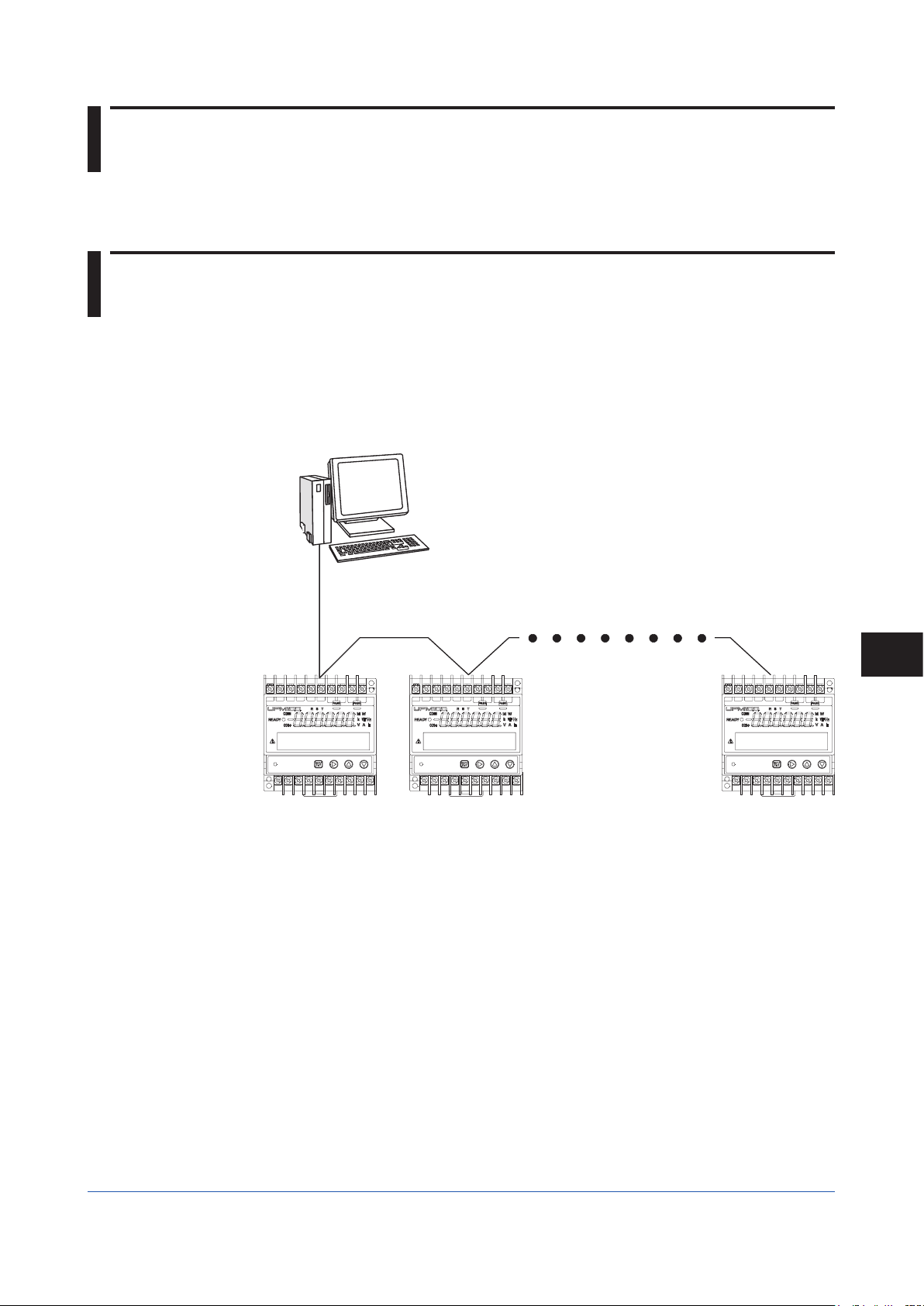
PC
080101E.EPS
Chapter 8 UPM01 Communication (Original Communication Protocol)
8
UPM01 Communication (Original Communication Protocol)
8.1 Overview
The UPM01 communication protocol uses specified categories to facilitate communications
not only with the UPM01, but also with the UPM02 and the UPM03. The specified categories
that can be used by the UPM100 are A, B, C, and E (the UPM100 is not designed to handle
D).
Hereinafter, PCs are generically called “higher-level devices.”
Maximum overall cable length of 1200 m for a maximum of 31 slave stations
8
UPM01 Communication
Figure 8-1 Example of Connection for UPM01 Communication
In this setting, the UPM100 as a slave returns a response to a command of a higher-level
device (master or slave). The UPM100 does not send a command.
IM 77C01H01-10EN
8-1
Page 88

8.2 Frame Configuration
The tables below show the frame configuration of commands sent from the higher-level
device to the UPM100 and that of responses sent from the UPM100 to the higher-level
device. Different elements are used for each category. For details, refer to “8.3 Functions.”
< Frame configuration of data sent from higher-level device to UPM100 >
Number
of bytes
Element
1 1 3 3
FRAME
LENGTH
(FLEN)
(1) (2) (3) (4) (5) (6) (7) (8)
Control
slot P
AP
command
Address
(SA)
Variable length
(0 to 53)
Data BCC ETX CR
2 1 1
< Frame configuration of data from UPM100 to higher-level device >
Number
of bytes
Element
1 1 3 3 Variable length 2 1 1
FRAME
LENGTH
(FLEN)
Control
slot U
AP
command
(3)
Address
(SA)
Data BCC ETX CR
(1) FRAME LENGTH (FLEN)
FLEN is the total number of bytes of “Control slot” + “AP Command” + “Station
Address” + “Data.” The number is a binary value, but not an ASCII code.
(2) Control Slot (P/U)
This slot determines whether the frame is a command (denoted by P) or a response
(denoted by U).
(3) AP Command
The contents differ depending on the value of the AP command (P or U).
8-2
P: Command
Number of bytes 1 1 1
Element READ/WRITE Category (X1) Data No. (X2)
U: Response
Number of bytes 1 1 1
Element READ/WRITE Category (X1) Status (S)
READ/WRITE
This slot indicates whether data are read (R), written (W), or re-read (F) (the UPM100
performs the same operation as R).
Category (X1)
Data are largely divided into five categories, denoted by A (measured value), B (statistical
data), C (set item), and E (user control item) (the UPM100 is not designed to handle D).
IM 77C01H01-10EN
Page 89

Data No (X2)
This slot indicates a subcategory of data, which can be specified by 0 to 9 and A to Z
(different depending on the category). Data to be written and data to be read are specified.
For details, refer to “8.3 Functions.”
Status (S)
This slot is used to return the status of the UPM100 (binary value). The “S” in the response
of the AP command is converted into a binary value, so each bit has a different meaning.
Element
b7: Unauthorized command
b6: UPM100 is not designed to handle
b5: Set value error
b4: Over-ranged Q (reactive power)
b3: Over-ranged I (rms current)
b2: Over-ranged V (rms voltage)
b1: Over-ranged P (rms power)
b0: UPM100 is not designed to hand
8.2 Frame Configuration
Bit b7 b6 b5 b4 b3 b2 b1 b0
CMD_ERR
TROUBLE VAL_ERR
OVR I_OVR V_OVR P_OVR NO_P
Note
The over-range threshold of the UPM100 (1.2 times that of the rated value) is used as the standard
specification value. The over-ranged values of reactive power and rms power are determined from
the sums of their respective measurements at all phases. Those of rms current and rms voltage are
determined from I1 and V1 measurements, respectively.
(4) Station Address (SA)
The values that can be assigned to SA are 001 to 031 (an ASCII code is sent).
(5) Data
An ASCII code or 16-bit value (binary) is used for representation. For details, refer to
“8.3 Functions.”
When the AP command indicates READ, data are set to the frame to send a response
to the higher-level device. When the AP command indicates WRITE, upon completion
of writing, the written data are read and set back to the frame, and a response is sent
to the higher-level device.
(6) BCC
The BCC slot performs the checksum function. The number of bytes of each slot
between the FRAME LENGTH slot and the Data slot is converted into a 1-byte
hexadecimal value. Then the value of each slot is summed. Each of the lower two
digits of the summed value is converted into an ASCII code to obtain 2-byte data.
8
UPM01 Communication
IM 77C01H01-10EN
8-3
Page 90

8.2 Frame Configuration
Note
A string of “&H” is added to a numerical value, so that it can be recognized as a hexadecimal value.
A to F of hexadecimal values must be uppercase.
Example) For a sum in hexadecimal value, &H234: 3 → &H33 and 4 → &H34 → “BCC
Example) For a sum in hexadecimal value, &H1DF: D → &H44 and F → &H46 → “BCC
= &H33 &H34.”
= &H44 &H46.”
(7) End of Text (ETX)
This slot indicates that the next slot is the last one of the frame. Its hexadecimal value
in ASCII code is &H03.
(8) Carriage Return (CR)
This slot is the last slot of the frame. Its hexadecimal value in ASCII code is &H0D.
8-4
IM 77C01H01-10EN
Page 91

8.3 Functions
This section describes the functions of commands and responses and the contents of
frames. For the meaning of each element, refer to “8.2 Frame Configuration.”
Slots between FRAME LENGTH (FLEN) and ETX as well as the CR slot are data
exchanged between the higher-level device and stations. The response status (S), the
station address (SA), and BCC do not have specific values, so the columns of these three
variables are blank in tables of this section. A data format is specified for each type of data.
8.3.1 Measured Items (Category A)
Data No.
*1
0 Batch transfer (Wh, P, V, I, Q, ɳ
1 Electric energy Wh
2 Power P
3 Voltage Vrms
4 Current Irms
5 Reactive power Q
6 UPM100 is not designed to handle
7 UPM100 is not designed to handle
8 All-harmonic distortion factor
9 Power P, reactive power Q
Description
*2
*2
)
*1: Data No. items in Category A.
*2: The UPM100 does not measure all-harmonic distortion factor. The measured value read out
is always “&H20,” for which no value is given (refer to Appendix, “ASCII Code Table”). The
sequence of the batch transfer is Wh, P, V, I, Q, ɳ. Each of these data has a specific data
format.
8
UPM01 Communication
IM 77C01H01-10EN
8-5
Page 92

8.3 Function
41555241103030313030303030303031 2B362E3531303045 2B312B322E333830
30452B312B382E30 303030452D332D30 2E30303030452D30 20202020202020202020
3542030D
080304E.EPS
< Command: Reading out >
Element FLEN P/U R/W X1
&H07 P R A 0 ETX CR
&H07 P R A 1 ETX CR
&H07 P R A 2 ETX CR
&H07 P R A 3 ETX CR
Data
&H07 P R A 4 ETX CR
&H07 P R A 5 ETX CR
&H07 P R A 6 ETX CR
&H07 P R A 7 ETX CR
&H07 P R A 8 ETX CR
&H07 P R A 9 ETX CR
< Response: Reading out >
X2
(Data No.)
SA BCC ETX CR
Example
Element FLEN P/U R/W X1 S SA Data format BCC ETX CR
&H07 U R A Batch transfer 58 ETX CR
&H07 U R A □□□□□□□□ Wh 8 ETX CR
&H07 U R A ± □.□□□□E±□ W 10 ETX CR
Data
&H07 U R A ± □.□□□□E±□ V 10 ETX CR
&H07 U R A ± □.□□□□E±□ A 10 ETX CR
&H07 U R A ± □.□□□□E±□ var 10 ETX CR
&H07 U R A □□□□□□□□□□ % 10 ETX CR
&H07 U R A Batch transfer 20 ETX CR
Unit
Data
length
To use Category A to send a batch transfer command (active energy, instantaneous
power,voltage, current):
Station address: 01
[Command]
07505241303030314142030D
[Response]
Wh
VA var Distortion factorA
W V
• A thin underline “_“ indicates a command. A thick underline “_“ indicates data to be read
out.
• Response data do not actually have spaces in between. Spaces are inserted in the
example above to make numbers easy to read.
• For analysis of response data, refer to Appendix, “ASCII Code Table.”
• The UPM100 does not measure all-harmonic distortion factor. The measurement is
always “20” (ASCII Code 20 means “blank”).
8-6
IM 77C01H01-10EN
Page 93

8.3.2 Statistical Items (Category B)
345552421030303130303030302D302E30303030452D30
30303030302D302E30303030452D30 30303030302D302E30303030452D303535030D
3535030D
080308E.EPS
Data No. Description
0 Time T + Average power P + Time T + Average voltage V + Time T + Average current I
1 Time Tp + Minimum power P + Time Tv + Minimum voltage V + Time Ti + Minimum current I
2 Time Tp + Maximum power P + Time Tv + Maximum voltage V + Time Ti + Maximum current I
* The unit of time is second. The maximum time is 5400 seconds, where the time is reset to 0.
< Command: Reading out >
Element FLEN P/U R/W X1
&H07 P R B 0 ETX CR
Data
< Response: Reading out >
&H07 P R B 1 ETX CR
&H07 P R B 2 ETX CR
X2
(Data No.)
8.3 Function
SA BCC ETX CR
Example
Element FLEN P/U R/W X1 S SA Data format BCC ETX CR
&H34 U R B □□□□□±□.□□□□E±□ₓ3
Data
&H07 U R B □□□□□±□.□□□□E±□ₓ3 8 ETX CR
&H07 U R B □□□□□±□.□□□□E±□ₓ3 10 ETX CR
□□□□□±□.□□□□E±□ₓ3 or the like: ASCII
Time T is a lapse of time between the last data communication and the one before. Tp, Tv, and Ti
are lapses of time between the time when the maximum or minimum value of power, voltage, and
current was measured, respectively, and the time when data communication to collect its statistics
occurred.
Data
Unit
length
s,W
58 ETX CR
s,V
s,A
s,W
s,V
s,A
s,W
s,V
s,A
To use Category B to send a command to read out “Time T + Average power P + Average
voltage V + Average current I”:
Station address: 01
[Command]
07505242303030314143
[Response]
8
UPM01 Communication
Time + Average power
Time + Average voltage Average voltage
• A thin underline “_“ indicates a command. A thick underline “_“ indicates data to be read
out.
• Response data do not actually have spaces in between. Spaces are inserted in the
example above to make numbers easy to read.
• For analysis of response data, refer to Appendix, “ASCII Code Table.”
IM 77C01H01-10EN
8-7
Page 94

8.3 Function
8.3.3 Set Items (Category C)
Data
No.
Description
0 PT (VT) ratio 1 to 6000 1 1
1 CT ratio 1 to 32000 1 1
2 Pulse width 10 to 1270 10 50 msec
3 Pulse weight 1 to 50000 1 1000 Wh/pls
Possible set
value range
Unit increment
Set unit
increment upon
shipping
Unit
Note
• After writing a set value, execute reset (manual or remote). It takes about 5 seconds for
restoration after resetting.
• The UPM100 can set the value of CT ratio down to the second decimal digit. However, when the
value is read out by the UPM01 communication protocol, decimal digits are truncated.
• The UPM100 is set to measure pulse width in increments of 10 msec. The UPM01
communication protocol truncates 1-msec-digit values.
• When a value out of the set value range is entered, a set value error is set to the status of the
response, and the currently set value is set to the response and returned.
< Command: Reading out >
Element FLEN P/U R/W X1 X2 (Data No.) SA BCC ETX CR
&H07 P R C 0 ETX CR
Data
&H07 P R C 1 ETX CR
&H07 P R C 2 ETX CR
&H07 P R C 3 ETX CR
< Command: Writing >
Element FLEN P/U R/W X1 X2 SA Data format BCC ETX CR
&H34 P W C 0 000001PT 8 ETX CR
Data
&H07 P W C 1 000001CT 8 ETX CR
&H07 P W C 2 000050MS 8 ETX CR
&H07 P W C 3 001000WH 8 ETX CR
Data length
< Response: Reading out/Writing >
Element FLEN P/U R/W X1 S SA Data format BCC ETX CR
&H34 U R/W C 000001PT 8 ETX CR
Data
&H07 U R/W C 000001CT 8 ETX CR
&H07 U R/W C 000050MS 8 ETX CR
&H07 U R/W C 001000WH 8 ETX CR
Data length
8-8
IM 77C01H01-10EN
Page 95

Example
0F55524310303031 3030303030315054 3546030D
080313E.EPS
0F55574310303031 3030303030325054 3635030D
080314E.EPS
8.3 Function
To use Category C to send a command to read out “PT ratio (VT ratio)”:
Station Address: 01
[Command]
07505243303030314144030D
[Response]
PT (VT) ratio
To use Category C to send a command to write 2 to “PT ratio”:
Station Address: 01
[Command]
0F5057433030303130303030303250543830030D
[Response]
PT (VT) ratio
• A thin underline “_“ indicates a command. A thick underline “_“ indicates data to be read
out.
• Response data do not actually have spaces in between. Spaces are inserted in the
example above to make numbers easy to read.
• For analysis of response data, refer to Appendix, “ASCII Code Table.”
• After writing, execute manual or remote reset. For remote reset commands, refer to the
examples in “8.3.4 User Control Items (Category E).”
8
UPM01 Communication
IM 77C01H01-10EN
8-9
Page 96

8.3 Function
8.3.4 User Control Items (Category E)
Data No. Description
0 Integration start Negative logic
1 Statistics reset Negative logic
2 Remote reset Positive logic
3 Wh initialization Negative logic
4 Error Status 1 –
5 Error Status 2 –
6 Error Count 2 –
* The Wh initialization command is executed upon reception, after which remote reset is not
needed (same as the standard operation of the UPM100).
< Command: Reading out >
Element FLEN P/U R/W X1 X2 (Data No.) SA BCC ETX CR
&H07 P R E 0 ETX CR
&H07 P R E 1 ETX CR
&H07 P R E 2 ETX CR
Data
&H07 P R E 3 ETX CR
&H07 P R E 4 ETX CR
&H07 P R E 5 ETX CR
&H07 P R E 6 ETX CR
< Command: Writing >
Element FLEN P/U R/W X1 X1 SA Data format BCC ETX CR
&H34 P W E 0 &H00/ Other than &H00 Integration start/stop 1 ETX CR
&H07 P W E 1 &H00/ Other than &H00
&H07 P W E 2 &H00/ Other than &H00
Data
&H07 P W E 3 &H00/ Other than &H00
&H07 P W E 4 &H40 Refer to Error Status 1 1 ETX CR
&H07 P W E 5 &H18 Refer to Error Status 2 1 ETX CR
&H07 P W E 6 &H20 Refer to Error Count 2 1 ETX CR
Description
Statistics reset/current
status retain
Current status retain/
remote reset
Wh initialization/
current status retain
Data
length
1 ETX CR
1 ETX CR
1 ETX CR
< Command: Reading out/Writing >
Element FLEN P/U R/W X1 S SA Data format BCC ETX CR
&H34 U R/W E &H00/ Other than &H00 "Integration start/stop 1 ETX CR
&H07 U R/W E &H00/ Other than &H00
&H07 U R/W E &H00/ Other than &H00
Data
&H07 U R/W E &H00/ Other than &H00
&H07 U R/W E &H40 Refer to Error Status 1 1 ETX CR
&H07 U R/W E &H18 Refer to Error Status 2 1 ETX CR
&H07 U R/W E &H20 Refer to Error Count 2” 1 ETX CR
Description
Statistics reset/current
status retain
Current status retain/
remote reset
Wh initialization/
current status retain
Data
length
1 ETX CR
1 ETX CR
1 ETX CR
8-10
IM 77C01H01-10EN
Page 97

Example
0855524530303031 00 4235030D
t
080319E.EPS
[Response]
0F55574310303031 3030303030325054 3635030D
080320E.EPS
8.3 Function
To use Category E to send a command to read out “Integration start”:
Station Address: 01
[Command]
07505245303030314146030D
[Response]
Integration star
To use Category E to send a command to write “Remote reset”:
Station Address: 01
[Command]
0F5057433030303130303030303250543830030D
[Response]
PT (VT) ratio
• A thin underline “_“ indicates a command. A thick underline “_“ indicates data to be read
out.
• Response data do not actually have spaces in between. Spaces are inserted in the
example above to make numbers easy to read.
• For analysis of response data, refer to Appendix, “ASCII Code Table.”
1. Error Status 1
No response is returned when an error is detected in the data link. The detected error is
indicated on Error Status 1. If there is a station that does not return a response within the
expected time, read out the error status immediately to receive the error contents in order to
find out the details of the error.
The contents of the error are saved in Error Status 1, which is updated as an error is
detected in the data link. By setting to 1 the remote reset status or the reset switch of the
UPM100’s main body, Error Status 1 is initialized (in other words, set to &H00, which means
there are no errors).
bit Error Description
7 Station address error An error in station address (the UPM100 is not designed to handle)
6 Blank
5 Blank
4 Blank
3 Control slot error The data in the control slot is not P/U.
2 Frame length error The FRAME LENGTH is different from the actual length of a frame.
1 Checksum error Inconsistency in checksum
0 UART error
An overrun error, noise flag, or framing error is detected by the MCU
(the UPM100 is not designed to handle).
8
UPM01 Communication
IM 77C01H01-10EN
8-11
Page 98

8.3 Function
2. Error Status 2, Error Count 2
A response is returned when an error is detected in the application. Error Status 2 and Error
Count 2 are updated as well. Error Count 2 counts from 0 to 255 and then goes back to 0.
By setting to 1 the remote reset status or the reset switch of the UPM100’s main body, Error
Status 2 and Error Count 2 are initialized (in other words, they are set to &H00, which means
there are no errors).
• When an unauthorized value is assigned
When VT ratio, CT ratio, pulse width, or pulse weight is set to an out-of-range value, bit5 of
the status of the response is set to 1. The current value of the data remains the same. By
reading out the status of the error immediately after its occurrence, it is possible to confirm
that bit4 of Error Status 2 in the User Controlled Items is set to 1.
• When an unauthorized command is executed
bit7 of the status of the response is set to 1. Also, one of bit0 to bit3 of Error Status 2 is set
to 1.
bit Error Description
7 Blank
6 Blank
5 Blank
4 Set value error Entry of an unauthorized value was attempted.
3 Memory access error
2 Fetch error Fetch was attempted under a condition that is not possible.
1 Write error Writing to read-only data was attempted.
0 INVALID command error There are invalid data in R/W, Category, or Data No.
An unauthorized access to the memory occurred
(the UPM100 is not designed to handle).
8-12
IM 77C01H01-10EN
Page 99

APP01E.EPS
DEL($7F): control code
Appendix
Appendix 1 Table of ASCII Codes (Alphanumeric Codes)
In order to implement PC link communication, create a transmission/receiving program by
referring to the Table of ASCII Codes below.
0
0
0
0
0
0
0
0
0
0
1
0
1
0
1
2
3
4
5
6
7
8
9
A
B
C
D
E
F
0
NUL DLE
SOH DC1
STX DC2
ETX DC3
EOT DC4
ENQ NAK
ACK SYN
BEL ETB
CAN
BS
EM
HT
SUB
LF
ESC
VT
FS
FF
GS
CR
RS
SO
US
SI
b1
b2
b3
b4
b5b6b7b8
0
0
0
0
1
0
0
0
0
1
0
0
1
1
0
0
0
0
1
0
1
0
1
0
0
1
1
0
1
1
1
0
0
0
0
1
1
0
0
1
0
1
0
1
1
1
0
1
0
0
1
1
1
0
1
1
0
1
1
1
1
1
1
1
SP
%
&
0
0
1
1
1
0
3
2
0
1
!
2
“
3
#
4
$
5
6
7
‘
8
(
9
)
:
*
;
+
<
,
=
-
>
.
?
/
@
1
1
0
0
1
0
5
4
P
Q
A
R
B
S
C
T
D
U
E
V
F
W
G
X
H
Y
I
Z
J
[
K
\
L
]
M
•
N
_
O
0
0
1
1
1
1
1
0
7
6
p
`
q
a
r
b
s
c
t
d
u
e
v
f
w
g
x
h
y
i
z
j
{
k
l
}
m
~
n
DEL
o
App
Appendix
IM 77C01H01-10EN
Control code Character code
Note: SP($20): space
App-1
Page 100

Blank
 Loading...