How it Works
Log In / Sign Up
Buy Points
How it Works
FAQ
Contact Us
Questions and Suggestions
Users
Yokogawa
Loading...
S
SR10001
SR10002
SR10003
SR10004
SR10006
SS380G
STARDOM FCN
Stardom FCN-100
STARDOM FCN-500
STARDOM FCN-RTU
Sted
2
Sushi Sensor
SX42
T
TA120F
TA220
2
TA320
TA520
2
TA720
2
TB200
TB400G
TB750G
2
TC10
5
TC10-L
4
TDLS200
3
TDLS220
3
TDLS8000
TDLS8200
TIO0110
TM10
TM20
2
TX10
3
TX10-01
TX1002
2
TX1003
2
TY500
TY700
2
TY710
TY720
U
UD310
UD350
UM330
5
UM331
2
UM33A
3
UM33A/S006
UM350
2
UP150
2
UP32A
2
UP350
3
UP35A
4
UP550
7
UP55A
4
UP750
10
UPM100
2
UPM101
2
UR5AP3
US1000
2
US300FM
US300PM
UT130
2
UT150
5
UT150L
3
UT152
2
UT155
2
UT320
3
UT32A
13
UT32A-C
UT32A-D
UT32A-D/MDL
UT32A/MDL
UT32A-R
UT32A/RSP
UT32A-V
UT350
4
UT350L
3
UT35A
10
UT35A-L
3
UT35A/MDL
UT35A/RSP
UT450
2
UT520
2
UT52A
10
UT52A/MDL
UT550
8
UT55A
9
UT55A/MDL
UT750
12
UT75A
3
UV700G
UZ005
UZ011
V
VB8000
VC3300
VJ
VJ77
3
VJA1
2
VJA4
2
VJA5
VJA7
VJAK
VJCE
Loading...
Loading...
Nothing found
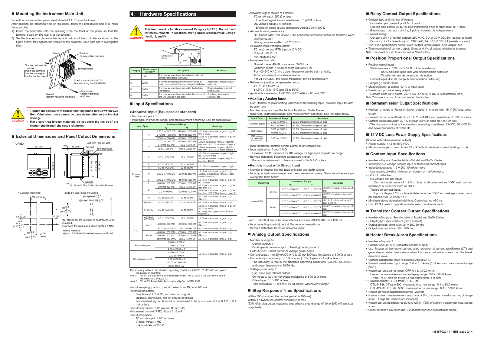
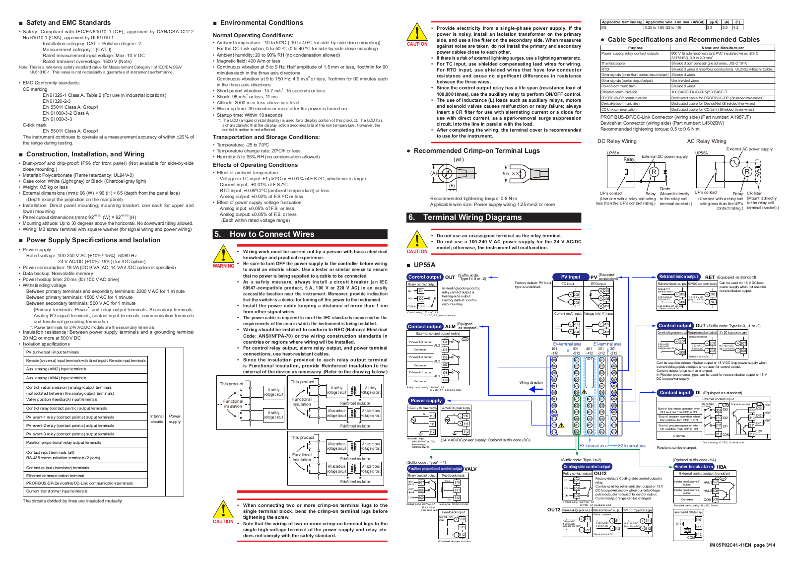
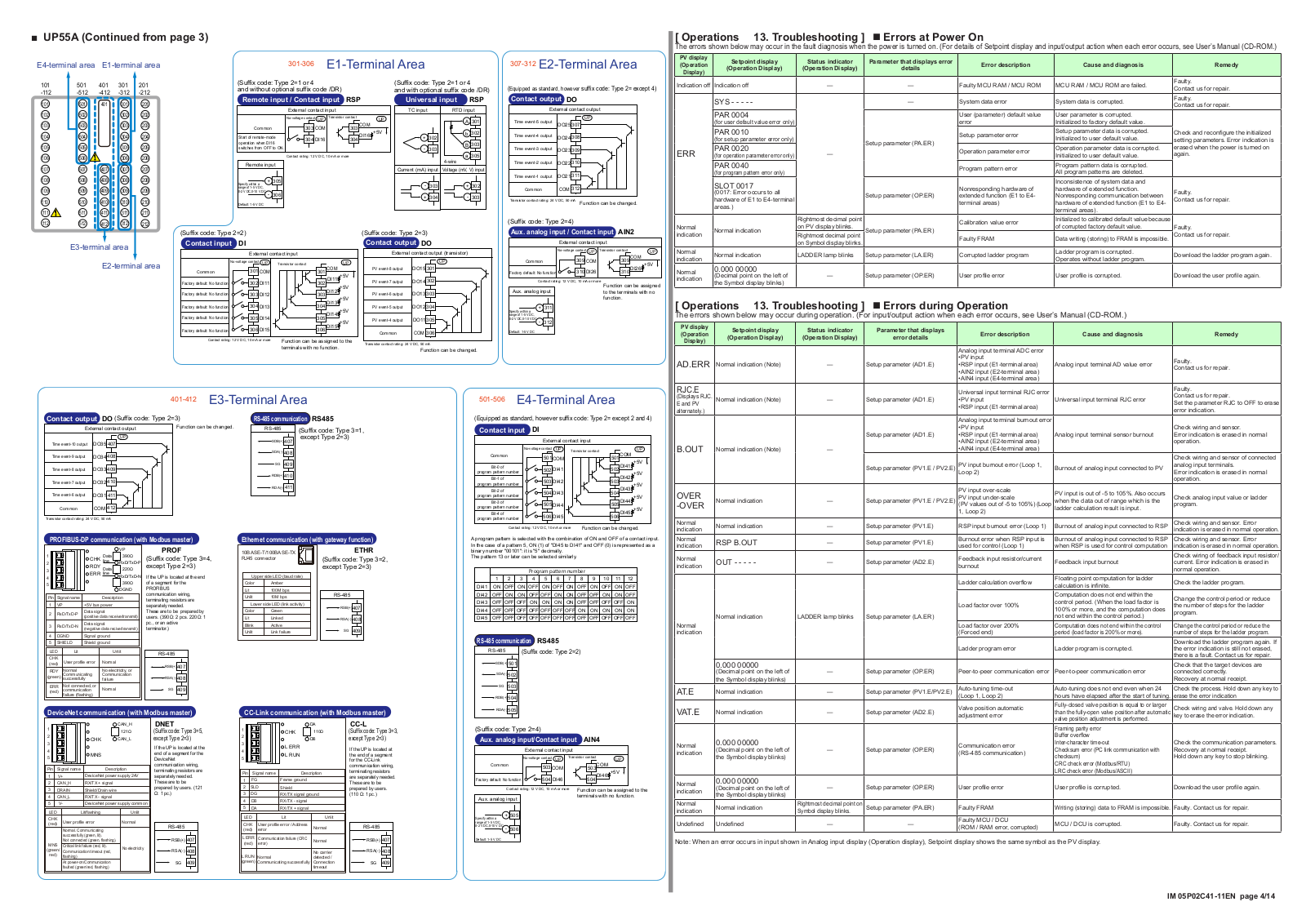
UP55A
Operating Manual
510 pgs
19.25 Mb
0
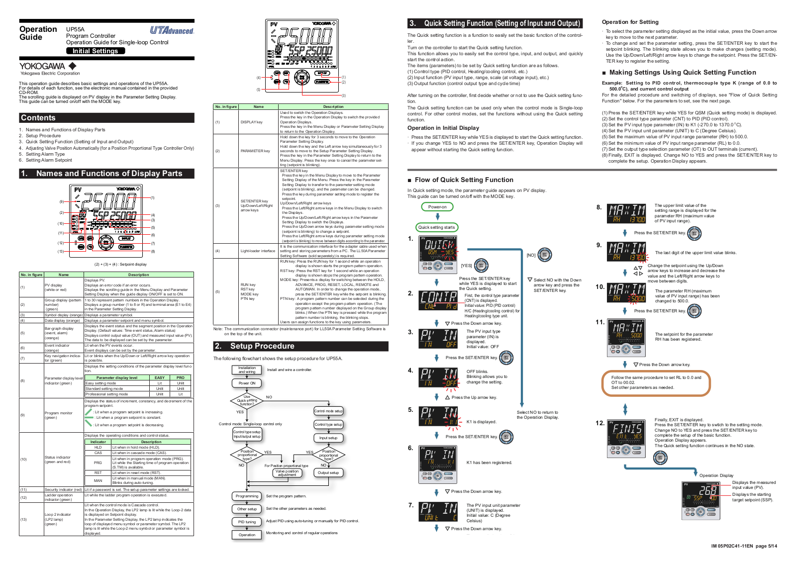
Operating Manual
14 pgs
10.62 Mb
0
Specifications
13 pgs
986.73 Kb
0
User Manual
516 pgs
17.18 Mb
0
Table of contents
Loading...
Yokogawa UP55A Operating Manual
...
Yokogawa Operating Manual
Download
Specifications and Main Features
Frequently Asked Questions
User Manual
Download
Page 1
Page 2
Page 3
Page 4
Page 5
Page 6
Page 7
Page 8
Page 9
Page 10
Page 11
Page 12
Page 13
Page 14
Loading...
+
hidden pages
Unhide
You need points to download manuals.
1 point = 1 manual.
You can buy points or you can get point for every manual you upload.
Buy points
Upload your manuals