

Page 1
<<Contents>> <<Index>>
General
Specifications
MODEL UP350
Program Controller
GS 05E01D02-01E
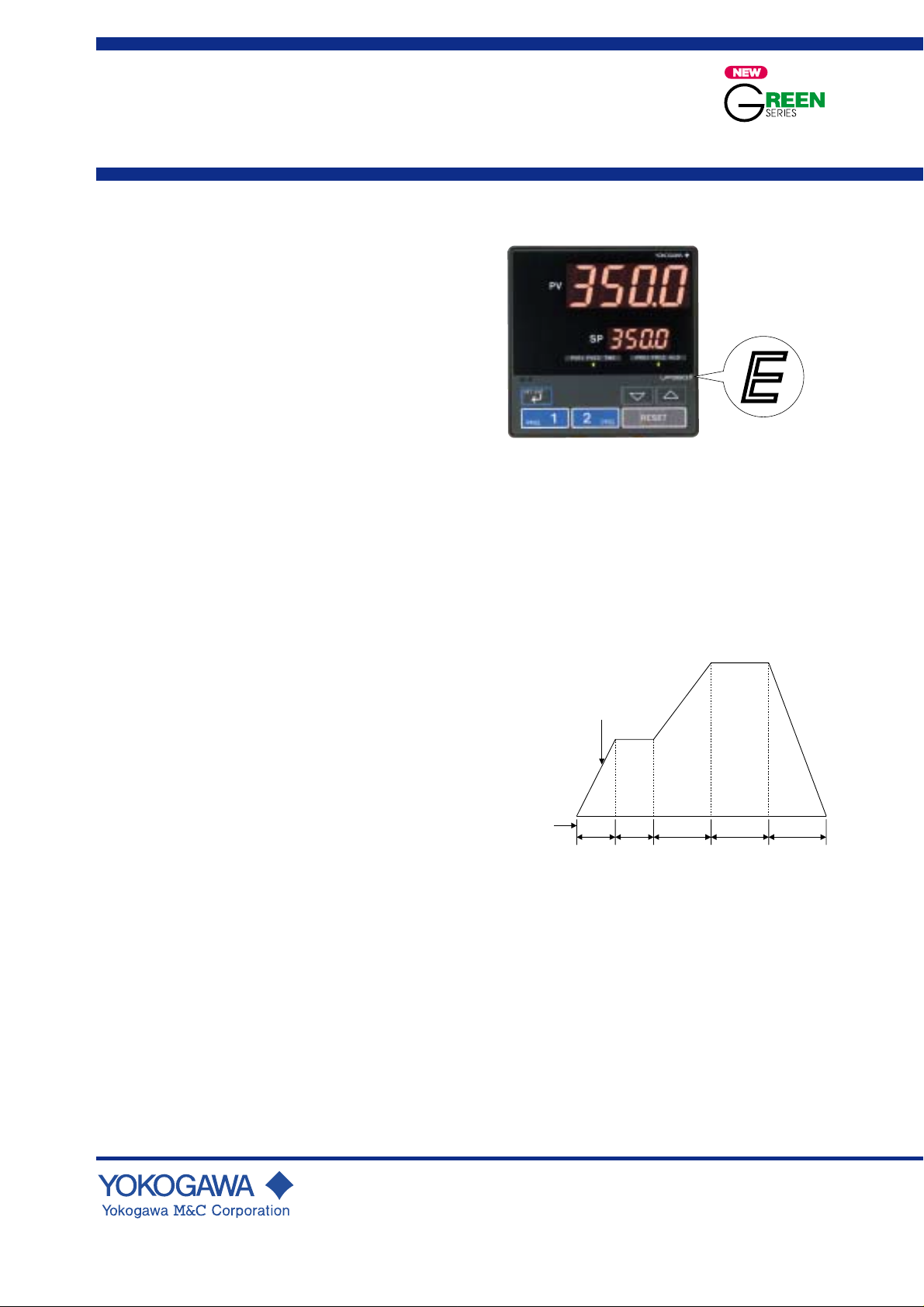
■General
Model UP350 program controller is a precision controller,
featuring two program profiles and universal input/output.-
For easy operation, it is provided with a large display for
process variables, two program operation keys, and a
program reset key. For excellent controll, auto-tuning, PID
control with the “SUPER” overshoot suppressing function
and the "SUPER2" hunting suppressing function are
available. It also has a retransmission output and 15V DC
loop power supply as standard.
■Main Features
• Extra-large digital display allows the indicated values to be
read even from a long distance. LEDs of 20mm height are
used for the process variable display.
• It can store two program pattern types. Programmed
operation can be started by using the two program
operation keys on the front panel and terminated by using
the reset key.
• Universal input and output enable users to set or change
freely the type of measured inputs (thermocouple, RTD, or
DCV), measurement range, type of control output (4 to 20
mA current, voltage pulse, or relay contact, etc. from the
front panel.
• Parameters can be easily set using a personal computer.
("Parameter setting tool (model LL100)" sold separately is
required.)
• Various communication function are provided.
Communication is possible with personal computer,
programable logic controller, and other controllers.
UP350
UP350E
“E” indicates with the
model with expanded
functions.
Starting/stopping (resetting) a program pattern:
A program pattern can be started or stopped
(reset) by key operation.
Temporarily stopping (holding) a program pattern:
A program pattern can be temporarily stopped
(hold) by key operation or through the contact
input.
Skipping (advancing) the segment of a program:
Available through key operation
Switching between program patterns:
Available through key operation or external
contact
Target setpoint
SP
■Function Specifications
● Program Setting Function
“Program setting” allows the controller's target setpoint to
increase or decrease along the program pattern versus time.
The instrument, provided with two program patterns, can be
operated by using the front panel key or through the external
contact. One program pattern consists of 10 broken lines
(program segments). If the two program patterns are
combined, a program pattern of up to 20 segments can be
created. The length of each segment can be specified by the
segment time. Users can also configure the number of
repeats, event outputs, etc.
Number of program patterns: 2
Number of segments/pattern: 10
Number of program repeat: Unlimited repeats
Segment time: 0 min. 0 s to 99 min. 59 s, or
0 h 0 min. to 99 h 59 min.
Segment time
t1 t2 t3 t4 t5
Segment
Segment
No.1
No.2
˙˙˙˙˙˙
GS 05E01D02-01E
© Copyright Jan. 2000 (YK)
1st Edition Mar. 2000 (YG)
Segment
No.5
Page 2
<<Contents>> <<Index>>
2
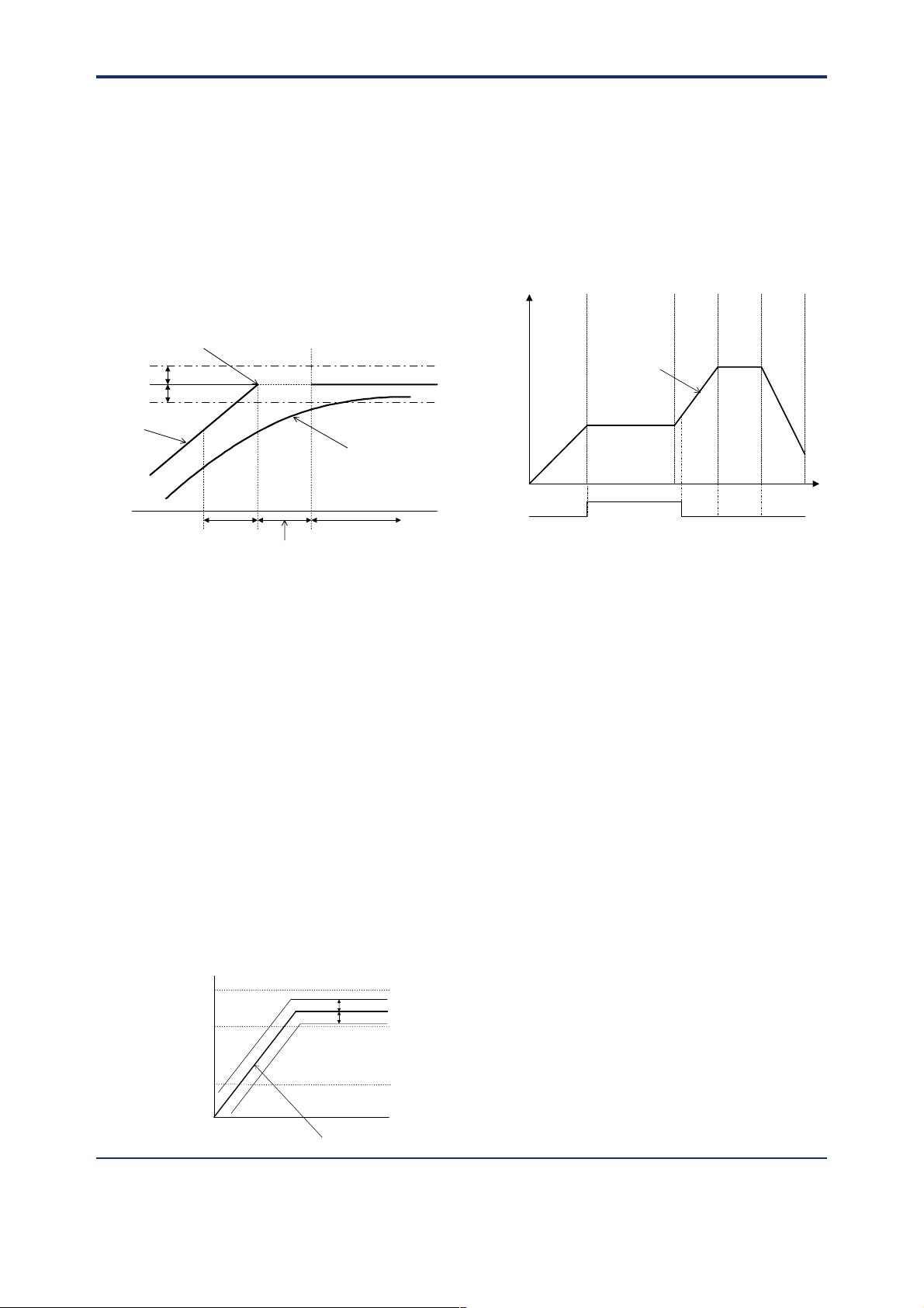
Wait Function (Guaranteed soak)
The function to delay the progress of a program pattern if the
process variable (PV) has not reached the target setpoint
(SP). The wait zone is the deviation band of acceptable PV
response is determined, and the wait time is the time to wait
for the PV to reach the wait zone. If the PV reaches the wait
zone within a certain time (the wait time), then the program
will advance to the next segment. If it does not reach the wait
zone after the wait time has elapsed, then the program will
eventually advance to the next segment.
Wait time: 0 min. 1 s to 99 min. 59 s, or
0 h 1 min. to 99 h 59 min.
Wait zone: OFF, 0.0 to 10.0 % of measured input range
width.
Wait zone
Wait zone
SP
TSP
Seg.n
EVn EVn+1
Wait time
Seg.n+1
PV
Program Setting Function and PID Parameter
Switching
PID parameter switching in accordance with the progress of
the program pattern is available.
Zone PID: PID parameter selection according to the
Reference point method:
Reference point = Measuring input range (0%)
Reference point hysteresis = Fixed to 0.5% of the
Reference deviation method:
Reference deviation = OFF, 0.1 to 100.0% of
Measuring input range (100%)
Measuring input range (0%)
value of the PV is available. Reference point
(setpoint for PID parameter switching) or
reference deviation is used for switching.
Up to two points can be set to divide the PV
range up to three zones, and this selects the
PID parameter set (PID 1 to 3) according to
zone.
Reference point 1 Reference point 2
Measuring input range (100%)
measured input range width.
Switches the group of PID parameters (PID
4) depending on whether the control
deviation is within or over the reference
preset amount. This takes priority over the
reference point.
measured input range width.
Reference deviation
Reference point 2
Reference point 1
Reference deviation
Measured value (PV)
No.3PID
No.2PID
No.1PID
Time Event: 1 point
A time event may be set thruoghout the program pattern
progress, by and uses a status lamp or a contact output.
Number of time events: 1 point for each program pattern
Time event setting points: These output time events
according to the elapsed time from the
program start.
Time event setting range(ON and OFF): 0 min. 1 s to 99
min. 59 s, or
0 h 1 min. to 99 h 59 min.
Time event display: 1 point (TIME)
Time event contact output: 1
SEG1 SEG2 SEG3 SEG4 SEG5
Program pattern
Time event
ON time OFF time
PV Event: 2 point
A PV event is a PV/deviation alarm which is configured in
accordance with the program pattern. The alarm status is
indicated by the event LED on the front of the instrument
panel.
Number of PV events:
2 points maximum per program pattern
PV event LEDs:
2 points (PVE1, PVE2)
PV event types:
PV high limit, PV low limit, Deviation high
limit, Deviation low limit, Deenergized on
deviation high limit, Deenergized on deviation
low limit, Deviation high and low limits, High
and low limits within deviation, Deenergized
on PV high limit, Deenergized on PV low
limit
PV event setting ranges:
PV alarm: -100.0 to 100% of measured input range.
Deviation alarm: -100.0 to 100% of measured input
range width.
Alarm hysteresis: 0.0 to 100.0% of measured input range
width.
● Control Computation Functions
Control computation:
Control cycle time: 250 ms
Number of PID parameter sets: 4
Auto-tuning: Available as standard. If auto-tuning is
Select from the following types of control
strategies:
Continuous PID control, time proportional
PID control, Relay ON/OFF control
enabled, the PID constant is set automatically.
(Limit cycle method)
Time
All Rights Reserved. Copyright © 2000, Y okogawa M&C Corporation
GS 05E01D02-01E 1st Edition Mar.31, 2000-00
Page 3

<<Contents>> <<Index>>
3
“SUPER” function: This suppresses overshooting caused
by the sudden change of the target setpoint or
disturbance.
“SUPER2” function:
This stabilizes the state of control that is
unstable due to hunting, etc. without requiring
any change in PID constants, when the load
and/or gain varies greatly, or when there is a
difference between the characteristics of
temperature zones.
Control Parameters Setting Range
Proportional band: 0.1 to 999.9%
Integral time: 1 to 6,000 s, or OFF (for Manual Reset)
Derivative time: 1 to 6,000 s, or OFF
Manual reset value: -5.0 to 105.0% of output range
(functions when integral time is off)
ON/OFF control hysteresis: 0.0 to 100.0% of measured
input range width
Direct/Reverse action:
Defining the direction of an increase/decrease
in output corresponding to a positive or
negative deviation is available.
Anti-reset windup:
When the output of the controller is limited,
this stops normal integration to suppress overintegration; instead, it performs anti-reset
windup computation.
Control output cycle time: 1 to 1000 s
Preset output value: -5.0 to 105.0% of output range
Output tracking:
Selecting output with bump or without bump
is available by changing the PID control
mode.
Output limiter:
high limit: Low limit to 105.0% of output range
low limit: -5.0% of output range to high limit
● Signal Computation Functions
Measured input configuration:
Bias addition (-100.0 to 100.0% of measured
input range width.), first order lag filter (time
constant: off, 1 to 120 s)
Contact input function:
Program pattern switching operation, program
operation hold mode switching, display key-
lock parameter enabled/disabled switching
For program pattern operation, select from the
dual-pattern switching operation and single-
pattern operation.
• If the single-pattern operation is selected,
program operation hold mode switching can
also be used.
• If the dual-pattern switching operation is
selected, program operation hold mode
switching cannot be used.
If displaying key-lock parameter enabled/
disabled switching is used, switching between
the single-pattern operation and dual-pattern
switching operation is not available.
Status indicating lamps:
2 PV event (alarm) LEDs: PVE1, PVE2
1 time event LED: TME
2 program operation number LEDs: PRG1, PRG2
1 program operation hold LED: HLD (lights up during
hold mode)
Operation key:
▲, ▼ key: Increases/decreases the value of setpoint or
other parameters which appear on LED
display.
SET/ENT key: Sets/changes the setting value, and calls/
switches between parameters.
PRG1, PRG2: Program operation control key
RESET: Program operation stop key
SELECT display:
Allows selection and registration of
frequently changed parameters from the
operation parameters during operation. For
example, if the bias parameter is registered
in the SELECT display, the setpoint can
easily be displayed during operation.
Security function:
An operation inhibiting mode using a
password is available.
● Communication Functions (optional)
The communication function, provided with the instrument,
allows connection to personal computer, programmable logic
controller, and other GREEN series controllers.
Communication protocol:
Computer link communication:
Communication protocol with a personal
computer
Ladder communication:
Communication protocol with programmable
logic controller
MODBUS communication:
Communication protocol with a personal
computer or PLC.
Coordinated operation:
Protocol to realize coordinated operation
with more than one UT controller in the
GREEN series. The UP350 is always
configured as a master unit.
Communication interface:
Communication protocol:
Computer link, ladder communication,
MOBUS or coordinated operation
Standard: EIA RS485
Maximum number of connectable controllers:
31 Green series controllers
Maximam communication distance: 1,200 m
Communication method:
Two-wire half duplex or four-wire half
duplex, start-stop synchronization system,
handshaking
Communication rate:
600, 1200, 2400, 4800, 9600 bps
● Display and Operation Function
PV display: 4-digit digital display for engineering data
Setpoint display:
All Rights Reserved. Copyright © 2000, Y okogawa M&C Corporation GS 05E01D02-01E 1st Edition Mar.31, 2000-00
Various types of data, including setpoint (SP),
are available selectively on 4-digit digital
display.
Page 4

<<Contents>> <<Index>>
Status lamps
PV event (PVE1, PVE2), time event (TME),
operation status of Program pattern 1 or 2
(PRG1, PRG2) hold status (HLD).
Communication port for light loader
Parameters and programs are set via
communication from a personal computer.
Operational keys
Increase/Decrease the setting data (䉱, 䉲)
Select parameter/Enter the setting data (SET/ENT)
Start program operation or set a program(PRG1, PRG2)
Reset to preset output(RESET)
Sample structures of communication systems
(1) Computer link communication/MODBUS communication (2) Ladder communication
4
LED display unit (for PV)
Display PV, and error code when
error is detected.
LED display unit (for SP)
Display setpoint (SP),
setting item/value of parameters.
Personal computer
PV
PV
PV2
AL
1
2
3
REM
4
MAN1
MAN2
STP
CAS
A/M
DISP
SET/ENT
PV
PV2
PV2
AL
AL
1
1
2
2
3
3
REM
REM
4
4
MAN1
MAN1
MAN2
MAN2
STP
STP
CAS
CAS
A/M
A/M
DISP
DISP
SET/ENT
SET/ENT
PV
PV2
AL
1
2
3
REM
4
MAN1
MAN2
STP
CAS
A/M
DISP
SET/ENT
UP350
Program coutroller
(3) Coordinated operation
PV
PV2
AL
1
UP350 Program controller
2
3
REM
4
MAN1
MAN2
STP
CAS
A/M
DISP
SET/ENT
or UT350/UT320 Digital indicating controller
PV
PV
PV2
AL
1
2
3
REM
4
MAN1
MAN2
STP
CAS
A/M
DISP
SET/ENT
PV
PV2
PV2
AL
AL
1
1
2
2
3
3
REM
REM
4
4
MAN1
MAN1
MAN2
MAN2
STP
STP
CAS
CAS
A/M
A/M
DISP
DISP
SET/ENT
SET/ENT
PV
PV2
AL
1
2
3
REM
4
MAN1
MAN2
STP
CAS
A/M
DISP
SET/ENT
UT350/UT320
Digital indicating controller
■Hardware Specifications
Measured Input Signal
Number of inputs: 1 point
Input type: Possible to select input type/measurement
Input type, measurement ranges, and measurement accuracy:
Burnout detection:
Input bias current: 0.05 µA (for TC and RTD b-terminal)
Measuring current(RTD): about 0.13mA
Input resistance:
Allowable signal source resistance:
Allowable leadwire resistance:
ranges from the input list with software.
Refer to the table in the next page.
Available with TC, RTD, stadard signal, 0.4 to
2 V DC and 1 to 5 V DC.
Up-scale, down-scale, and off can be set.
For standard signal, an input of 0.1V or less is
regarded as burnout.
1 MΩ or more for TC/mV input
About 1 MΩ for DC voltage input
250 Ω or less; effect of permissible signal
source resistance 0.1 µV/Ω or less for TC/mV input
2 kΩ or less; effect of permissible signal
source resistance 0.01%/100 Ω or less for DC
voltage input
Max. of 150 Ω/wire (resistance in each of
three wires must be equal) for RTD input
However, 10 Ω/wire in the range of -150.0 to
150.0°C.
MELSEC-A
PLC
PV
PV
PV2
PV2
AL
AL
1
1
2
2
3
3
REM
REM
4
4
MAN1
MAN1
MAN2
MAN2
STP
STP
CAS
CAS
A/M
A/M
DISP
SET/ENT
PV
PV2
AL
1
2
3
REM
4
MAN1
MAN2
STP
CAS
A/M
DISP
SET/ENT
DISP
SET/ENT
PV
PV2
AL
1
2
3
REM
4
MAN1
MAN2
STP
CAS
A/M
DISP
SET/ENT
UP350
Plogram controller
Effect of permissible leadwire resistance
±0.1°C/10 Ω or less
Allowable input voltage:
±10 V DC for TC/mV/RTD input
±20 V DC for DC voltage input
Noise rejection ratio:
Normal mode 40 dB (50/60 Hz) or more
Common mode 120 dB (50/60 Hz) or more
Reference-junction compensation error:
±1.0°C (15 to 35°C), ±1.5°C (0 to 15°C, 35 to
50°C)
Applicable standards: JIS, IEC, or DIN (ITS-90) for TC
and RTD
15V DC Loop Power Supply
The controller supplies power to a two-wire transmitter.
Place a resistor (10 to 250 Ω, optional) between the controller and the transmitter, convert a current signal to a voltage
signal, and read it from the PV input. Either the retransmission output or the loop power supply can be used.
Supply voltage is 14.5 to 18.0 V DC. Maximum supply
current is about 21 mA (with a protection circuit for a field
short-circuit).
All Rights Reserved. Copyright © 2000, Y okogawa M&C Corporation
GS 05E01D02-01E
1st Edition Mar.31, 2000-00
Page 5

<<Contents>> <<Index>>
5
■
15 V DC Power Supply Wiring to Two-wire Sensor
Control Outputs
The control output is of a universal scheme and can be
selected from the following types of outputs.
Two-wire transmitter
4-20mADC
External
resistor
(Note)
12
100Ω
13
14
15
PV input
0.4 to 2.0 V DC signal
Loop power
supply
14.5 to
18.0 V DC
Current output
Number of output points: 1
Output signal: 4 to 20 mA
Load resistance: 600 Ω or less
Output accuracy: ±0.3% of span
Performance in the standard operating
conditions (at 23± 2°C, 55± 10% RH, and
50/60 Hz power frequency)
Voltage pulse output
Number of outputs: 1
Note: Connecting a 100 Ω resistor to the terminals is optional.
Model: X010-100-2 (resistor with M3.5 crimp-on terminal lugs)
Output signal: ON voltage 12 V DC (for load resistance
of 600Ω or more, short-circuit current
approximately 30 mA)
Retransmission Output
Either PV, target setpoint, or control output is output. Either
the retransmission output or the 15 V DC loop power supply
can be used.
Number of output points: 1 point
Output signal: 4 to 20 mA DC
Load resistance: 600 Ω or less
Output accuracy: ±0.3% of span
Resolution: 10 ms
Relay contact output
Number of outputs: 1
Output signal: Transfer contact, including NC, NO, and
Standard rating: 250V AC 3A or 30V DC 3A
Resolution: 10ms
OFF voltage 0.1V DC or less
Common.
(Load resistance)
Performance in the standard operating
conditions (at 23± 2°C, 55± 10% RH, and 50/
60 Hz power frequency)
Input type
Unspecified(when shipped from the factory)
Thermocouple
RTD
Standard
signal
DC voltage
K
J
T
B
S
R
N
E
L (DIN)
U (DIN)
W (DIN)
Platinel 2
PR20-40
W97Re3-W75Re25
JPt100
Pt100
0.4 to 2V
1 to 5V
0 to 2V
0 to 10V
-10 to 20mV
0 to100mV
Input range
code
OFF
1
2
3
4
5
6
7
8
9
10
11
12
13
14
15
16
17
18
30
31
35
36
37
40
41
50
51
55
56
Note1:The accuracy is ±0.3°C of instrument range ±1 digit for a temperature range from 0 to 100°C.
Note2:The accuracy is ±0.5°C of instrument range ±1 digit for a temperature range from –100 to 200°C.
*1: Performance in the standard operating conditions (at 23±2°C, 55±10% RH, and 50/60Hz power frequency)
Instrument
range (°C)
Set the data item PV input type “IN” to the OFF option to leave the PV input type undefined.
-200 to 1370˚C
-199.9 to 999.9˚C
-199.9 to 500.0˚C
-199.9 to 999.9˚C
-199.9 to 400.0˚C
0.0 to 400.0˚C
0 to 1800˚C
0 to 1700˚C
0 to 1700˚C
-200 to 1300˚C
-199.9 to 999.9˚C
-199.9 to 900.0˚C
-199.9 to 400.0˚C
0.0 to 400.0˚C
0 to 2300˚C
0 to 1390˚C
0 to 1900˚C
0 to 2000˚C
-199.9 to 500.0˚C
-150.0 to 150.0˚C
-199.9 to 850.0˚C
-199.9 to 500.0˚C
-150.0 to150.0˚C
0.400 to 2.000 V
1.000 to 5.000 V
0.000 to 2.000 V
0.00 to 10.00 V
-10.00 to 20.00 mV
0.0 to 100.0 mV
Instrument
range (°F)
-300 to 2500˚F
0 to 2300˚F
-199.9 to 999.9˚F
-300 to 2300˚F
-300 to 750˚F
-199.9 to 750.0˚F
32 to 3300˚F
32 to 3100˚F
32 to 3100˚F
-300 to 2400˚F
-300 to 1800˚F
-300 to 1300˚F
-300 to 750˚F
-199.9 to 750.0˚F
32 to 4200˚F
32 to 2500˚F
32 to 3400˚F
32 to 3600˚F
-199.9 to 999.9˚F
-199.9 to 300.0˚F
-300 to 1560˚F
-199.9 to 999.9˚F
-199.9 to 300.0˚F
Scaling is enable in the
following 4 range.
-1999 to 9999
-199.9 to 999.9
-19.99 to 99.99
-1.999 to 9.999
At or above 0˚C ±0.1% ±1 digit of F.S.
Below 0˚C, ±0.2% ±1 digit of F.S.
At or above 400˚C ±0.15% ±1 digit of F.S.
Below 400˚C ±5% ±1 digit of F.S.
±0.15% ±1 digit of F.S.
±0.1% ±1 digit of F.S.
Below 0˚C ±0.25% ±1 digit of F.S.
At or above 0˚C ±0.1% ±1 digit of F.S.
Below 0˚C ±0.2% ±1 digit of F.S.
±0.2% ±1 digit of F.S.
±0.1% ±1 digit of F.S.
At or above 800˚C ±0.5% ±1 digit of F.S.
Below 800˚C, not guaranteed
±0.2% ±1 digit of F.S.
±0.1% ±1 digit of F.S. (Note1) (Note2)
±0.2% ±1 digit of F.S. (Note1)
±0.1% ±1 digit of F.S. (Note1) (Note2)
±0.2% ±1 digit of F.S. (Note1)
±0.1% ±1 digit of F.S.
Instrument accuracy
*1
All Rights Reserved. Copyright © 2000, Y okogawa M&C Corporation GS 05E01D02-01E
1st Edition Mar.31, 2000-00
Page 6

<<Contents>> <<Index>>
6
Contact Inputs
Usage: Program pattern selection, program operation
hold mode switching, display key lock
parameter enabled/disabled switching
Number of inputs: 2 points
Input type: non-voltage contact input or transistor open
collector input
Input contact capacity: 12 V DC, 10 mA or more (for non-
voltage contact input)
On/off detection:
For non-voltage contact input,
ON=contact resistance of 1kΩ or less,
OFF=contact resistance of 20kΩ or more.
For transistor open collector input,
ON=2V or less,
OFF=leak current of 100µA or less.
Minimum retention time for status detection: about 1 s
Contact Outputs
Usage: Event output
Number of relay contact outputs: 3 points
Relay contact rating: 240 V AC 1A, or 30 V DC 1A,
make contact
● Display Specifications
Process variable display unit:
4-digit 7-segment red LED; each digit 20 mm
in height
Parameter display:
4-digit 7-segment red LED; each digit 9.3 mm
in height
Status indicating lamps: LEDs
● Conformance to Safety and EMC Standards
Safety standard:
Conforms to IEC1010-1: 1990 and EN61010-
1: 1992.
Certified for CSA1010. The voltage category
of each input is CAT II (IEC1010-1)
Certified for UL 508 application
EMC standards:
Conforms to the following standards.
During test, the controller continues to operate
with the measurement accuracy within ±20%
of the range.
EMI (Emission) EN61326-1: 1997+Am1: 1998
EMS (immunity) EN61326-1: 1997+Am1: 1998
● Construction, Installation, and Wiring
Structure: Dust-proof and Drip-proof front panel
conforming to IP55.
For side-by-side close installation, the
controller loses its dust-proof and drip-proof
Body construction: ABS resin and polycarbonate
Case color: Black
Weight: Approx. 1 kg or less
Dimensions: 96W × 96H × 100D (from the front panel)
Mounting: Direct panel mounting; mounting bracket, one
Panel cutout dimensions:
Mounting attitude: Up to 30 degrees above the horizontal.
Wiring: M3.5 screw terminal (signals, power supply/
protection.
(mm)
each for upper and lower mounting.
92
+0.8
0
(W) ×
92
+0.8
(H) mm
0
No downward tilting allowed.
ground)
● Power Supply / Isolation
Power supply: Voltage rating at 100 to 240 V AC (±10%),
50/60 Hz
Power consumption: MAX. 20VA (MAX. 8.0W)
Memory back-up: Non-volatile memory (Service life
approx. 100,000 times of writings)
Withstanding voltage:
Between primary terminal and secondary terminal:
1500V AC for 1 min. (Note)
Between primary terminal and ground terminal:
1500V AC for 1 min. (Note)
Between ground terminal and secondary terminal:
1500V AC for 1 min.
Between two secondary terminals:
500V AC for 1 min
Primary terminal: Power supply, relay output
Secondary terminal:
Analog input/output signal terminals,
voltage pulse output terminal, contact
input terminal
Note. The withstanding voltage is specified as 2300V AC
perminute to provide amargin of safety .
Isolation resistance:
Between power supply terminal and ground
terminal, 500 V DC 20 MΩ
Ground: class 3 grounding (grounding resistance of
100Ω or less)
Isolation Specifications:
Measured input terminal:
Isolated from other input/output terminals.
Not isolated from internal circuit.
Control output (current or voltage pulse output) and
retransmission terminals: Not isolated
between control and retransmission output
terminal mutvally, output terminals, Isolated
from other input/output terminals and
internal circuit.
Relay contact control output terminals:
Isolated from other I/O terminals and
internal circuits.
Contact input terminal:
Not isolated from contact input terminals
mutually and communication terminals.
Isolated from other input/output terminals
and internal circuit.
Relay contact event output terminal:
Isolated from other input/output terminals
and internal circuit.
RS-485 communication terminal:
Not isolated from contact input terminals.
Isolated from other input/output, ground and
internal terminals.
Power supply terminal:
Isolated from other input/output and ground
terminals, and internal circuit.
Ground terminal:
Isolated from other input/output and ground
terminals, and internal circuit.
All Rights Reserved. Copyright © 2000, Y okogawa M&C Corporation
GS 05E01D02-01E
1st Edition Mar.31, 2000-00
Page 7

<<Contents>> <<Index>>
7
● Environmental Conditions
Normal operating conditions:
Ambient temperature: 0° to 50°C (less than 40°C when
Ambient temperature change limit:10°C/h or less
Ambient humidity: 20 to 90% RH (non-condensing)
Magnetic field: 400 A/m or less
Continuous vibration (5 to 14 Hz):
Continuous vibration (14 to 150 Hz):
Short-period vibration: 14.7 m/s2, 15s. or less
Shock: 147 m/s
Installation altitude:
Warm-up time: 30minutes or more
mounted side by side)
Amplitude of 1.2 mm or less
2
or less
4.9 m/s
2
or less, 11 ms.
2,000 m above sea level maximum
Transit/storage conditions:
Temperature: -25° to 70°C
Temperature change limit:20°C/h or less
Humidity: 5 to 95% RH (non-condensing)
Effects on operating conditions
Effect of ambient temperature:
For voltage/TC input, within ±1µV/°C and ±0.01% of
F.S./°C, whichever is greater.
For RTD input, within ±0.05 °C/°C (ambient tempera-
ture)
For analog output, ±0.05% of F.S./°C or less
Effect of power supply fluctuation (within rated voltage
range):
For analog input, within ±1µV/10V and ±0.01% of
F.S./10V, whichever is greater.
For analog output, within ±0.05% of F.S./10V
All Rights Reserved. Copyright © 2000, Y okogawa M&C Corporation GS 05E01D02-01E
1st Edition Mar.31, 2000-00
Page 8

<<Contents>> <<Index>>
■Function Block Diagram for Single-loop Control
PV input
terminals , and
12 1311
Contact input
8
INPUT
Input selection
Unit selection
Input range conversion
Input bias
Input filter
Preset output
Program
pattern selection
Start program 1
when DI1=ON
Program 1
operation
Control computation
Output limiter
RUNSTOP
RESET
OT
PRG1
PRG2
Start program 2
when DI2=ON
Program 2
operation
Loop
power supply
DI2DI1
Hold program
Retransmission
output
PV event output
Time event output
Control
output
OUTPUT1 OUTPUT1
Current or pulse
terminals
1716
and
Relay
terminals
2 31
, and
Terminal Parameter Function
Legend
Analog signal Contact signal Front panel key
* DIS is a setup parameter.
Changing DIS setpoint allows you to change the function of external contact input.
Correspondence between parameter DIS and external contact input functions
When DIS=OFF (Factory-set default)
No function
No function
All Rights Reserved. Copyright © 2000, Y okogawa M&C Corporation
Reset program 1 when DI1 = OFF
Reset program 2 when DI2 = OFF
When DIS=1
Start program 1 when DI1 = ON
Start program 2 when DI2 = ON
Hide setup parameter lock when DI1 = ON
Show setup parameter lock when DI1 = OFF
RET
Current
terminals
and
RET
1514
When DIS=2
No function
PVE1
PV
event 1
GS 05E01D02-01E
PVE2
PV
event 2
When DIS=3
Start program 1 when DI1 = ON
Reset program 1 when DI1 = OFF
Hold program when DI2 = ON
Cancel hold when DI2 = OFF
1st Edition Mar.31, 2000-00
TME
Time
event
Page 9

<<Contents>> <<Index>>
1
2
3
4
5
6
7
8
9
10
21
22
23
24
25
26
27
28
29
30
11
12
13
14
15
16
17
18
19
20
12
13
14
15
100
Two-wire transmitter
PV input
0.4 to 2.0 V DC signal
Loop power
supply
14.5 to
18.0 V DC
External
resistor
(Note)
Note: Connecting a 100
resistor to the terminals is optional.
Model: X010-100-2 (resistor with M3.5 crimp-on terminal lugs)
15 V DC Power Supply Wiring to Two-wire Sensor
4-20mADC
OT=0 (factory-set default)
Time proportional control
Relay output (terminals , and )
OT=1
Correspondence
between parameter OT and control output types
Time proportional control
Voltage pulse output (terminals and )
OT=2
Current output
(terminals and )
OT=3
On-off control
Relay output (terminals , and )
* OT is a setup parameter.
You can change the settings of the parameter OT to change the control output types.
1
2
3
16
17
16
17
1
2
3
Contact rating: 12 V DC, 10 mA or more
19
18
Correspondence between parameter DIS and external contact input functions
20
When DIS=3
DI1
DI2
COM
Common
Start program 1 when DI1 = ON
Reset program 1 when DI1 = OFF
Hold program when DI2 = ON
Cancel hold when DI2 = OFF
When DIS=2
Hide setup parameter lock when DI1 = ON
Show setup parameter lock when DI1 = OFF
Common
When DIS=OFF (Factory-set default)
No function
No function
Common
When DIS=1
Start program 1 when DI1 = ON
Reset program 1 when DI1 = OFF
Start program 2 when DI2 = ON
Reset program 2 when DI2 = OFF
Common
19
18
20
DI1
DI2
COM
+5V
+5V
Contact
Transistor contact
* DIS is a setup parameter.
Changing DIS setpoint allows you to change the function of external contact input.
No function
6
5
Event output
4
7
PVE1
PVE2
TME
COM
Relay contact rating: 240 V AC, 1 A
30 V DC, 1 A (resistance load)
Relay
PV event-1 output
PV event-2 output
Time event output
Common
UP
UP
8
9
Power supply
10
L
N
Allowable range: 100 to 240 V AC (
10%)
(free voltage)
50/60 Hz shared
Power supply
CAUTION
Before carrying out wiring, turn off the power
to the controller and check that cables to be
connected are not alive with a tester or the like
because there is a possibility of electric shock.
16
17
Current/voltage
pulse output
4-20 mA DC,
voltage pulse
(12 V)
Control output
+
-
Note:Select the control output
type from the OT
parameter.
14
15
Retransmission output
4-20 mA DC
14
15
15 V DC loop power supply
14.5-18.0VDC
(21 mA DC max.)
* PV retransmission is configured at factory
before shipment.
Load resistance: 600
Ω or less
* If 15 V DC loop power supply is used,
retransmission output cannot be used.
-
+
-
+
12
13
TC input
11
12
RTD input
13
12
13
mV/V input
Installation category (overvoltage category): II (IEC1010-1)
A
b
B
NOTE
-
+
-
+
12
13
Note: Connecting a 250
Ω resistor to the terminals is
optional.
Model: X010-250-2 (resistor with M3.5 crimp-on terminal
lugs)
*
When receiving 4-20 mA DC current signals,
set the PV input type to 1-5 V DC (setpoint 41 ).
䊏
Receiving 4-20 mA DC Current
Signals with the Controller
250 Ω
4-20mA
PV input
* Not configured at factory before shipment
-
+
23
24
RS-485 communication
* Wiring can only be carried out
for controllers with communication
functions.
Maximum baud rate: 9600 bps
25
26
27
SDB(+)
SDA(-)
RDB(+)
RDA(-)
SG
1
2
Relay contact output
3
Control output
NC
NO
COM
Contact rating: 250 V AC, 3 A
30 V DC, 3 A (resistance load)
Note: Select the control output type
from the OT parameter.
* Time proportional PID relay contact
output is configured at factory
before shipment.
9
All Rights Reserved. Copyright © 2000, Y okogawa M&C Corporation GS 05E01D02-01E
■UP350 Standard Type, Terminal Arrangements.
1st Edition Mar.31, 2000-00
Page 10
<<Contents>> <<Index>>
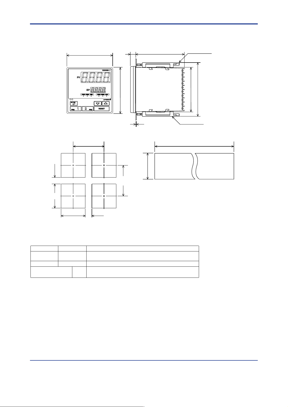
■ External Dimensions and Panel Cutout Dimension
10
UP350
(53)
+0.8
92
0
96
96
11
100
Large bracket
112
91.8
Small bracket
1 to 10 mm (Panel thickness)
General installation Side-by-side close installation
+0.8
0
145 min.
[(N-1)96+92]117 min.
0
+0.8
92
"N" stands for the number of controllers to be
installed.
However, the measured value applies if N 5.
Unit: mm
92
+0.8
0
(25)
■Model and Suffix Codes
Model Suffix Code Description
UP350
Type -0 Standard type
Optional functions
Program controller (provided with retransmission output and
15 V DC loop power supply as standard)
0 None
1 With communication
Standard accessories: Brackets (mounting hardware), unit label, User’s Manuals, and User’s Manual (reference) (CD-ROM
version).
■Items to be specified when ordering
Model and suffix codes, necessary/unnecessary of User’s Manual or QIC.
All Rights Reserved. Copyright © 2000, Y okogawa M&C Corporation
GS 05E01D02-01E 1st Edition Mar.31, 2000-00
 Loading...