

Page 1

User ’s
Manual
UM33A/S006
Digital Indicator with Alarms
(with RS485 Communication Function
(Modbus Master/Monitor))
n
u
F
a
h
n
E
User’s Manual
IM UM33A-01EN-S6
<Detailed Instructions>
l
a
n
tio
c
t
n
e
m
e
c
n
IM UM33A-01EN-S6
1st Edition
Page 2
Model Optional suffix code Descrip tion
UM33A
Digital Indicator with Alarms (Power supply 100-240 V AC)
(provided with retransmission output or 15 V DC loop power
supply, 2 DIs, and 3 DOs)
Type 1 (Basic) -0 Standard type
1 (Note 1 )
1 additional DO (c-contact) and RS485 communication (Max.38.4
kbps, 2-wire/4-wire)
0 NONE
-0 English (degC)
-1 English (deg C& deg F)
0 White (Light gray)
1 Black (Light charcoal gray)
/LP 24 V DC loop power supply
/DC Power supply 24 V AC/DC
/CT (Note 2) Coating
/CV Terminal cover
/S006
RS485 communication (Max.38.4 kbps, 2-wire/4-wire)
MODBUS RTU Master/Moniter
Display language
TOKUCHU
Suffix code
Type 2 (Functions)
Type 3 (Open networks)
Case color
LPS option
Power supply option
Additional treatment option
Terminal Cover
Communication
Modbus
1 Introduction
1.1 Overview
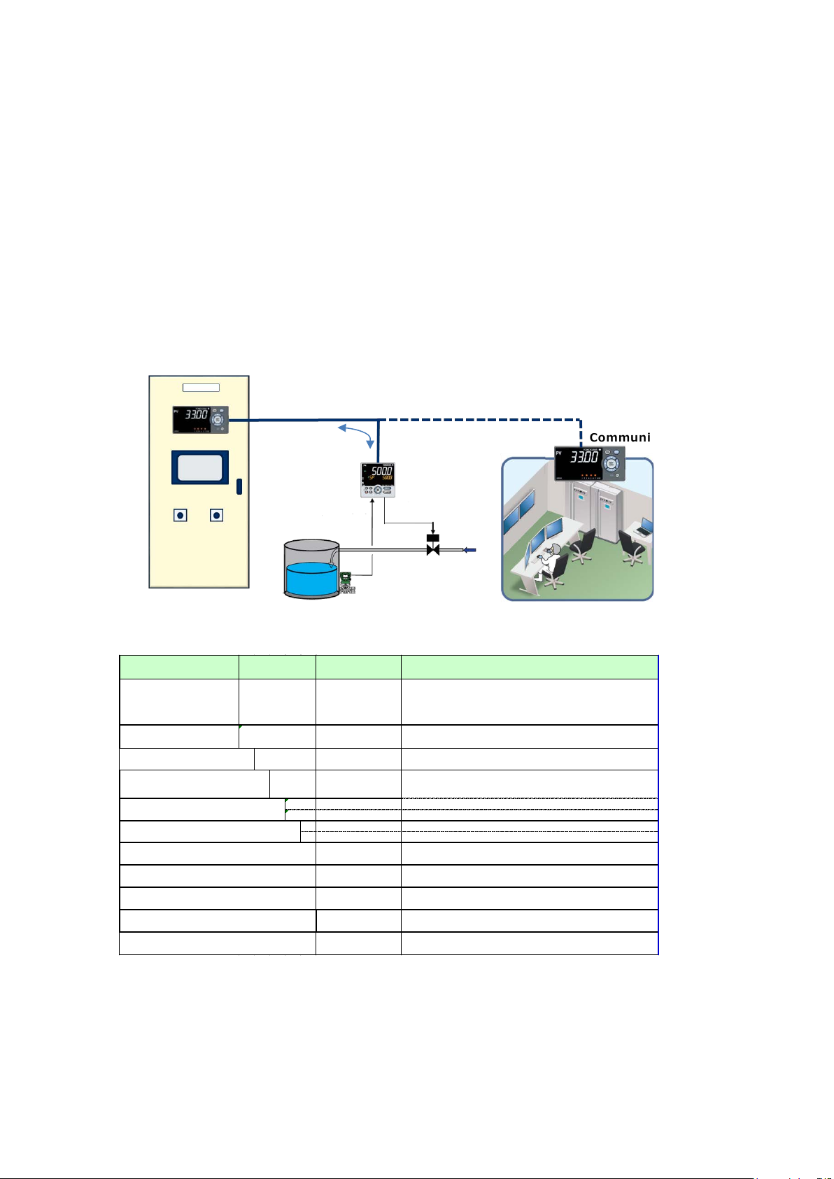
The following two func tions are inco rporated into th e UM33A/S0 06.
• Modbus/RTU master functi on (read only)
• Modbus/RTU communication data monitor function
The M odbus/RTU master func tion allows th e registers of M odbus slave devic es on the same c ircuit
line to be read out. The Modbus/RTU commun ication data monitor function allows communication
between a Modbus mast er and slaves to be m onitored and the res ponse values of the s laves to be
displayed.
This instruction manu al d esc ri bes the dif fere nce b etwe e n this TOKUCHU model and standard model.
Before reading this d ocument, please read the instruction manual of standard model (document
number: IM 05P03D21-01EN)
Modbus slave
2 Model and Suffix Code
UM33A-010-□□/□/S006
□: Specified when ordering
Note 1: When the /LP option is specified, the RS-485 communication of the Type 2 code “1” is 2-wire
system.
Note 2: When the /CT op tion is specified, the product does not co nform to the safety standards ( UL and
CSA) or CE marking (Prod ucts with /CT op tion are not intended for E EA-market).
1
Page 3
Modbus master functi on
Description
Notes
Read
Allowed
Write
Not allowed
Maximum number of com mands
8
8 maximum also
for displays
Supported function cod es
01 (Coil: 1 to 9999)
04 (Input Resister: 30001 to 39999)
Supported data types
Bit
FLOAT
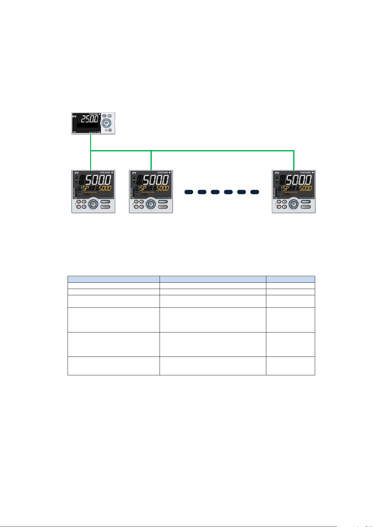
Maximum number of slave devic es
that can be connected on the
same circuit line
31
VOLt
Up to 31 connected slaves with a maximum length of 1200 m
Slave Slave
Master
Slave
3 UM33A Modbus/RTU Master Function, Communication
Data Monitor Function
3.1 Modbus/RTU Master Function
This TOKUCHU product has a Modbus/RTU master function. The Modbus/RTU master function allows
the registers of s lave devices on the same circuit line to be read out and displayed on th e UM33A
screen.
From the master side, Modbus Coil, Discrete Inputs, Holding Resister, and Input Resister can be read
out. The supported Modbus/RTU function codes are 01 (Coil), 02 (Discrete Inputs), 03(Holding
Resister), and 04 (Inp ut Resister). Th e maximum numbe r of read commands and displa ys is eight.
02 (Discrete Inputs: 10001 to 19999)
03 (Holding Resister: 40001 to 49999)
16 bit integer (sign ed only)
32 bit integer (sign ed only)
2
Page 4
3.2 Modbus/RTU Communication Data Monitor Function
Modbus communication data
monitor function
Description
Notes
Read command support
Allowed
Write command support
Not allowed
Maximum number of com mands
8
8 maximum also
for displays
Supported function cod es
01 (Coil: 1 to 9999)
04(Input Resister : 30001 to 39999)
Supported data types
Bit
FLOAT
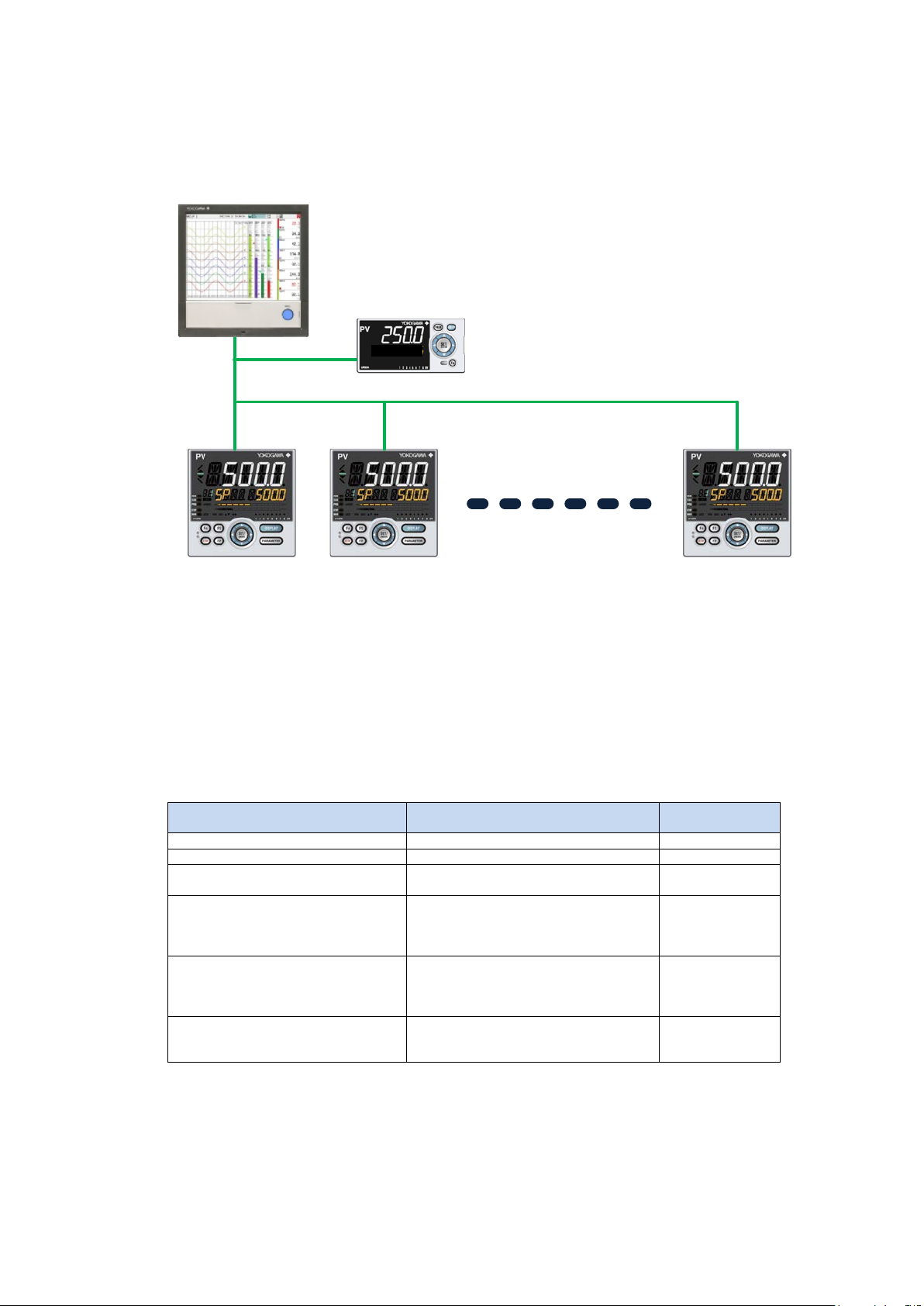
Maximum number of devices that
can be connected on the same
circuit line
The total number of Modbus slave
devices and Modbus communication
data monitors is 3 1.
VOLt
Slave Slave
Monitor
Slave
Master
Up to 31 connected slaves and monitor with a maximum length of 1200 m
This TOKUCHU product has a Modbus/ RTU communication data monit or function. The Modb us/RTU
communication data monitor function allows the monitoring of register readout communication
between a Modbus/RTU master and slave devices on the same circuit line. This function allows
communication respo nse values transmitted on the same circuit line to be displayed on the UM 33A
screen without the U M33A sending c ommunicati on commands.
Communication to Modbus Coil, Discrete Inputs, Holding Resister, and Input Resister can be
monitored. The supported Modbus/RTU function codes are 01 (Coil), 02 (Discrete Inputs),
03(Holding Resister), and 04 (Input Resister). The maximum number of read commands and displays
is eight.
For the continuous read out co mmands s ent from the M odbus master s ide t o the sla ve side , the first
setting parameter length of data (16 bits (1 register) for the Bit and 16 bit integer data types and 32
bits (2 registers) for the 32 bit in teger and F LOAT data types) can be obtained .
02(Discrete Inputs: 10001 to 19999)
03(Holding Resister : 40001 to 49999)
16 bit integer (sign ed only)
32 bit integer (sign ed only)
3
Page 5
3.3 Communication Conditions
○ Connected devices
Up to 31 devices equip ped with M odbus RTU communicatio n function ca n be connect ed.
○ Restrictions on connected devices
The communication conditions, namely the baud rate, parity, stop bit, and data length, of connected
devices must be the s ame as those o f this instru ment.
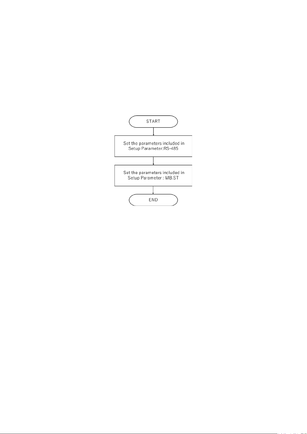
3.4 Simple flow for using Mod bus RTU M aster/Monito r
3.5 Display Erro r of Co mmunic ation P V
For the FLOAT data type, the display error of c ommunicati on PV is ± 1 digit.
4
Page 6

3.6 Data Types Supported by Communication PV and Display
Decimal
Low limit
High limit
BIT
16 bit integer
32 bit integer
FLOAT
decimal point
is selected)
0
-19999
99999
High limit: 1
High limit:
-19999
High limit:
-19999
High limit:
-19999
1
-1999.9
9999.9
High limit: 0.1
High limit:
-1999.9
High limit:
-1999.9
High limit:
-1999.9
2
-199.99
999.99
High limit:
0.00
High limit:
-199.99
High limit:
-199.99
High limit:
-199.99
3
-19.999
99.999
High limit:
0.000
High limit:
-19.999
High limit:
-19.999
High limit:
-19.999
4
-1.9999
9.9999
High limit:
0.0000
High limit:
-1.9999
High limit:
-1.9999
High limit:
-1.9999
Limits
The following table s hows the display l imits for each o f the data typ es suppo rted by c ommu nicat ion
PV. For the FLOAT type, a fixed decimal place display and an auto range display (see section 3.4) are
available. The following table shows the figures for the fixed decimal place . Numbers outside the
-199 99 to 99999 range ig noring the dec imal point are d isplayed as ±OV ER.
Table 3.5.1 Data types supported by communica tion PV and d isplay limits
place
parameter
of
expression
of
expression
display range
Low limit: 0
Low limit: 0.0
0.01
Low limit:
0.001
Low limit:
0.0001
Low limit:
(signed)
display range
32767
Low limit:
3276.7
Low limit:
327.67
Low limit:
32.767
Low limit:
3.2767
Low limit:
(signed)
display range
99999
Low limit:
9999.9
Low limit:
999.99
Low limit:
99.999
Low limit:
9.9999
Low limit:
display range
(when fixed
99999
Low limit:
9999.9
Low limit:
999.99
Low limit:
99.999
Low limit:
9.9999
Low limit:
5
Page 7
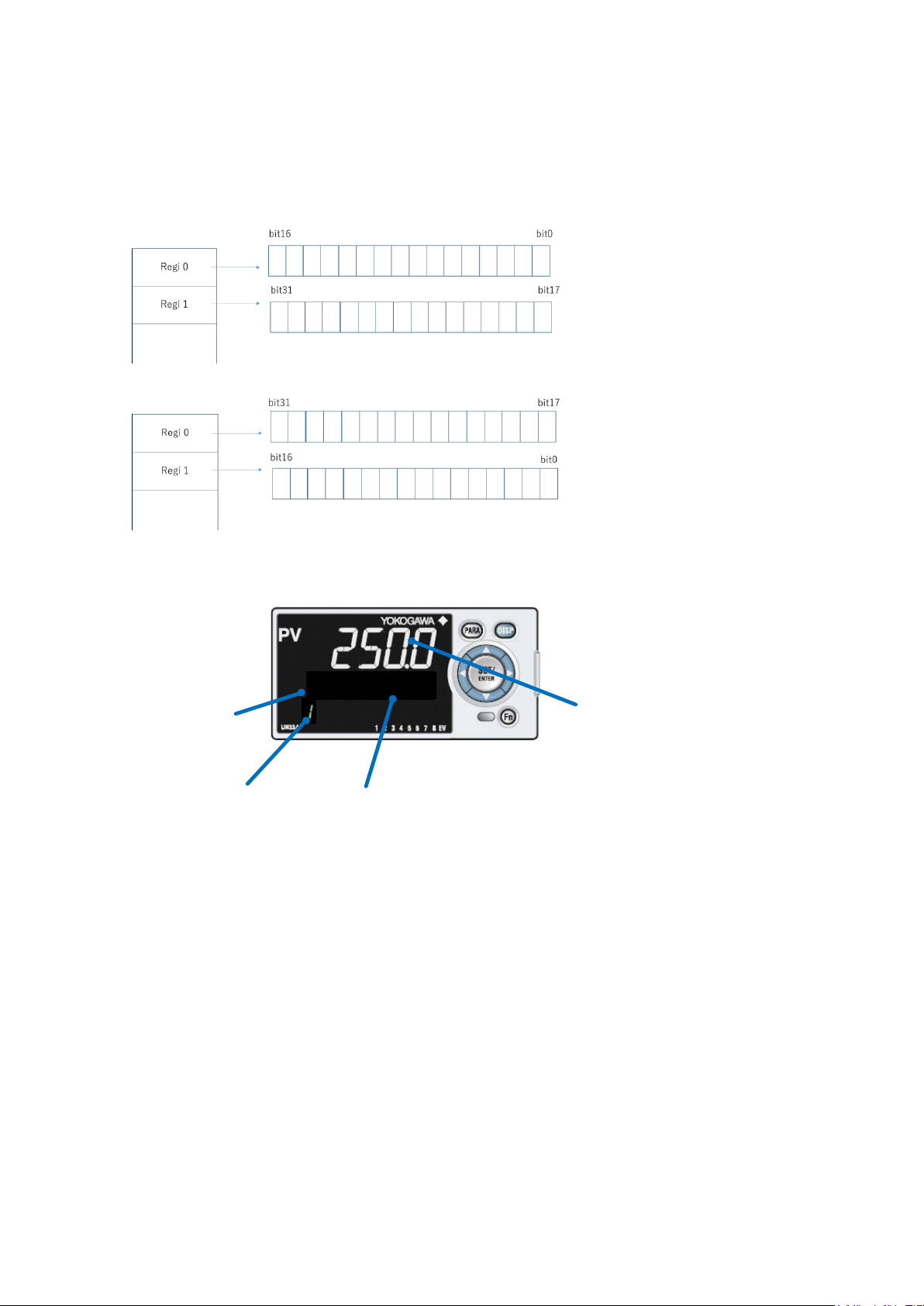
3.7 L-H and H-L Register Arrangements When 32 bit LONG or
k VOLt
Group display
Prefix display
Unit display
Communication
PV display
FLOAT Is Sel ected
For 32 bit integer and FLOAT types, L-H or H-L order can be selected. Set it according to the devices in use.
Figure 3.6.1 32 bit L-H regi ster arran gem ent
Figure 3.6.2 32 bit H-L regi ster ar rangem ent
3.8 Display Screen (Communication PV1 to Communication PV8)
The measured value of the specified register ( MB.ST menu) is dis played. Communic a tion PV number
is shown on the group display. Only when the acquired data type is 16 bit integer, hexadecimal
expression can be us ed by changing FRMT ( MB.ST menu) to HEX.
When the acquired data type is FLOAT and the auto range function is in use, a unit prefix is displayed.
The unit prefix displa y can be switched be tween “T, G, M, k, etc.” and exponential type (E03 , E00,
etc.). Table 3 shows the unit p refix d isplay du ring auto range . If t he value is small er t han ±p (pico)
range when auto range is in u se, “0” is displayed.
6
Page 8

Table 3.7.1 Unit prefix d isplay
Unit display (when un it is selec ted)
Unit display (when ex ponent is s elected)
T (tera)
E12
G (giga)
E09
M (mega)
E06
k (kilo)
E03
No display
E00
ML (milli)
E-03
u (micro)
E-06
N (nano)
E-09
P (pico)
E-12
VOLt
Unit display
Communication
PV display
The unit display show s the selec ted unit (VOLT, A, C, etc.).
The display can be show n or hidden wi th the commun ication ONOFF (MB.ST menu) value.
When the communica tion function ONOFF (MB.ST menu) values are all set to hidde n, only the PV
input is displayed.
If the PV input is hidd en, at leas t one of the ONOF F (MB.ST menu) value is ON.
3.9 Display Sc reen (PV Input)
The PV input is displa yed.
The unit (VOLT, A, C, etc.) is displayed.
The display can be show n or hidden wi th display U.P V (KLOC menu) OFF/ON value.
When the communicati on function ONOFF (M B.ST menu) (1 to 8) values are all set to OFF, the PV
input cannot be hi dden. When any of the commu nication function ONOFF (M B.ST menu) (1 to 8)
values is ON, the PV input c an be hidde n.
7
Page 9

3.10 Auto/Manual Switching of the Op eration Screen
k VOL t
k VOL t
k VOL t
VOL t
k VOL t k VOL t
k VOL t
VOL t
k VOL t
●
1.000
k VOLt
When auto switching of the operation screen is used, the PV input value switches automatically
between communic ation PV1, communicat ion PV2, . . . communica tion PV8 at the spec ified di splay
update interval (3S, 10S, 30S, 1M).
When manual switch ing of the operation screen is used, the PV input value is swi tched between
communication PV1, communication PV2, . . . communication PV8 every time the DISP key is
pressed.
You can switch between auto switchi ng and manual switching using t he Fn key. Switching is also
possible using parame ters.
3.11 Display Screen for Communication Errors
When a communication error occurs, the PV display area of the communication PV1 to
communication PV8 meas urement disp lay operation sc reen blinks .
In addition, if a communic ation error occ urs in any of the communic ation PVs ( PV1 to PV8), the EV
lamp 8 lights.
When a communicatio n error occur s, the previo usly acquire d value is displayed .
Note: On the standard U M33A, the decimal point b links when a communicati on error occurs. This
feature is not available on t his TOKUCHU product .
8
Page 10

3.12 Retransmission Output
Retransmission output can be produced using 4-20mA by selecting PV, communication PV1 to
communication PV8.
The high and low limits of the scale are as follows:
○ When RTS=PV: RTL + 1 digit to 30000
○ When RTS=C.PV: RTL + 1 digit to 99999
previously saved value.
Note: The communicat ion PV retransmis sion outpu t continues produce the sel ected communic ation
PV even when the operatio n screen is cha nged.
Note: Note that if the span exceeds 49999, the resolution of the retransmission output will
decrease.
Note: If the auto range function is enabled when FLOAT is in use, do not use the
retransmission output function.
Note: The re transmission o utput will be un der 4mA until the commun ication establishes
because the initial value of communic ation PV is set to -19999 at Power ON.
-19999 to RTH-1digit
The decimal place is the same as that of the PV input.
(This is the same as the stand ard UM33A.)
-19999 to RTH-1digit
The decimal place is the same as that of SDP in M B.NT.
The setting range is the sa me also for F LOAT.
If communication is disconnected, retransmission output produces the
9
Page 11

3.13 Alarms and Event Lamps
Item
PV
Communication PV
Number of alarms
4
2
Type of alarm
Not set (0)
FAIL(31)
Not set (0)
Standby
Allowed
Not allowed
Energize/De-energize
Allowed
Allowed
Latch
Allowed
Not allowed
PV velocity alarm time s etpoint
Allowed
Not allowed
Hysteresis
Allowed
Allowed
On-delay t imer
Allowed
Not allowed
Off-delay timer
Allowed
Not allowed
VOLt
Event lamp
1~4
PV alarm
display
Event lamp
8
Communication
Error display
Event lamp
5~6
Communication
PV alarm
display
The number of alarms is d ifferent between PV s and commun ication PVs.
PV: 4 alarms
Communication PV: 2 alarms ( can be set onl y for a single co mmunication P V)
Event lamps EV1 to 4 are for PV alarms. EV5 and 6 are for communica tion PV alarms. EV8 is for
communication error indic ations. Thes e indicat ions are fixed. T hey cannot be c hanged.
Event lamps do not cha nge their i ndications e ven when the ope ration screen is d ifferent.
The indications are fixed as follows:
Note: If the auto range function is enabled when FLOAT is in use, do not use the
communication PV alarm s.
Table 3.12.1 Alarm function
PV high limit (1)
PV low limit (2)
PV vel oci ty (2 9)
Self-diagnostics (30)
PV high limit (1)
PV low limit (2)
The required informa tion can be output to DO by setting I relay number to AL1.S to AL4.S (see
“Setting Contact O utput Function” in the standa rd UM33A IM) . Table 3.12.2 show s the additiona l I
relays.
10
Page 12

Figure 3.12.1 Block diagram of the alarm peripheral circuit
I relay number
Description
Notes
4641
Communication PV1 alarm 1 value
4642
Communication PV1 alarm 2 value
4643
Communication PV2 alarm 1 value
4644
Communication PV2 alarm 2 value
4645
Communication PV3 alarm 1 value
4646
Communication PV3 alarm 2 value
4647
Communication PV4 alarm 1 value
4648
Communication PV4 alarm 2 value
4649
Communication PV5 alarm 1 value
4650
Communication PV5 alarm 2 value
4651
Communication PV6 alarm 1 value
4652
Communication PV6 alarm 2 value
4653
Communication PV7 alarm 1 value
4654
Communication PV7 alarm 2 value
4655
Communication PV8 alarm 1 value
4656
Communication PV8 alarm 2 value
4657
Communication erro r
Logic OR of communic ation 1 to 8 er rors
(Handled as no error w hen not in use)
Table 3.12.2 I relays for c ommunicati on PV alarms and c ommunica tion error
11
Page 13

3.14 Deleted Func tions
PV area display
Error description
Handling
PV area blinking
Communication error
Check the communication settings
and wiring.
NAN
When the FLOAT data type is
number, ±infinity, or denormalized
number.
Check whether the data type of
The following ten functions ha ve been delet ed from this TOKU CHU product.
• PV alarms 5 to 8 are not available. The only available PV alarms are 1 to 4.
• RS485 PC link communication, ladder communication, Modbus (ASCII) slave, Modbus (RTU) slave
communication protoc ols are not availab le.
• Quick setting mode is not available.
• The function for chang ing the event d isplay is not available.
• The decimal point blinking for communication errors is not available. See section 3.10, “Display Screen for
Communication Error s.”
• Guide display is availab le only in E nglish. Other languages ar e not supported .
•SELECT Display.
•Function key function o f standa rd model.
• Guide Display ON/OF F function (parame ter or Fn Key) is not availab le.
•PV peak and bottom value d isplay function .
3.15 Troubleshooting
selected, t he readout value is not a
3.16 LL50A
Parameter Setting Software L L50A cannot be used.
the connec ted re gister is in teger.
Check the connected device error.
12
Page 14

Function setting m enu (menu: CTL)
Parameter sym bol Name of parameter Disp lay level Setting range Initial value
ALNO. Numb er of alarms PRO 0 to 4 4
ALSL
Commun ication PV al arm sel ection STD
C.PV1: U se communi cation PV1 for th e commu nicati on alarm
C.PV2: U se communi cation PV2 for th e commu nicati on alarm
C.PV3: U se communi cation PV3 for th e commu nicati on alarm
C.PV4: U se communi cation PV4 for th e commu nicati on alarm
C.PV5: U se communi cation PV5 for th e commu nicati on alarm
C.PV6: U se communi cation PV6 for th e commu nicati on alarm
C.PV7: U se communi cation PV7 for th e commu nicati on alarm
C.PV8: U se communi cation PV8 for th e commu nicati on alarm
C.PV1
Input ra nge set ting menu (menu: MPV)
Parameter sym bol Name of parameter Dis play level Setting ran ge Initial value
M.UNI
Analog operation s creen disp lay uni t STD
-: no units
VOLT: voltage
A: cu rrent
%: %
C: Celsius
F:Fahrenheit
ppm: concentration
PSCL: p ressure,
KPACL: p ressure,
MPACL: pres sure
pH: hydrogen ion exponent
l: volume
m3/s: flow rate- m3/s
m3/m: flow rate-m3/min,
m3/h: flow rate- m3/hr
l/s: flow rate- l/s
l/min: flow rate-l/min
l/h: flow rate- l/hr
-: no units
Output set ting menu (menu: OUT)
Parameter sym bol Name of parameter D
isplay level Settin g range Initial value
RTS RET retransmis sion output type EASY
OFF: Not set
PV: PV
L
PS: 15 V DC loop pow er suppl y
C.PV1: Communication PV1
C.PV2: Communication PV2
C.PV3: Communication PV3
C.PV4: Communication PV4
C.PV5: Communication PV5
C.PV6: Communication PV6
C.PV7: Communication PV7
C.PV8: Communication PV8
PV
RTH
RET retransmis sion output scale
maximum
STD 100% of PV input ran ge
RTL
RET retransmis sion output scale
minimum
STD 0% of PV input range
When RTS=PV,
RTL+1 di git to 30000
-
19999 to RTH-1 digit
The dec imal place wh en RTS=PV is the same as that for PV
input.
When RTS=C.PV,
RTL+1 di git to 99999
-19999 to RTH- 1digit
The dec imal place is the same as that of SDP in MB.ST.
The setti ng range is the s ame for Float.
4 Setting Para meters
The following tables show the setting parameters.
4.1 Parameters
The additional parame ters on this TOKUCHU product are sh own below.
[Setup Parameters]
13
Page 15

※WAIT, RTRY, RVV are effecti ve when UM 33A is Mo dbus RTU Ma ster.
RS-485 communication set ting me nu (menu: R485)
Parameter sym bol Name of parameter Dis play level Setting range Initial value
PSL
Protocol s election EASY
MSMST : Modbus Master
MSMNT : M odbus Mon itor
MSMST
BPS Baud rate EASY
9600: 9600 bps
19200: 19.2k bp s
38400: 38.4k bp s
19200
DLN
Data length EASY 8:8 bits 8
INT Modb us mas ter interval EA SY 100 to 2000 (ms) 500
TMO Modb us mas ter timeout EASY 100 to 1000 (ms) 100
WAIT Modb us mas ter gap between messages EASY
OFF : OFF
10 : 10ms
20 : 20ms
50 : 50ms
100 : 100ms
OFF
RTRY Modb us mas ter retry count EASY
OFF: OFF
1: Once
2: Twic e
3: Three times
4: Four ti mes
5: Five times
OFF
RVV Modbus m aster connection recovery wait EASY OFF (0): Dis abled, 1 to 120 s OFF
Setting menu (m enu: MB.ST)
Parameter sym bol Name of paramet er Dis play level Setting ran ge Initial value
ONOF Master, monitor func tion on/off EASY
OFF: Function disabled (not shown on the operation screen)
ON: Function enabled (shown on the operation screen)
OFF
ADR Slave addres s EASY 1~247 1
DATA Read data type EASY
BIT: BIT
SHRT: 16 bit i nteger (signed )
L
NG.LH : 32 bit integer (signed) lower 16 bit -> upper 16 bit
order
LNG.HL : 32 bit integer (signed) upper 16 bit -> lower 16 bit
order
FLT.LH: 32 bit floating point lower 16 bit -> upper 16 bit
order
FLT.HL: 32 bit floating point upper 16 bit -> lower 16 bit
order
SHRT
REG Read device register nu mber E
ASY
1 to 19999 (Bit),
30001 to 49999(SHRT, LNG, FLT)
40001
SDP Dec imal place E
ASY 0 to 4 1
DP.CG Float type au to range on/off E
ASY
FIX: Fixed decimal poi nt
AUTO: Auto range
FIX
PR.UN PV in put unit prefix selection STD
0: T, G, M, k and other unit prefix notation
1: Exponential notation
0
P.UNI Operation screen disp lay unit S
TD
-: no units
VOLT: voltage
A
: curren t
%: %
C: Celsius
F:Fahrenheit
ppm: concentration
PSCL: p ressure,
KPACL: p ressure,
MPACL: pres sure
pH: hydrogen ion exponent
l: volu me
m3/s: flow rate- m3/s
m3/m: flow rate-m3/min,
m3/h: flow rate- m3/hr
l/s: flow rate- l/s
l/min: flow rate-l/min
l/h: flow rate- l/hr
-: no units
FRMT
Decimal /hexadecimal d isplay STD
DEC: Decim al
HEX: Hexad ecimal
DEC
* The sam e settin g appli es to group 1 to 8.
※When RVV=OFF(0), once a communication error occurs, it will not automatically
reconnect. To reconnect, turn on the p ower aga in or set the setting value of RVV
to other than OFF(0).
14
Page 16

Note1: When the communication function ONOFF (MB.ST menu) values are all set to hidden, only the
Setting menu (m enu: MB.DP)
Parameter sym bol Name of parameter Disp lay level Setting range Initial value
AT.SC
Autom atic s witc h to program operation
display
EASY
OFF: Automatic switch to program op eration disp lay
disabled
ON: Au tomatic s witch to program operation d isplay enab led
OFF
D.CYC
Autom atic s witc h to program operation
display refresh time
STD
3 : 3s
10 : 10s
30 : 30 s
60 : 60s
3
Menu lock se tting menu (me nu: MLOC)
Parameter sym bol Name of parameter D ispl ay level Setting ran ge Initial value
MB.ST
MB.ST menu loc k PRO OFF
MB.DP MB.DP m enu lock P
RO OFF
M.ALM
M.ALM menu lock PRO O
FF
OFF:Display
ON:Nondis play
System sett ing menu (menu: SYS)
Parameter sym bol Name of parameter Display level Setting ran ge Initial value
LANG G uide dis play lan guage EASY ENG: En glish
Depend s on the model and
suffix codes
Error/version confirmation menu (menu: VER)
Parameter symbol Name of parameter Dis play level Display only
A.STS Communication PV alarm status EASY
The on/off state of alarms assign ed to each bit is displayed
in hexadecimal notation. However, only assign ed
communi cation PVs will be set to on or off.
Bit 0: Communication PV1 alarm 1 status
B
it 1: Communication PV1 alarm 2 status
Bit 2: Communication PV2 alarm 1 status
Bit 3: Communication PV2 alarm 2 status
Bit 4: Communication PV3 alarm 1 status
Bit 5: Communication PV3 alarm 2 status
Bit 6: Communication PV4 alarm 1 status
Bit 7: Communication PV4 alarm 2 status
Bit 8: Communication PV5 alarm 1 status
Bit 9: Communication PV5 alarm 2 status
Bit 10: Communication PV6 alarm 1 status
Bit 11: Communication PV6 alarm 2 status
Bit 12: Communication PV7 alarm 1 status
Bit 13: Communication PV7 alarm 2 status
Bit 14: Communication PV8 alarm 1 status
Bit 15: Communication PV8 alarm 2 status
P.STS Communication error status EASY
0x0001: Communication error present
0x0000: Communication error absent
PV input is displayed.
If the PV input is hidd en, at leas t one of the ONOF F (MB.ST menu) value is ON.
Note2: The display ca n be shown or hid den with disp lay U.PV (KLOC menu) OFF/ON value.
When the communicati on function ONOFF (M B.ST menu) (1 to 8) values are all set to OFF, the PV
input cannot be hi dden. When any of the commu nication function ONOFF (M B.ST menu) (1 to 8)
values is ON, the PV input c an be hidde n.
Note: The following e xample des cribes how the A .STS displa y works.
Example: When commu nication PV1 alarm 1 status is ON, this expressed i n binary is 0000 0000
0000 0001, which is 0x0001 in hexadecimal notation.
When communication PV1 alarm 1 and 2 statuses are ON, this expressed in binary is 0000 0000
0000 0011, which is 0x0003 in hexadecimal notation.
15
Page 17

Comm unication PV ala rm function set ting me nu (menu: M.ALM)
Parameter sym bol Name of parameter Dis play level Setti ng range Initial value
AL1.T to A L2.T Commun ication PV al arm type 1 an d 2 EASY
0: Not set
1: PV high limit
2: PV low limit
PV high limit: 1 (AL1.T)
PV low limit: 2 (AL2.T)
AL1.D to A L2.D
Commun ication PV al arm energi ze/deenergize 1 an d 2
EASY
0: Energi ze
1: De-energize
0
M.HY1 to M.HY2
Commun ication PV al arm hys teresis 1
and 2
EASY -19999 to 99999 10
MB.A1 to MB.A2
Commun ication PV al arm setp oint 1 and
2
EASY -19999 to 99999 0
PV1 to PV 8 can be set.
[Operation Parameters]
16
Page 18

PASS CTL PV MPV OUT R485 MB.ST
ALNO. IN P.UNI RTS PSL ONOF ONOF ONOF ONOF ONOF ONOF ONOF ONOF
SMP UNIT P.DP RTH BPS ADR ADR ADR ADR ADR ADR A DR ADR
ALSL RH P.RH RTL PRI DATA DATA DATA DATA DATA DATA DA TA DATA
END RL P.RL RET.H STP REG REG REG REG REG REG REG REG
SDP M.UNI RET.L DLN SDP SDP SDP SDP SD P SDP SD P SDP
SH END RET.A ADR DP.CG DP.CG DP.CG DP.CG DP.CG DP.CG DP.CG DP.CG
SL END RP .T PR.UN PR.UN PR.UN PR.UN PR.UN PR.UN PR.UN PR.UN
BSL INT P .UNI P.UNI P .UNI P.UNI P. UNI P.UNI P. UNI P.UNI
RJC TMO FRMT FRMT FRMT FRMT FRMT FRMT FRMT FRMT
ERJC WAIT END END END END END END END END
A.BS RTRY
A.FL RVV
A.SR END
A.LC
END
P
S
S
S
S
P
P
P
S
S
S
S
P
P
P
S
P
S
S
S
S
S
S
S
S
S
S
S
S
S
S
S
S
S
S
S
S
S
S
S
S
S
S
S
S
S
MB.DP KEY DISP CSEL KLO C MLOC DI.SL DI.D ALM I/O SY S INIT VER LVL END PASS
AT.SC Fn PCMD CS1 U
.PV CTL RST DI1.D AL1.S KEY R.TM U.DEF PA.ER LEVL
D.CYC END PCH CS2 COM.W PV LAT DI2.D AL2. S X000 C.GRN F.DEF OP. ER
END PCL CS3 DATA MPV LCD END AL3.S Y 000 FREQ END AD1.E
EV1 CS4 END OUT PVRW AL4.S Y100(E1) QSM PV1.E
EV2 CS5 R485(E1) MG1 AL 1.D END LANG MCU
EV3 END CC- L(E1) MG2 AL2.D PASS DCU
EV4 MB.ST MG3 A L3.D END ECU1(E 1)
EV5 MB.DP MG4 AL4.D PARA
EV6 KEY END END H.VER
EV7 DISP SER1
EV8 CSEL SER2
PV.D KLOC A.STS
SP.D DI.SL P.STS
STS.D DI.D END
SPD ALM
GUID DO(E1)
HOME I/O
ECO SYS
BRI INIT
B.PVW V ER
B.PVR LVL
B.SP AL
B.STS ALRM
D.CYC M.ALM
OP.JP PVS
MLSD PY S1
MKTP PYS2
END END
S
S
P
P
S
S
S
S
S
S
P
PPP
P
P
S
S
S
S
P
P
P
P
P
P
S
S
P
P
P
P
P
P
P
P
S
S
S
S
P
S
P
P
4.2 Parameter Map
[Setup Parameters]
Parameters added in this TOKUCHU product are indicated in yellow.
Parameters deleted from this TOKUCHU product a re indicated in gray.
17
Page 19

[Operation Parameters]
AL ALRM M.ALM PVS PYS1 PYS2 END AL
A1 AL1 AL1.T AL1.T A L1.T A L1.T AL1.T A L1.T AL1. T AL 1.T BS A1(1) A1(2)
A2 AL2 AL2.T AL2.T A L2.T A L2.T AL2.T A L2.T AL2. T AL 2.T FL B1( 1) B1( 2)
A3 AL3 AL1.D AL1.D AL1.D AL1.D AL1.D AL1.D AL1.D AL1.D PEAK A2(1) A 2(2)
A4 AL4 AL2.D AL2.D AL2.D AL2.D AL2.D AL2.D AL2.D AL2.D BOTM B2( 1) B2( 2)
A5 AL5 M.HY 1 M.HY1 M.HY1 M.HY1 M .HY1 M.HY1 M.HY1 M.HY1 END A3(1) A3( 2)
A6 AL6 M.HY 2 M.HY2 M.HY2 M.HY2 M .HY2 M.HY2 M.HY2 M.HY2 B3(1) B3( 2)
A7 AL7 MB.A1 MB.A1 MB.A1 MB.A1 MB.A 1 MB.A 1 MB.A 1 MB.A1 A4(1) A 4(2)
A8 AL8 MB.A2 MB.A2 MB.A2 MB.A2 MB.A 2 MB.A 2 MB.A 2 MB.A2 B4(1) B4(2)
END VT1 END END END END END EN D END END A5(1) A5(2)
VT2 B5(1) B5( 2)
VT3 A6(1) A 6(2)
VT4 B6(1) B6( 2)
VT5 A7(1) A 7(2)
VT6 B7(1) B7( 2)
VT7 A8(1) A 8(2)
VT8 B8(1) B8( 2)
HY1 A9(1) A9(2)
HY2 B9(1) B9(2)
HY3 A10(1) A10(2)
HY4 B10(1) B10(2)
HY5 A11(1) A11(2)
HY6 B11(1) B11(2)
HY7 PMD PMD
HY8
DYN1
DYN2
DYN3
DYN4
DYN5
DYN6
DYN7
DYN8
DYF1
DYF2
DYF3
DYF4
DYF5
DYF6
DYF7
DYF8
END END END
P
P
P
S
S
S
S
S
S
S
S
P
P
P
P
P
P
P
Parameters added in this TOKUCHU product are indicated in yellow.
Parameters deleted from this TOKUCHU product are indicated in gray.
18
Page 20

5 Wiring the RS485 Commu nication Interface
To perform Modbus Master/Monitor communication, wire the system as shown below. Attach a terminator to
the device at the end of the cir cuit.
Modbus Master 4-wire system wiring
2- wire system wiring of Modbus Master 4-wire system terminals
Wiring of Modbus Master 4- wire system terminals and 2- wire system terminals
19
Page 21

Modbus Master -wire system wiring (/LP option only)
4- wire system wiring of Modbus Monitor 4-wire system terminals
20
Page 22

2- wire system wiring of Modbus Monitor 4-wire system terminals
2- wire system wiring of Modbus Monitor 2-wire system terminals (/LP option only)
21
 Loading...