

Page 1

User’s
Manual
Models UM351/UM331
Digital Indicator with Alarms
User’s Manual
IM 05F01D12-41E
IM 05F01D12-41E
4th Edition
Page 2

Blank Page
Page 3
<Toc> <Rev>
Introduction
Thank you for purchasing the UM351/UM331 digital indicator with alarms.
■ How to Use the Manuals
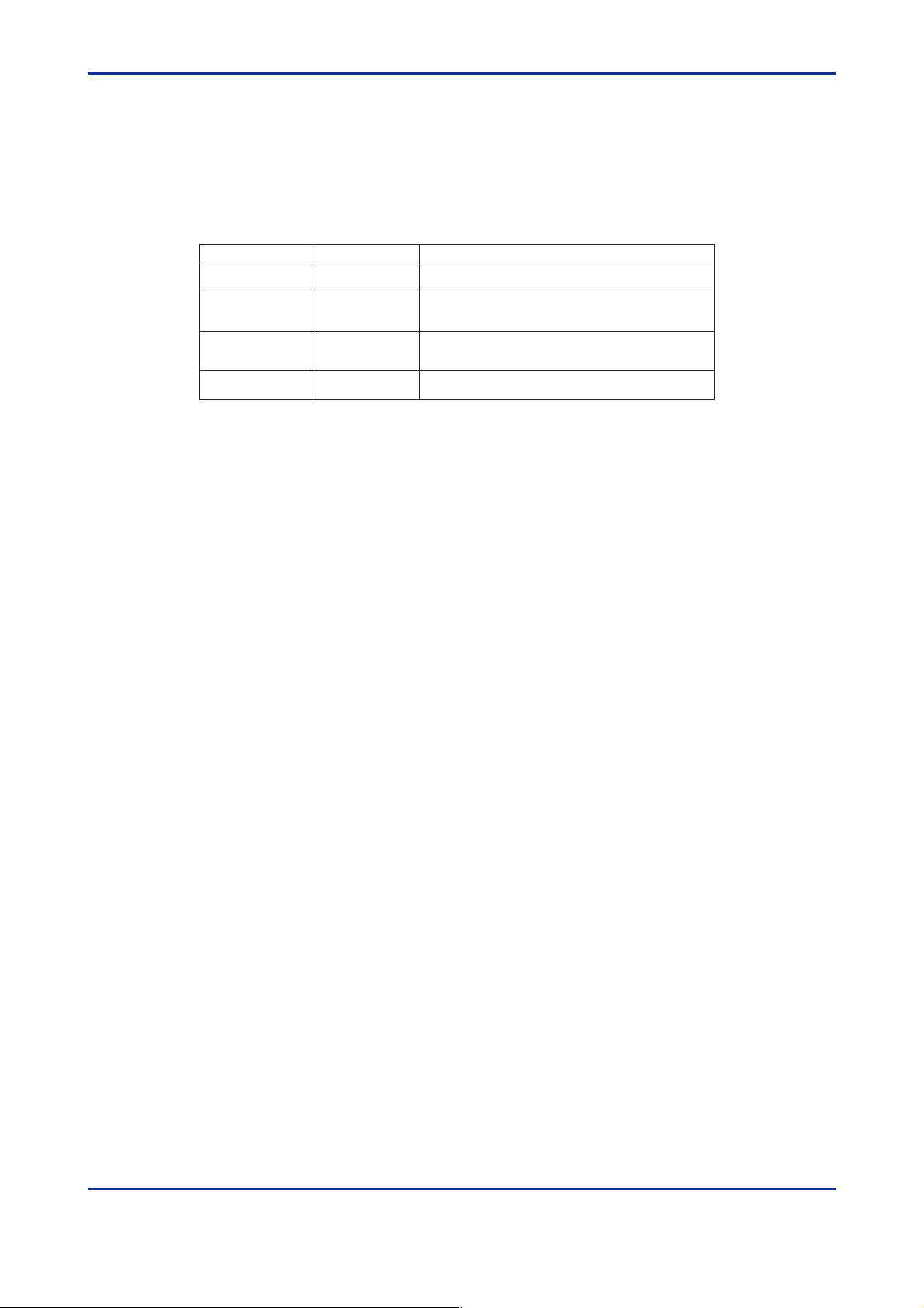
Purpose Title Description
1. Installation
2.
Initial Settings
3. Operations
4.1 Troubleshooting
5. Parameters
Setup Describes the tasks (installation, wiring, and others) required
Basic operation
Operating
procedures
and troubleshooting
Brief operation
and setpoint recording
■ Regarding This User’s Manual
(1) This manual should be provided to the end user. Keep an extra copy or copies of the
manual in a safe place.
to make the indicator ready for operations.
Describes examples of setting PV input types, and alarm
types. Making settings described herein allows you to carry
out basic monitoring.
Describes examples of setting alarm setpoints, as well as
key operation necessary to run the indicator.
Contains the parameter map used as a guideline for setting
parameters and lists of parameters for recording user settings.
i
(2) Read this manual carefully to gain a thorough understanding of how to operate this
product before starting operation.
(3) This manual describes the functions of this product. Yokogawa Electric Corporation
(hereinafter simply referred to as Yokogawa) does not guarantee the application of
these functions for any particular purpose.
(4) Under absolutely no circumstances may the contents of this manual, in part or in
whole, be transcribed or copied without permission.
(5) The contents of this manual are subject to change without prior notice.
(6) Every effort has been made to ensure that the details of this manual are accurate.
However, should any errors be found or important information be omitted, please
contact your nearest Yokogawa representative or our sales office.
Media No. IM 05F01D12-41E (CD) 4th Edition : May 2006 (YK)
All Rights Reserved Copyright © 2003, Yokogawa Electric Corporation
IM 05F01D12-41E 4th Edition: May 31, 2006-00
Page 4
<Toc> <Rev>
■ Safety Precautions
The following symbol is indicated on the indicator to ensure safe use.
This symbol on the indicator indicates that the operator must refer to an explanation in the
user’s manual in order to avoid the risk of injury or death of personnel or damage to the
instrument. The manual describes how the operator should exercise special care to avoid
CAUTION
electric shock or other dangers that may result in injury or loss of life.
The following symbols are used in the hardcopy user’s manuals and in the user’s manual
supplied on the CD-ROM.
NOTE
Indicates that operating the hardware or software in a particular manner may damage it or
result in a system failure.
ii
IMPORTANT
Draws attention to information that is essential for understanding the operation and/or
features of the indicator.
■ Force Majeure
(1) Yokogawa assumes no liability to any party for any loss or damage, direct or indirect,
caused by the use or any unpredictable defect of the product.
(2) No portion of the software supplied by Yokogawa may be transferred, exchanged,
leased or sublet for use by any third party without the prior permission of Yokogawa.
(3) Be sure to use the spare parts approved by Yokogawa when replacing parts or
consumables.
(4) Use this software with one specified computer only. You must purchase another copy
of the software for use on each additional computer.
(5) Copying this software for purposes other than backup is strictly prohibited.
(6) Store the floppy disk(s) (original medium or media) containing this software in a
secure place.
IM 05F01D12-41E 4th Edition: May 31, 2006-00
Page 5

<Toc> <Rev>
■ Regarding Protection, Safety, and Prohibition Against Unauthorized
Modification
(1) In order to protect the product and the system controlled by it against damage and
ensure its safe use, make certain that all of the instructions and precautions relating to
safety contained in this document are strictly adhered to. Yokogawa does not guaran-
tee safety if products are not handled according to these instructions.
(2) Modification of the product is strictly prohibited.
(3) Reverse engineering such as the disassembly or decompilation of software is strictly
prohibited.
iii
IM 05F01D12-41E 4th Edition: May 31, 2006-00
Page 6

Blank Page
Page 7

<Int> <Rev>
Models UM351/UM331
Digital Indicator with Alarms
User’s Manual
CONTENTS
Introduction........................................................................................................... i
1. Installation .............................................................................................. 1-1
1.1 Model and Suffix Codes.................................................................................. 1-1
1.2 How to Install................................................................................................... 1-2
1.3 How to Connect Wires .................................................................................... 1-5
1.4 Hardware Specifications ................................................................................ 1-7
1.5 Terminal Wiring Diagrams ............................................................................ 1-12
2. Initial Settings ......................................................................................... 2-1
Toc-i
IM 05F01D12-41E 4th Edition
2.1 Names and Functions of Front Panel Parts................................................... 2-2
2.2 Setting PV Input Type (Setting First at Power-on)......................................... 2-3
2.3 Changing PV Input Type ................................................................................. 2-7
2.4 Changing Alarm Type ..................................................................................... 2-9
2.5 Setting Hysteresis in Alarm Setpoint ............................................................2-11
2.6
2.7 Setting the High Limit and Low limit for PV Color change ......................... 2-13
Setting the PV display color changing function “Active Color PV Display”...
2-12
3. Operations .............................................................................................. 3-1
3.1 Monitoring-purpose Operating Display Available during Operation ........... 3-1
3.2 Setting Alarm Setpoints .................................................................................. 3-2
4. Troubleshooting and Maintenance ........................................................ 4-1
4.1 Troubleshooting.............................................................................................. 4-1
4.2 Maintenance .................................................................................................... 4-4
4.2.1 Cleaning ........................................................................................... 4-4
4.2.2 Replacing Brackets ........................................................................... 4-4
4.2.3 Attaching Terminal Cover .................................................................. 4-4
4.2.4 Replacing Parts with a Limited Service Life ....................................... 4-6
5. Parameters.............................................................................................. 5-1
5.1 Parameter Map ................................................................................................ 5-1
5.2 Lists of Parameters ......................................................................................... 5-2
Revision Information ............................................................................................ i
IM 05F01D12-41E 4th Edition: May 31, 2006-00
Page 8

Blank Page
Page 9
<Toc> <1. Installation>
1. Installation
This chapter describes installation, wiring, and other tasks required to make the
indicator ready for operation.
1.1 Model and Suffix Codes
Before using the indicator, check that the model and suffix codes match your order.
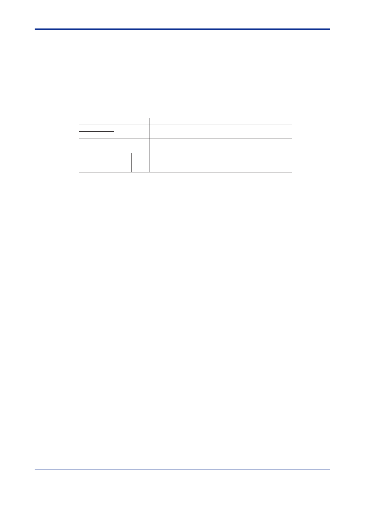
Model Suffix Code Description
UM351
UM331
Type
Optional functions
-0 Standard type with three alarms
-3 Standard type with three alarms (with 24 V DC loop power supply)
Check that the following items are provided:
• Digital indicator with alarms (of ordered model) .................... 1
Digital indicator with Alarms (provided with retransmission output and 15
V DC loop power supply as standard)
0 None
1 With communication and additional alarm-4
2 With additional alarm-4
1-1
• Brackets (mounting hardware) ............................................. 1 pair
• Unit label.............................................................................. 1
• User’s Manuals.................................................................... 3 (A2 size)
• User’s Manuals
“Setting/Explanation of Active Color PV Display ................... 1 (A3 size)
• User’s Manual (Reference) (CD-ROM version)
(only for indicators with optional communication functions)... 1
IM 05F01D12-41E 4th Edition: May 31, 2006-00
Page 10
<Toc> <1. Installation>
1.2 How to Install
NOTE
To install the indicator, select a location where:
1. no one may accidentally touch the terminals,
2. mechanical vibrations are minimal,
3. corrosive gas is minimal,
150 mm
1-2
4. temperature can be maintained at about 23C and
the fluctuation is minimal,
150 mm150 mm
150 mm
5. no direct radiant heat is present,
6. no magnetic disturbances are caused,
7. no wind blows against the terminal board (reference junction compensation element),
8. no water is splashed,
9. no flammable materials are around,
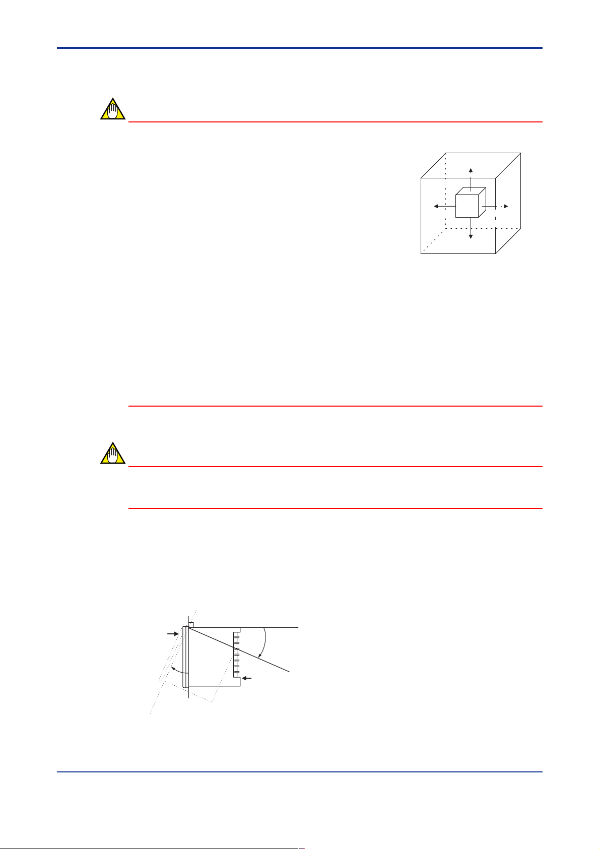
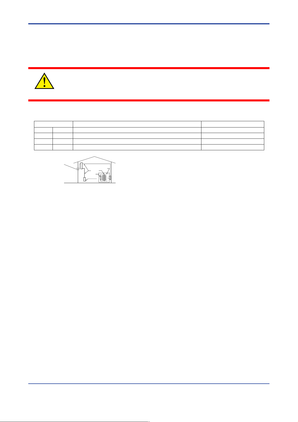
Never place the indicator directly on flammable items or equipment.
If the indicator has to be installed close to flammable items or equipment, be sure to pro-
vide shielding panels all around the indicator, at least 150 mm away from every side; the
panels should be made of either 1.43 mm-thick metal-plated steel plates or 1.6 mm-thick
uncoated steel plates.
NOTE
Never touch the opening at the bottom of the case. It is to be used in the factory at shipping.
● Installation Position
Install the indicator at an angle within 30 from horizontal with the front panel facing upward. Do not install it facing downward. The position of right and left sides should be horizontal.
Front panel
of indicator
30
Must not
exceed 30
Rear of
indicator
IM 05F01D12-41E 4th Edition: May 31, 2006-00
Page 11
<Toc> <1. Installation>
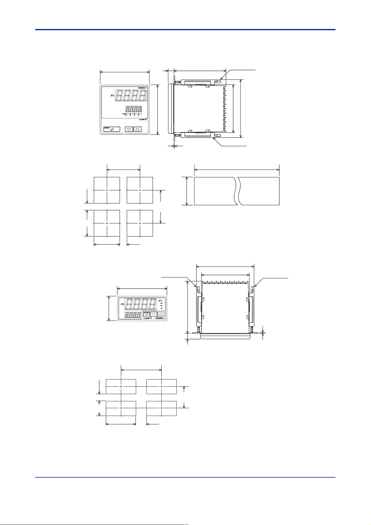
■ External Dimensions and Panel Cutout Dimensions
1-3
UM351
(53)
+0.8
92
0
96
11
96
100
1 to 10 mm (Panel thickness)
Large bracket
112
91.8
Small bracket
General installation Side-by-side close installation
+0.8
0
145 min.
[(N-1)96+92]117 min.
0
+0.8
92
"N" stands for the number of indicators to be
installed.
However, the measured value applies if N 5.
Unit: mm
UM331
45
(25)
+0.6
+0.8
92
0
48
General installation
0
92
+0.8
0
(25)
96
145 min.
Small bracket
(53)
10011
70 min.
112
91.8
Front of indicator
Unit: mm
Small bracket
1 to 10 mm (Panel thickness)
IM 05F01D12-41E 4th Edition: May 31, 2006-00
Page 12
<Toc> <1. Installation>
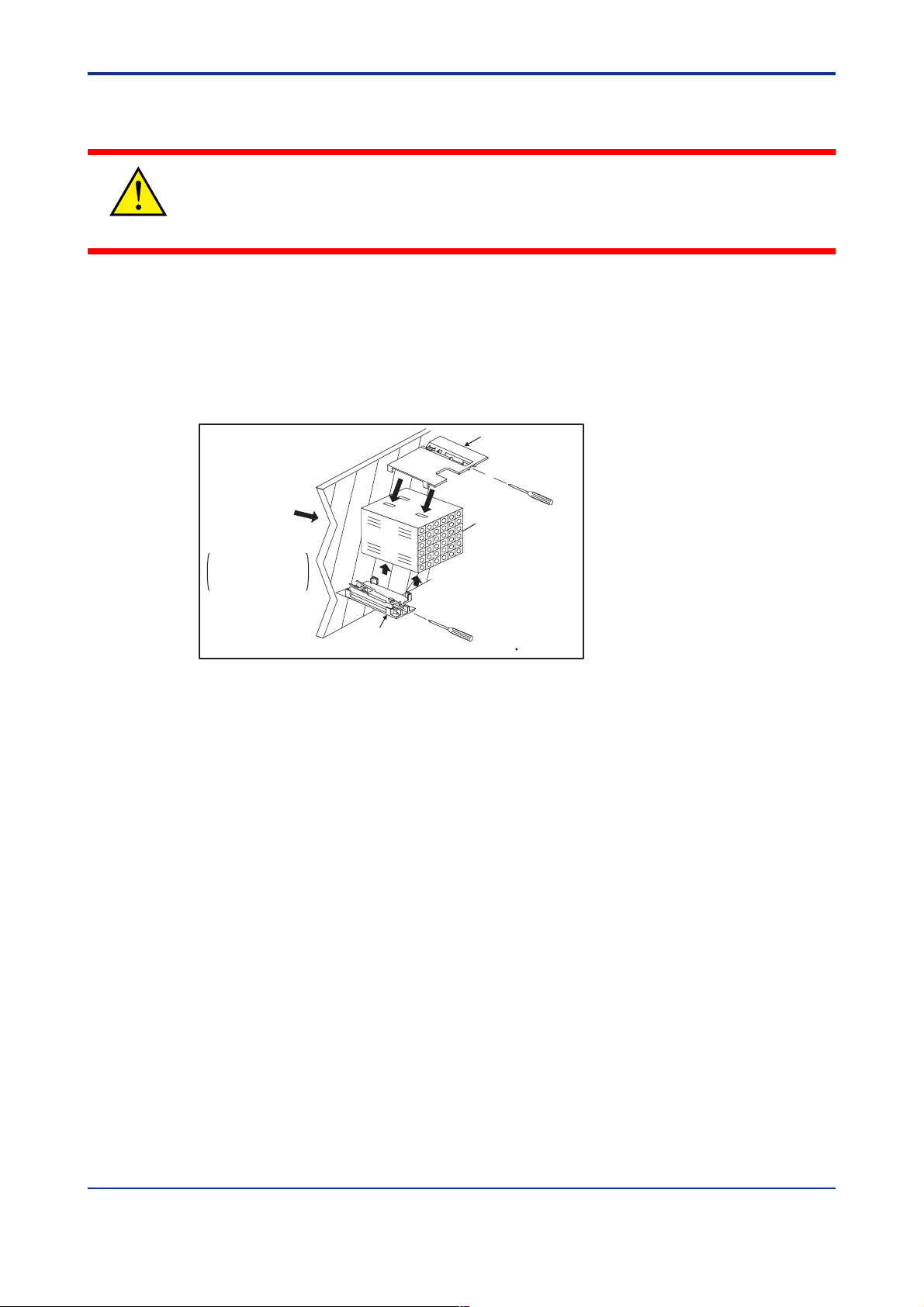
■ How to Install
Turn off the power to the indicator before installing it on the panel because there is a possibility of electric shock.
CAUTION
After opening the mounting hole on the panel, follow the procedures below to install the
indicator:
1. Insert the indicator into the opening from the front of the panel so that the terminal
board on the rear is at the far side.
2. Set the brackets in place on the top and bottom of the indicator as shown in the figure
below, then tighten the screws of the brackets. Take care not to overtighten them.
1-4
Panel
Direction to insert the
indicator
Insert the
indicator
into the opening at
the front of the panel.
Note: Right and left mounting for UM331.
Small bracket
(bottom mounting hardware)
Large bracket
(top mounting hardware)
Terminal board
Insert a screwdriver into the
brackets to tighten the screws.
Recommended
tightening torque
:0.4N m
IM 05F01D12-41E 4th Edition: May 31, 2006-00
Page 13
<Toc> <1. Installation>
1.3 How to Connect Wires
1) Before carrying out wiring, turn off the power to the indicator and check that the cables
to be connected are not alive with a tester or the like because there is a possibility of
electric shock.
CAUTION
2) Wiring must be carried out by personnel who have basic electrical knowledge and
practical experience.
NOTE
1) Provide power from a single-phase instrument power supply. If there is a lot of noise in
the power line, insert an insulating transformer into the primary side of the line and use
a line filter (recommended part: ZAC2205-00U from TDK) on the secondary side.
As a countermeasures against noise, do not place the primary and secondary power
cables close to each other.
2) For thermocouple input, use shielded compensating lead wires for wiring. For RTD
input, use shielded wires that have low conductor resistance and cause no significant
differences in resistance between the three wires.
The cables to be used for wiring, terminal specifications, and recommended parts are
as shown below.
1-5
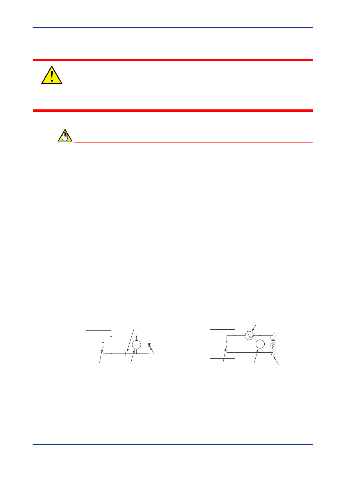
3) Alarm output relays have a life of 100,000 times that of the resistance load, use
auxiliary relays to turn on/off a load.
4) The use of inductance (L) loads such as auxiliary relays, motors and solenoid valves
causes malfunction or relay failure; always insert a CR filter for use with alternating
current or a diode for use with direct current, as a spark-removal surge suppression
circuit, into the line in parallel with the load.
5) When there is possibility of being struck by external lightening surge, use the arrester
to protect the instrument.
■ For DC Relay Wiring ■ For AC Relay Wiring
UM351/UM331
Relay
UM’s contact
(Use one with a relay coil
rating less than the UM’s
Relay
contact rating.)
External DC power supply
R
Diode
(Mount it directly
to the relay coil
terminal (socket).)
UM351/UM331
UM’s contact
(Use one with a relay coil
rating less than the UM’s
contact rating.)
External AC power supply
R
Relay
CR filter
(Mount it directly
to the relay coil
terminal (socket).)
IM 05F01D12-41E 4th Edition: May 31, 2006-00
Page 14
<Toc> <1. Installation>
● Cable Specifications and Recommended Cables
Purpose Name and Manufacturer
Power supply, grounding, relay contact outputs
Thermocouple Shielded compensating lead wires, JIS C 1610, X- - -
RTD Shielded wires (three conductors), UL2482 (Hitachi Cable)
Other signals Shielded wires
600 V PVC insulated wires, JIS C 3307, 0.9 to 2.0 mm2
(See Yokogawa Electric's GS 6B1U1-E.)
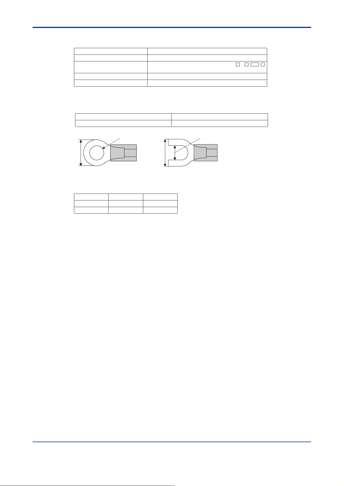
● Recommended Terminal Lugs
1-6
Applicable wire size Tightening torque
0.3 to 1.65 mm
7 mm or less
2
3.7mm
or
7 mm or less
● Terminal Covers (Optional parts)
Target Model Part Number Sales Unit
UM351 T9115YD 1
UM331 T9115YE 1
0.8 N·m or less
3.7mm
IM 05F01D12-41E 4th Edition: May 31, 2006-00
Page 15

<Toc> <1. Installation>
1.4 Hardware Specifications
PV Input Signals
• Number of inputs: 1 (terminals 11-12-13)
• Input type: Universal input system. The input type can be selected with the software.
• Sampling period: 250 ms
• Burnout detection: Functions at TC, RTD, standard signal (0.4 to 2 V or 1 to 5 V)
Upscale, downscale, and off can be specified.
For standard signal, burnout is determined to have occurred if it is 0.1 V or less.
• Input bias current: 0.05 A (for TC or RTD b-terminal)
• Measurement current (RTD): About 0.13 mA
• Input resistance: 1 M or more for thermocouple or mV input
About 1 M for DC voltage input
• Allowable signal source resistance: 250 or less for thermocouple or mV input
Effects of signal source resistance: 0.1 V/ or less
2 k or less for DC voltage input
Effects of signal source resistance: About 0.01%/100 V
1-7
• Allowable wiring resistance: for RTD input
Maximum 150 /wire: Conductor resistance between three wires should be equal
However, 10 /wire for a maximum range of -150.0 to 150.0C.
Wire resistance effect: 0.1C/10
• Allowable input voltage: 10 V DC for thermocouple, mV, or RTD input
20 V DC for DC voltage input
• Noise rejection ratio: 40 dB (50/60 Hz) or more in normal mode
120 dB (50/60 Hz) or more in common mode
• Reference junction compensation error: 1.0C (15 to 35C)
1.5C (0 to 15C, 35 to 50C)
• Applicable standards: JIS, IEC, DIN (ITS-90) for thermocouples and RTD
Loop Power Supply
Power is supplied to a two-wire transmitter.
(15 V DC: terminals
A resistor (10 to 250 ) connected between the indicator and transmitter converts a
current signal into a voltage signal, which is then read via the PV input terminal.
Supply voltage: 14.5 to 18.0 V DC, max. 21 mA (provided with a protection circuit
against a field short-circuit); 21.6 to 28.0 V DC, max. 30 mA (only for models with 24 V
DC loop power supply)
16-17
; 24 V DC: terminals 21-22)
IM 05F01D12-41E 4th Edition: May 31, 2006-00
Page 16

<Toc> <1. Installation>
Retransmission Output
Outputs the PV value.
Either the retransmission output or the loop power supply can be used with terminals
16-17
.
1-8
• Number of outputs: 1 (terminals
16-17
)
• Output signal: 4-20 mA DC
• Load resistance: 600 or less
• Output accuracy: 0.3% of span under standard operating conditions (232C,
5510% RH, power frequency of 50/60 Hz)
Contact Inputs
• Purpose: Resetting of PV peak and bottom values
• Number of inputs: 1
• Input type: Non-voltage contact or transistor open collector input
• Input contact rating: 12 V DC, 10 mA or more
• On/off determination: For non-voltage contact input, contact resistance of 1 k or less
is determined as “on” and contact resistance of 20 k or more as “off.”
For transistor open collector input, input voltage of 2 V or less is determined as “on”
and leakage current must not exceed 100 A when “off.”
• Minimum status detection hold time: About 1 second
Contact Outputs
• Purpose: Alarm output, FAIL output, and others
• Number of outputs: 4 (Max).
• Relay contact rating for Alarm 1 to 3: 240 V AC, 1 A, or 30 V DC, 1 A; 1a
• Relay contact rating for Alarm 4: 250 V AC, 3 A, or 30 V DC, 3 A (resistance load)
3 terminals (NC, NO, Common); 1c, (FAIL output : 1b)
Display Specifications
• PV display: 4-digit, 7-segment red LED display, character height of 20 mm (for both
UM351 and UM331)
• Setpoint display: 4-digit, 7-segment, red LEDs, character height of 9.3 mm (for both
UM351 and UM331)
• Status indicating lamps: LEDs
Safety and EMC Standards
• Safety: Complies with IEC/EN61010-1 (CE), approved by C22.2 No.61010-1, approved by UL508.
Installation category : CAT. II Pollution degree : 2 (IEC/EN61010-1, C22.2 No.61010-
1)
Measurement category : I (CAT. I : IEC/EN61010-1)
Rated measurement input voltage : 10V DC max.(across terminals), 300V AC
max.(across ground)
IM 05F01D12-41E 4th Edition: May 31, 2006-00
Page 17
<Toc> <1. Installation>
Rated transient overvoltage : 1500V (Note)
Note : It is a value on the safety standard which is assumed by IEC/EN61010-1 in
Measurement category I, and is not the value which guarantees an apparatus performance.
This equipment has Measurement category I, therefore do not use the equipment for
measurements within Measurement categories II, III and IV.
CAUTION
1-9
Measurement category
1
2
3
4
CAT.1
CAT.2
CAT.3
CAT.4
Entrance
Cable
Construction, Installation, and Wiring
Description
For measurements performed on circuits not directly connected to MAINS.
For measurements performed on circuits directly connected to the low voltage installation.
For measurements performed in the building installation.
For measurements performed at the source of the low-voltage installation.
Internal Wiring
3
4
Outlet
2
T
1
Appliances, portable equipments, etc.
Distribution board, circuit breaker, etc.
Overhead wire, cable systems, etc.
Remarks
• EMC standards: Complies with EN61326, EN61000-3-2, EN61000-3-3 and EN55011
(CE).
AS/NZS 2064 compliant (C-Tick).
Class A Group 1.
The instrument continues to operate at a measuring accuracy of within 20% of the
range during tests.
• Construction: Dust-proof and drip-proof pront panel conforming to IP55. For side-byside close installation the indicator loses its dust-proof and drip-proof protection.
• Material: ABS resin and polycarbonate
• Case color: Black
• Weight: About 1 kg or less
• Dimensions:
UM351 96 (W) 96 (H) 100 (depth from panel face) mm
UM331 96 (W) 48 (H) 100 (depth from panel face) mm
• Installation: Panel-mounting type. With top and bottom (or right and left) mounting
hardware (1 each)
• Panel cutout dimensions:
UM351 92
UM331 92
+0.8
(W) 92
0
+0.8
(W) 45
0
+0.8
(H) mm
0
+0.6
(H) mm
0
• Installation position: Up to 30 upward facing (not designed for facing downward)
• Wiring: M3.5 screw terminals (for signal wiring and power/ground wiring as well)
IM 05F01D12-41E 4th Edition: May 31, 2006-00
Page 18

<Toc> <1. Installation>
Power Supply Specifications
• Power supply: Rated voltage of 100 to 240 V AC (10%), 50/60 Hz
• Power consumption: Max. 20 VA (8.0 W max.)
• Internal fuse rating: 250 VAC, 1.6A time-lug fuse
• Data backup: Non-volatile memory (can be written to up to 100,000 times)
• Withstanding voltage
- Between primary terminals* and secondary terminals**:
At least 1500 V AC for 1 minute
- Between primary terminals* and grounding terminal:
At least 1500 V AC for 1 minute
- Between grounding terminal and secondary terminals**:
At least 1500 V AC for 1 minute
- Between secondary terminals**:
At least 500 V AC for 1 minute
* Primary terminals indicate power terminals and relay output terminals
** Secondary terminals indicate analog I/O signal, and contact input terminals
1-10
• Insulation resistance: 20 M or more at 500 V DC between power terminals and
grounding terminal
• Grounding: Class D grounding (grounding resistance of 100 or less)
Signal Isolations
• PV input terminals: Isolated from other input/output terminals. Not isolated from
internal circuit.
• 15 V DC loop power supply terminals: Not isolated from 4-20 mA analog output.
Isolated from other input/output terminals and internal circuit.
• 24 V DC loop power supply terminals: Isolated from 4-20 mA analog output terminals,
other input/output terminals and internal circuit.
• 4-20 mA analog output terminals (for retransmission): Not isolated from 15 V DC loop
power supply. Isolated from other input/output terminals and internal circuit.
• Contact input terminals: Not isolated from communication terminals. Isolated from
other input/output terminals and internal circuit.
• Relay contact output terminals: Not isolated between relay contact output terminals.
Isolated from other input/output terminals and internal circuit.
• RS-485 communication terminals: Not isolated from contact input terminals. Isolated
from other input/output terminals and internal circuit.
• Power terminals: Isolated from other input/output terminals and internal circuit.
• Grounding terminals: Isolated from other input/output terminals and internal circuit.
IM 05F01D12-41E 4th Edition: May 31, 2006-00
Page 19

<Toc> <1. Installation>
Environmental Conditions
• Normal operating conditions:
Ambient temperature: 0 to 50C (40C or less for side-by-side close installation)
0 to 40C if the 24 V DC loop power supply of Model UM331 is used
Temperature change rate: 10C/h or less
Ambient humidity: 20 to 90% RH (no condensation allowed)
Magnetic field: 400 A/m or less
Continuous vibration at 5 to 14 Hz: Full amplitude of 1.2 mm or less
Continuous vibration at 14 to 150 Hz: 4.9 m/s
Short-period vibration: 14.7 m/s
Shock: 147 m/s
2
or less, 11 ms
2
, 15 seconds or less
Installation height: Height above sea level of 2000 m or less
Warm-up time: 30 minutes or more after power on
• Transportation and storage conditions:
Temperature: -25 to 70C
Temperature change rate: 20C/h or less
Humidity: 5 to 95% RH (no condensation allowed)
• Effects of changes in operating conditions
- Effects from changes in ambient temperature:
- On voltage or thermocouple input, 1 V/C or 0.01% of F.S./C,
whichever is larger
2
or less
1-11
- On RTD input, 0.05C/C (ambient temperature) or less
- On analog output, 0.05% of F.S./C or less
- Effects from power supply fluctuation (within rated voltage range)
- On analog input, 1 V/10 V or 0.01% of F.S./10 V, whichever is
larger
- On analog output, 0.05% of F.S./10 V or less
IM 05F01D12-41E 4th Edition: May 31, 2006-00
Page 20

<Toc> <1. Installation>
1.5 Terminal Wiring Diagrams
NOTE
Do not use unassigned terminals as relay terminals.
Terminal wiring diagrams are shown on and after the next page.
1-12
IM 05F01D12-41E 4th Edition: May 31, 2006-00
Page 21

■ UM351 Standard Type (Model UM351-0䊐 or UM351-3䊐)
Power supply
Relay contact output
Contact rating: 250 V AC, 3 A
30 V DC, 3 A (resistance load)
* Wiring can only be carried out
for indicators with communication
functions.
Maximum baud rate: 9600 bps
Allowable range: 100 to 240 V AC (
10%)
(free voltage)
50/60 Hz shared
PV input
* Not configured at factory before shipment
See “2.
Initial Settings,” for more
information.
* Wiring can only be carried out
for indicators with 24 V DC
loop power supply.
16
17
Retransmission output
4-20 mA DC
16
17
15 V DC loop power supply
14.5-18.0 V DC
(21 mA DC max.)
* PV retransmission is configured at factory
before shipment.
Load resistance: 600
Ω or less
* If 15 V DC loop power supply is used,
retransmission output cannot be used.
-
+
-
+
1
2
3
4
5
6
7
8
9
10
21
22
23
24
25
26
27
28
29
30
11
12
13
14
15
16
17
18
19
20
8
9
10
L
N
12
13
11
12
13
12
13
21
22
21.6-28.0 V DC
(30 mA DC max.)
23
24
25
26
27
SDB(+)
SDA(-)
RDB(+)
RDA(-)
SG
6
5
4
7
AL1
AL2
AL3
COM
Relay contact rating: 240 V AC, 1 A
30 V DC, 1 A (resistance load)
1
2
3
Alarm 4 output
NC
NO
COM
A
b
B
UM
+
-
* Wiring can only be carried out for
UM351-䊐1 or UM351-
䊐2.
-
+
-
+
TC input
RTD input
mV/V input
12
13
+
-
Note: Connecting a 250
Ω resistor to the terminals is
optional.
Model: X010-250-2 (resistor with M3.5 crimp-on
terminal lugs)
* When receiving 4-20 mA DC current signals,
set the PV input type to 1-5 V DC (setpoint
“41”).
䊏 Receiving 4-20 mA DC Current
Signals with the Indicator
250 Ω
19
20
DI1
COM
Resets the PV
peak and bottom values
when DI1 is changed
from OFF to ON
.
Common
UM
Contact input
Contact
Contact rating: 12 V DC, 10 mA or more
DI1
COM
+5V
Transistor contact
19
20
RS-485 communication
Alarm output
Relay
Alarm 1 output
Alarm 2 output
Alarm 3 output
Common
Power supply
24 V DC loop
power supply
4-20mA
CAUTION
Before carrying out wiring, turn off the power
to the indicator and check that cables to be
connected are not alive with a tester or the like
because there is a possibility of electric shock.
<Toc> <1. Installation>
IM 05F01D12-41E 4th Edition: May 31, 2006-00
1-13
Page 22

■ UM331 Standard Type (Model UM331-0䊐 or UM331-3䊐)
24 V DC Power Supply Wiring to Two-wire Sensor
15 V DC Power Supply Wiring to Two-wire Sensor
12
13
+
-
Note: Connecting a 250
Ω resistor to the terminals is
optional.
Model: X010-250-2 (resistor with M3.5 crimp-on
terminal lugs)
* When receiving 4-20 mA DC current signals,
set the PV input type to 1-5 V DC (setpoint
“41”).
䊏 Receiving 4-20 mA DC Current
Signals with the Indicator
250 Ω
4-20 mA
12
13
11
12
13
12
13
A
b
B
-
+
-
+
TC input
RTD input
mV/V input
6
5
4
7
AL1
AL2
AL3
COM
UM
16
17
Retransmission output
4-20 mA DC
16
17
15 V DC loop power supply
14.5-18.0 V DC
(21 mA DC max.)
* PV retransmission is configured at factory
before shipment.
Load resistance: 600
Ω or less
* If 15 V DC loop power supply is used,
retransmission output cannot be used.
-
+
-
+
11
21
13
23
3
15
25
5
19
29
9
1
17
27
7
12
22
14
24
4
16
26
6
20
30
10
2
18
28
8
8
9
Power supply
10
L
N
Power supply
23
24
RS-485 communication
* Wiring can only be carried out
for indicators with communication
functions.
Maximum baud rate: 9600 bps
25
26
27
SDB(+)
SDA(-)
RDB(+)
RDA(-)
SG
19
20
DI1
COM
Resets the PV
peak and bottom values
when DI1 is changed
from OFF to ON
.
Common
1
2
Relay contact output
3
Alarm 4 output
NC
NO
COM
Contact rating: 250 V AC, 3 A
30 V DC, 3 A (resistance load)
* Wiring can only be carried out for
UM331-䊐1 or UM331-
䊐2.
CAUTION
Before carrying out wiring, turn off the power
to the indicator and check that cables to be
connected are not alive with a tester or the like
because there is a possibility of electric shock.
UM
* Wiring can only be carried out for indicators with 24 V DC
loop power supply.
12
13
16
17
Two-wire transmitter
PV input
0.4 to 2.0 V DC signal
Loop power
supply
14.5 to
18.0 V DC
External
resistor
(Note)
4-20 mA DC
Note: Connecting a 100
resistor to the terminals is optional.
Model: X010-100-2 (resistor with M3.5 crimp-on terminal lugs)
100
12
13
21
22
Two-wire transmitter
PV input
1 to 5 V DC signal
Loop power
supply
21.6 to
28.0 V
DC
External
resistor
(Note)
4-20 mA DC
Note: Connecting a 250
resistor to the terminals is optional.
Model: X010-250-2 (resistor with M3.5 crimp-on terminal lugs)
250
Contact input
Contact
Contact rating: 12 V DC, 10 mA or more
DI1
COM
+5V
Transistor contact
19
20
* Wiring can only be carried out
for indicators with 24 V DC
loop power supply.
21
22
21.6-28.0 V DC
(30 mA DC max.)
+
-
24 V DC loop
power supply
Alarm output
Relay
Alarm 1 output
Alarm 2 output
Alarm 3 output
Common
Relay contact rating: 240 V AC, 1 A
30 V DC, 1 A (resistance load)
Allowable range: 100 to 240 V AC (
10%)
(free voltage)
50/60 Hz shared
PV input
* Not configured at factory before shipment
See “2.
Initial Settings,” for more
information.
IM 05F01D12-41E 4th Edition: May 31, 2006-00
<Toc> <1. Installation>
1-14
Page 23

<Toc> <2. Initial Settings>
2. Initial Settings
This chapter describes examples of setting the types of PV input and alarm. Carrying out settings described herein allows you to perform basic monitoring. Refer to
examples of various settings to understand how to set parameters required. Refer to
“5.1 Parameter Map” for an easy to understand explanation of setting various
parameters. If you cannot remember how to carry out an operation during setting,
press the
ing display) that appears at power-on.
Setup Procedure
SET/ENT
key for more than 3 seconds. This brings you to the display (operat-
2-1
Power-on
Set PV input.
See “2.2 Setting PV Input Type (Setting First at Power-on),”
or “2.3 Changing PV Input Type.”
Set the alarm
type and other setup
parameters.
See “2.4 Changing the Alarm Type.”
Set the alarm
setpoints and other
operating parameters.
See “3.2 Setting Alarm Setpoints.”
Indicator operation
(Factory-set to “Unspecified.”)
Denotes a step that must always be followed.
Denotes a step that should be followed as necessary.
The following explanation of operation for the UM351’s panel, shown in the figure, is the
same as that of the UM331’s panel.
IM 05F01D12-41E 4th Edition: May 31, 2006-00
Page 24

<Toc> <2. Initial Settings>
2.1 Names and Functions of Front Panel Parts
2-2
4. SET/ENT key
Name of Part
Process variable (PV)
1.
display
Parameter setpoint display
2.
3. Alarm indicator lamps
SET/ENT
4.
key
and
5.
keys
SET/ENT
IMPORTANT
1. Process
variable (PV)
display
2. Parameter
Setpoint
display
3.
Alarm indicator
lamps
5. and keys
• Displays a PV value during operation.
• Displays a parameter symbol when you set a parameter.
• Displays an error code in red if the indicator fails.
Displays the setpoint of a parameter when it is configured.
If any of alarms 1 to 4 occurs, the respective alarm indicator lamp (AL1 to AL4) is lit (in orange).
Used to switch or register a parameter. Pressing the key for more than 3 seconds allows you to switch
between the operating display and the menu for operating parameter setting display alternately.
Used to change numerical values. On setting displays for various parameters, you can change parameters.
Pressing the key decreases a numerical value, while pressing the key causes it to increase. You can
hold down a key to gradually increase the speed of change.
2. Parameter
Setpoint display
Function
4. SET/ENT
key
1. Process
variable (PV)
display
3. Alarm indicator
lamps
5. and keys
The indicator automatically returns to the display at the time of power-on (i.e., Operating
display) if no key is operated for at least one minute.
IM 05F01D12-41E 4th Edition: May 31, 2006-00
Page 25

<Toc> <2. Initial Settings>
2.2 Setting PV Input Type (Setting First at Power-on)
NOTE
• The indicator displays the operating display when the power is turned on. However, if
PV input type has not been set, “IN” appears. In this case, first use the
display the input range code to use, then press the
the maximum value (RH) and minimum value (RL) of the PV input range (for voltage
input, set the maximum value (SH) and minimum value (SL) of the PV input scale).
• The indicator is configured to the initial value of each parameter at the factory before
shipment.
First check the initial values shown in “5.2 Lists of Parameters,” and change parameter values as necessary.
Example of Temperature Input Example of Voltage Input
1V 5V (Input signal)
-200°C 1370°C
0°C 800°C
Minimum value of
PV input range (RL)
Parameters to be set for temperature input
1. PV input type (IN): Set according to a sensor
2. Maximum value of PV input range (RH): Set the
maximum value of the range to be displayed.
3. Minimum value of PV input range (RL): Set the
minimum value of the range to be displayed.
Instrument
input range
PV input range
Maximum value of
PV input range (RH)
Set the actual
read-out
range.
Parameters to be set for voltage input
1. PV input type (IN): Set according to an input signal
2. Maximum value of PV input range (RH): Set the maximum value of an input signal.
3. Minimum value of PV input range (RL): Set the minimum value of an input signal.
4. Position of PV input decimal point (SDP): Set the position of the decimal point for PV input display.
5. Maximum value of PV input scale (SH): Set the maximum value of the scale to be displayed.
6. Minimum value of PV input scale (SL): Set the minimum value of the scale to be displayed.
2V 4V
PV input range
RL
PV input scale
0.0m3/h 50.0m3/h
Minimum value of
PV input scale (SL)
SET/ENT
Instrument
input range
Maximum value of
PV input scale (SH)
key to register it. Then, set
RH
Set the actual
read-out range.
2-3
key to
The following operating procedure describes an example of setting a K-type thermocouple
(-199.9C to 500.0C) and a measurement range of 0.0C to 200.0C.
Display screen at power-on
1.
The parameter “IN” for setting the PV
input type appears.
PV
AL1234
SET/ENT
Displays
parameter
“IN”.
Press the or key to display the
2.
required setpoint.
The figure below shows an example of
setting a K-type thermocouple (-199.9 to
500.0C). See the Instrument Input Range
Codes.
PV
AL1234
SET/ENT
Blinks during
change.
IM 05F01D12-41E 4th Edition: May 31, 2006-00
Page 26

<Toc> <2. Initial Settings>
2-4
3.
Press the
SET/ENT
key once to register the
setpoint.
PV
AL1234
SET/ENT
4.
Press the
SET/ENT
key once to display the
parameter “UNIT” (PV input unit).
PV
AL1234
SET/ENT
5.
Press the
SET/ENT
key once to display the
parameter “RH” (maximum value of PV
input range).
PV
AL1234
Displays
parameter
“UNIT”.
Displays
parameter
“RH”.
8.
Press the
SET/ENT
key once to display the
parameter “RL” (minimum value of PV
input range).
PV
AL1234
SET/ENT
Press the or key to display the
9.
required setpoint. The figure below shows
an example of setting the minimum value
of PV input range to 0.0C.
PV
AL1234
SET/ENT
10.
Press the
SET/ENT
key once to register the
setpoint.
PV
Displays
parameter
“RL”.
Blinks during
change.
SET/ENT
Press the or key to display the
6.
required setpoint. The figure below shows
an example of setting the maximum value
of PV input range to 200.0C.
PV
AL1234
SET/ENT
7.
Press the
SET/ENT
key once to register the
setpoint.
PV
AL1234
SET/ENT
Blinks during
change.
AL1234
SET/ENT
If the type of input is voltage, also configure the PV Input Decimal Point Position
(SDP), Maximum Value of PV Input Scale
(SH), and Minimum Value of PV Input Scale
(SL) parameters that are displayed after
this.
11.
Press the
SET/ENT
key for more than 3 seconds. This returns you to the display
shown at power-on (figure below).
PV
AL1234
SET/ENT
Displays PV.
The PV display in the figure above shows
the error code for input burnout ( ) if
PV input wiring is not yet complete. The
error code disappears when you wire the
PV input terminals correctly.
IM 05F01D12-41E 4th Edition: May 31, 2006-00
Page 27

<Toc> <2. Initial Settings>
■ Instrument Input Range Codes
Selected the unit from UNIT parameter.
Input Type
Unspecified
Thermocouple
RTD
Standard
signal
DC voltage
K
J4
T
B7
S8
R9
N10
E11
L(DIN) 12
U(DIN)
W15
Platinel 2 16
PR20-40 17
W97Re3W75Re25
JPt100
Pt100
0.4 to 2 V
1 to 5 V 41
0 to 2 V 50
0 to 10 V 51
-10 to 20 mV
0 to 100 mV
Instrument Input
Range Code
OFF
1
2
3
5
6
13
14
18
30
31
35
36
37
40
55 -10.00 to 20.00 mV
56 0.0 to 100.0 mV
* Performance in the standard condition (at 232C, 5510%RH, and 50/60 Hz power frequency.
Note 1: The accuracy is 0.3C of instrument range 1 digit for a temperature range from 0C to 100C.
Note 2: The accuracy is 0.5C of instrument range 1 digit for a temperature ranges from -100C to 0C and 100C to
200C.
* To receive a 4-20 mA DC signal, select a standard signal of 1 to 5 V DC and connect it to a 250 resistor. This
resistor is optional.
Model: X010-250-2 (resistor with M3.5 crimp-on terminal lugs)
Instrument
Input Range
Set the data item PV Input Type "IN" to the OFF option to leave the PV input
Set the data item PV Input Type "IN" to the OFF option to leave the PV input
type undefined.
type undefined.
-200 to 1370C
-300 to 2500F
-199.9 to 999.9C
0 to 2300F
-199.9 to 500.0C
-199.9 to 999.9F
-199.9 to 999.9C
-300 to 2300F
-199.9 to 400.0C
-300 to 750F
0.0 to 400.0C
-199.9 to 750.0F
0 to 1800C
32 to 3300F
0 to 1700C
32 to 3100F
0 to 1700C
32 to 3100F
-200 to 1300C
-300 to 2400F
-199.9 to 999.9C
-300 to 1800F
-199.9 to 900.0C
-300 to 1300F
-199.9 to 400.0C
-300 to 750F
0.0 to 400.0C
-199.9 to 750.0F
0 to 2300C
32 to 4200F
0 to 1390C
32 to 2500F
0 to 1900C
32 to 3400F
0 to 2000C
32 to 3600F
-199.9 to 500.0C
-199.9 to 999.9F
-150.0 to 150.0C
-199.9 to 300.0F
-199.9 to 850.0C
-300 to 1560F
-199.9 to 500.0C
-199.9 to 999.9F
-150.0 to 150.0C
-199.9 to 300.0F
0.400 to 2.000 V
1.000 to 5.000 V
0.000 to 2.000 V
0.00 to 10.00 V
0.1% of instrument range 1 digit for temperatures
equal to or higher than 0°C
0.2% of instrument range 1 digit for temperatures
below 0°C
0.15% of instrument range 1 digit for temperatures
equal to or higher than 400°C
5% of instrument range 1 digit for temperatures
below 400°C
0.15% of instrument range 1 digit
0.1% of instrument range 1 digit
0.25% of instrument range 1 digit for temperatures
below 0°C
0.1% of instrument range 1 digit for temperatures
equal to or higher than 0°C
0.2% of instrument range 1 digit for temperatures
below 0°C
0.2% of instrument range 1 digit
0.1% of instrument range 1 digit
0.5% of instrument range 1 digit for temperatures
equal to or higher than 800°C
No guarantee of accuracy for temperatures below 800°C
0.2% of instrument range 1 digit
0.1% of instrument range 1 digit (Note 1) (Note 2)
0.2% of instrument range 1 digit (Note 1)
0.1% of instrument range 1 digit (Note 1) (Note 2)
0.2% of instrument range 1 digit (Note 1)
0.1% of instrument range 1 digit
The read-out range can be scaled between -1999 and
9999.
Measurement Accuracy
2-5
IM 05F01D12-41E 4th Edition: May 31, 2006-00
Page 28

<Toc> <2. Initial Settings>
NOTE
The indicator may automatically initialize the registered operating parameter setpoints if
any change is made to the data item PV Input Type (IN), Maximum Value of PV Input
Range (RH), Minimum Value of PV Input Range (RL), PV Input Decimal Point Position
(SDP), Maximum Value of PV Input Scale (SH) or Minimum Value of PV Input Scale (SL).
After a change has been made to any of these data items, be sure to verify the registered
operating parameter setpoints to ensure that they are correct. If any data item has been
changed to its default, set it to a required value.
2-6
IM 05F01D12-41E 4th Edition: May 31, 2006-00
Page 29

<Toc> <2. Initial Settings>
2.3 Changing PV Input Type
The following operating procedure describes an example of changing the setting of K-type
thermocouple (-199.9 to 500.0C) to RTD Pt100 (-199.9 to 500.0C) and a measurement
range of 0.0 to 200.0C.
2-7
PV input terminal
Thermocouple/mV/V input
RTD input .................................................. - -
Bring the operating display into view
1.
(display appears at power on).
PV
AL1234
SET/ENT
2.
Press the
SET/ENT
key for more than 3 sec-
onds to call up the menu “OP.PA”.
PV
AL1234
SET/ENT
..............................
Displays PV.
Displays
menu “OP.PA”.
1312
-
131211
5.
Press the
SET/ENT
key once to display the
menu “FUNC”.
Displays
PV
AL1234
SET/ENT
Press the key once to display the
6.
menu “FUNC”.
menu “I/O”.
Displays
PV
AL1234
SET/ENT
menu “I/O”.
Press the key once to display the
3.
menu “STUP”.
PV
AL1234
SET/ENT
4.
Press the
SET/ENT
key once to display the
parameter “PWD”.
PV
AL1234
SET/ENT
Displays
menu “STUP”.
Displays
parameter
“PWD”.
7.
Press the
SET/ENT
key once to display the
parameter “IN” (PV input type).
PV
AL1234
SET/ENT
Press the or key to display the
8.
required setpoint. The figure below shows
an example of changing to RTD Pt100
(-199.9 to 500.0C).
PV
AL1234
SET/ENT
Blinks during
Displays
parameter
“IN”.
change.
IM 05F01D12-41E 4th Edition: May 31, 2006-00
Page 30

<Toc> <2. Initial Settings>
2-8
9.
Press the
SET/ENT
key once to register the
setpoint.
PV
AL1234
SET/ENT
10.
Press the
SET/ENT
key once to display the
parameter “UNIT” (PV input unit).
PV
AL1234
SET/ENT
11.
Press the
SET/ENT
key once to display the
parameter “RH” (maximum value of PV
input range).
PV
AL1234
Displays
parameter
“UNIT”.
Displays
parameter
“RH”.
14.
Press the
SET/ENT
key once to display the
parameter “RL” (minimum value of PV
input range).
PV
AL1234
SET/ENT
Press the or key to display the
15.
required setpoint. The figure below shows
an example of setting the minimum value
of PV input range to 0.0C.
PV
AL1234
SET/ENT
16.
Press the
SET/ENT
key once to register the
setpoint.
PV
Displays
parameter
“RL”.
Blinks during
change.
SET/ENT
Press the or key to display the
12.
required setpoint. The figure below shows
an example of setting the maximum value
of PV input range to 200.0C.
PV
AL1234
SET/ENT
13.
Press the
SET/ENT
key once to register the
setpoint.
PV
AL1234
SET/ENT
Blinks during
change.
AL1234
SET/ENT
17.
Press the
SET/ENT
key for more than 3 seconds.
This returns you to the display shown at
power-on (figure below).
PV
AL1234
SET/ENT
Displays PV.
* If the type of input is voltage, also config-
ure the PV Input Decimal Point Position
(SDP), Maximum Value of PV Input Scale
(SH), and Minimum Value of PV Input
Scale (SL) parameters that are displayed
after this.
IM 05F01D12-41E 4th Edition: May 31, 2006-00
Page 31

<Toc> <2. Initial Settings>
2.4 Changing Alarm Type
The following operating procedure describes an example of changing alarm-1 (factory-set
default: PV high limit alarm) to PV low limit alarm.
When you have changed alarm type, the alarm setpoint will be initialized; set the alarm
setpoint again.
2-9
Alarm output terminals Factory-set defaults
Alarm-1 (terminal numbers )............PV high limit alarm
Alarm-2 (terminal numbers )............PV low limit alarm
Alarm-3 (terminal numbers )............PV high limit alarm
Alarm-4 (terminal numbers )......PV low limit alarm
Bring the operating display into view
1.
(appears at power-on).
PV
AL1234
SET/ENT
2.
Press the
SET/ENT
key for more than 3 sec-
onds to call up the menu “OP.PA”.
PV
AL1234
6 7
-
5 7
-
4 7
-
2 31
--
-
Displays PV.
Displays
menu “OP.PA”.
5.
Press the
SET/ENT
key once to display the
menu “FUNC”.
PV
SET/ENT
6.
Press the
SET/ENT
key once to display the
parameter “AL1” (alarm-1 type).
PV
Displays
menu “FUNC”.
AL1234
Displays
parameter
“AL1”.
AL1234
SET/ENT
Press the key once to display the
3.
menu “STUP”.
PV
AL1234
SET/ENT
4.
Press the
SET/ENT
key once to display the
parameter “PWD”.
PV
AL1234
SET/ENT
Displays
menu “STUP”.
Displays
parameter
“PWD”.
SET/ENT
Press the or key to display the
7.
required setpoint. The figure below shows
an example of setting PV low limit alarm.
PV
AL1234
SET/ENT
Blinks during
change.
IM 05F01D12-41E 4th Edition: May 31, 2006-00
Page 32

<Toc> <2. Initial Settings>
2-10
8.
Press the
SET/ENT
key once to register the
setpoint.
PV
AL1234
SET/ENT
You can take the same steps for alarm-2
type (AL2), alarm-3 type (AL3), and alarm-4
type (AL4) that are displayed after this.
■ List of Alarm Types
The table below shows the alarm types and alarm actions.
In the table, codes 1, 2, 9, and 10 are not provided with stand-by actions, while codes 11,
12, 19, and 20 are provided with stand-by actions.
Alarm action
Alarm type
“Open/close” shows status of relay contact,
and “lit” and “unlit” shows status of lamp
No alarm OFF
Hysteresis
PV high limit
PV low limit
Open (unlit)
Closed (lit)
Alarm setpoint
PV
Hysteresis
Alarm setpoint PV
Closed (lit)
Open (unlit)
Contact
closes
if alarm
occurs
1
11
2
12
Contact
opens
if alarm
occurs
Press the
9.
onds. This returns you to the display
shown at power-on (figure below).
See “3.2 Setting Alarm Setpoints” when
setting an alarm setpoint.
Alarm type
De-energized
on PV high limit
De-energized
on PV low limit
SET/ENT
key for more than 3 sec-
PV
AL1234
SET/ENT
Alarm action
“Open/close” shows status of relay contact,
and “lit” and “unlit” shows status of lamp
Hysteresis
Closed
(unlit)
Open (lit)
Alarm setpoint
PV
Hysteresis
Open (lit)
Alarm setpoint
Closed
PV
(unlit)
Displays PV.
Alarm type codeAlarm type code
Contact
closes
if alarm
occurs
Contact
opens
if alarm
occurs
9
19
10
20
Fault diagnosis output (Note 1) FAIL output (Note 2)
Note 1: Fault diagnosis output
Turns on in case of input burnout, A/D converter failure, or reference junction compensation (RJC) failure.
Note 2: FAIL output
Turns off in case of program failure, ROM failure, RAM failure, or power failure. This output is on during normal
operation.
If it turns off, the retransmission output is set to 0%, the alarm output is set to OFF, and the indicator stops.
Stand-by Action
C
Treated
Normal
as normal
It is effective in the following
cases where;
- the power is turned on
- the alarm type is changed
The alarm output does not
turn on in this region even
if the PV value is below the
low limit of the alarm setpoint.
Power-on
Abnormal
The alarm
output turns on.
Low limit of
alarm setpoint
Time
IM 05F01D12-41E 4th Edition: May 31, 2006-00
2221
Page 33

<Toc> <2. Initial Settings>
2.5 Setting Hysteresis in Alarm Setpoint
The following operating procedure describes an example of setting a 5.0°C hysteresis level
in the alarm setpoint.
2-11
Bring the operating display into view
1.
(appears at power-on).
PV
AL1234
SET/ENT
2.
Press the
SET/ENT
key for more than 3 sec-
onds to call up the menu “OP.PA”.
PV
AL1234
SET/ENT
Press the key once to display the
3.
menu “STUP”.
Displays PV.
Displays
menu “OP.PA”.
6.
Press the
SET/ENT
key several times to
display the parameter “HY1” (alarm-1
hysteresis).
PV
AL1234
SET/ENT
Press the or key to display the
7.
required setpoint.
PV
AL1234
SET/ENT
8.
Press the
SET/ENT
key once to register the
setpoint.
Displays
parameter
“HY1”.
Blinks during
change.
Press the
4.
parameter “PWD”.
Press the
5.
menu “FUNC”.
PV
AL1234
SET/ENT
SET/ENT
key once to display the
PV
AL1234
SET/ENT
SET/ENT
key once to display the
PV
AL1234
Displays
menu “STUP”.
Displays
parameter
“PWD”.
Displays
menu “FUNC”.
PV
AL1234
SET/ENT
You can take the same steps for alarm-2
hysteresis (HY2), alarm-3 hysteresis (HY3),
and alarm-4 hysteresis (HY4) that are
displayed after this.
9.
Press the
SET/ENT
key for more than 3 seconds. This returns you to the display
shown at power-on (figure below).
PV
Displays PV.
AL1234
SET/ENT
SET/ENT
IM 05F01D12-41E 4th Edition: May 31, 2006-00
Page 34

<Toc> <2. Initial Settings>
2-12
2.6 Setting the PV display color changing function “Active Color PV Display”
The following operating procedure describes an example of changing PV color mode
(factory-set default: Fixed in red mode) to Link to alarm 1 mode.
Bring the operating display into view (appears at
(1)
power on).
PV
AL1234
SET/ENT
Press the key for more than 3 seconds to
(2)
call up the menu “OP.PA.”
SET/ENT
Displays PV.
Displays
PV
AL1234
SET/ENT
Press the key once to display the menu
(3)
“STUP.”
PV
AL1234
SET/ENT
Press the key once to display the parameter
(4)
“PWD.”
Press the key once to display the menu
(5)
“FUNC.”
SET/ENT
PV
AL1234
SET/ENT
SET/ENT
PV
menu “OP.PA”
Displays
menu “STUP”
Displays
menu “PWD”
Displays
menu “FUNC”
Press the key several times to display the
(6)
menu “PCMD” (PV color mode).
Press the key or key to display the
(7)
required setpoint. The figure below shows an
SET/ENT
SET/ENT
PV
AL1234
parameter “PCMD”
example of setting Link to alarm 1 mode.
PV
during change
AL1234
SET/ENT
Press the key once to register the setpoint.
(8)
SET/ENT
If PCMD = 6, 7, 8 or 9,
PV
also set the relating
paraemters PCCH
AL1234
SET/ENT
Press the key for more than 3 seconds.
(9)
This returns you to the display shown at power-on
SET/ENT
(High limit for PV color
change) and PCCL
(Low limit for PC color
change).
(figure blow).
PV
AL1234
SET/ENT
Displays PV.
Displays
Blinks
SET/ENT
AL1234
IM 05F01D12-41E 4th Edition: May 31, 2006-00
Page 35

<Toc> <2. Initial Settings>
2-13
2.7 Setting the High Limit and Low limit for PV Color change
The following operating procedure describes an example of changing PV display color by
linking to PV. Set High limit and Low limit for PV color change. Setting for both of High limit
and Low limit is required.
Bring the operating display into view (appears at
(1)
power-on).
PV
AL1234
SET/ENT
Press the key for more than 3 seconds to
(2)
call up the menu “OP.PA.”
Press the key several times to display the
(3)
parameter “PCCH.”
SET/ENT
PV
AL1234
SET/ENT
SET/ENT
PV
AL1234
SET/ENT
Displays PV.
menu “OP.PA”
Displays parameter
“PCCH.”
Displays
Press the key or key to display the
(4)
required setpoint.
PV
AL1234
SET/ENT
Press the key once to register the
(5)
setpoint.
SET/ENT
PV
AL1234
SET/ENT
Blinks during
PCCL (Low limit for PV color change
parameter) that is displayed after this can be
Press the key for more than 3 seconds.
(6)
This returns you to the display shown at power-
SET/ENT
on (figure below).
PV
AL1234
SET/ENT
change.
Displays PV.
IM 05F01D12-41E 4th Edition: May 31, 2006-00
Page 36

Blank Page
Page 37

<Toc> <3. Operations>
3. Operations
3-1
This chapter describes key entries for operating the indicator. If you cannot remember how to carry out an operation during setting, press the
seconds. This brings you to the display (operating display) that appears at poweron.
SET/ENT
key for more than 3
NOTE
Do not use the instrument generating strong magnetic field such as radio equipment and
the like near the indicator. This may cause the fluctuation of the PV value.
3.1 Monitoring-purpose Operating Display Available during Operation
The following is the monitoring-purpose operating display available during operation.
Power On
SET/ENT
PV
AL1234
Displays PV.
IM 05F01D12-41E 4th Edition: May 31, 2006-00
Page 38

<Toc> <3. Operations>
3.2 Setting Alarm Setpoints
The following operating procedure describes an example of setting a value of 160.0 in the
alarm-1 setpoint parameter. Before setting the alarm setpoint, check the alarm type.
To change the alarm type, see “2.4 Changing Alarm Type.”
3-2
Alarm output terminals
Alarm-1 (terminal numbers )............PV high limit alarm
Alarm-2 (terminal numbers )............PV low limit alarm
Alarm-3 (terminal numbers )............PV high limit alarm
Alarm-4 (terminal numbers ).......PV low limit alarm
Bring the operating display into view
1.
(display appears at power on).
PV
AL1234
SET/ENT
2.
Press the
SET/ENT
key for more than 3 sec-
onds to call up the menu “OP.PA”.
PV
AL1234
SET/ENT
6 7
5 7
4 7
1
Factory-set defaults
-
-
-
2
3
--
Displays PV.
Displays
menu “OP.PA”.
5.
Press the
SET/ENT
key once to register the
setpoint.
PV
AL1234
SET/ENT
You can take the same steps for alarm-2
setpoint (A2), alarm-3 setpoint (A3), and
alarm-4 setpoint (A4) that are displayed
after this.
6.
Press the
SET/ENT
key for more than 3 seconds. This returns you to the display
shown at power-on (figure below).
PV
Displays PV.
3.
Press the
SET/ENT
key once to display the
parameter “A1”.
PV
AL1234
SET/ENT
Press the or key to display the
4.
required setpoint.
PV
AL1234
SET/ENT
AL1234
SET/ENT
Displays
parameter
“A1”.
Blinks during
change.
IM 05F01D12-41E 4th Edition: May 31, 2006-00
Page 39

<Toc> <4. Troubleshooting and Maintenance>
4. Troubleshooting and Maintenance
4.1 Troubleshooting
■ Troubleshooting Flow
If the operating display does not appear after turning on the indicator’s power, try to solve
the problem by following the procedure below.
If the problem seems to be complex, contact the vendor from which you purchased the
instrument.
Is the instrument
defective?
Yes
Totally
inoperable?
Yes
No
Is key
operation
faulty?
Yes
No
Is display
faulty?
Yes
No
Is I/O
signal faulty?
Yes
No
Is
communication
link faulty?
Yes
4-1
Check wiring on the
power supply
terminals.
Check the supply
voltage.
Normal?
Ask the vendor for repair.
No
No
Yes
Check the key lock
setting.
No
Correct
errors.
Correct?
Yes
Find the cause.
Is
key lock
enabled?
Disable
key lock.
Yes
Turn off power, and
then turn it on
again.
Check the
instrument’s I/O
specifications.
Check the specifications
of I/O counterpart for
wrong polarity.
No communication
capability.
IMPORTANT
Take note of the parameter settings when asking the vendor for repair.
Check the
instrument's suffix
code.
No
Does the code
include a communication
option?
Check the
communication-related
parameters.
Check
communication wiring.
Check the specifications
of communication
counterpart.
IM 05F01D12-41E 4th Edition: May 31, 2006-00
Page 40

<Toc> <4. Troubleshooting and Maintenance>
■ Errors at Power on
The following table shows errors that may be detected by the fault diagnosis function when
the power is turned on.
4-2
Error indication
(on PV display unit)
(E000)
(E001)
(E002)
PV decimal point blinks.
(E400)
Description
of error
Faulty RAM
Faulty ROM
System data error
Faulty calibration
value
Parameter error
PV
None
0%
Normal action
(out of
accuracy)
0%
■ Possible Errors during Operation
The following shows possible errors occurring during operations.
Error indication
(on PV display unit)
Displays “RJC”
and PV
alternately
PV value blinks.
(E300)
(B.OUT)
(OVER) or
(-OVER)
SP decimal point
blinks. (on
setpoint display
unit)
All indications off Faulty if power off/on does
All indications off Check for abnormal power.
Description
of error
RJC error
EEPROM
error
A/DC error
PV burnout
error
Excessive PV
Out of -5 to
105%
Faulty
communication line
Runaway (due
to defective
power or
noise)
Power off
PV
Measured
with RJC=OFF
Normal action
105
%
Dependent on the BSL
parameter
Up-scale: 105%
Down-scale: -5%
-5% or 105%
Normal action
None
None
Control
output
0% or less
or OFF
Normal action
(out of
accuracy)
Preset value
Control
output
Normal
action
Normal
action
Preset
value
Preset
value
Normal
action
Normal
action
0% or less
or OFF
0
Normal
action
Normal
action
Normal
action
Normal
action
Normal
action
Normal
action
OFF
OFF
%
Alarm
output
OFF
Normal action
(out of
accuracy)
OFF 0%
Retransmis-
Alarm
sion output
output
Normal
action
Normal
action
Normal
action
Normal
action
Normal
action
Normal
action
0% or
less
0
%
Retransmission
output
0% or less Stopped
0%
Normal action
(out of
accuracy)
Commu-
Normal
action
Normal
action
Normal
action
Normal
action
Normal
action
Normal
action
Stopped
Stopped
Communi-
cation
Normal
action
nication
Faulty
Contact us for repair.
Faulty
Contact us for repair.
Check wires and
sensor.
Check process.
Check wires and
communication parameters,
and make resetting.
Recovery at normal receipt
not reset start the unit.
Contact us for repair.
Remedy
Faulty
Contact us
for repair.
Check and set
the parameters,
as they have
been set to the
limited values.
Remedy
IM 05F01D12-41E 4th Edition: May 31, 2006-00
Page 41

<Toc> <4. Troubleshooting and Maintenance>
■ If a Power Failure Occurs during Operation
● Momentary Power Failures shorter than 20 ms
The indicator is not affected at all and continues normal operation.
● Momentary Power Failures of 20 ms or longer
• The alarm function of the indicator continues to work normally. (Alarms with the standby feature temporarily return to their stand-by state, however.)
• Setting parameters that have already been configured retain their settings.
4-3
IM 05F01D12-41E 4th Edition: May 31, 2006-00
Page 42

<Toc> <4. Troubleshooting and Maintenance>
4.2 Maintenance
This section describes the cleaning and maintenance of the UM351/UM331.
4.2.1 Cleaning
The front panel and operation keys should be gently wiped with a dry cloth.
NOTE
Do not use alcohol, benzine, or any other solvents.
4.2.2 Replacing Brackets
When the brackets are broken or lost, purchase the following brackets for replacement.
4-4
Target Model Part No.
UM351 T9115NL
UM331 T9115NK
SEE ALSO
“1.2 How to Install,” for how to replace brackets.
4.2.3 Attaching Terminal Cover
When a terminal cover is necessary, purchase the following part.
Target Model Part No.
UM351 T9115YD
UM331 T9115YE
Sales Unit
A large bracket and small bracket in pair
Small brackets in pair
Sales Unit
1
1
IM 05F01D12-41E 4th Edition: May 31, 2006-00
Page 43

<Toc> <4. Troubleshooting and Maintenance>
■ Attaching Terminal Cover
The procedure for attaching the terminal cover is as follows.
Do not touch the terminals on the rear panel when power is being supplied to the indicator.
Doing so may result in electric shock.
4-5
CAUTION
1.
Before attaching the terminal cover, turn off the source circuit breaker and use a tester to
check that the power cable is not conducting any electricity.
Before attaching the terminal cover, fold it once or twice so that the side which has the
“Handle With Care” symbol ( ), is on the outside.
Fold over.
Grooved
Fold over.
Grooved
Folding Direction of Terminal Cover
Alert symbol
on the back
NOTE
Do not fold the terminal cover the wrong way, doing so not only reduces the cover’s
strength but may also cause the hinge to crack, thereby disabling attachment.
With the cover properly folded, fit its top and bottom holes to the protrusions of the
2.
mounting brackets.
Fit the hole of the
terminal cover to the
protrusion on the
mounting bracket.
Attaching Terminal Cover
IM 05F01D12-41E 4th Edition: May 31, 2006-00
Page 44

<Toc> <4. Troubleshooting and Maintenance>
4.2.4 Replacing Parts with a Limited Service Life
The following UM351/UM331 parts have a limited service life.
The service life given in the table assume that the indicator is used under normal operating
conditions.
4-6
Part
Aluminum electrolytic condenser
EEPROM About 100,000 times of writings
Alarm 4 output relays About 100,000 more ON-OFF operations or with resistance load
About 10 years (rated)
Service life
IM 05F01D12-41E 4th Edition: May 31, 2006-00
Page 45

<Toc> <5. Parameters>
5. Parameters
This chapter contains a parameter map as a guideline for setting parameters, and
lists of parameters for recording User Settings.
5.1 Parameter Map
5-1
UM351/UM331 Parameter Map
Operating Display
PV display
SET3S
A1
A2
A3
A4
PEAK
BOTM
FL
BS
PCCH
PCCL
SET
SET3S
SET3S
To switch the parameter
display, press the key.
Displayed only for
UM351-䊐1, UM351-䊐2,
UM331-䊐1, UM331-䊐2
Displayed when PCMD (PV color mode
parameter) = 6 or 7
Menu
SET/ENT
SET
SET
SET
SET3S
Press the key once.
Press the key for 3 seconds.
Press the or key once.
STUPOP.PA
SET
Password
check display
Password input
(No password is required
when PWD = 0.)
SET
Setup Parameter
Alarm/
Communication
related Input related
Setting Display
FUNC
SET SET
PCMD
AL1
AL2
AL3
AL4
HY1
Displayed only for
UM351-䊐1, UM351-䊐2,
UM331-䊐1, UM331-䊐2
HY2
HY3
HY4
DY1
Displayed only for
UM351-䊐1, UM351-䊐2,
UM331-䊐1, UM331-䊐2
DY2
DY3
DY4
P.SL
Displayed only for
UM351-䊐1, UM351-䊐2,
UM331-䊐1, UM331-䊐2
BPS
PRI
STP
Displayed only for indicators
with communication function.
DLN
ADR
RP.T
TEST
This parameter is not to be set.
SET/ENT
SET/ENT
IN
UNIT
RH
RL
SDP
SH
SL
RJC
ERJC
BSL
RET
RTH
RTL
DIS
C.S1
C.S2
C.S3
C.S4
LOCK
PWD
I/O
When shipped
from the factory,
the indicator
is configured
so that this
parameter
appears first
after power-on.
IM 05F01D12-41E 4th Edition: May 31, 2006-00
Page 46

<Toc> <5. Parameters>
5.2 Lists of Parameters
* Parameters relating to PV should all be set in real numbers.
For example, use temperature values to define alarm setpoints for temperature input.
* The “User Setting” column in the table is provided for the customer to record setpoints.
* Numbers in ( ) are the parameter setpoints that apply when the communication func-
tion is used. ex. OFF (0), ON(1)
■ Operating Parameters
5-2
Parameter
Symbol
(A1)
(A2)
(A3)
(A4)
(PEAK)
(BOTM)
(FL)
(BS)
(PCCH)
(PCCL)
Name of Parameter Setting Range and Description
Alarm 1-setpoint
Alarm 2-setpoint
Alarm 3-setpoint
Alarm 4-setpoint
PV peak value
PV bottom value
PV input filter OFF (0), 1 to 120 sec.
PV input bias -100.0% to 100.0% of PV input range span
High limit for
PV color change
Low limit for
PV color change
PV alarm: -100.0 to 100.0% of PV input range
Displays the maximum value of PV input during operation.
This parameter is not to be set.
Displays the minimum value of PV input during operation.
This parameter is not to be set.
Used when the PV input fluctuates.
Used to correct the PV input value.
When PCMD (PV color mode parameter) = 6 or 7 :
-100.0 to 100.0 % of PV input range
Initial Value User setting
PV high limit
alarm:
100.0% of
PV input range
PV low limit
alarm:
0.0% of
PV input range
OFF (0)
0.0% of PV
input range
span
When PCMD = 6 or 7 :
PCCH = 100.0%,
PCCL = 0.0 %
IM 05F01D12-41E 4th Edition: May 31, 2006-00
Page 47

<Toc> <5. Parameters>
■ Setup Parameters
● Alarm/Communication Related Parameters
5-3
Parameter
Symbol
(PCMD)
(AL1)
(AL2)
(AL3)
(AL4)
(HY1)
(HY2)
(HY3)
(HY4)
(DY1)
Name of Parameter
PV color mode
Alarm-1 type
Alarm-2 type
Alarm-3 type
Alarm-4 type
Alarm-1 hysteresis
Alarm-2 hysteresis
Alarm-3 hysteresis
Alarm-4 hysteresis
Alarm-1 delay timer
Setting Range and Description Initial Value
0: Fixed in green
1: Fixed in red
1
2: Link to alarm 1 (Alarm OFF:green, Alarm ON:red)
3: Link to alarm 1 (Alarm OFF:red, Alarm ON:green)
4: Link to alarm 1 and 2 (Alarm OFF:green, Alarm ON:red)
5: Link to alarm 1 and 2 (Alarm ON:red, Alarm OFF:green)
6: PV limit (Within PV range:green, Out of PV range:red)
7: PV limit (Within PV range:red, Out of PV range:green)
OFF (0)
1
1: PV high limit (energized, no stand-by action)
2: PV low limit (energized, no stand-by action)
9: PV high limit (de-energized, no stand-by action)
10: PV low limit (de-energized, no stand-by action)
11: PV high limit (energized, stand-by action)
12: PV low limit (energized, stand-by action)
2
19: PV high limit (de-energized, stand-by action)
20: PV low limit (de-energized, stand-by action)
21: Fault diagnosis output
Turns on in case of input burnout, A/D converter
failure, or reference junction compensation
(RJC) failure.
1
22: FAIL output
Turns off in case of program failure, ROM failure,
RAM failure, or power failure. This output is on
during normal operation. If it turns off, the
retransmission output is set to 0%, the alarm
2
output is set to OFF, and the indicator stops.
See “List of Alarm Types” for details on how these Alarm
Type parameters behave.
0.0 to 100.0% of PV input range span
0.5% of PV
input range span
Hysteresis can be set in the alarm setpoint.
Setting hysteresis prevents relays from chattering.
Hysteresis setting for PV high limit alarm
Output
An alarm is output when the delay timer expires
Point of on-off action
On
Off
(Alarm setpoint)
Hysteresis
PV value
Output alarms
0.5%
0.00
after the alarm setpoint is reached.
0.00 to 99.59 (min, sec.) (enabled when alarm1 type “AL1” is 1, 2, 9, 10, 11, 12, 19, and 20)
User Setting
(DY2)
(DY3)
(DY4)
Alarm-2 delay timer
Alarm-3 delay timer
Alarm-4 delay timer
PV
Alarm setpoint
Hysteresis
onoff
Time
Alarm output
Delay timer
Delay timer
0.00 to 99.59 (min, sec.) (enabled when alarm2 type “AL2” is
1, 2, 9, 10, 11, 12, 19, and 20
)
0.00 to 99.59 (min, sec.) (enabled when alarm3 type “AL3” is
1, 2, 9, 10, 11, 12, 19, and 20
)
0.00 to 99.59 (min, sec.) (enabled when alarm4 type “AL4” is
1, 2, 9, 10, 11, 12, 19, and 20
)
IM 05F01D12-41E 4th Edition: May 31, 2006-00
Page 48

<Toc> <5. Parameters>
5-4
Parameter
Symbol
(P.SL)
(BPS)
(PRI)
(STP)
(DLN)
(ADR)
(RP.T)
(TEST)
Name of Parameter
Protocol selection
Baud rate
Parity 0: None
Stop bit 1, 2
Data length
Address 1 to 99
Minimum response
time
If this parameter symbol appears, press the SET/ENT key to return to the FUNC menu.
Caution: Do not change the setpoint of the TEST parameter, otherwise the indicator will be disabled.
Setting Range and Description Initial Value
0: PC link communication
1: PC link communication (with sum check)
2: Ladder communication
7: MODBUS (ASCII)
8: MODBUS (RTU)
0: 600, 1: 1200, 2: 2400, 3: 4800, 4: 9600 (bps)
1: Even
2: Odd
7, 8
Fixed at 7, when the P.SL parameter is set to
MODBUS (ASCII).
Fixed at 8, when the P.SL parameter is set to
MODBUS (RTU) or Ladder Communication.
However, the maximum number of stations
connectable is 31.
0 to 10 (⫻ 10 ms)
User Setting
0
4
1
1
8
1
0
● Input-/Output-related Parameters
Parameter
Symbol
(IN)
(UNIT)
(RH)
(RL)
(SDP)
(SH)
(SL)
(BSL)
(RJC)
(ERJC)
Name of Parameter Setting Range and Description Initial Value
PV input type (PV INPUT
terminals)
131211
- - terminals
PV input unit °C (0): degree Celsius
Max. value of PV input
range
Min. value of PV input
range
PV input decimal point
position (displayed
at voltage input)
Max. value of PV input
scale
(displayed at voltage input)
Min. value of PV input
scale
(displayed at voltage input)
Selection of PV input
burnout action
Presence/absence of
PV input reference
junction compensation
External RJC setpoint -50.0 to 50.0 ⬚C
OFF, 1 to 18, 30, 31, 35 to 37, 40, 41, 50, 51, 55, 56
See Instrument Input Range Codes in
“2. Initial Settings.”
°F (5): Fahrenheit
Set the PV input range, however RL < RH
-Temperature input
Set the range of temperature that is actually indicated.
- Voltage input
Set the range of a voltage signal that is applied.
The scale across which the voltage signal is actually
indicated should be set using the parameters
Maximum Value of PV Input Scale (SH) and Minimum
Value of PV Input Scale (SL).
0 to 3
Set the position of the decimal point of voltagemode PV input.
0: No decimal place
1: One decimal place
2, 3: Two, three decimal places
-1999 to 9999, however SL < SH
Set the read-out scale of voltage-mode PV input.
OFF (0)
1: Up scale
2: Down scale
OFF (0), ON (1) ON (1)
-58.0 to 122.0 ⬚F
OFF (0)
°C (0)
Max. value of
instrument
input range
Min. value of
instrument
input range
1
100.0
0.0
1
0.0 ⬚C
32.0 ⬚F
User Setting
IM 05F01D12-41E 4th Edition: May 31, 2006-00
Page 49

<Toc> <5. Parameters>
5-5
Parameter
Symbol
(RET)
(RTH)
(RTL)
(DIS)
(C.S1)
(C.S2)
(C.S3)
(C.S4)
(LOCK)
(PWD)
Name of Parameter Setting Range and Description Initial Value
Retransmission output
type
Max. value of
retransmission output
scale
Min. value of
retransmission output
scale
DI function selection 1
SELECT display-1
registration
SELECT display-2
registration
SELECT display-3
registration
SELECT display-4
registration
Key lock
Password setting 0: Password not set
1: PV
2, 3: Do not use
4: Loop power supply for sensor (15 V)
RET=1: RTL + 1 digit to 100.0% of PV
input range
RET=1: 0.0% of PV input range to
RTH - 1 digit
OFF (0): The external contact input is disabled.
1: Resets the values of the PEAK and BOTM
operating parameters to an off-to-on transition
of the DI1 input.
OFF (0), 201 to 1015
For example, registering “231” for C.S1 allows you to
change alarm-1 setpoint in operating display.
Numbers for registering alarm SP parameter for
operating display:
Alarm-1 setpoint: 231 Alarm-2 setpoint: 232
Alarm-3 setpoint: 233 Alarm-4 setpoint: 234
OFF (0): No key lock
1: Change to any parameter prohibited
Prohibits any operating parameter or setup
parameter from being changed. The setpoint
of the LOCK parameter itself can be changed,
however.
2: Change to and display of operating parameters
prohibited
Turns off the display for setting operating
parameters, thus prohibiting any change to
the parameter settings.
(Press the SET/ENT key for more than
3 seconds to show the password check
display.)
1 to 9999
1
100.0% of
PV input range
0.0% of
PV input range
OFF (0)
OFF (0)
0
User Setting
IM 05F01D12-41E 4th Edition: May 31, 2006-00
Page 50

<Toc> <5. Parameters>
■ List of Alarm Types
The table below shows the alarm types and alarm actions.
In the table, codes 1, 2, 9, and 10 are not provided with stand-by actions, while codes 11,
12, 19, and 20 are provided with stand-by actions.
5-6
Alarm action
Alarm type
“Open/close” shows status of relay contact,
and “lit” and “unlit” shows status of lamp
No alarm OFF
Hysteresis
PV high limit
PV low limit
Fault diagnosis output (Note 1) FAIL output (Note 2)
Open (unlit)
Closed (lit)
Alarm setpoint
PV
Hysteresis
Alarm setpoint PV
Closed (lit)
Open (unlit)
Contact
closes
if alarm
occurs
1
11
2
12
Contact
opens
if alarm
occurs
Alarm type
“Open/close” shows status of relay contact,
and “lit” and “unlit” shows status of lamp
De-energized
on PV high limit
De-energized
on PV low limit
Note 1: Fault diagnosis output
Turns on in case of input burnout, A/D converter failure, or reference junction compensation (RJC) failure.
Note 2: FAIL output
Turns off in case of program failure, ROM failure, RAM failure, or power failure. This output is on during normal
operation.
If it turns off, the retransmission output is set to 0%, the alarm output is set to OFF, and the indicator stops.
Stand-by Action
⬚C
Treated
Normal Abnormal
as normal
It is effective in the following
cases where;
- the power is turned on
- the alarm type is changed
The alarm output does not
turn on in this region even
if the PV value is below the
low limit of the alarm setpoint.
Closed
(unlit)
Hysteresis
Open (lit)
Alarm setpoint
The alarm
output turns on.
Alarm action
Hysteresis
PV
Alarm setpoint
Open (lit)
Closed
(unlit)
PV
Low limit of
alarm setpoint
Alarm type codeAlarm type code
Contact
closes
if alarm
occurs
Contact
opens
if alarm
occurs
9
19
10
20
2221
Power-on
Time
● Behavior of the PV High-limit Alarm Parameter (Alarm Type Code: 1)
PV value
Alarm
setpoint
Alarm
contact output
OffOff On
Alarm hysteresis
IM 05F01D12-41E 4th Edition: May 31, 2006-00
Page 51

<Toc> <5. Parameters>
■ Functions of Active Color PV Display
This part describes the functions of “Active Color PV Display.” PV display color is changed
by the following four actions.
PV display is selectable from red-to-green or green-to-red changing action, or fixed color.
Link to alarm 1 mode (when PCMD = 2, 3) (Setting example-1)
Link to alarm 1 and 2 mode (when PCMD = 4, 5) is the same. When either of the alarms
occurs, the display color is changed.
PV limit mode (when PCMD = 6, 7) (Setting example-2)
Fixed color mode (when PCMD = 0, 1) (Setting example-3)
Setting Example-1 : Link to Alarm
Works linked to alarm 1.
Set “PV high limit alarm” for alarm 1 type, and “80°C” for alarm 1 setpoint.
If PCMD (PV color mode parameter) = 2, PV display color is changed from green to red
when PV input value exceeds alarm 1 setpoint.
The red-to-green changing action is selectable.
Setting parameters
PCMD (PV color mode parameter) = 2
AL1 (Alarm 1 type parameter) = 1
A1 (Alarm 1 setpoint parameter) = 80°C
HY1 (Alarm 1 hysteresis parameter) = 5°C
°C
5-7
Alarm 1 setpoint
A1=80°C
75°C
PV
PV : green PV : green
PV : red
Setting Example-2 : Link to PV
Set high limit “70°C” for PCCH, and low limit “20°C” for PCCL.
PV display color is changed from green to red when PV input value is out of the range.
The red-to-green changing action is selectable.
Setting parameters
PCMD (PV color mode parameter) = 6
PCCH (High limit for PV color change parameter) = 70°C
PCCL (Low limit for PV color change parameter) = 20°C
Hysteresis fixed to 0.25% is inserted where PV display color is changed.
In the example blow, where changed from red to green.
°C
High limit for PV color change parameter “PCCH” = 70°C
70°C
Low limit for PV color change parameter “PCCL” = 20°C
20°C
PV
Alarm 1 hysteresis
Time
PV : red
PV : green
PV : red
Time
IM 05F01D12-41E 4th Edition: May 31, 2006-00
Page 52

<Toc> <5. Parameters>
Setting Example-3 : Fixed in Red or Green
Set the PV display color or Fixed in green mode, Setting of Fixed to red mode is also possible.
Setting parameter
PCMD (PV color mode parameter) = 0
PV : green
■ External RJC
External RJC is not a compensation function built in a indicator but a compensation function working outside the indicator.
External RJC is used when input is thermocouple, and RJC=OFF.
Using External RJC makes the accuracy of RJC higher and shortens the compensating
wire.
5-8
Parameter
Symbol
(ERJC)
Furnace
Furnace
Name of Parameter Setting Range Initial Value
External RJC setpoint
-50.0 to 50.0°C, -58.0 to 122.0°F
For thermocouple input, temperature compensation value
outside the indicator can be set.
Available only when RJC=OFF.
0.0°C
32.0°F
UM351/UM331
Terminal block
Thermocouple
Compensating wire
UM351/UM331
Terminal block
Thermocouple
Compensating wire
Normal wiring
Example :
Setting parameters
RJC = OFF
ERJC = 25.0°C
Installed in an area where
ambient temperature is
fixed.
Set the temperature in the
area using ERJC parameter.
IM 05F01D12-41E 4th Edition: May 31, 2006-00
Page 53

<Toc> <5. Parameters>
■ Useful Operating Display (SELECT Display)
Registering frequently changed parameters in the SELECT display after ordinary operating
displays will allow you to change settings easily. A maximum of four displays can be registered.
Useful
operating display
(SELECT display)
Ordinary operating
displays (example)
5-9
PV
AL1234
SET/ENT
PV display
SET/ENT
PV
AL1234
key
SET/ENT
Alarm-1 setting
display (example)
SET/ENT
key
<Setting Method>
Set the parameter numbers (D register numbers) you wish to register for setup parameters
C.S1 to C.S4.
● Numbers for Registration with SELECT Display
Operating Parameter Registration Number
Alarm-1 setpoint (A1)
Alarm-2 setpoint (A2)
Alarm-3 setpoint (A3)
Alarm-4 setpoint (A4)
Bias (BS) 243
Filter (FL) 244
231
232
233
234
Setup Parameter Registration Number
Alarm-1 hysteresis
Alarm-2 hysteresis
Alarm-3 hysteresis
Alarm-4 hysteresis
919
920
921
922
For any registration number other than those above, see User’s Manual (Reference) (CDROM version).
IM 05F01D12-41E 4th Edition: May 31, 2006-00
Page 54

Blank Page
Page 55

<Int> <Toc>
Revision Information
● Title : Models UM351/UM331 Digital Indicator with Alarms User’s Manual
● Manual No. : IM 05F01D12-41E
May 2003/1st Edition
Newly published
Sep 2003/2nd Edition
Complies with safety and EMC standards.
Jul 2004/3rd Edition
Change of the company name
May 2006/4th Edition
Revision by the change of safety standard description
i
Written by Yokogawa Electric Corporation
Published by Yokogawa Electric Corporation
2-9-32 Nakacho, Musashino-shi, Tokyo 180-8750, JAPAN
IM 05F01D12-41E 4th Edition: May 31, 2006-00
Page 56

Blank Page
Page 57

Page 58

YOKOGAWA ELECTRIC CORPORATION
Network Solutions Business Division
2-9-32, Nakacho, Musashino-shi, Tokyo, 180-8750 JAPAN
Phone: +81-422-52-7179 Facsimile: +81-422-52-6793
Sales Branch Offices
Tokyo, Nagoya, Osaka, Hiroshima, Fukuoka
YOKOGAWA CORPORATION OF AMERICA
Headquaters
2 Dart Road, Newnan, GA. 30265-1094 U.S.A.
Phone: +1-770-253-7000 Facsimile: +1-770-251-0928
Sales Branch Offices / Texas, Chicago, Detroit, San Jose
YOKOGAWA EUROPE B. V.
Headquaters
Databankweg 20, 3821 AL Amersfoort THE NETHERLANDS
Phone: +31-334-64-1611 Facsimile: +31-334-64-1610
Sales Branch Offices / Houten (The Netherlands), Wien (Austria), Zaventem
(Belgium), Ratingen (Germany), Madrid (Spain), Bratislava (Slovakia), Runcorn (United
Kingdom), Milano (Italy), Velizy villacoublay(France), Johannesburg(Republic of South
Africa)
YOKOGAWA AMERICA DO SUL S.A.
Headquarters & Plant
Praca Acapulco, 31-Santo Amaro, Sao Paulo/SP, BRAZIL CEP-04675-190
Phone: +55-11-5681-2400 Facsimile: +55-11-5681-4434
YOKOGAWA ENGINEERING ASIA PTE. LTD.
Head office
5 Bedok South Road, Singapore 469270 SINGAPORE
Phone: +65-6241-9933 Facsimile: +65-6241-2606
YOKOGAWA ELECTRIC KOREA CO., LTD.
Seoul Sales office
395-70, Shindaebang-dong, Dongjak-gu, Seoul,156-010, KOREA
Phone: +82-2-3284-3000 Facsimile: +82-2-3284-3019
YOKOGAWA TAIWAN CORPORATION
Head office
17F, No.39, Sec. 1, Chung Hwa Road Taipei, 100 TAIWAN
Phone: +886-2-2314-9166 Facsimile: +886-2-2314-9918
YOKOGAWA AUSTRALIA PTY. LTD.
Head office
Centrecourt D1, 25-27 Paul Street North, North Ryde, N. S. W. 2113, AUSTRALIA
Phone: +61-2-9805-0699 Facsimile: +61-2-9888-1844
YOKOGAWA INDIA LTD.
Head office
40/4 Lavelle Road, Bangalore, 560 001, INDIA
Phone: +91-80-227-1513 Facsimile: +91-80-227-4270
LTD. YOKOGAWA ELECTRIC
Grokholskiy per. 13, Build. 2, 4th Floor, 129010, Moscow, RUSSIA FEDERATION
Phone: +7-095-737-7868 Facsimile: +7-095-737-7869
 Loading...