

Page 1
UM330/350 CONFIGURATION GUIDE
Congratulations on your purchase of the finest indicating product
available. This Short Form Configuration Guide is designed to speed
your configuration and operation. For additional information,
please see the Instruction Manual
.
SF UM330/UM350
August 17, 1999
Page 2
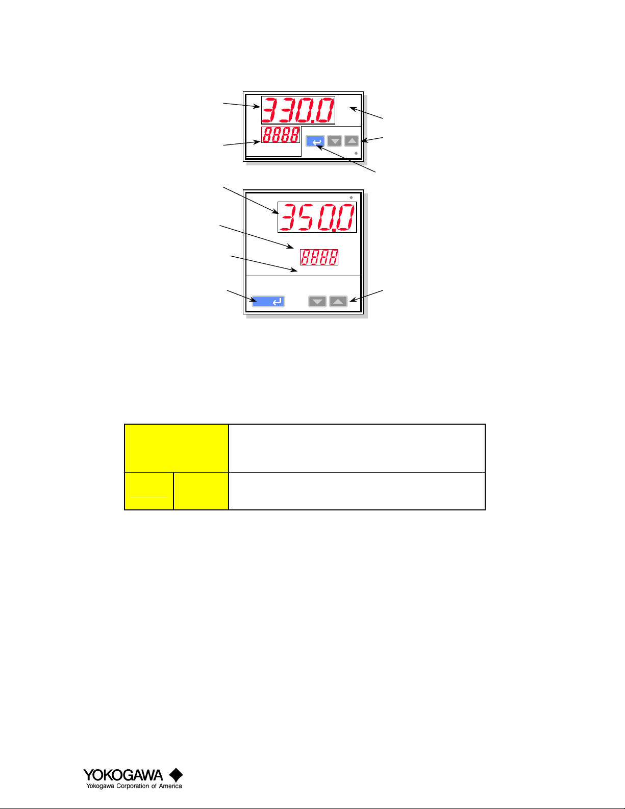
Front Panel
Process Value
parameter type
indicator
Parameter
indicator
Process Value
parameter type
indicator
Parameter
indicator
Alarm LED’s
Set/Enter
key
PV
PV
SET/ENT
SET/ENT
UM330
UM330
AL1 2 3 4
UM350
YOKOGAWA
YOKOGAWA
AL1
2
3
4
Alarm LED’s
Set keys
Set/Enter
key
UM350
Set keys
Key Function
Set/Enter
″″″″
▲
Used to select a parameter or set a parameter. Hold
down for 3 seconds to enter the configuration mode.
▼
Used to change values. Pressing and holding causes the
speed of charging to increase.
Configuration
It is important that the controller be set up in the following manner. Failure to do so could result in incorrect
operation, as changing some parameters will change other related parameters.
1. Apply power (See Wiring Diagram, page 8)
2. Set I.O. parameters
3. Set functional parameters
4. Set operation parameters
5. Operate your process
1
SF UM330/UM350
August 17, 1999
Page 3

Parameter Flow Charts
The UM330/UM350 have a number of software parameters which may or may not be required depending on your
particular application.
A1
A2
A3
A4
PEAK
BOTM
FL
BS
Operating Display
Press the SET/ENT for 3 seconds.
OP.PA STUP
Press the
Press the SET/ENT key (for less than
3 seconds) to move between any of the
parameters.
*
These are the operating
parameters. They may
be set after I/O and
functional parameters.
key
These are the
functional
parameters set
them second.
These are the
input/output
parameters.
Set them first.
Enter the
password
FUNC I/O
AL1
AL2
AL3
AL4
HY1
HY2
HY3
HY4
P.SL
BPS
PRI
STP
DLN
ADR
RP.T
TEST
*
*
*
*
*
*
*
*
IN
UNIT
RH
RL
SDP
SH
SL
RJC
BSL
RET
RTH
RTL
DIS
C.S1
C.S2
C.S3
C.S4
LOCK
PWD
* Available on units with options.
2
SF UM330/UM350
August 17, 1999
Page 4

SF UM330/UM350
August 17, 1999
Input/Output I/O Menu
Type Symbol
IN
UNIT
RH
RL
SDP
SH
SL
3
RJC
BSL
Setup parameters
RET
RTH
RTL
DIS
C.S1
CS2
C.S3
C.S4
LOCK
PWD
Input type
Input unit selection
Range high
Range low
Scale decimal point selection
Scale high (displays when voltage input
is selected)
Scale low
Reference junction compensation
Burnout selection
Retransmission type
Retransmission high
Retransmission low
Digital input s election
Custom SELECT display 1 selection
Custom SELECT display 2 selection
Custom SELECT display 3 selection
Custom SELECT display 4 selection
Key lock
Password
Description
Select from table I
ΕF, ΕC
Thermocouple and RTD: Decimal point
position of instrument range is fixed
(cannot be changed.) DC voltage: 0 to 3
DC voltage: -1999 to 9999
OFF, ON
0 (OFF); 1 (upscale); 2 (down scale)
1: PV; 4: LPS (Power supply for sensor)
EU (0.0 to 100.0%) however, RTL<RTH
0: OFF
1: Resets peak/bottom when DI1 is on.
Custom SELECT display definition;
Allows the operator access to any selected
parameters.
OFF; Parameter changes prohibited; 2:
Holding down SET/ENT key 3 seconds
prohibited; 3.
0: OFF
1 to 9999
Setting range
Default value
1
ΕC
Maximum of
instrument range
Minimum of
instrument range
Location of decimal
point for scale range;
DC voltage 1
When DC voltage is
selected: 100.0
When DC voltage is
selected: 0.0
ON
1
1
RH
RL
OFF
OFF
OFF
OFF
OFF
0
This sets the type of sensor input connected to the controller,
such as a type K thermocouple, 100 Ω RTD or 1-5 VDC signal.
Any range may be selected from table 1.
Select from ΕF or ΕC look up tables for thermocouples and
RTD=s only. Not used for linear inputs.
Maximum/minimum of selected range for thermocouples and
RTD=s. This will default to the range listed in table 1 but may
be set to any number within the setting range. For DCV inputs
this is used to set the voltage-input range. All within the
measurement range are acceptable.
This selects the number of decimal places used for instrument
scaling. 0: limits -1999 to 9999, 1: limits -199.9 to 999.9, 2:
limits -19.99 to 99.99, 3: limits -1.999 to 9.999.
For DCV inputs only. Allows setting of properly scaled units
such as for flow, temperature, level and pH applications. If 1-5
VDC represents 0 to 250.0 set SDP = 1, SH = 250.0 , and SL =
0.0
The RJC must be Αon≅ for thermocouples inputs to read
properly; Αoff≅ for multi thermocouple connections such as for
thermocouple bucking. RJC is not used for RTD or DCV
applications.
Burnout selection determines which way the PV will drive when
the sens or input circuit is opened. 1 will cause PV to drive to
maximum of range and display burnout. 2 will cause PV to
drive to minimum of range and display burnout.
Selects what is retransmitted to a recorder or other analog
device or whether loop power supply is to be used.
The maximum and minimum values for the retransmitted signal.
Up to 4 parameters may be set that operator level personnel may
need to access. Use the CS# in this manual or appendix 3 in the
IM. Ente r any address and the assigned parameter will appear
by pressing SET/ENT during normal operation.
Restricts access to various functions by locking out certain keys.
Password prohibits access to setup menus (I/O and functional)
for those who don t know the password.
Explanation
CS#
1201
1202
1204
1205
1206
1207
1208
1210
1209
1013
1014
1015
932
1036
Page 5

August 17, 1999
Functional (Func) Menu
Type
4
Note 1: These parameters will be displayed on the models with optional specifications.
The parameters in the table below are displayed in the ΑI/O≅ setting scree sub menu for setup parameters.
* See additional information in appendix, Page 8.
Symbol
AL1
AL2
AL3
AL4
HY1
HY2
HY3
HY4
P.SL
Setup Parameters
BPS
PRI
STP
DLN
ADR
RP.T
Description
Alarm 1 type
Alarm 2 type
Alarm 3 type
Alarm 4 type (see note 1)
Alarm 1 hysteresis
Alarm 2 hysteresis
Alarm 3 hysteresis
Alarm 4 hysteresis (see note
1)
Protocol selection (see note 1)
Communication speed (see
note 1)
Parity (see note 1)
Stop bit (see note 1)
Data length (see note 1)
Address (see note 1)
Minimum res ponse time (se e
note 1)
Off, 1, 2, 9, 10, 11, 12, 19, 20, 21, and 22
EUS (0.0 to 100.0%)
0: Personal computer linked communication
1: Personal computer linked communication
(sum checked)
2: Ladder communication
0: 600, 1: 1200, 2: 2400, 3: 4800, 4:9600
0: None, 1: Even 2: Odd
1, 2
Other than 7 or 8 (personal computer link)
1 to 99; however the maximum number of units
that can be connected is 31
0 to 10x10ms
Setting Range
Default value
EUS (0.5%)
1
2
1
1
0
4
1
1
8
1
0
Sets the type of alarm action desired as described in table II.
Sets the dead band or hysteresis of the alarms to avoid relay chattering or frequent
on/off/on/off activation. These are set in Engineering units.
Protocol selection - prompt appears only for units with communications option. Choices:
0: Connection to computer, basic module or touch screen.
1: Same as 0 when driver was written to use sum check capability. Consult driver
developer.
2: Direct connection to devices that support special BCD protocol such as Mitsubishi
Melsec PLC and some Yokogawa devices.
In most cases these communications parameters do not need to be adjusted other than the
address. Consult the developer of the driver or software package for the exact requirements.
Explanation
CS#
915
916
917
918
919
920
921
922
1247
1248
1249
1250
1251
1252
1253
SF UM330/UM350
Page 6

August 17, 1999
Operating Parameters
Type
Note 1: These parameters will be displayed on the models with optional specifications.
The parameters in the table below are displayed in the ΑI/O≅ setting scree sub menu for setup parameters.
* See additional information in appendix, Page 8.
5
Symbol
A1
A2
A3
A4
PEAK
BOTM
FL (*)
BS
Operating parameters
Setpoint value for alarm 1
Setpoint value for alarm 2
Setpoint value for alarm 3
Setpoint value for alarm 4 (see note 1)
Max value
Min value
PV inp ut filter
PV input bias
Description
Alarm for process variable value and setpoint
value: EU (-100.0 to 100.0%)
Deviation alarm: EUS (-100.0 to 100.0%)
Output value alarm: -5.0% to 105.0%
Displa y only
Displa y only
OFF, 1 to 120 sec.
EUS (-100.0 to 100.0%)
Setting range
Alarm fo r proc ess v aria ble valu e and
setpoint value: EU: (100.0%) Other
proce ss variable values and setp oint values:
EU (0.0%) Deviation alarm: EUS (0.0%)
OFF
EUS (0.0%)
Default value
This is the set poin t fo r yo ur a larms , and is se t in t he e nginee ring unit s us ed
(like ΕF)
Displa y max va lue o f inpu t since la st r ese t.
Displa ys min va lue o f inpu t sin ce la st r ese t.
The filt er will set tle dow n an e rra tic or b usy P V disp lay. Use t he smallest
filter to get the smooth result. Note: Excessive filter can be dangerous.
The bia s func tio n will co rrect t he PV rea ding for p oo r se nsor placement or
sensor errors. Use it to co rrect the reading to the value you want to read.
Explanation
CS#
231
232
233
234
235
236
244
243
SF UM330/UM350
Page 7

Table I - Input Selection
Input
Thermocouple
RTD
DC Voltage
Type
K
T
B
S
R
N
E
L (DIN)
U (DIN)
W (DIN)
Platinel 2
PR20-40
W97Re3W75Re25
Jpt100
Pt100
-10.00 to
20.00mV
0.0 to
100.0mV
0.400 to
2.000V
1.000 to
5.000V
0.000 to
2.000V
0.00 to
10.00V
Measurement range (ΕΕΕΕC) Measurement range (ΕΕΕΕF)
-200 to 1370ΕC
-199.9 to 999.9ΕC
-199.9 to 500.0ΕC
J
-199.9 to 999.9ΕC
-199.9 to 400.0ΕC
0.0 to 400.0ΕC
0 to 1800ΕC
0 to 1700ΕC
0 to 1700ΕC
-200 to 1300ΕC
-199.9 to 999.9ΕC
-199.9 to 900.0ΕC
-199.9 to 400.0ΕC
0.0 to 400.0ΕC
0 to 2300ΕC
0 to 1390ΕC
0 to 1900ΕC
0 to 2000ΕC
-199.9 to 500.0ΕC
-150.0 to 150.0ΕC
-199.9 to 640.0ΕC
-199.9 to 500.0ΕC
-150.0 to 150.0ΕC
Display range -1999 to 9999
-300 to 2500ΕF
0 to 2300ΕF
-199.9 to 999.9ΕF
-300 to 2300ΕF
-300 to 750ΕF
-199.9 to 750.0ΕF
32 to 3300ΕF
32 to 3100ΕF
32 to 3100ΕF
-300 to 2400 ΕF
-300 to 1800ΕF
-300 to 1300ΕF
-300 to 750ΕF
-19.9 to 750.0ΕF
32 to 4200ΕF
32 to 2500Ε
32 to 3400ΕF
32 to 3600ΕF
-300 to 1180ΕF
-199.9 to 300.0ΕF
-300 to 1180ΕF
-199.9 to 999.9ΕF
-199.9 to 300.0ΕF
At or above 400ΕC ∀ 0.15% ∀ 1 digit of F.S.
Measuring Accuracy
At or above 0Ε ∀0.1% ∀1 digit of F.S.
below 400ΕC ∀ digit of F.S.
∀0.15% ∀ 1 digit of F.S.
∀0.2% ∀ 1 digit of F.S.
At or above 0ΕC ∀ 0.1% ∀1 digit of F.S.
Below 0ΕC ∀0.2% ∀ 1 digit of F.S.
∀0.1% ∀ 1 digit of F.S.
∀ 0.1% ∀ 1 digit of F.S.
At or above 800ΕC ∀0.5% ∀ 1 digit of F.S.
below 800ΕC not guarante ed
∀0.2% ∀ 1 digit of F.S.
∀0.1% ∀1 digit of F.S.
∀0.2% ∀1 digit of F.S.
∀0.1% ∀ 1 digit of F.S.
∀0.2% ∀ 1 digit of F.S.
∀0.1% ∀ 1 digit of F.S.
Input range code
1
2
3
4
5
6
7
8
9
10
11
12
13
14
15
16
17
18
30
31
35
36
37
55
56
40
41
50
51
6
SF UM330/UM350
August 17, 1999
Page 8

TABLE II - ALARMS
Type of Alarm
Process Variable Alarms
High Level Alarm
Low Leve l Alarm
High Level Alarm
Low Leve l Alarm
Diagnosis Alarms
Self Diagnosis
Fail
Normally Open Closes on Alarm
Normally Open Closes on Alarm
Normally Closed Opens on Alarm
Normally Closed Opens on Alarm
Normally Open Closes on Alarm
Normally Closed Opens on Alarm
Action of Relay
Alarm always Active
1
2
9
10
21
22
Code
Standby on Startup
11
12
19
20
7
SF UM330/UM350
August 17, 1999
Page 9

Appendix
FL - Filter: The input filter will reduce the oscillation or fluctuation of the process value. Use the smallest filter that
accomplishes the desired result.
Wiring Diagram
8
SF UM330/UM350
August 17, 1999
 Loading...