

Page 1

User’ s
Manual
GREEN Series
User ’s Manual
- Detailed Instruction -
IM 05J01B02-01E
IM 05J01B02-01E
5th Edition
Page 2

Page 3

GREEN Series
User’s Manual
- Detailed Instruction -
IM 05J01B02-01E 5th Edition
CONTENTS
Ref.1.1: References Related to PV Input ...................................................Ref. 1-1
Ref.1.1(1) Correcting the PV (1. Using PV input filter and PV input bias)............ Ref. 1-1
Ref.1.1(2) Correcting the PV (2.Using ten-segment linearizer biasing or
approximation)....................................................................................Ref. 1-4
Ref.1.1(3) Square-root extraction of PV ................................................................ Ref. 1-9
Ref.1.1(4) Changing the PV sampling period...................................................... Ref. 1-1 1
Ref.1.1(5) Checking that the changed PV sampling period is appropriate ....... Ref. 1-14
Ref.1.1(6) Correcting the input value from a sensor .......................................... Ref. 1-16
Ref.1.1(7) Using PV tracking function (UT only) .................................................Ref. 1-18
Ref.1.1(8) PV input range adjustment (When the UT/UP mode No. is 6, 7 or
12 only) ..............................................................................................Ref. 1-21
Toc-i
Ref.1.2: References Related to Remote Input......................................... Ref. 1-22
Ref.1.2(1) Setting remote input units, range and scaling................................... Ref. 1-23
Ref.1.2(2) Using square root extraction during remote input ............................ Ref. 1-27
Ref.1.2(3) Using remote setpoint filtering and ratio bias computing ................ Ref. 1-28
Ref.1.2(4)
Tracking target setpoint when switching from remote to local control .
Ref. 1-30
Ref.2.1: References Related to Control Output ........................................Ref. 2-1
Ref.2.1(1) Switching between Direct and Reverse Actions.................................. Ref. 2-2
Ref.2.1(2) Selecting PID Control Mode According to the Operating Condition ..Ref. 2-4
Ref.2.1(3) Using Control Output Limiter ...............................................................Ref. 2-8
Ref.2.1(4) Using Anti-reset Windup (Over-integration Prevention) Function ..... Ref. 2-9
Ref.2.1(5) Using “Super” (Overshoot Prevention) Function..............................Ref. 2-10
Ref.2.1(6) Using “Super2” (Hunting Prevention) Function ................................ Ref. 2-11
Ref.2.1(7) Using Split-signal Computation / Output Function ........................... Ref. 2-13
Ref.2.1(8) Setting Preset Output Values.............................................................. Ref. 2-16
Ref.2.1(9) Placing Control Output in Tracking Mode (for Cascade
Primary-loop Control or Loop Control for Backup) ........................ Ref. 2-18
Ref.2.1(10) Using Shutdown Function ................................................................ Ref. 2-19
Ref.2.2: References Related to Retransmission Output ........................ Ref. 2-20
Ref.2.2(1) Changing the type of retransmission output signal .......................... Ref. 2-21
Ref.2.2(2) Retransmitting Program Pattern 2 (for UP750/UP550 only) .............. Ref. 2-23
Ref.2.2(3) Using the Loop Power Supply Function ............................................ Ref. 2-24
IM 05J01B02-01E 5th Edition : Mar.25,2005-00
Page 4

Toc-ii
Ref.3.1: References Related to Contact Input........................................... Ref. 3-1
Ref.3.1(1) Changing contact input functions for the UT35h/UT32h.................... Ref. 3-2
Ref.3.1(2) Changing contact input functions for the UT450/UT420 .................... Ref. 3-5
Ref.3.1(3) Changing contact input functions for the UT550/UT551/UT520 ......... Ref. 3-9
Ref.3.1(4) Changing contact input functions for the UT750.............................. Ref. 3-14
(4-1): Changing contact input terminal assignments of the UT750 ............ Ref. 3-14
(4-2): Using contact I/O expansion module with the UT750 ...................... Ref. 3-18
(4-3): Using Interrupt-message functions with the UT750 ......................... Ref. 3-20
(4-4): Using Interrupt-operating display functions with the UT750............. Ref. 3-22
Ref.3.1(5) Changing contact input functions for the UP35h ............................. Ref. 3-24
Ref.3.1(6) Changing contact input functions for the UP550 ..............................Ref. 3-26
Ref.3.1(7) Changing contact input functions for the UP750 .............................Ref. 3-29
(7-1): Changing contact input functions for the UP750.............................. Ref. 3-29
(7-2): Using contact I/O expansion module with the UP750 ...................... Ref. 3-34
(7-3): Using Interrupt-message functions with the UP750......................... Ref. 3-36
(7-4): Using Interrupt-operating display functions with the UP750............. Ref. 3-39
Ref.3.2: References Related to Contact Output...................................... Ref. 3-40
Ref.3.2(1) Changing Contact Output Functions for the UT750, UT550, UT551
and UT520 .........................................................................................Ref. 3-41
(1) Single-loop control (UT mode 1).......................................................... Ref. 3-44
(2) Cascade, primary-loop control (UT mode 2)........................................ Ref. 3-45
(3) Cascade, secondary-loop control (UT mode 3) ................................... Ref. 3-45
(4) Cascade control (UT mode 4) ............................................................. Ref. 3-46
(5) Loop control for backup (UT mode 5) .................................................. Ref. 3-46
(6) Loop control with PV switching (UT mode 6) ....................................... Ref. 3-47
(7) Loop control with PV auto-selector (UT mode 7) ................................. Ref. 3-47
(8) Loop control with PV-hold function (UT mode 8).................................. Ref. 3-48
(9) Dual-loop control (UT mode 1 1 ) .......................................................... Ref. 3-48
(10) Temperature and humidity control (UT mode 12)............................... Ref. 3-48
(1 1) Cascade control with two universal inputs (UT mode 13)................... Ref. 3-49
Loop control with PV switching and two universal inputs (UT mode 14) ..
(12)
Loop control with PV auto-selector and two universal inputs (UT mode 15).
(13)
(14) Custom computation control (UT mode 21) ....................................... Ref. 3-49
Ref.3.2(2) Changing Contact Output Functions in the UP750 and UP550 ........Ref. 3-50
(1) Single-loop control (UP mode 1) ......................................................... Ref. 3-51
(2) Cascade, primary-loop control (UP mode 2)........................................ Ref. 3-52
(3) Cascade control (UP mode 4) ............................................................. Ref. 3-53
(4) Loop control with PV switching (UT mode 6) ....................................... Ref. 3-53
(5) Loop control with PV auto-selector (UP mode 7) ................................. Ref. 3-54
(6) Dual-loop control (UP mode 1 1) This function is for the UP750 only..... Ref. 3-55
(7) Temperature and humidity control (UP mode 12)
This function is for the UP750 only . .......................................... Ref. 3-55
Ref. 3-49
Ref. 3-49
IM 05J01B02-01E
5th Edition : Mar.25,2005-00
Page 5

Toc-iii
(8) Cascade control with two universal inputs (UP mode 13) .................... Ref. 3-56
Loop control with PV switching and two universal inputs (UP mode 14) ....
(9)
(10)
Loop control with PV auto-selector and two universal inputs (UP mode 15).
(1 1) Custom computation control (UP mode 21) ....................................... Ref. 3-56
Ref.3.2(3) Using the I/O Expansion Module with UT750 and UP750 .................. Ref. 3-57
Ref.3.3: References Related to Alarms ................................................... Ref. 3-62
Ref.3.3(1) Setting Alarm T rigger Conditions....................................................... Ref. 3-63
Ref.3.3(2) Setting Alarm hysteresis ON/OFF range............................................ Ref. 3-65
Ref.3.3(3) Using the alarm timer (Control stable signal event) .......................... Ref. 3-67
Ref.3.3(4) Using the sensor ground alarm .......................................................... Ref. 3-70
Ref.3.3(5) Using the heater burnout alarm (UT35u and UT32u only)................. Ref. 3-75
Ref.3.4: References Related to Instrument Alarms and Events............. Ref. 3-77
Ref.3.4(1) Using Instrument Alarms .................................................................... Ref. 3-78
Ref.3.4(2) Setting the Operating Conditions of Instrument Alarms................... Ref. 3-83
Ref.3.4(3) Setting Hysteresis (On-off Bandwidth) of an Instrument Alarm ....... Ref. 3-84
Ref.3.4(4) Using the Sensor Ground Alarm.........................................................Ref. 3-86
Ref.3.4(5) Using PV Events ..................................................................................Ref. 3-90
Ref.3.4(6) Using Time Events ..............................................................................Ref. 3-97
Ref.3.4(7) Using Local Events ...........................................................................Ref. 3-101
Ref. 3-56
Ref. 3-56
Ref.4.1: References Related to T arget Setpoints...................................... Ref. 4-1
Ref.4.1(1) Using Multiple T arget Setpoints (8 Max.).............................................. Ref. 4-2
Ref.4.1(2) Selecting PID selection method (T arget SP selection, Zone PID or
Selection by specified PID number)................................................. Ref. 4-10
Ref.4.1(3) Limiting Changes in T arget Setpoints................................................ Ref. 4-17
Ref.4.1(4) Setting ramp grades when switching between target setpoints ......Ref. 4-18
Ref.5.1: References Related to Segment Operation................................. Ref. 5-1
Ref.5.1(1) Selecting Segment time between Time and Ramp time ...................... Ref. 5-1
Ref.5.1(2) Selecting PID control between Zone and Segment .............................Ref. 5-7
Ref.5.2: References Related to Program Setup ...................................... Ref. 5-10
Ref.5.2(1) Selecting Program Start Condition ....................................................Ref. 5-10
Ref.5.2(2) Using the Delayed Start Timer for Programmed Operation .............. Ref. 5-17
Ref.5.2(3) Selecting Segment-end Condition .....................................................Ref. 5-18
Ref.5.2(4) Using the Wait Function......................................................................Ref. 5-24
Ref.5.2(5)
Ref.5.2(6) Using the Repeat Functions ...............................................................Ref. 5-34
Ref.5.2(7) Using the Advance Functions.............................................................Ref. 5-37
Ref.5.2(8) Signal Output at Program end ............................................................Ref. 5-39
Ref.5.2(9) Operation in Local Mode (with Constant T arget Setpoint) ................ Ref. 5-41
Ref.5.2(10) Starting the Program Operation at Any Segment ............................ Ref. 5-44
Ref.5.2(11) Operation with Linked Program Patterns (Pattern-link) .................. Ref. 5-46
Using the Hold Functions (Changing Segment Setpoint in Hold Status)
Ref. 5-30
IM 05J01B02-01E 5th Edition : Mar.25,2005-00
Page 6

Toc-iv
Ref.5.3: Handy Features for Creating and Editing Programs................. Ref. 5-48
Ref.5.3(1) Checking the T otal Number of Unused Segments.............................Ref. 5-48
Ref.5.3(2) Checking the number of segments in a specific Program Pattern ... Ref. 5-50
Ref.5.3(3) Checking the number of all unused events ....................................... Ref. 5-51
Ref.5.3(4) Copying Program Patterns ................................................................. Ref. 5-53
Ref.5.3(5) Deleting Program Patterns .................................................................Ref. 5-55
Ref.5.3(6) Adding (Inserting)/Deleting segments in Program Patterns............. Ref. 5-57
Ref.6.1: References Related to Displays................................................... Ref. 6-1
Ref.6.1(1) Using SELECT Displays........................................................................ Ref. 6-2
Ref.6.1(2) Changing Contents of Deviation Trend Display (for UP750, UP550
and UT750 only) .................................................................................. Ref. 6-5
Ref.6.1(3) Changing Deviation Display Range of Deviation Monitor
(for UT750, UT550, UT551 and UT450 only) .......................................Ref. 6-7
Ref.7.1: References Related to Security ...................................................Ref. 7-1
Ref.7.1(1) Setting a password to prevent unauthorized changes to
setup parameters................................................................................ Ref. 7-1
Ref.7.1(2) Using the keylock function to prevent unauthorized key operation... Ref. 7-2
Ref.8.1: Outline of Registers and I - relays................................................Ref. 8-1
Ref.8.1(1) Outline of Registers and I - relays ........................................................Ref. 8-2
Ref.8.1(2) D-register Outline and D-register Map .................................................Ref. 8-3
UP750,UP550 D-register Map.................................................................... Ref. 8-4
UP35 D-register Map .............................................................................. Ref. 8-8
UT750, UT55, UT520 D-register Map.................................................... Ref. 8-12
UT450,UT420 D-register Map .................................................................. Ref. 8-16
UT35, UT32 D-register Map .............................................................. Ref. 8-19
Ref.8.1(3) B-register Outline and B-register Map ...............................................Ref. 8-23
UP750,UP550 B-register Map.................................................................. Ref. 8-24
Ref.8.1(4) I-relay Outline and I-relay Map ............................................................ Ref. 8-26
UP750, UP550 I-relay Map...................................................................... Ref. 8-28
Ref.8.1(5) I-relay Timer setting............................................................................. Ref. 8-33
Revision Information ............................................................................................ i
IM 05J01B02-01E
5th Edition : Mar.25,2005-00
Page 7
<Toc> <Ref. 1.1: References Related to PV Input>
Ref.1.1: References Related to PV Input
Ref. 1-1
IMPORTANT
UP750
UP750-
Note: The functions discussed in this section apply to all the models of UT and UP series.
UP550
UP550-
However, some of the functions are unavailable with certain models.
Such models, if any, will be clearly noted in each of the following items from (1) to (8).
UP35
UP35-
: Applicable models of this section
UT750
UT750-
UT5
UT55-
UT520-
UT40
UT450-
UT420-
UT3
UT35-
UT32-
These sections provide references related to PV input, such as PV correction, listed below.
Only read the following descriptions if necessary and carry out the required operation.
(1) Correcting the PV (1. Using PV input filter and PV input bias)
(2) Correcting the PV (2. Using ten-segment linearizer biasing or approximation)
(3) Square-root extraction of PV
(4) Changing the PV sampling period
(5) Checking that the changed PV sampling period is appropriate
(6) Correcting the input value from a sensor
(7) Using PV tracking function (UT only)
(8) PV input range adjustment (when the UT/UP mode No. is 6, 7 or 12 only)
UM3
None
<<Ref.1.1: References Related to PV Input>>
Ref.1.1(1) Correcting the PV (1. Using PV input filter and PV input bias)
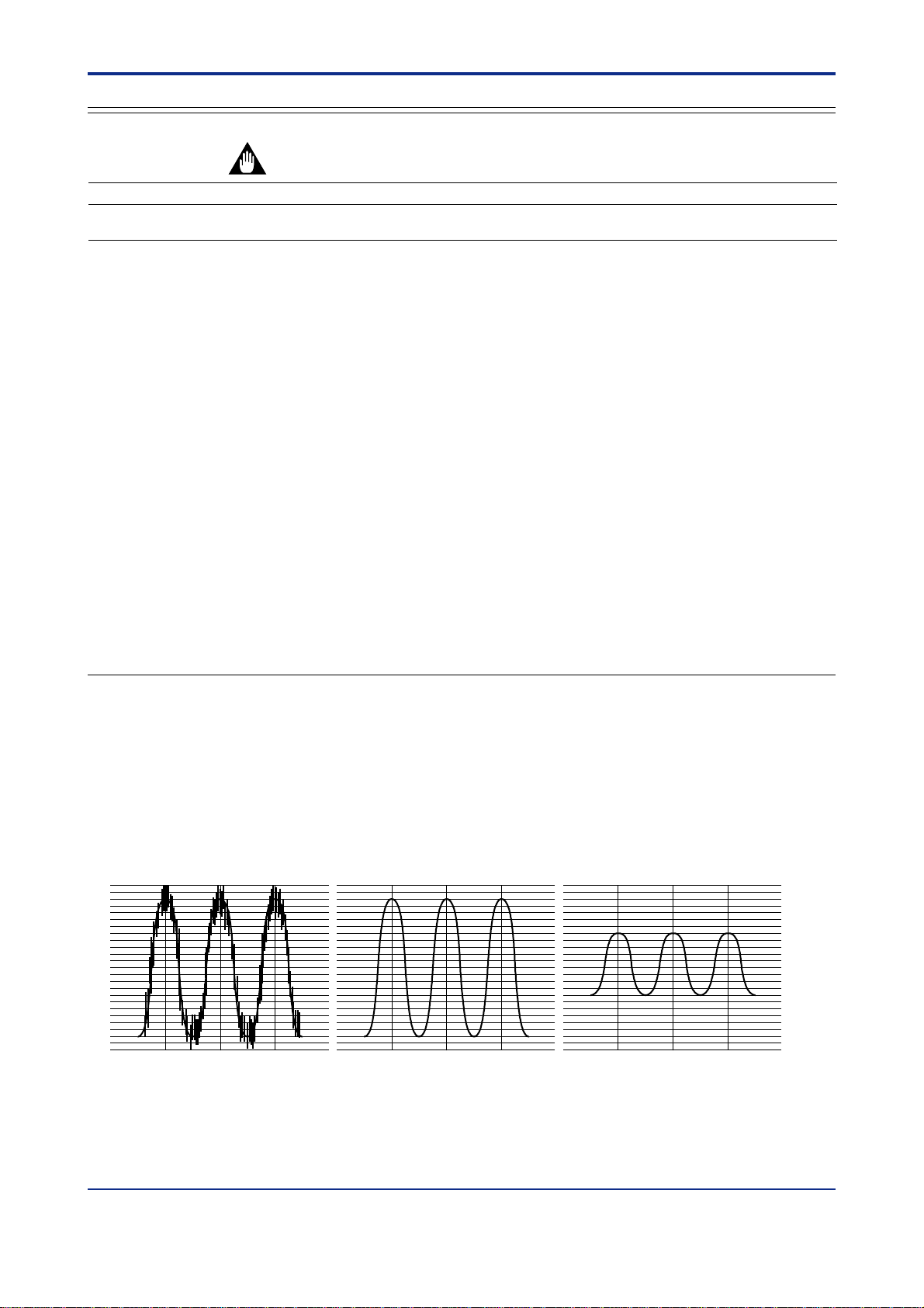
Filtering and biasing functions are available with all the UT/UP series models.
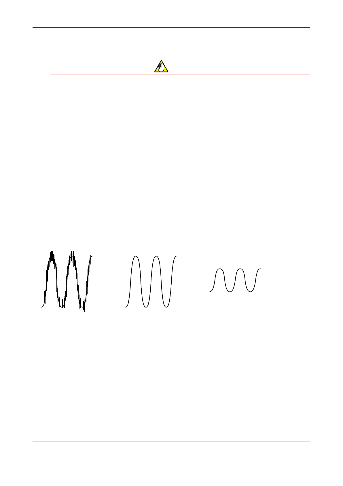
■ PV input filtering can be used to remove noise from a PV input that contains high frequency noise,
such as flow rate and pressure signals.
The PV input filter provides first-order-lag computation.
Setting a larger time constant (as a parameter value) can increase the amount of noise removed.
This filtering is also used to improve controllability and for phase compensation.
The time constant of the PV filter is offered as an operating parameter and can be changed during operation.
Actual input With a small time constant With a large time constant
Fig. 1-1-1
IM 05J01B02-01E 5th Edition : Mar.25,2005-00
Page 8
<T oc> <Ref. 1.1: References Related to PV Input>
Ref. 1-2
■ PV input biasing adds a constant bias value to the PV input value, and the result is used for the
controller display and control computation.
PV input value PV value inside the controllerPV input bias
+
=
In some cases, the measured value is smaller than the actual value by a constant amount due to the physical
circumstances at the sensor point.
For example, the ambient temperature inside a furnace is often measured instead of the material’s temperature.
In such cases, add a constant value for biasing.
When the PV value is within the allowable accuracy range but there is a dispersion in PV readings between other
equipment, it is possible to use this function for fine adjustment.
● The following parameters are used.
• Operating parameters (Operation-related parameters): BS and FL
UP750
UP550
UT750
Code
BS
FL
UT5
UT40
Code
(BS) (BS)
(FL) (FL)
UP35
UT3
Code
Description
PV input bias
PV input filter
Setting range
-100.0 to 100.0% of
input range span
OFF or 1 to 120 s
Default
0.0% of input
range span
OFF
(No filtering)
D-register No.
243,
273(Note1)
244,
274(Note2)
Note1: For dual-loop control of UP750 and UT750, the D-register number of loop-2 BS is 273.
Note2: For dual-loop control of UP750 and UT750, the D-register number of loop-2 FL is 274.
T o set the parameters, carry out the following steps.
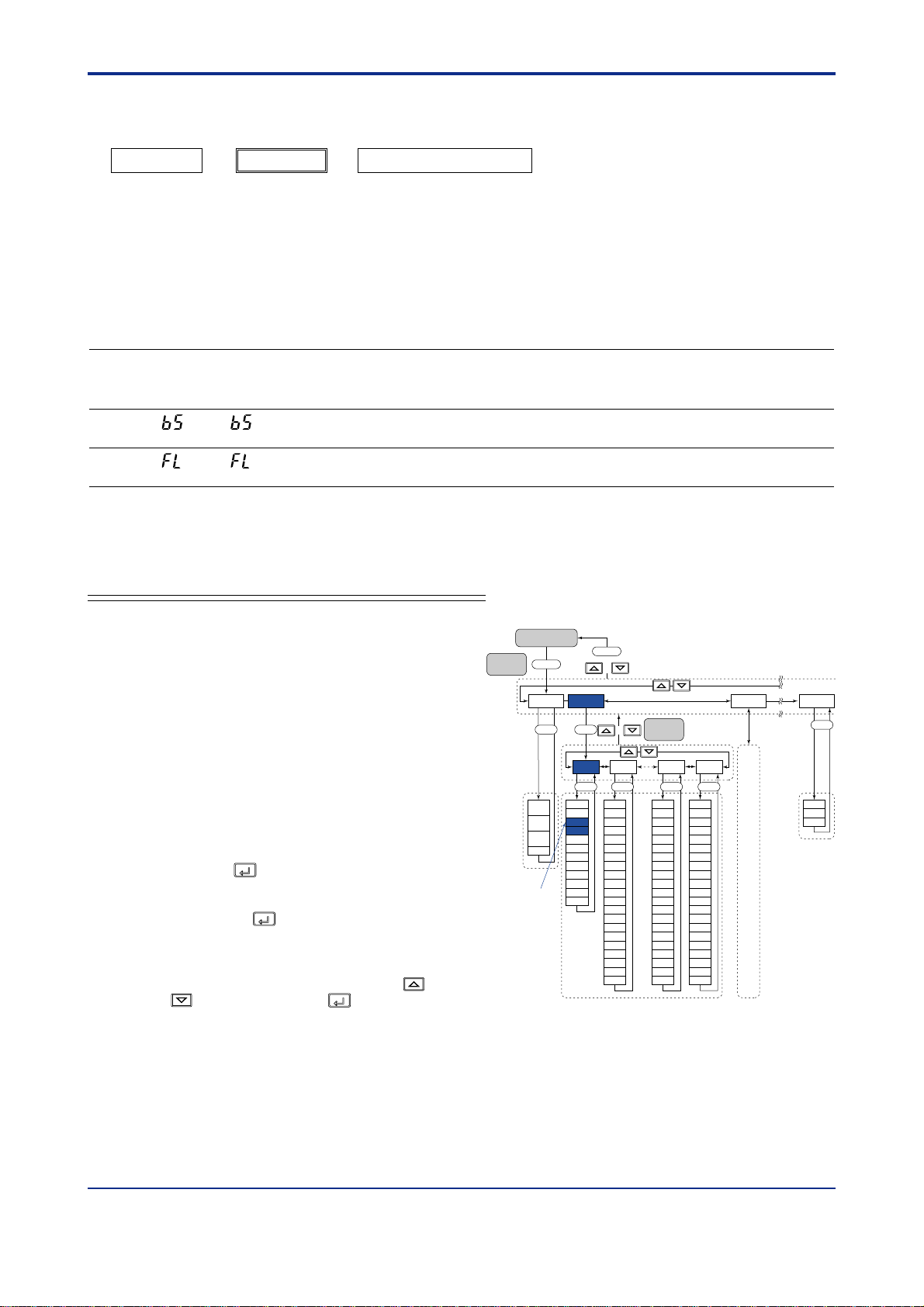
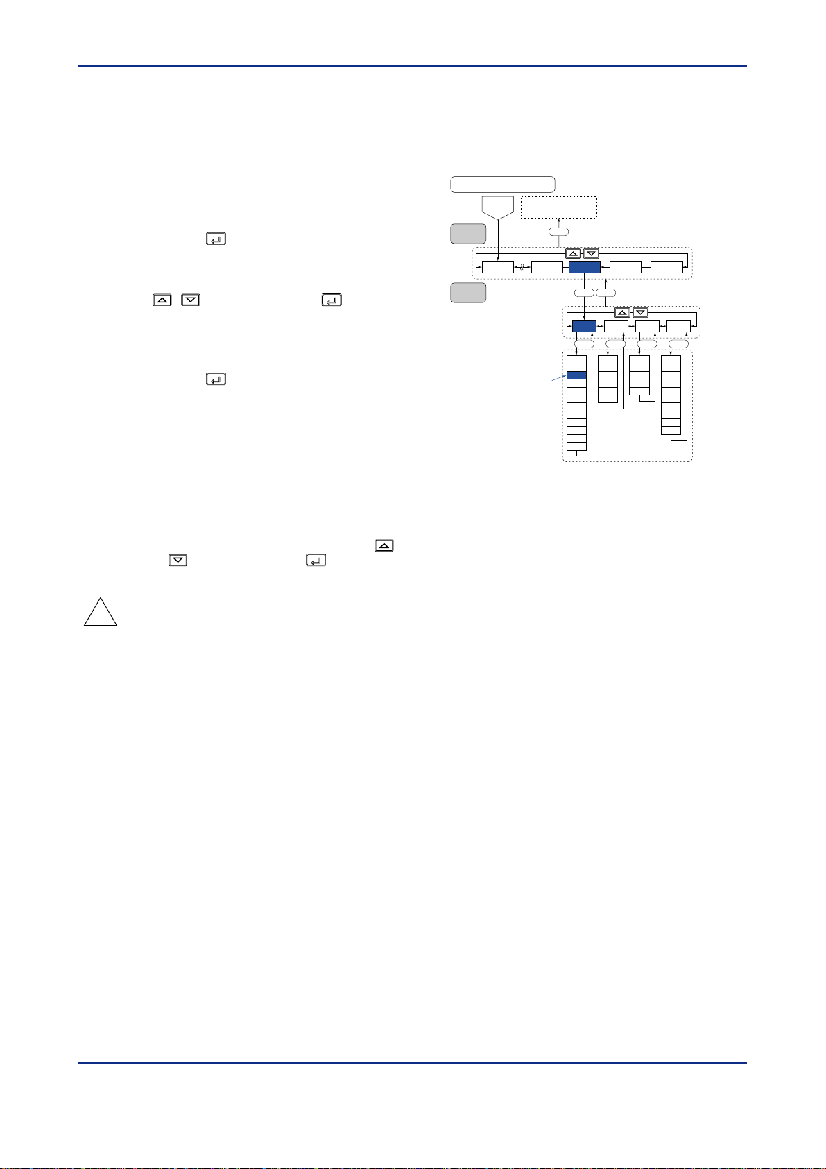
■ For UP750, UP550, UT750, UT550, UT551, and UT520
Here we explain how to display the parameter setting
display and to change the parameter values. Before
carrying out these operations be sure to refer to the
User’s Manuals Initial Settings and Parameter Map of
the controller.
The parameter map is very helpful in finding the path to
the setting display for a particular parameter.
1: Referring to the User’s Manual above, display
the operating parameter main menu [LP1]
(Note1).
Then, display the submenu [P AR].
Note1: If the UP/UT mode has been set for using loop-2 or the
secondary loop, also set the corresponding parameters under
the main menu [LP2] in the same way.
2: Press the
SET/ENT
key 3 times* to display the PV
input bias parameter BS.
* Depends on the controller mode.
Pressing the
SET/ENT
key one more time displays
the PV input filter parameter FL.
3: In each of these parameter setting displays,
adjust the parameter value using the
keys, then press the
SET/ENT
key to register it.
/
Parameter map (UT550/UT520)
Operating display
Main
SET3S
menu
MODE
SET
MOD
(C.A.M)
MOD
(R/L)
MOD
(S/R)
SPN
“BS”
SET3S
or
+
LP1 LP2 USR
1.SP
1.A1
1.A2
1.A3
1.A4
1.P
1.D
1.OH
1.OL
1.MR
1.H
1.DR
1.Pc
1.Ic
1.Dc
1.Hc
1.DB
1.RP
1.PO
1.Oc
Sub menu
+
SET
1.I
7.SP
7.A1
7.A2
7.A3
7.A4
7.P
7.D
7.OH
7.OL
7.MR
7.H
7.DR
7.Pc
7.Ic
7.Dc
7.Hc
7.DB
RHY
7.PO
7.Oc
SET
SET
8.SP
8.A1
8.A2
8.A3
8.A4
8.P
7.I
8.I
8.D
Same
8.OH
8.OL
8.MR
8.H
8.DR
8.Pc
8.Ic
8.Dc
8.Hc
8.DB
RDV
8.PO
8.Oc
as
LP1
SET
PAR 1.PID 7.PID 8.PID
SET
AT
SC
BS
FL
UPR
DNR
RT
RBS
RFL
ORB
ORH
ORL
SET
U1
U2
U3
IM 05J01B02-01E 5th Edition : Mar.25,2005-00
Page 9
<Toc> <Ref. 1.1: References Related to PV Input>
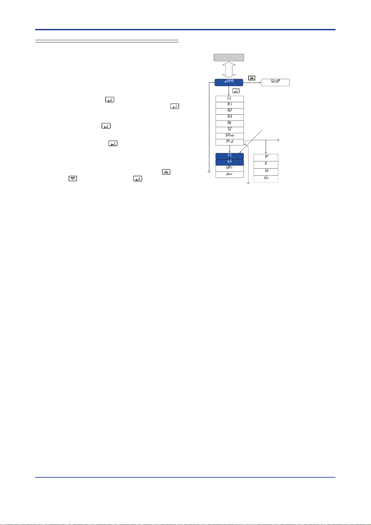
■ For UP35, UT450, UT420, UT35, and UT32
Here we explain how to display the parameter setting
display and to change the parameter values. Before
carrying out these operations be sure to refer to the
User’s Manuals Initial Settings and Parameter Map of
the controller.
Parameter map (UT350/UT320/UT351/UT321)
Operating display
SET
3S
The parameter map is very helpful in finding the path
to the setting display for a particular parameter.
1: With the operating display shown, press and
hold down the
SET/ENT
key for 3 seconds or
longer to call up [oP.P A]. Then press the
SET/ENT
SET/ENTSET/ENT
key repeatedly (Note) until the PV filter
parameter FL appears.
Pressing the
the PV input bias parameter BS.
Note: The number of times a
depending on the model of the controller. See the parameter
map of your controller.
SET/ENT
key one more time displays
SET/ENT
key is pressed differs
PID = 0
“FL”
PID = 1
2: In each of these parameter setting displays,
adjust the parameter value using the
keys, then press the
SET/ENT
key to register
/
it.
Ref. 1-3
IM 05J01B02-01E 5th Edition : Mar.25,2005-00
Page 10

<T oc> <Ref. 1.1: References Related to PV Input>
Ref. 1-4
<<Ref.1.1: References Related to PV Input>>
Ref.1.1(2) Correcting the PV (2.Using ten-segment linearizer biasing or approximation)
Ten-segment linearizer biasing and approximation are available with UP750, UP550, UT750, UT550, UT551, and
UT520.
Whether to use the biasing or approximation function is specified by the parameter 1.PMD (Note), which is set to
specify
As shown in the following “Operating parameters (Ten-segment linearizer input parameters)” table, the setting
display of parameter 1.PMD is located after the ten-segment linearizer input 1 to 1 1 and ten-segment linearizer
output 1 to 1 1.
Note: •“1.PMD” is the parameter for UP750, UP550, and UT750.
→ For how to set the parameters required for the functions discussed here, see “■ Setting the Required Param-
ten-segment linearizer biasing at the time of shipping.
•“1.MD” is the parameter for UT550, UT551 and UT520.
•“2.PMD” can also be used if the UP/UT mode is set for using loop-2 or the secondary loop.
eters” in the end of this subsection.
IM 05J01B02-01E 5th Edition : Mar.25,2005-00
Page 11
<Toc> <Ref. 1.1: References Related to PV Input>
■ Ten-segment Linearizer Biasing
This function is used to correct an input signal affected by sensor deterioration. The corrected values (b) are
obtained by adding the corresponding bias values to each of the 1 1 points of optionally set input values (a).
The input values used to configure the ten-segment linearizer are set with parameters 1.a1 to 1.a1 1 (Note). The
bias values (b-axis) for each of the input values (a) are set with parameters 1.b1 to 1.b1 1 (Note).
Note: • 1.a1 to 1.a11 and 1.b1 to 1.b1 1 are the parameters for UP750, UP550, and UT750.
• 1.A1 to 1.AB and 1.B1 to 1.BB are the parameters for UT550, UT551 and UT520.
• If the UP/UT mode is set for using loop-2 or the secondary loop, “2.a1 to 2.a11 and 2.b1 to 2.b11,” and “2.A1 to 2.AB and 2.B1 to
2.BB” can also be used.
Output
(b)
Corrected value
(the sum of actual
input and bias
values)
n.b4
Actual input
Ten-segment linearizer
bias
Ref. 1-5
n.a2 n.a4 Input
(a)
Fig. 1-1-2 T en-segment Linearizer Biasing
■ Ten-segment Linearizer Approximation
This function is used when the input signal and the required measurement signal have a non-linear relationship.
For example, when trying to obtain the volume from a sphere tank level.
As shown in the figure below, the output values (b) can be optionally set to 11 points of the optionally set input
values (a).
The input values used to configure the ten-segment linearizer are set with parameters 1.a1 to 1.a1 1 (Note). The
corrective values (b-axis) of ten-segment linearizer approximation for each of the input values (a) are set with
parameters 1.b1 to 1.b1 1 (Note).
Note: • 1.a1 to 1.a11 and 1.b1 to 1.b1 1 are the parameters for UP750, UP550, and UT750.
• 1.A1 to 1.AB and 1.B1 to 1.BB are the parameters for UT550, UT551 and UT520.
• If the UP/UT mode is set for using loop-2 or the secondary loop, “2.a1 to 2.a11 and 2.b1 to 2.b11” and “2.A1 to 2.AB and 2.B1 to 2.BB”
can also be used.
Output
(b)
Ten-segment
linearizer approximation
Input
(a)
Fig. 1-1-3 T en-segment Linearizer Approximation
IM 05J01B02-01E 5th Edition : Mar.25,2005-00
Page 12
<T oc> <Ref. 1.1: References Related to PV Input>
● The following parameters are used.
• Operating parameters (T en-segment Linealizer Parameters)
UP750
UP550
UT750
Code
1.a1
2.a1
1.b1
2.b1
1.a2
2.a2
1.b2
2.b2
1.a3
2.a3
1.b3
2.b3
1.a4
2.a4
1.b4
2.b4
1.a5
2.a5
1.b5
2.b5
1.a6
2.a6
1.b6
2.b6
1.a7
2.a7
1.b7
2.b7
UT5
Code
(1.A1)
2.A1 (for 2nd loop)
(1.B1)
2.B1 (for 2nd loop)
(1.A2)
2.A2 (for 2nd loop)
(1.B2)
2.B2 (for 2nd loop)
(1.A3)
2.A3 (for 2nd loop)
(1.B3)
2.B3 (for 2nd loop)
(1.A4)
2.A4 (for 2nd loop)
(1.B4)
2.B4 (for 2nd loop)
(1.A5)
2.A5 (for 2nd loop)
(1.B5)
2.B5 (for 2nd loop)
(1.A6)
2.A6 (for 2nd loop)
(1.B6)
2.B6 (for 2nd loop)
(1.A7)
2.A1 (for 2nd loop)
(1.B7)
2.B7 (for 2nd loop)
Description Setting range
Ten-segment
linearizer 1 input-1
(Note 1)
Ten-segment
linearizer 1 output-1
(Note 1)
Ten-segment
linearizer 1 input-2
(Note 1)
Ten-segment
linearizer 1 output-2
(Note 1)
Ten-segment
linearizer 1 input-3
(Note 1)
Ten-segment
linearizer 1 output-3
(Note 1)
Ten-segment
linearizer 1 input-4
(Note 1)
Ten-segment
linearizer 1 output-4
(Note 1)
Ten-segment
linearizer 1 input-5
(Note 1)
Ten-segment
linearizer 1 output-5
(Note 1)
Ten-segment
linearizer 1 input-6
(Note 1)
Ten-segment
linearizer 1 output-6
(Note 1)
Ten-segment
linearizer 1 input-7
(Note 1)
Ten-segment
linearizer 1 output-7
(Note 1)
-66.7% to 105.0% of
PV input range
-66.7% to 105.0% of
PV input range span (Note 2)
-66.7% to 105.0% of
PV input range
-66.7% to 105.0% of
PV input range span (Note 2)
-66.7% to 105.0% of
PV input range
-66.7% to 105.0% of
PV input range span (Note 2)
-66.7% to 105.0% of
PV input range
-66.7% to 105.0% of
PV input range span (Note 2)
-66.7% to 105.0% of
PV input range
-66.7% to 105.0% of
PV input range span (Note 2)
-66.7% to 105.0% of
PV input range
-66.7% to 105.0% of
PV input range span (Note 2)
-66.7% to 105.0% of
PV input range
-66.7% to 105.0% of
PV input range span (Note 2)
Default D-register
0.0% of PV input range
0.0% of PV input range
span (Note 2)
0.0% of PV input range
0.0% of PV input range
span (Note 2)
0.0% of PV input range
0.0% of PV input range
span (Note 2)
0.0% of PV input range
0.0% of PV input range
span (Note 2)
0.0% of PV input range
0.0% of PV input range
span (Note 2)
0.0% of PV input range
0.0% of PV input range
span (Note 2)
0.0% of PV input range
0.0% of PV input range
span (Note 2)
Ref. 1-6
No.
726
751
727
752
728
753
729
754
730
755
731
756
732
757
733
758
734
759
735
760
736
761
737
762
738
763
739
764
IM 05J01B02-01E 5th Edition : Mar.25,2005-00
Page 13
<Toc> <Ref. 1.1: References Related to PV Input>
Ref. 1-7
UP750
UP550
UT750
Code
1.a8
2.a8
1.b8
2.b8
1.a9
2.a9
1.b9
2.b9
1.a10
2.a10
1.b10
2.b10
1.a11
2.a11
1.b11
2.b11
1.PMD
2.PMD
Note1: These parameters are used for loop-2 when the UP/UT mode is set for using loop-2 or the secondary loop.
Note2: As shown in the table,
UT5
Description Setting range
Code
Ten-segment
(1.A8)
2.A8 (for 2nd loop)
(1.B8)
2.B8 (for 2nd loop)
(1.A9)
2.A9 (for 2nd loop)
(1.B9)
2.B9 (for 2nd loop)
(1.AA)
2.AA (for 2nd loop)
(1.BA)
2.BA (for 2nd loop)
(1.AB)
2.AB (for 2nd loop)
(1.BB)
2.BB (for 2nd loop)
(1.MD)
2.MD (for 2nd loop)
biasing. In this mode, the ten-segment linearizer output parameters are bias values; therefore, their setting ranges at the time of
shipping are -66.7 to 105.0% of measurement range span.
If the ten-segment linearizer mode is
parameters will be -66.7 to 105.0% of the PV input range (corrective values for approximation).
linearizer 1 input-8
(Note 1)
Ten-segment
linearizer 1 output-8
(Note 1)
Ten-segment
linearizer 1 input-9
(Note 1)
Ten-segment
linearizer 1 output-9
(Note 1)
Ten-segment
linearizer 1 input-10
(Note 1)
Ten-segment
linearizer 1 output-10
(Note 1)
Ten-segment
linearizer 1 input-11
(Note 1)
Ten-segment
linearizer 1 output-11
(Note 1)
Ten-segment
linearizer 1 mode
(Note 1)
at the time of shipping, the ten-segment linearizer mode parameter (1.PMD and others) is set to 0, which selects
changed to 1, which selects approximation, the setting ranges of ten-segment linearizer output
-66.7% to 105.0% of
PV input range
-66.7% to 105.0% of
PV input range span (Note 2)
-66.7% to 105.0% of
PV input range
-66.7% to 105.0% of
PV input range span (Note 2)
-66.7% to 105.0% of
PV input range
-66.7% to 105.0% of
PV input range span (Note 2)
-66.7% to 105.0% of
PV input range
-66.7% to 105.0% of
PV input range span (Note 2)
0:Ten-segment linearizer biasing
1:Ten-segment linearizer
approximation (Note 2)
Default D-register
0.0% of PV input range
0.0% of PV input range
span (Note 2)
0.0% of PV input range
0.0% of PV input range
span (Note 2)
0.0% of PV input range
0.0% of PV input range
span (Note 2)
0.0% of PV input range
0.0% of PV input range
span (Note 2)
0:Ten-segment
linearizer biasing
No.
740
765
741
766
742
767
743
768
744
769
745
770
746
771
747
772
748
773
IM 05J01B02-01E 5th Edition : Mar.25,2005-00
Page 14
<T oc> <Ref. 1.1: References Related to PV Input>
Ref. 1-8
■ Setting the Required Parameters
T o set the parameters, carry out the following steps.
Here we explain how to display the parameter setting display and to change the parameter values. Before carrying
out these operations be sure to refer to the User’s Manuals Initial Settings and Parameter Map of the controller.
The parameter map is very helpful in finding the path to the setting display for a particular parameter .
1: Referring to the User’s Manuals above, display
the operating parameter main menu [PSY1]
(Note 1).
Note1: If the UP/UT mode has been set for using loop-2 or the
secondary loop, also set the corresponding parameters under
the main menu [PYS2] in the same way .
SET/ENT
2: Press the
key 23 times to display the
UT750's Parameter Map
Operation dilplay
Main
SET3S
menu
PYS1
LP1MODE
USRLP2 PYS2PYS1 STUP
SETSET
parameter “1.PMD”. (Note2)
And adjust the parameter value(0 or 1) using
the
/ keys, then press the
register it.
Note2: “1.PMD” is the parameter for UP750, UP550 and UT750.
“1.MD” is the parameter for UT550, UT551 and UT520.
SET/ENT
3: Press the
eter main menu [PYS1], and then
SET/ENT
press
key once to display the param-
key again to display the parameter
“1.a1” (Note3).
Note3: “1.a1” is the parameter for UP750,UP550 and UT750.
“1.A1” is the parameter for UT550, UT551 and UT520.
4: Thereafter, adjust the display value for each
parameter in the order shown in the parameter
table above, using the
press the
SET/ENT
key to register them.
/ keys then
SET/ENT
key to
“1.a1”
“1.PMD”
1.a1
1.b1
1.a2
1.b2
1.a3
1.b3
1.a4
1.b4
1.a5
1.b5
1.a6
1.b6
1.a7
1.b7
1.a8
1.b8
1.a9
1.b9
1.a10
1.b10
1.a11
1.b11
1.PMD
2.a1
2.b1
2.a2
2.b2
2.a3
2.b3
2.a4
2.b4
2.a5
2.b5
2.a6
2.b6
2.a7
2.b7
2.a8
2.b8
2.a9
2.b9
2.a10
2.b10
2.a11
2.b11
2.PMD
IM 05J01B02-01E 5th Edition : Mar.25,2005-00
Page 15
<Toc> <Ref. 1.1: References Related to PV Input>
Ref. 1-9
<<Ref.1.1: Reference Related to PV Input>>
Ref.1.1(3) Square-root extraction of PV
Square-root extraction is available with UP750, UP550, UT750, UT550, UT551 and UT520.
This calculation is used to convert, for example, a differential pressure signal from a throttling flow meter such as
an orifice and nozzle into a flow-rate signal. A low signal cut off point can also be set.
100.0%
Slope = 1
Input 100.0%0.0%
Low signal cut off point (0.0 - 5.0%)
The low signal cut off point is
set using parameter A.LC1 or
other (see table below).
Fig. 1-1-4 Square-root Extraction
● The following parameters are used.
• Setup parameters (Analog Input Computation Parameters)
UP750
UP550
UT750
Code
A.SR1
A.LC1
A.SR2
(Note 1)
A.LC2
(Note 1)
A.SR3
(Note 2)
A.LC3
(Note 2)
Note 1: These parameters are used for 2-loop type of UP750 or UT750. Not displayed for UP550, UT550, UT551 and UT520.
Note 2: These parameters can be used when the controller has Remote input function.
UT5
Description Setting range
Code
Analog input-1
(SR1)
(LC1)
no function OFF or ON
no function 0.0 to 5.0% of PV input range
(SR3)
(LC3)
spuare-root
computation
Analog input-1
low signal cutoff
Analog input-2
spuare-root
computation
Analog input-2
low signal cutoff
Analog input-3
spuare-root
computation
Analog input-3
low signal cutoff
OFF or ON
(ON: Compute the square root)
0.0 to 5.0% of PV input range
(ON: Compute the square root)
OFF or ON
(ON: Compute the square root)
0.0 to 5.0% of PV input range
Default
D-register
No.
1003OFF
10041.0%
1007OFF
10081.0%
1011OFF
10121.0%
IM 05J01B02-01E 5th Edition : Mar.25,2005-00
Page 16
<T oc> <Ref. 1.1: References Related to PV Input>
Ref. 1-10
■ Setting the Required Parameters
T o set the parameters, carry out the following steps.
Here we explain how to display the parameter setting display and to change the parameter values. Before carrying
out these operations be sure to refer to the User’s Manuals Initial Settings and Parameter Map of the controller.
The parameter map is very helpful in finding the path to the setting display for a particular parameter .
1: Referring to the User’s Manuals above, display
the Setup parameter main menu [CMLP].
Then, display the submenu [AIN].
SET/ENT
2: Press the
key 3 times to display the param-
Main
menu
Parametre Map
Password
OK
(UT750)
Operation parameters
display
DISP
eter “A.SR1”. (Note1)
When you use the “Spuare-root extraction of
PV”, set the parameter value to “ON” using the
/ keys, then press the
SET/ENT
key to
register it.
Note1: “A.SR1” is the parameter for UP750, UP550 and UT750.
“SR1” is the parameter for UT550, UT551 and UT520.
SET/ENT
3: Press the
key once to display the parameter
“A.LC1”. (Note2)
Set the “Analog input-1 low signal cutoff” if
necessary .
Note2: “A.LC1” is the parameter for UP750, UP550 and UT750.
“LC1” is the parameter for UT550, UT551 and UT520.
Sub menu
LOOP2LOOP1 CMLP
“A.SR1”
A.BS1
A.FL1
A.SR1
A.LC1
A.BS2
A.FL2
A.SR2
A.LC2
A.BS3
A.FL3
A.SR3
A.LC3
CONF UTMD
SET DISP
AIN RET TRND LOCK
SETSETSET SET
RET1
DVB1
DVB2
TSC1
TSC2
TTM
/
A/M
MODE
LP1
LP2
PID
USR
PYS1
PYS2
PWD
RTH1
RTL1
RET2
RTH2
RTL2
4: After the above operation, repeat the following
operation if necessary .
• Display the parameter setting display which
you want to set the value. (ex.“A.LC2”)
• Adjust the parameter value using the
keys, then press the
SET/ENT
key to register
/
it.
TIP
Descriptions of other parameters that belong to submenu AIN, such as parameter A.FL1, are given in “Ref. 1.1 (6)
Correcting the Input V alue from a Sensor” of this section. Refer to it as necessary.
IM 05J01B02-01E 5th Edition : Mar.25,2005-00
Page 17

<Toc> <Ref. 1.1: References Related to PV Input>
<<Ref. 1.1: References Related to PV Input>>
Ref.1.1(4) Changing the PV sampling period
CAUTION
When the controller is shipped, the PV sampling period is already set to values suitable for implementing the
model’s functions and specifications. Therefore, under normal conditions, the default sampling period should
be used with the controller and changing it to a shorter one may disable some of the controller’s functions.
The sampling period should only be changed if you fully understand the procedures described in the following
section.
CAUTION
The response time in communication may be longer when change the PV sampling period shorter. In this
case, reset the PV sampling period longer.
The PV sampling period can be changed with UP750, UP550, UT750, UT550, UT551 and UT520.
Ref. 1-11
■ For UP750 and UP550 (Program Controllers)
The PV sampling period can be selected from 100 ms (the fastest), 200 ms, and 500 ms.
(The factory-set default is 200 ms.)
■ For UT750, UT550, UT551 and UT520 (Digital Indicating Controllers)
The PV sampling period can be selected from 50 ms (the fastest), 100 ms, 200 ms, and 500 ms.
(The factory-set default is 200 ms.)
The following tables show the limitations of controller functions for each value of the PV sampling period.
(1) UP750 (Program controller)
PV sampling period Limitations of controller functions
100 ms (the fastest) Possible with single-loop models (UP750-0) when neither cascade control (UP mode = 4)
200 ms (factory-set default) Possible with single-loop models (UP750-0) when cascade control is used.
500 ms
Note: • To check that the selected PV sampling period is appropriate, use the setup parameter SMEC described later.
• Set the PV sampling period as 200ms when the “SUPER 2” function is used.
Set the PV sampling period as 500ms when the “SUPER 2” function is used in Cascade control, dual loop control or Temperature and
Humidity control mode.
nor custom computation function is used.
Possible with single-loop models (UP750-0) and dual-loop models (UP750-5) when
about less than 50 custom computation modules are used. ← “50” is given as a rough guide (Note).
When 50 or more custom computation modules are used. ← “50” is given as a rough guide (Note).
IM 05J01B02-01E 5th Edition : Mar.25,2005-00
Page 18

<T oc> <Ref. 1.1: References Related to PV Input>
Ref. 1-12
(2) UP550 (Program controller)
PV sampling period Limitations of controller functions
100 ms (the fastest) Possible when cascade control (UP mode = 4) is not used and also none of the following
200 ms (factory-set default) When any of the functions prohibited (listed above) with a 100 ms sampling period are used.
500 ms Note
Note: • To check that the selected PV sampling period is appropriate, use the setup parameter SMEC described later.
• Set the PV sampling period as 200ms when the “SUPER 2” function is used.
Set the PV sampling period as 500ms when the “SUPER 2” function is used in Cascade control, dual loop control or Temperature and
Humidity control mode.
functions are used. ← This is given as a rough guide (Note).
• SUPER function • Heating/cooling control • PV input computation
• Deviation alarm • Sensor grounding alarm • Self-diagnostic alarm
• FAIL output • SP rate-of-change limiter • Output rate-of-change limiter
When Cascade control mode is used.
(3) UT750 (Digital indicating controller)
PV sampling period Limitations of controller functions
50 ms (the fastest) Possible with UT750-00 (single-loop model with no optional specification) when single-loop
100 ms
200 ms (factory-set default) Possible with single-loop models (UT750-0) when cascade control is used.
500 ms
Note: • To check that the selected PV sampling period is appropriate, use the setup parameter SMEC described later.
• Set the PV sampling period as 200ms when the “SUPER 2” function is used.
Set the PV sampling period as 500ms when the “SUPER 2” function is used in Cascade control, dual loop control or Temperature and
Humidity control mode.
control (UT mode = 1) is used and none of the following functions are used.
← This is given as a rough guide (Note).
• SUPER function • Heating/cooling control • PV input computation
• Deviation alarm • Sensor grounding alarm • Self-diagnostic alarm
• FAIL output • SP rate-of-change limiter • Output rate-of-change limiter
Possible with single-loop models (UT750-0) when cascade control (UP mode = 4) is not used.
Possible with position-proportional models (UT750-1).
Possible with single-loop models (UT750-0) and dual-loop models (UT750-5) when
about less than 50 custom computation modules are used. ← “50” is given as a rough guide (Note).
When 50 or more custom computation modules are used. ← “50” is given as a rough guide (Note).
←
This is given as a rough guide (Note).
(4) UT550, UT551, UT520 (Digital indicating controller)
PV sampling period Limitations of controller functions
50 ms (the fastest) Possible with UT5
100 ms
200 ms (factory-set default) When cascade control mode is used.
500 ms
Note: • To check that the selected PV sampling period is appropriate, use the setup parameter SMC described later.
• Set the PV sampling period as 100ms when the “SUPER 2” function is used.
Set the PV sampling period as 200ms when the “SUPER 2” function is used in Cascade control.
control (UT mode = 1) is used and none of the following functions are used.
← This is given as a rough guide (Note).
• SUPER function • Heating/cooling control • PV input computation
• Deviation alarm • Sensor grounding alarm • Self-diagnostic alarm
• FAIL output • SP rate-of-change limiter • Output rate-of-change limiter
Possible when cascade control (UP mode = 4) is not used and any of the fumctions prohibited
(listed above) with a 100ms sampling period are used.
Note
(single-loop model with no optional specification) when single-loop
● The following parameters are used
• Setup parameters (UP Mode/UT Mode parameters):SMP
UP750
UP550
UT750
Code
SMP
Note 1: Only UT750, UT550, UT551 and UT520 can select “50ms”.
Note 2: The D-register No. of UP750, UP550 (UP mode) is 1281 and the No. of UT750, UT5 is 1181.
UT5
Code
(SMP)
Description Setting range
PV sampling
period settig
50 (Note1), 100, 200
or 500
Default
200
D-register
No.
1281(UP mode)
1181(UT mode)
(Note 2)
(Note 2)
IM 05J01B02-01E 5th Edition : Mar.25,2005-00
Page 19
<Toc> <Ref. 1.1: References Related to PV Input>
Ref. 1-13
■ Setting the Required Parameters
T o set the parameters, carry out the following steps.
Here we explain how to display the parameter setting display and to change the parameter values. Before carrying
out these operations be sure to refer to the User’s Manuals Initial Settings and Parameter Map of the controller.
The parameter map is very helpful in finding the path to the setting display for a particular parameter.
1: Referring to the User’s Manual above,
display the setup parameter main menu
[UTMD].
Parameter map
Password
(UT750)
Then, display the submenu [MD].
SET/ENT
2: Press the
parameter “SMP”.
3: In the parameter setting displays, adjust
the parameter value using the
keys, then press the
register it.
key 2 times to display the
SET/ENT
/
key to
LOOP1
CONF UTMDLOOP2 CMLP
“SMP”
TEST
SET DISP
MD IN OUT VALV
SET
UTM
IN1
SMP
UNI1
SMEC
RH1
RL1
SDP1
SH1
SL1
IN3
BSL1
UNI3
RJC1
IN2
RH3
UNI2
RL3
RH2
SDP3
RL2
SH3
SDP2
SL3
SH2
BSL3
SL2
P.UN1
BSL2
P.DP1
RJC2
P.RH1
P.RL1
P.UN2
P.DP2
P.RH2
P.RL2
OT1
OT2
CT1
CT2
CTc1
CTc2
AO1
AO2
AO3
A1H
A1L
A2H
A2L
A3H
A3L
PSL1
BPS1
PRI1
STP1
DLN1
ADR1
RP.T1
PSL2
BPS2
PRI2
STP2
DLN2
ADR2
RP.T2
R485
SETSET
INI
V.RS
V.L
V.H
TR.T
V.MOD
INIT
SET
SETSET
IM 05J01B02-01E 5th Edition : Mar.25,2005-00
Page 20
<T oc> <Ref. 1.1: References Related to PV Input>
Ref. 1-14
<<Ref. 1.1: References Related to PV Input>>
Ref.1.1(5) Checking that the changed PV sampling period is appropriate
CAUTION
When you have changed the PV sampling period according to “Ref. 1.1 (4) Changing the PV sampling period”
in this section, be sure to check that the new period is appropriate by referring to the following descriptions.
It is necessary to check the new period with UP750, UP550, UT750, UT550, UT551 and UT520 after the PV
sampling period has been changed.
It is possible to check whether or not the currently set PV sampling period is appropriate for the controller to
perform its required functions.
For example, with UT550, the PV sampling period can be selected from 4 periods as shown in Table 1-1-1.
However, some of the controller functions will be restricted under the use of each period.
Although these limitations are given as “Limitations of controller functions” in “Ref. 1.1 (4) Changing the PV
sampling period”, they should be taken only as rough guides.
Therefore, you must check whether or not the period is appropriate before you use the controller.Carry out this
check at the time of the operation test of the system that uses the controller.
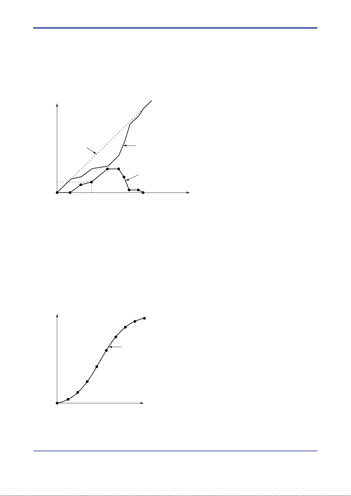
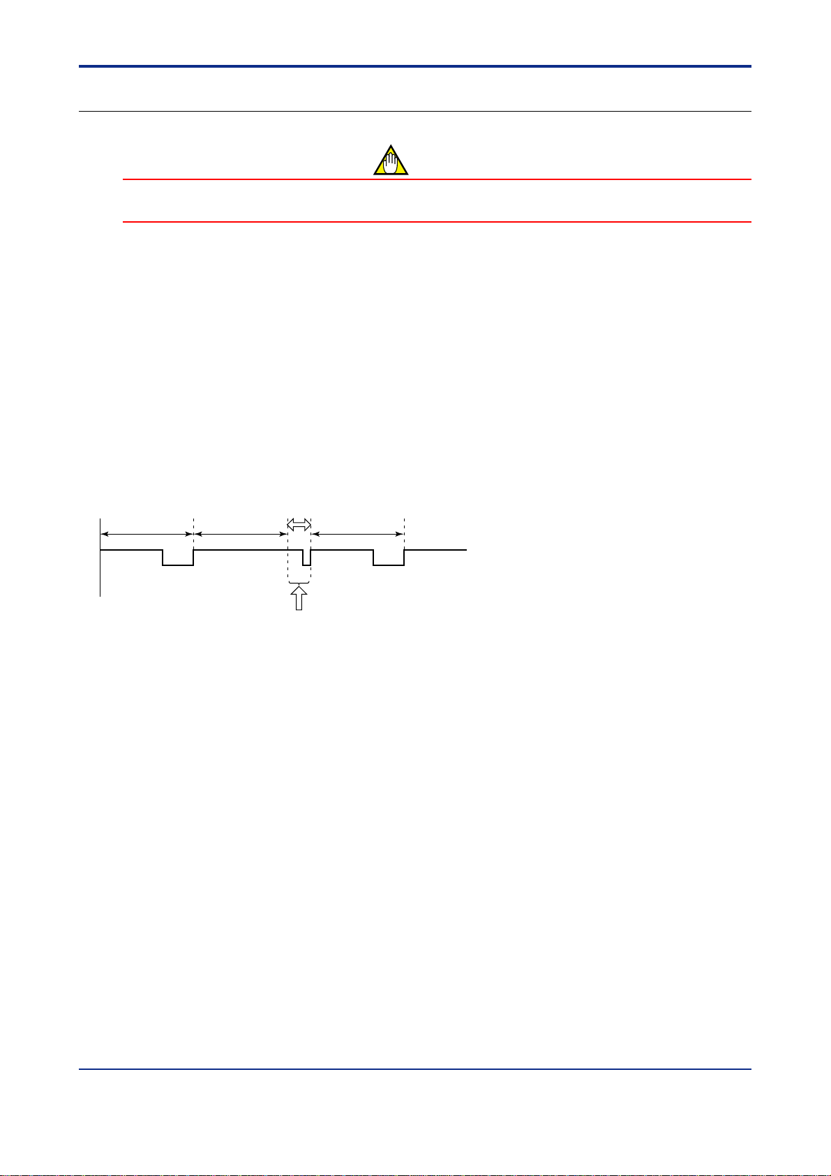
This check is performed by monitoring the sampling error counter.
The counter value shows how many times the controller failed to process its operation at the current PV sampling
period.(The controller increments the counter value by 1 per 10 ms of control period delay when it cannot execute
all the processing within the specified period.)
PV sampling
period
Processing
This chart shows that processing cannot be executed within
the specified sampling period.
In this example, the processing is delayed by 30 ms so the sampling
error counter is incremented by 3.
Fig. 1-1-5 PV Sampling Period
Processing Processing
30ms
If the counter value is not “0,” it means that some of the processing of the controller remains unprocessed.
For this reason, if an exact control is required, set the sampling period so that the counter value will not increase
unless a long time has elapsed.
If the counter value increases in a short period of time, change the sampling period to a larger value.
Y ou can monitor the counter value through the display of setup parameter SMEC (or SMC for UT5) as shown
in the following.
IM 05J01B02-01E 5th Edition : Mar.25,2005-00
Page 21
<Toc> <Ref. 1.1: References Related to PV Input>
Ref. 1-15
Table 1-1-1
PV sampling period Limitations of UT750 functions
50 ms (the fastest) Possible with UT750-00 (single-loop model with no optional specification) when single-loop
control (UT mode = 1) is used and none of the following functions are used.
← This is given as a rough guide (Note).
• SUPER function • Heating/cooling control • PV input computation
• Deviation alarm • Sensor grounding alarm • Self-diagnostic alarm
• FAIL output • SP rate-of-change limiter • Output rate-of-change limiter
100 ms
Possible with single-loop models (UT750-0) when cascade control (UP mode = 4) is not used.
←
Possible with position-proportional models (UT750-1).
This is given as a rough guide (Note).
200 ms (factory-set default) Possible with single-loop models (UT750-0) when cascade control is used.
Possible with single-loop models (UT750-0) and dual-loop models (UT750-5) when
about less than 50 custom computation modules are used. ← “50” is given as a rough guide (Note).
500 ms
When 50 or more custom computation modules are used. ← “50” is given as a rough guide (Note).
Note: • To check that the selected PV sampling period is appropriate, use the setup parameter SMEC described later.
• Set the PV sampling period as 200ms when the “SUPER 2” function is used.
Set the PV sampling period as 500ms when the “SUPER 2” function is used in Cascade control, dual loop control or Temperature and
Humidity control mode.
● The following parameters are used.
• Setup parameters (UP Mode / UT Mode Parameters): SMEC (SMC)
UP750
UP550
UT750
Code
SMEC
Note: Since parameter SMEC is display only, it has no setting range.
UT5
Description Setting range
Default
D-register
No.
Code
320 (Note)
(SMC)
Sampling period
error counter
0 to 30000 (Note)
When the controller is powered on for the first time, the error counter value is 0. The counter value displayed can increase up to 30000
as errors occur. T urning the power of f resets the counter value to 0.
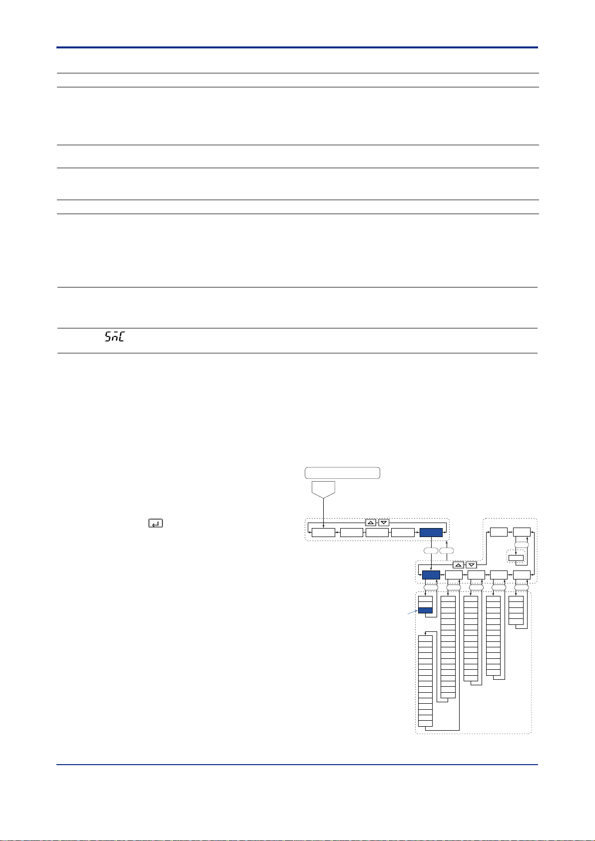
■ Setting the Required Parameters
T o check that the selected PV sampling period is appropriate.
Here we explain how to display the parameter setting display and to change the parameter values. Before carrying
out these operations be sure to refer to the User’s Manuals Initial Settings and Parameter Map of the controller.
The parameter map is very helpful in finding the path to the setting display for a particular parameter.
1: Referring to the User’s Manual above,
display the setup parameter main menu
[UTMD].
Parameter map
Password
(UT750)
Then, display the submenu [MD].
2: Press the
parameter “SMEC”, and check the counter
value.
Note1: “SMC” is the parameter for UT550, UT551 and UT520.
SET/ENT
key 3 times to display the
LOOP1
CONF UTMDLOOP2 CMLP
“SMEC”
TEST
SET DISP
MD IN OUT VALV
SET
UTM
IN1
SMP
UNI1
SMEC
RH1
RL1
SDP1
SH1
SL1
IN3
BSL1
UNI3
RJC1
IN2
RH3
UNI2
RL3
RH2
SDP3
RL2
SH3
SDP2
SL3
SH2
BSL3
SL2
P.UN1
BSL2
P.DP1
RJC2
P.RH1
P.RL1
P.UN2
P.DP2
P.RH2
P.RL2
OT1
OT2
CT1
CT2
CTc1
CTc2
AO1
AO2
AO3
A1H
A1L
A2H
A2L
A3H
A3L
PSL1
BPS1
PRI1
STP1
DLN1
ADR1
RP.T1
PSL2
BPS2
PRI2
STP2
DLN2
ADR2
RP.T2
R485
SETSET
INI
V.RS
V.L
V.H
TR.T
V.MOD
INIT
SET
SETSET
IM 05J01B02-01E 5th Edition : Mar.25,2005-00
Page 22
<T oc> <Ref. 1.1: References Related to PV Input>
<<Ref. 1.1: References Related to PV Input>>
Ref. 1-16
Ref.1.1(6) Correcting the input value from a sensor
CAUTION
The “analog input bias” and “analog input filter” described here are similar to the functions described in “Ref.
1.1 (1) Correcting the PV (1. Using PV filter and PV bias)” of this section.
To use the PV filter and PV bias, operating parameters FL and BS are used. As they are operating parameters, their settings can be changed during operation. Therefore, it is recommended that under normal
circumstances you use FL and BS.
As for “analog input bias” and “analog input filter ,” read the following description and only set them if necessary .
Sensor input value correction is available with UP750, UP550, UT750, UT550, UT551 and UT520.
Analog input bias is used to correct sensor-input characteristics, compensating lead wire errors, and so on.
Normally , the PV biasing (BS) is convenient as mentioned in the CAUTION above, however, use the analog input
bias (A.BS) in cases where a constant correction is required due to sensor deterioration or for other reasons.
Since this biasing is set using a setup parameter , it is suitable for input correction where once the parameter is set,
it will not be changed for a long time.
The analog input filter is used to remove noise from a PV input signal that contains high frequency noise such as
flow rate and pressure signals.
This filter provides a first-order-lag calculation, which can remove more noise the larger the time constant becomes (see the figure below).
However, an excessively large time constant will distort the waveform. (See the figure below)
As mentioned in the CAUTION above, a similar effect can be obtained by using the PV filter (FL).
However, an analog input filter should be used in the cases where a constant level of correction is required, such
as in an environment that contains a lot of noise.
Actual input With a small time constant With an excessively
Fig. 1-1-6 Image of PV Input Correction by Analog Input Filter
large time constant
IM 05J01B02-01E 5th Edition : Mar.25,2005-00
Page 23
<Toc> <Ref. 1.1: References Related to PV Input>
● The following parameters are used.
• Setup parameters (Analog Input Computation Parameters) : A.BS1, A.FL1, etc.
UP750
UP550
UT750
Code
A.BS1
A.FL1
A.BS2
(Note1)
A.FL2
(Note1)
A.BS3
(Note2)
A.FL3
(Note2)
Note 1: These parameters are used for 2-loop type of UP750 or UT750. Not displayed for UP550, UT550, UT551 and UT520.
Note 2: These parameters can be used when the controller has Remote input function.
UT5
Description Setting range
Code
Analog input 1
(BS1)
bias
Analog input 1
(FL1)
no function -100.0% to 100.0% of
filter
Analog input 2
bias
no function OFF or 1 to 120 (sec)
Analog input 2
-100.0% to 100.0% of
input range span
OFF or 1 to 120 (sec)
input range span
filter
(BS3)
(FL3)
Analog input 3
bias
Analog input 3
filter
-100.0% to 100.0% of
input range span
OFF or 1 to 120 (sec)
Default
input range span
(no filter)
input range span
(no filter)
input range span
(no filter)
■ Setting the Required Parameters
T o set the parameters, carry out the following steps.
Ref. 1-17
D-register
No.
10010.0% of
1002OFF
10050.0% of
1006OFF
10090.0% of
1010OFF
Here we explain how to display the parameter setting display and to change the parameter values. Before carrying
out these operations be sure to refer to the User’s Manuals Initial Settings and Parameter Map of the controller.
The parameter map is very helpful in finding the path to the setting display for a particular parameter.
1: Referring to the User’s Manual above,
display the setup parameter main menu
[CMLP].
Then, display the submenu [AIN].
2: Press the
SET/ENT
key once to display the
parameter “A.BS1”. (Note1)
Adjust the parameter value using the /
keys, then press the
SET/ENT
key to
register it.
Note1: “A.BS1” is the parameter for UP750,UP550 and UT750.
“BS1” is the parameter for UT550, UT551 and UT520.
SET/ENT
3 : Press the
key once to display the
parameter “A.FL1”. (Note2)
Set the “Analog input-1 filter” if necessary .
Note2: “A.FL1” is the parameter for UP750,UP550 and UT750.
“FL1” is the parameter for UT550, UT551 and UT520.
Main
menu
Sub menu
Parameter map
Password
OK
“A.BS1”
(UT750)
Operation parameter's
Setting display
DISP
LOOP2LOOP1 CMLP
A.BS1
A.FL1
A.SR1
A.LC1
A.BS2
A.FL2
A.SR2
A.LC2
A.BS3
A.FL3
A.SR3
A.LC3
CONF UTMD
SET DISP
AIN RET TRND LOCK
SETSETSET SET
RET1
DVB1
DVB2
TSC1
TSC2
TTM
/
A/M
MODE
LP1
LP2
PID
USR
PYS1
PYS2
PWD
RTH1
RTL1
RET2
RTH2
RTL2
4: After the above operation, repeat the
following operation if necessary .
• Display the parameter setting display
which you want to set the value.
(ex.“A.BS2”)
• Adjust the parameter value using the
/ keys, then press the
SET/ENT
key
to register it.
TIP
Descriptions of other parameters that belong to submenu AIN, such as parameter A.SR1, are given in “Ref.
1.1 (3) Square-root extraction of PV” of this section. Refer to it as necessary .
IM 05J01B02-01E 5th Edition : Mar.25,2005-00
Page 24

<T oc> <Ref. 1.1: References Related to PV Input>
<<Ref. 1.1: References Related to PV Input>>
Ref. 1-18
Ref.1.1(7) Using PV tracking function (UT only)
The PV tracking function is available with UT750, UT550, UT551. UT520, UT450, and UT420.
PV tracking is used to prevent a sudden change in PV .
Note: As shown below, PV tracking is turned OFF at the time of shipment. T urn it ON if necessary.
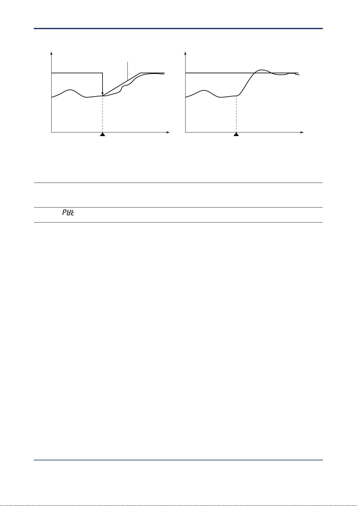
When PV tracking is ON, the controller sets the SP equal to PV temporarily in the event of the following:
• Power-on
• Switching from MAN to AUTO mode
• Switching from STOP to RUN
• Switching the number of setpoint (SP No.)
After SP is equalized to PV, the SP is gradually changed toward the original SP value at a constant rate-of-change
(for ramp rate; see the CAUTION below and the following Fig. 1-1-7).
CAUTION
The SP rate-of-change (ramp rate) is set using parameter UPR and/or DNR, which is set to OFF at the time of
shipment. To use PV tracking, you must set parameter UPR and/or DNR to a desired ramp rate value.
→ See “Ref.4.1(4) Changing SP at a ramp rate when SP is switched” in Ref. 4-1: References Related to Target
Setpoint (SP).
With these parameters OFF, which specifies no ramp rate (ramp rate = 0), PV tracking will not operate.
IM 05J01B02-01E 5th Edition : Mar.25,2005-00
Page 25
<Toc> <Ref. 1.1: References Related to PV Input>
Ref. 1-19
● PV tracking enabled
SP
PV
SP ramp-rate
(UPR or DNR)
MAN AUTO MAN AUTO
mode change mode change
Time Time
● PV tracking disabled
SP
PV
Fig. 1-1-7 PV tracking function
● The following parameters are used.
• Setup parameters (Target Setpoint-related Parameters) : PVT
UP750
UP550
UT750
Code
PVT
Note 1: This parameter is used for loop-2 when the UP/UT mode is set for using loop-2 or secondary loop.
UT5
UT40
Code
(PVT)
Description Setting range
PV tracking selection OFF or ON
Default
OFF
D-register
No.
903(for loop-1)
943(for loop-2)
(Note1)
■ Setting the Required Parameters
T o use the PV tracking function (to turn ON/OFF the PV tracking function), carry out the operation shown below.
Since the operation differs between UT750/UT550/UT551/UT520 and UT450/UT420, instructions will be given
separately in [1] and [2]. Follow either of them according to your controller’s model.
IM 05J01B02-01E 5th Edition : Mar.25,2005-00
Page 26
<T oc> <Ref. 1.1: References Related to PV Input>
Ref. 1-20
[1] UT750, UT550, UT551, UT520
T o set the parameters, carry out the following steps.
Here we explain how to display the parameter setting display and to change the parameter values. Before carrying
out these operations be sure to refer to the User’s Manuals Initial Settings and Parameter Map of the controller.
The parameter map is very helpful in finding the path to the setting display for a particular parameter .
1: Referring to the User’s Manual above,
display the setup parameter main menu
[LOOP1] (Note1).
Then, display the submenu [SP].
Note 1: To set PVT for loop-2, go to the main menu [LOOP2],
then the submenu [SP] and carry out the same procedure.
SET/ENT
2: Press the
key 3 times (Note 2) to
display the parameter “PVT”.
And adjust the parameter value (OFF or
ON) using the
SET/ENT
the
key to register it. (When “ON” is
/ keys, then press
set, PV tracking operate.)
Note 2: The times of key operation may change by the condition
of controller’s setting.
“PVT”
Main
menu
Sub menu
Parameters map
Password
OK
LOOP1
LOOP2 CMLP
SET DISP
SP ALM CTL
RMS
AL1
SPT
AL2
PVT
AL3
TMU
AL4
SPH
HY1
HY2
SPL
HY3
HY4
DY1
DY2
DY3
DY4
AMD
OPR
MOD
AR
ZON
R.MD
R.TM
1.RP
2.RP
3.RP
4.RP
5.RP
6.RP
RHY
RDU
(UT750)
DISP
CONF UTMD
SETSET SET
[2] UT450, UT420
Here we explain how to display the parameter setting display and to change the parameter values. Before carrying
out these operations be sure to refer to the User’s Manuals Initial Settings and Parameter Map of the controller.
The parameter map is very helpful in finding the path to the setting display for a particular parameter .
1: With the operating display shown, press
and hold down the
SET/ENT
key for 3 seconds or
longer to call up [oP.PA].
2: Press the
/ key one time to call up
[STUP].
3: Press the
SET/ENT
key 5 times (Note) to display
the parameter “PVT”. And adjust the
parameter value (OFF or ON) using the
/ keys, then press the
SET/ENT
key to
Parameters map
Operating display
SET
3 sec or more
/
SET
SET
SET
Setup parameters
/
register it. (When “ON” is set, PV tracking
operate.)
Note: The times of key operation may change by the condition
of controller’s setting.
“PVT”
SET
IM 05J01B02-01E 5th Edition : Mar.25,2005-00
Page 27
<Toc> <Ref. 1.1: References Related to PV Input>
Ref. 1-21
<<Ref. 1.1: References Related to PV Input>>
Ref.1.1(8) PV input range adjustment (When the UT/UP mode No. is 6, 7 or 12 only)
Parameters RH1 to RL3 are used to set the range used for control within the instrument range.
Parameters P.RH1 to P.RL2 (PV range) are used to set the PV ranges used for the controller’s internal computation when the controller performs loop control with PV switching or loop control with PV auto-selector which
receives two inputs of different measurement ranges (see Fig. 1-1-8). The parameters are also used to set the PV
range for relative humidity data obtained from dry- and wet- bulb calculations in temperature and humidity control.
The decimal point position of the PV range can be set with parameters P.DP1 and P.DP2.
P.RL1 P.RH1
RL2 or 3
RL1 RH1
Range of analog input 1
0 300 500 1000C
PV range
Range of analog input 2 or 3
Fig. 1-1-8 PV Range for a Control Having More than One Input
Dry bulb (Input 1)
-50 to 100C
Dry- and wet-bulb
PV1
-50 to 100C
Wet bulb (Input 2)
-50 to 100C
calculation
PV range convention
30.0 to 100.0%
<Example>
Sets
• _ _ _ _. _ for P.DP2,
• 100.0 for P.RH2, and
• 30.0 for P.RL2.
PV2
Fig. 1-1-9 PV Range for T emperature and Humidity Control
• Setup parameters (Input-related Parameters): P.UNn, P.RLn, etc
UP750
UP550
UT750
Code
P.UNn
(Note1)
P.DPn
P.RHn
UT55
UT520
Code
(P.Un)
(P.D1)
(P.H1)
Description
n
n
n
PVn Unit C : Degree Celsius
PVn decimal
Maximum value
of PVn range
Setting range
% : Percent
C : Degree Celsius
F : Fahrenheit
– : No unit
0 to 4 (Note2)
-19999 to 30000
(Note3)
RH2 or 3
Default
–
Maximum value
of PVn range
or scale
D-register No.
1230 (for loop-1)
1234 (for loop-2)
1231 (for loop-1)
1235 (for loop-2)
1232 (for loop-1)
1236 (for loop-2)
P.RLn
Note1: The “n” in the table is 1 or 2. The number 1 or 2 indicates the number of loop.
Note2: The number 0 to 4 of setting range means that: 0: no decimal point, 1: one digit below decimal point, 2: two digits below
decimal point, 3: three digits below decimal point, 4: four digits below decimal point
Note3: Under normal operation, keep the value of these parameters between the maximum and minimum values of the PV range.
n
(P.L1)
• When UP750,UP550 or UT750, P .RL1< P.RH1, where (P.H1-P.RL1)30000
• When UT550, UT551 or UT520, P .L1< P.H1, where (P.H1-P.RL1)30000
Minimum value
of PVn range
-19999 to 30000
(Note3)
Minimum value
of PVn range
or scale
IM 05J01B02-01E 5th Edition : Mar.25,2005-00
1233 (for loop-1)
1237 (for loop-2)
Page 28

<T oc> <Ref. 1.2: References Related to Remote Input>
Ref.1.2: References Related to Remote Input
Ref. 1-22
IMPORTANT
UP750 UP550 UP35 UT750 UT5 UT40 UT3
None None None UT750-1 UT450-1
Note: Some of the functions below are not available on certain models. For more information, see those sections.
: Applicable models of this section
UT55-1
UT55-2
UT55-4
UT551-B
UT551-D
UT52-7
UT52-8
UT450-2
UT450-4
UT420-7
UT420-8
None
This section contains reference information on the following aspects of remote input. Refer to this information and
change parameters only if necessary .
(1) Setting remote input units, range and scaling
(2) Using square root extraction during remote input
(3) Using remote setpoint filtering and ratio bias computing
(4) Tracking target setpoint when switching from remote to local control
IM 05J01B02-01E 5th Edition : Mar.25,2005-00
Page 29
<Toc> <Ref. 1.2: References Related to Remote Input>
<<Ref.1.2: Reference Related to Remote Input>>
Ref.1.2(1) Setting remote input units, range and scaling
T o use these remote input functions, the controller must have auxiliary analog input capabilities.
Auxiliary analog input is indicated as “input-3” in the parameter table below.
● The following parameters are used.
• Setup parameters (Input-related Parameters) : IN3, UN3, RH3, RL3, SDP3, SH3, SL3
UT750
Code
UT5
Code
IN3
(IN3)
UNI3
(UN3)
RH3
(RH3)
RL3
(RL3)
SDP3
(DP3)
SH3
(SH3)
SL3
(SL3)
Note 1: UT450/UT420 do not have these parameters.
For UT450/UT420, use “DPC”, “RSH” and “RSL” parameters for the settings.
For UT551, revers range can be set.
UT40
Code
(RSP)
–
–
–
–
(RSH)
(RSL)
Description Setting range
Remote Input type
(Input-3 type)
Remote Input unit
(Note 1)
Maximum value of remote
input range (Note 1)
Minimum value of remote
input range (Note 1)
Remote input decimal
point position
(Note 1)
Max. value of
remote input scale
Min. value of
remote input scale
0.4 to 2V (40)
1 to 5V (41)
0 to 2V (50)
0 to 10V (51)
%
C
– (no unit)
F
Within the PV input range
0: 99999 (no decimal point)
1: 9999.9
2: 999.99
3: 99.999
4: 9.9999
-19999 to 30000
However, SL1<SH,
SH1-SL130000
Default
UT5: 41
UT40 : 41
%
5.000
1.000
1
Maximum value
of remote
input range
Minimum value
of remote
input range
Ref. 1-23
D-register
No.
1221UT750 : 1 to 5V
1222
1224
1225
1226
1227
1228
IM 05J01B02-01E 5th Edition : Mar.25,2005-00
Page 30
<T oc> <Ref. 1.2: References Related to Remote Input>
Ref. 1-24
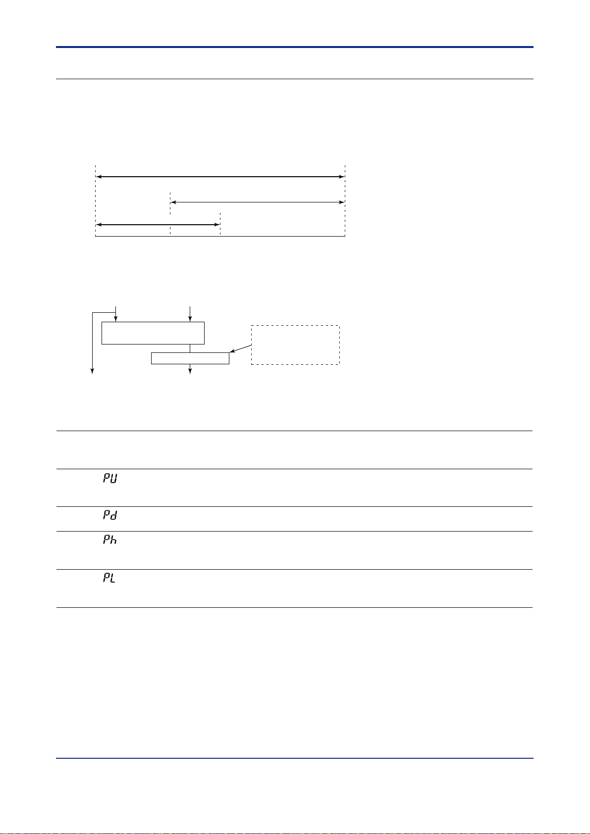
Setting Example (1) For UT750 and UT5
The example below shows signal type, units, range and scaling setpoints used for remote input with the UT750,
UT550, UT551 and UT520.
For example, with analog input-3 (IN3) = 41, the remote input range is 1.000 to 5.000 for standard signals (1 to 5
V).
Here, for an input range of 2 to 4 V , set as follows.
Maximum value of analog input-3 range (RH3) = 4,000 (Ref.: “3,500” means 3.5 V.)
Minimum value of analog input-3 range (RL3) = 2,000
1V 2V 5V4V
Input range of
analog input-3
Remote input range
EU (100)%EU (0)%
4.000 (RH3)2.000 (RL3)
Fig. 1-2-1
In the above example, remote input range was set to 2 to 4 V . To change the input voltage signal to the physical
unit of the actual controlled condition (hereinafter, “ scaling”), see the Setting Scaling Procedure.
Setting Scaling Procedure
(1) For UT750 and UT5
The following procedure shows how to change setpoints from the factory-set defaults.
1V 2V 5V4V
EU (0) %
Input range of
analog input-3
(IN=41)
EU (100) %
Step1
Minimum value of PV
input range or PV input
scale (i.e.:-270.0)(SL3)
10.00 (SL3)
Remote input range
Physical quantity range
Remote input range
after scaling
4.000V (RH3)2.000V (RL3)
For UT551, reverse range can be set.
RL3=4.000V, RH3=2.000V
Maximum value of PV
input range or PV input
scale (i.e.:1370.0)(SH3)
50.00 (SH3)
Fig. 1-2-2
Step1: This example shows a remote input range of 1.000 to 5.000 for standard signals
(1 to 5 V) for an analog input -3 type (IN3) = 41.
Step2: In this example, the remote input range is set as 2.000 to 4.000V using the parameters
RL3 and RH3.
Step3: With the UT750/UT5 the same units and decimal point position set for the PV
input range are used for the remote input range. For this reason, if the PV input range
is set to a thermocouple type K ( -270.0 to 1370.0 C) the initial value of SL3 is set
to “-270.0” and that of SH3 is set to “1370.0” .
Step4: Change the initial settings of SDP3,SL3 and SH3 to the actual values for the remote
Input range. In this example, the SDP3 is set to “2” and SL3 is set to “10.00” and the
SH3 is set to “50.00”.
Step2
Step3
Step4
IM 05J01B02-01E 5th Edition : Mar.25,2005-00
Page 31

<Toc> <Ref. 1.2: References Related to Remote Input>
Ref. 1-25
Setting Example (2) For UT40
The example below shows signal type, units, range and scaling setpoints used for remote input with the UT40.
For example, with remote input type (RSP) = 41, the remote input range is 1.000 to 5.000 for standard signals (1 to
5 V).
Note: Unlike the UT750 and UT5, the UT40 does not have RH3 and RL3 parameters, therefore input signal range cannot be changed.
T o change the input voltage signal (1 to 5 V in this case) to the physical unit of the actual controlled condition (hereinafter, “scaling”),
see the Setting Scaling Procedure.
Setting Scaling Procedure
(2) For UT40
The following procedure shows how to change setpoints from the factory-set defaults.
1V 2V 5V4V
EU (0)%
Minimum value of PV
input range or PV input
scale (i.e.: -270.0)(
10.0 (R.SL)
R.SL)
Input range of
analog input-3
Remote input range
after scaling
(IN = 41)
EU (100)%
Maximum value of PV
input range or PV input
scale (i.e.: 1370.0)
50.0 (R.SH)
(R.SH)
Fig. 1-2-3
Step1: This example shows a remote input range of 1.000 to 5.000 for standard signals
(1 to 5 V) for a remote input type (RSP) = 41.
Step2: With the UT450/UT420, the same units and decimal point position set for the PV input
range are used for the remote input range. For this reason, if the PV input range is
set to a thermocouple type K ( -270.0 to 1370.0 C) the initial value of R.SL is set to
“-270.0” and that of R.SH is set to “1370.0”.
Step3: Change the initial settings of R.SL and R.SH to the actual values for the remote input
Range. In this example, the R.SL is set to “10.0” and the R.SH is set to “50.0”.
Step 1
Step 2
Step 3
IM 05J01B02-01E 5th Edition : Mar.25,2005-00
Page 32

<T oc> <Ref. 1.2: References Related to Remote Input>
■ Setting the Required Parameters
Carry out the operation shown below.
(UT5’s parameter setting way is shown in the following example. )
Here we explain how to display the parameter setting display and to change the parameter values. Before
carrying out these operations be sure to refer to the User’s Manuals Initial Settings and Parameter Map of the
controller.
The parameter map is very helpful in finding the path to the setting display for a particular parameter .
Ref. 1-26
1: Referring to the User’s Manual above,
display the setup parameter main menu
[UTMD].
Then, display the submenu [IN].
2 : Press the
SET/ENT
key time and again to display
the parameter “IN3”.
Adjust the parameter value using the
/ keys, then press the
SET/ENT
key to
register it.
For example, when you want to select “1
to 5V ” input range, adjust the parameter
value to
“41” and register it by pressing the
3 : Press the
SET/ENT
key once to display the
SET/ENT
parameter “UN3”.
Set the “Remote Input Unit” if necessary .
4: After the above operation, repeat the
following operation for the parameters
“RH3”, “RL3”, “DP3”, “SH3” and “SL3” if
necessary .
• Display the parameter setting display
key.
UT550/UT520 Parameter map
Pass word
Main menu
Sub menu
OK
LOOP1
Operating parameters
+
“IN3”
UTMDLOOP2 CONF
SET
+
MD IN OUT VALV
SET
UTM
IN1
UNI1
RH1
RL1
DP1
SH1
SL1
BO1
RJC
IN3
UN3
RH3
RL3
DP3
SH3
SL3
BO3
P.D2
P.H2
P.L2
OT1
OT2
CTc
AO1
AO2
AO3
A1H
A1L
A2H
A2L
A3H
A3L
CT
SMP
SMC
which you want to set the value.
(ie.“RH3”)
• Adjust the parameter value using
the
the
/ keys, then press
SET/ENT
key to
register it.
This completes the setting operation. If other settings are unnecessary , return to the operating display.
PSL
BPS
PRI
STP
DLN
ADR
RP.T
TEST
R485
SETSET
V.AT
V.RS
V.L
V.H
TR.T
V.MD
INIT
SET
INI
SETSET
IM 05J01B02-01E 5th Edition : Mar.25,2005-00
Page 33

<Toc> <Ref. 1.2: References Related to Remote Input>
Ref. 1-27
<<Ref.1.2: Reference Related to Remote Input>>
Ref.1.2(2) Using square root extraction during remote input
Square-root extraction is available with UT750 and UT5 controllers that have auxiliary analog input capabilities. (It cannot be used with the UT40.) Square-root extraction can be used with remote input as shown in the
flowchart below. It is also possible to set the square-root low signal cut of f.
Setpoints 1 - 8
Local Remote
Target setpoint
Remote input
(Auxiliary analog input)
Square-root extraction
Remote setpoint
filtering
Ratio bias
computation
Remote input selection
Remote/Local selection
Target setpoint
for ramp setting
Controller CPU
RS485
PV
Fig. 1-2-4 Processing for remote setpoint input
● The following parameters are used.
Change parameters as explained in the User’s Manuals Initial Settings and Parameter Map.
• Setup parameters (Analog Input Computation Parameters) : A.SR3, A.LC3
UT750
Code
A.SR3
A.LC3
UT5
Code
(SR3)
(LC3)
Description Setting range
Analog input-3
OFF, ON 1011OFF
square-root computation
Analog input-3
low signal cut off
of PV input range
Default
1.0% 10120.0 to 5.0%
D-register
No.
Out put
Low signal cut off point
0.0 to 5.0%
Fig. 1-2-5 Square-root Extraction
Input
IM 05J01B02-01E 5th Edition : Mar.25,2005-00
Page 34

<T oc> <Ref. 1.2: References Related to Remote Input>
Ref. 1-28
<<Ref.1.2: Reference Related to Remote Input>>
Ref.1.2(3) Using remote setpoint filtering and ratio bias computing
The function described below is available with UT750,UT5 and UT40 controllers that have auxiliary analog
input (Remote input) capabilities.
Remote setpoint filtering and Ratio bias computation can be used with remote input as shown in the flowchart
below.
Setpoints 1 - 8
Local Remote
Target setpoint
Remote input
(Auxiliary analog input)
Square-root extraction
Remote setpoint
filtering
Ratio bias
computation
Remote input selection
Remote/Local selection
Target setpoint
for ramp setting
Controller CPU
RS485
PV
Fig. 1-2-6
■ Remote setpoint filtering
Remote setpoint filtering performs first-order-lag computation for the remote setpoint value (signal) transmitted
from the external equipment.
The function of Remote setpoint filtering is same as that of PV input filter.
Refer the “ Ref. 1.1 (1) Correcting the PV (1.Using PV input filter and PV input bias)”.
● The following parameters are used.
Change parameters as explained in the User’s Manuals Initial Settings and Parameter Map.
• Operating parameters (Operation-related Parameters) : RFL
UT750
Code
RFL
Note: With UT750-1, UT55-1, UT55-2, UT55-4, UT551-B, UT551-D, UT520-07, UT520-08, this parameter is displayed only
UT5
UT40
Description Setting range
Code
Remote input filter
OFF, 1 to 120sec loop-1: 249
(RFL)
for loop-1.
(However the function of this parameter is used at loop-1 and loop-2 in common.)
(With UT40-, loop-1 only .)
Default
OFF
D-register
No.
loop-2: 279
IM 05J01B02-01E 5th Edition : Mar.25,2005-00
Page 35

<Toc> <Ref. 1.2: References Related to Remote Input>
Ref. 1-29
■ Ratio bias computing
Ratio bias computing performs ratio computation and bias addition for remote setpoints. This enables load distribution by zone, air-heat ratio control, 2-flow ratio control, etc.
This function acts on setpoints of substations used in coordinated operation.
Computation: SP = Remote setpoint input Ratio Remote input bias
● The following parameters are used.
Change parameters as explained in the User’s Manuals Initial Settings and Parameter Map.
• Operating parameters (Operation-related Parameters) : RT , RBS
UT750
Code
RT
RBS
UT5
UT40
Code
(RT)
(RBS)
Description Setting range
Ratio setting
Remote input bias -100.0 to100.0% of PV
0.001 to 9.999 loop-1 : 247
input range span
Default
1.000
0.0% of PV
input range span
D-register
No.
loop-2 : 277
loop-1 : 248
loop-2 : 278
IM 05J01B02-01E 5th Edition : Mar.25,2005-00
Page 36

<T oc> <Ref. 1.2: References Related to Remote Input>
Ref. 1-30
<<Ref.1.2: Reference Related to Remote Input>>
Ref.1.2(4) Tracking target setpoint when switching from remote to local control
Setpoint can be tracked with UT750, UT5 and UT40 controllers that have auxiliary analog input capabilities.
This function equalizes the local setpoint to the remote setpoint when switching from remote to local control. This
prevents any sudden change in setpoint when control is switched from remote to local.
Setpoint tracking functions as follows.
Setpoint tracking ON
Regardless of any preset local setpoints, the remote
setpoint is used as the local setpoint when control is
switched from remote to local. To use the preset
local setpoint, punch in the setpoint from the keys.
Preset local
setpoint
Remote
setpoint
Control switched from
remote to local here.
PV
Time
Setpoint tracking OFF
When control is switched from remote to local, the
preset local setpoint is used in operation.
Preset local
setpoint
Remote
setpoint
Control switched from
remote to local here.
Fig. 1-2-7 Setpoint tracking
● The following parameters are used.
Change parameters as explained in the User’s Manuals Initial Settings and Parameter Map.
• Setup parameters (Target Setpoint-related Parameters) : SPT
UT750
Code
SPT
Note: This parameter can be displayed with UT750,UT5 and UT40 controllers that have auxiliary analog input capabilities.
UT5
UT40
Code
(SPT)
Description Setting range
SP tracking selection
(Note)
OFF, ON loop-1 : 902
Default
ON
PV
Time
D-register
No.
loop-2 : 942
IM 05J01B02-01E 5th Edition : Mar.25,2005-00
Page 37

<Toc> <Ref. 2.1: References Related to Control Output>
Ref.2.1: References Related to Control Output
Ref. 2-1
IMPORTANT
UP750 UP550 UP35 UT750 UT5 UT40 UT3
UP750- UT750-UP550- UP35- UT5- UT40- UT3-
Note: Some of the functions discussed below may be limited to models with a specific suffix and/or option code. Each section will expressly
refer to this limitative condition where it applies.
This section contains reference information on the following advanced controller operations related to control
output. Refer to this information and set parameters (or change their settings) only if necessary .
: Applicable models of this section
(1) Switching between Direct and Reverse Actions
(2) Selecting PID Control Mode According to the Operating Condition
- Determining whether or not a change in the target setpoint involves control output
bump
(3) Using Control Output Limiter
(4) Using Anti-reset Windup (Over-integration Prevention) Function
(5) Using “Super” (Overshoot Prevention) Function
(6) Using “Super2” (Hunting Prevention) Function
(7) Using Split-signal Computation/Output Function
(8) Setting Preset Output Values
(9) Placing Control Output in Tracking Mode (for Cascade Primary-loop Control or Loop
Control for Backup)
(10) Using Shutdown Function
IM 05J01B02-01E 5th Edition : Mar.25,2005-00
Page 38

<T oc> <Ref. 2.1: References Related to Control Output>
Ref. 2-2
<<Ref. 2.1: References Related to Control Output>>
Ref.2.1(1) Switching between Direct and Reverse Actions
Switching between direct and reverse actions is possible with all models* in the UP and UT series of controllers.
(*UP750, UP550, UP35, UT750, UT5, UT40 and UT3)
The terms direct action and reverse action define the directions in which the control output changes to increase or
decrease its value according to whether the deviation of a measured value (PV) from the target setpoint (SP) is
positive or negative. The controller increases or decreases its control output value in the predetermined mode,
either direct action or reverse action, in conjunction with the deviation of the current PV value from the SP value.
Note that there are no direct/reverse action options for heating/cooling control.
Y ou can switch between direct and reverse actions even when the controller is in operation. To switch, use the
parameter appropriate for your controller model, as noted below.
•“n.DR” operating parameter for the UP750, UP550, UT750, UT5 and UT40
• DR operating parameter for the UP35 and UT3
In the reverse action mode (factory-set default), the control output value decreases if the PV value is greater than
the SP value. Inversely , it increases if the PV value is smaller than the SP value (see Fig. 2-1-1 below).
Reverse Action Direct Action
Condition
ON/OFF
output status
PV>SP
OFF
PV<SP
ON
PV>SP
ON
PV<SP
OFF
Current output
Time proportional
output
Direction of
change in
control output
Decreases.
The ON-state time
decreases.
Reverse Action
20mA
(Increase)
↑
Output
value
↓
(Decrease)
4mA PV value
Minimum
(PV value is smaller)
Increases.
The ON-state time
increases.
SP value
Maximum
(PV value is greater)
Fig. 2-1-1 Switching between Direct and Reverse Actions
Increases.
The ON-state time
increases.
Direct Action
20mA
(Increase)
↑
Output
value
↓
(Decrease)
4mA
Minimum
(PV value is smaller)
Decreases.
The ON-state time
decreases.
SP value
PV value
Maximum
(PV value is greater)
IM 05J01B02-01E 5th Edition : Mar.25,2005-00
Page 39

<Toc> <Ref. 2.1: References Related to Control Output>
● The following parameters are used.
Change parameters as explained in the User's Manuals Initial Settings and Parameter Map.
• Operating parameters (PID-related Parameters) : n.DR
UP750
UP550
UT750
Code
(Note1)
n.DR
Note1: “n” = 1 to 8. The number indicates the number of PID group.
Note2: This parameter cannot be displayed when heating/cooling control mode.
Note3: The D-register numbers are shown in the Table 2-1-1. ( except for UP35, UT3)
UT5
UT40
Code
(Note1)
n.
(n.DR)
UP35
UT3
Code
(DR)
Description
Direct / reverse
action switching
(Note2)
Setting range Default D-register No.
• When UP750, UP550, UT750
REVERSE: Reverse action
DIRECT: Direct action
• When UT5, UT40
RVS: Reverse action
DIR : Direct action
• When UT3/UP35
0 : Reverse action
1 : Direct action
Reverse action
• UP750, UP550, UT750 :
REVERSE
• UT5/UT40 : RVS
• UT3/UP35 : 0
T able 2-1-1 1st=for loop-1 2nd=for loop-2 (UT40 has no loop-2)
Ref. 2-3
• 257
(When UP35
or UT3)
(Note3)
n.DR
313
1st
n= 1
2nd
513
1st
338
n=2
2nd
538
1st
363
n=3
2nd
563
1st
388
n=4
2nd
588
1st
413
n=5
n=6
2nd
1st 2nd
438 638 463 663 488 688
613
n=7
1st 2nd
n=8
1st 2nd
IM 05J01B02-01E 5th Edition : Mar.25,2005-00
Page 40

<T oc> <Ref. 2.1: References Related to Control Output>
Ref. 2-4
<<Ref. 2.1: References Related to Control Output>>
Ref.2.1(2) Selecting PID Control Mode According to the Operating Condition
- Determining whether or not a change in the target setpoint involves control
output bump
With UP and UT series controllers, you can select between two types of PID control modes. These control modes
are referred to as the standard PID control mode and fixed-point control mode.
For each of these PID control modes, select either the PV derivative type PID control method or deviation derivative type PID control method to carry out control according to the operating condition (mode). You can also select
from the Yes/No options for a control output bump at the moment of change in the SP value. (See Table 2-1-2 or
2-1-3 depending on your controller model.)
Note that there is a slight difference in this information between the UP750, UP550, UT750, UT5 and UT40
group of controllers and the UP35 and UT3 group controllers.
This section discusses the former group first and then the latter group. See either reference topic according to
your controller model.
[1] Control Mode Selection when the Model Is UP750, UP550, UT750, UT5 or UT40
To select the PID control mode, use one of the setup parameters explained below .
To set/change the parameter , see the Initial Settings or Parameters user’s manual of the model in question.
■ Setup Parameters for UP750, UP550 and UT750
• Setup parameters (Control Action-related Parameters):MOD1, MOD2 and MOD
UP750
UP550
Code
MOD1 MOD
MOD2
(Note2)
Note1: For the UT750, the MOD setup parameter applies to both the loop-1 and loop-2 PID control modes. More specifically, the MOD setup
Note2: The MOD2 setup parameter for the loop-2 PID control mode of the UP750 or UP550 is only shown when the UP mode is cascade
UT750
Description Setting Range
Code
Loop-1 PID
(Note1)
MOD
(Note1)
parameter belonging to the LOOP2 setup parameter main menu is used for the loop-2 PID control mode of the UT750. In addition, the
setup parameter has the same name, MOD, as the one that belongs to the LOOP1 menu (though their D-register numbers differ , as
shown in the table above).
The MOD setup parameter for loop 2 is only shown when the UT mode is cascade control, dual-loop control, temperature/humidity
control or cascade control with two universal inputs.
control, dual-loop control, temperature/humidity control or cascade control with two universal inputs.
control mode
Loop-2 PID
control mode
0: Standard PID control mode
1: Fixed-point control mode
0: Standard PID control mode
1: Fixed-point control mode
Default D-register No.
9270
9670
■ Setup Parameters for UT5 and UT40
• Setup parameters (Control Action-related Parameters):MOD
UT5
UT40
Code
(MOD)
Note: For the UT5 and UT40, there is no parameter for loop-2.
Description Setting Range
PID control mode
0: Standard PID control mode
1: Fixed-point control mode
Default D-register No.
9270
IM 05J01B02-01E 5th Edition : Mar.25,2005-00
Page 41

<Toc> <Ref. 2.1: References Related to Control Output>
The relationship between the control mode and operating condition of the UP750, UP550, UT750, UT5 and
UT40 is as shown in Table 2-1-2 below.
Refer to the information under “Control Method” and “Description of Control Action,”
to set the type of PID control
mode appropriate for the operating condition (mode) you will use, using the setup parameter discussed earlier.
T able 2-1-2 Control Mode vs. Operating Condition Relationship for UP750, UP550, UT750, UT5 and UT40
Ref. 2-5
Type of PID
Control Mode
Standard PID
control mode
Factory-set values
For the UP50,
the mode is
defined by setting
MODn =
0 (n = 1 or 2).
For the UT750,
the mode is
defined by setting
MOD = 0.
Fixed-point
control mode
Control Method Description of Control Action
PV derivative type
PID control
Control output bump is
allowed during change
in SP value.
Deviation derivative
type PID control
PV derivative type
PID control
Control output bump is
not allowed during
change in SP value.
The PV derivative type PID control mode is adopted so that
the controller can reach the new SP value without delay when
the current SP value is changed.
In this control mode, the controller immediately outputs the
value of the proportional term P which is proportional to the
deviation resulting from a change in the SP value.
The controller thus attempts to reach the new SP value as
soon as possible.
SP
The deviation derivative type PID control mode is adopted in
order to improve the follow-up capability of UP series program
controllers for marginal variations in the SP value of a program
pattern.
By allowing the derivative term D to positively act upon
variations resulting from a marginal change in the program
pattern, the controller keeps track of the pattern without delay.
SP
PV
Use this control method in order to protect the PV value from
any disorder that may result when the control output (MV)
reacts over-sensitively against a change in the SP value during
continuous fixed-point control.
If the PV derivative type PID control mode is used with the
permitted control output bump, the MV value does not change
suddenly during a change in the SP value. The controller uses
the integral term I only and gradually eliminates the deviation
that has occurred.
PV
Operating Condition
(Mode)
• For UT series (Note1)
Local mode operation
• For UP series (Note2)
Local mode (Note3),
hold mode or soak
mode operation
MV
• For UT series
Remote mode or
cascade mode
operation
• For UP series
Program mode
operation (except for
hold or soak mode)
MV
• For UT series (Note1)
Local mode operation
• For UP series (Note2)
Local mode (Note3),
hold mode or soak
mode operation
Factory-set values
For the UP50,
the mode is
defined by
setting as
MODn = 1
(n = 1 or 2).
For the UT750,
the mode is
defined by setting
as MOD = 1.
Note1: In the table above, the UT series refers to the UT750, UT5, UT40 and UT3.
Note2: In the table above, the UP series refers to the UP750, UP550 and UP35.
Note3: The local mode of the UP series refers to the operating mode in which the SP value is kept constant.
PV derivative type
PID control
Control output bump is
allowed during
change in SP value.
SP
PV
Use this control method when using the controller for the
secondary loop of cascade control. In this method, the control
output never reacts over-sensitively against a change in the
primary-loop output. Rather, it delivers stable control output.
SP
MV
MV
PV
IM 05J01B02-01E 5th Edition : Mar.25,2005-00
• For UT series
Remote mode or
cascade mode
operation
• For UP series
Program mode
operation (except for
hold or soak mode)
Page 42

<T oc> <Ref. 2.1: References Related to Control Output>
[2] Control Mode Selection when the Model Is UP35, UT35 or UT32
To select the PID control mode, use one of the setup parameters explained below .
To set/change the parameter , see the Initial Settings or Parameters user’s manual of the model in question.
• Setup parameters (Control Action-related Parameters):C.MD
UP35
UT3
Code
(C.MD)
Description Setting Range
PID control mode
0: Standard PID control mode
1: Fixed-point control mode
Default D-register No.
9270
The relationship between the control mode and operating condition of the UP35, UT35 and UT32 is as
shown in Table 2-1-3 below.
Refer to the information under “Control Method” and “Description of Control Action,”
to set the type of PID control
mode appropriate for the operating condition (mode) you will use, using the setup parameter discussed earlier.
Table 2-1-3 Control Mode vs. Operating Condition Relationship for UP35, UT35 and UT32 (1/2)
Ref. 2-6
Type of PID
Control Mode
Standard PID
control mode
Factory-set values
C.MD = 0
Control Method Description of Control Action
PV derivative type
PID control
Control output bump is
allowed during change
in SP value.
Deviation derivative
type PID control
The PV derivative type PID control mode is adopted so that
the controller can reach the new SP value without delay when
the current SP value is changed.
In this control mode, the controller immediately outputs the
value of the proportional term P which is proportional to the
deviation resulting from a change in the SP value.
The controller thus attempts to reach the new SP value as
soon as possible.
SP
The deviation derivative type PID control mode is adopted in
order to improve the follow-up capability of UP series program
controllers for marginal variations in the SP value of a program
pattern.
By allowing the derivative term D to positively act upon
variations resulting from a marginal change in the program
pattern, the controller keeps track of the pattern without delay.
PV
Operating Condition
(Mode)
• For UT3
When “SP number” is
set to 1, 2, 3 or 4.
• For UP35
Hold mode or soak
mode operation
MV
• For UT3
When “SP number” is
set to 0. (When using
communication
function)
• For UP35
Program mode
operation (except for
hold or soak mode)
SP
PV
MV
IM 05J01B02-01E 5th Edition : Mar.25,2005-00
Page 43

<Toc> <Ref. 2.1: References Related to Control Output>
T able 2-1-3 Control Mode vs. Operating Condition Relationship for UP35, UT35 and UT32 (2/2)
Ref. 2-7
Type of PID
Control Mode
Fixed-point
control mode
C.MD = 1
Control Method Description of Control Action
PV derivative type
PID control
Control output bump is
not allowed during
change in SP value.
PV derivative type
PID control
Control output bump is
allowed during
change in SP value.
Use this control method in order to protect the PV value from
any disorder that may result when the control output (MV)
reacts over-sensitively against a change in the SP value during
continuous fixed-point control.
If the PV derivative type PID control mode is used with the
permitted control output bump, the MV value does not change
suddenly during a change in the SP value. The controller uses
the integral term I only and gradually eliminates the deviation
that has occurred.
SP
Use this control method when using the controller for the
secondary loop of cascade control. In this method, the control
output never reacts over-sensitively against a change in the
primary-loop output. Rather, it delivers stable control output.
SP
PV
PV
Operating Condition
(Mode)
• For UT3
When “SP number” is
set to 1, 2, 3 or 4.
• For UP35
Hold mode or soak
mode operation
MV
• For UT3
When “SP number” is
set to 0. (When using
communication
function)
• For UP35
Program mode
operation (except for
hold or soak mode)
MV
IM 05J01B02-01E 5th Edition : Mar.25,2005-00
Page 44

<T oc> <Ref. 2.1: References Related to Control Output>
<<Ref.2.1: References Related to Control output>>
Ref.2.1(3) Using Control Output Limiter
This function can be used with UP750, UP550, UT750, UT5, UT40 and UT3 .
For the function, the parameters “n.OH” and “n.OL” are used.
These parameters limit the control output, regardless of the operation mode.
UT750, UT5, UT40, UP750 and UP550 can set up to eight sets of “n.OH” and “n.OL” . (n=1 to 8)
CAUTION
The preset output value output when the controller operation stopped, will not be limited even when the
“n.OH” and “n.OL” limits of output have been set.
(%)
105.0
Output high limit
Range of output
signal variation
Ref. 2-8
Output low limit
Signal output from the terminal
0
-5.0
Original variable range
Note: Setting range : -5.0% n.OL n.OH 105.0%
Variable
range
n.OHn.OL
105.0 (%)
Fig. 2-1-2
● The following parameters are used.
Change parameters as explained in the User's Manuals Initial Settings and Parameter Map.
• Operating parameters (PID-related Parameters) : n.OH, n.OL
UP750
UP550
UT750
Code
n.OH
(Note1)
n.OL
(Note1)
Note1: “n”=1 to 8, means the number of PID group.
Note2: Not displayed in ON/OFF control mode.
UT5
UT40
Code
n.
n.
(n.OH)
n.
(n.OL)
UP35
UT3
Code
(OH)
(OL)
Description Setting range
Output high limit
Heating-side output high
limit (in heating/cooling
control) (Note2)
Output low limit
Cooling-side output high
limit (in heating/cooling
control) (Note2)
-5.0 to 105%
(OLOH),
0.0 to 100.0%
(in heating/cooling
control)
-5.0 to 105%
(OLOH),
0.0 to 100.0%
(in heating/cooling
control)
Default D-register No.
100.0%
0.0%
100.0%
(in heating/cooling
control)
• 254
(When UP35, UT3)
• See Table 2-1-4
(except for UP35, UT3)
• 255
(When UP35, UT3)
• See Table 2-1-4
(except for UP35, UT3)
Table 2-1-4 1st : for loop-1 2nd : for loop-2 (UT40 has no loop-2)
n.OH
n.OL
1st
309
310
n=1
2nd
509
510
1st
334
335
n=2
2nd
534
535
1st
359
360
n=3
2nd
559
560
1st
384
385
n=4
2nd
584
585
1st
409
410
n=5
2nd
609
610
n=6
1st 2nd
434
435
n=7
1st 2nd
634
459
659
635
460
660
IM 05J01B02-01E 5th Edition : Mar.25,2005-00
n=8
1st 2nd
484
485
684
685
Page 45

<Toc> <Ref. 2.1: References Related to Control Output>
<<Ref.2.1: References Related to Control output>>
Ref.2.1(4) Using Anti-reset Windup (Over-integration Prevention) Function
Note
The parameter AR is not used to turn on and of f the anti-reset windup function.
This function can be used with UP750, UP550, UP35, UT750, UT5, UT40 and UT3.
• Parameter AR sets the point (by specifying a deviation ratio (%)) at which to restart the integral computation
that is suspended by the controller’s anti-reset windup function. (Integral computation restarts when the
deviation ratio has decreased to the AR value.)
• The deviation ratio (setting range of “AR”) is obtained by the following expression.
Ref. 2-9
Deviation ratio
(= Setpoint of AR)
=
| PV - n.SP |
100 (%)
Proportional band (n.P)
• The setting range for the deviation ratio set in parameter AR is 50.0 to 200.0%. However , when the parameter
is set at AUT O, another setting option, the controller automatically determines the point at which to restart the
integral computation.
● The following parameters are used.
Change parameters as explained in the User's Manuals Initial Settings and Parameter Map.
• Setup parameters (Control Action-related Parameters) : AR, etc.
UP750
UP550
UT750
Code
UT5
UT40
Code
AR1
AR2
(Note1)
Note1: “AR2” are displayed only when the loop-2 is used (by UT/UP mode).
(AR)
UP35
UT3
Code
(AR)
Description Setting range
Anti-reset
wind up
AUTO
or
50.0 to 200.0%
Default D-register No.
AUTO
928
968 : loop-2 (Note1)
IM 05J01B02-01E 5th Edition : Mar.25,2005-00
Page 46

<T oc> <Ref. 2.1: References Related to Control Output>
Ref. 2-10
<<Ref. 2.1: References Related to Control Output>>
Ref.2.1(5) Using “Super” (Overshoot Prevention) Function
The “Super” (overshoot prevention) function is available with the UP750, UP550, UP350, UT750, UT5, UT40
and UT3. This function works when you set the “Super” code SC to 1. It does not work if you set the code to
OFF. If the code is set to OFF, the controller operates in the regular PID control mode. (The code is set to OFF
when the controller is shipped from the factory .)
If you set the code to 2 or 3, the “Super2” (hunting prevention) function works. For more information on the
“Super2” functions, see Ref. 2.1 (6).
CAUTION
The SUPER function can only be used with the PID function. If both the integral time and derivative time are
set to OFF, the SUPER function will not operate even when SC is set to 1.
The SUPER function operates under the condition that P, I, and D are set up. It is therefore more ef ficient to set the
SUPER code (SC) to 1 after auto-tuning is carried out.
The SUPER function is an overshoot-suppressing function that uses fuzzy inference. This function is highly
effective when used together with the auto-tuning function in the event of the following.
• Overshoots must be suppressed.
• Rise-up time needs to be shortened.
• Load varies often.
• SP is changed frequently.
When the SUPER function is set on, the controller monitors deviation in order to detect the possibility of an
overshoot. When the possibility of overshoot is detected, the controller changes the target setpoint to a tentative
value as a secondary setpoint (auxiliary setpoint SSP) and continued control. Then, when the possibility of an over
shoot no longer exists, the target setpoint is gradually reset to its original value.
Temperature
Secondary SP
SP
PV
Time
Super ON
Start of fuzzy inference
Fig. 2-1-3
● The parameters used in this reference topic are as shown below.
To set/change any of the parameters, see the Initial Settings or Parameter Map user’s manual of the model in
question.
• Operating parameters (Operation-related Parameters):SC
UP750
UP550
UT750
Code
SC
Note1: When selecting the “Super” function, set the SC code to 1. If you set the SC code to either 2 or 3, the “Super2” hunting-preventing
Note2: The “Super” function is turned of f when the controller is shipped from the factory.
Note3: Loop 2 is supported only by models other than the UP35, UT40 and UT3.
UT5
UT40
UP3
UT3
Code
(SC)
function works. This means you cannot use both the “Super” and “Super2” functions at the same time.
Description Setting Range
On/off of “Super” function
OFF, or 1, 2 or 3
(Note1)
Default
OFF (Note2)
D-register No.
Loop 1: 242
Loop 2: 272 (Note3)
IM 05J01B02-01E 5th Edition : Mar.25,2005-00
Page 47

<Toc> <Ref. 2.1: References Related to Control Output>
Ref. 2-11
<<Ref. 2.1: References Related to Control Output>>
Ref.2.1(6) Using “Super2” (Hunting Prevention) Function
The “Super2” (hunting prevention) function is available with the UP750, UP550, UP350, UT750, UT5, UT40
and UT3. This function works when you set the “Super” code SC to either 2 or 3. It does not work if you set
the code to OFF. If the code is set to OFF, the controller operates in the regular PID control mode. (The code is
set to OFF when the controller is shipped from the factory .)
If you set the code to 1, the “Super” (overshoot prevention) function works. For more information on the “Super”
functions, see Ref. 2.1 (5).
CAUTION
• Use “Super2” only for PID or PI control. The function does not work in any of the following control modes.
On-off control, P control (control using the proportional band term only), PD control (control using the
proportional band and derivative terms only), and heating/cooling control.
• Do not use the “Super 2” function for the fast-response process such as flowrate or pressure control.
If you will use the “Super2” function for PID control, also use auto-tuning together with the function to maximize the
function’s capability . After auto-tuning, set the “Super” code SC to either 2 or 3.
“Super2” is effective when used in the following cases.
The “Super2” function is designed to prevent hunting by means of a phase compensation block built in the PID
computation block (see Fig. 2-1-4 below).
Switch for turning on/off
PV
Super 2 function
OFF
ON
SP
PID computation block
Phase compensation block
MV
Fig. 2-1-4
“Super2” is effective when used in the following cases.
• There is a frequent change in the load.
• The controller is exposed to a high degree of disturbance and takes time to settle to normal.
• Even if the PID constants are correctly set, hunting remains when the SP value is changed.
The “Super2” hunting-preventing function has two modes, as shown in Table 2.1.5. Y ou can select either of them
by setting the SC parameter accordingly .
T able 2-1-5
Mode Feature
Stability-oriented mode Superior in control stability against a change in the load or SP value.
Responsiveness-oriented
mode
This mode supports a wider range of characteristic change, compared with
the responsiveness-oriented mode.
This mode provides shorter PV tracking time/settling time for a change in
the SP value.
Value of SC
Parameter
2
3
IM 05J01B02-01E 5th Edition : Mar.25,2005-00
Page 48

<T oc> <Ref. 2.1: References Related to Control Output>
Ref. 2-12
Y ou can select either the stability-oriented or responsiveness-oriented mode by setting the “Super” code SC
accordingly . The characteristics of hunting prevention in each of these modes are as shown in Fig. 2-1-5.
The figure shows examples of the characteristics when PID constants are set for point SP (0) in each mode. Each
graph shows how the “Super2” hunting-preventing function works when the SP value is changed to points SP (1)
and SP (2) with different SP values. (The example of characteristics at point SP (2) is given to portray how the
function works for a greater change in the SP value.)
Select whichever mode you think appropriate when you start using the controller.
When in stability-oriented mode
PV
Control characteristics at point SP (0)
set in PID control mode
SP (0)
SP (1)
SP (2)
(SC = 2)
The settleability of hunting
(control stability) precedes
here, though this involves
a longer settling time
compared with the case
where SC = 3.
Time
When in responsiveness-oriented
PV
SP (0)
SP (1)
SP (2)
mode (SC = 3)
Control characteristics at point SP (0)
set in PID control mode
Hunting settles down
faster, compared
with the case where
SC = 2.
Time
When “Super2” function is not used
PV
Control characteristics at point SP (0)
set in PID control mode
SP (0)
SP (1)
SP (2)
(SC = OFF)
The amplitude of hunting
increases as the change
in the SP value becomes
large.
Time
Fig. 2-1-5
● The parameters used in this reference topic are as shown below.
To set/change any of the parameters, see the Initial Settings or Parameter Map user’s manual of the model in
question.
• Operating parameters (Operation-related Parameters):SC
UP750
UP550
UT750
Code
SC
Note1: When selecting the stability-oriented mode of the “Super2” function, set the SC code to 2. When selecting the responsiveness-oriented
Note2: The “Super2” function is turned of f when the controller is shipped from the factory.
Note3: Loop 2 is supported only by models other than the UP35, UT40 and UT3.
UT5
UT40
UP3
Description Setting Range
Default
D-register No.
UT3
Code
On/off of “Super” function
(SC)
mode, set the code to 3. If you set the SC code to 1, the “Super” overshoot-preventing function works. This means you cannot use
both the “Super” and “Super2” functions at the same time.
OFF, or 1, 2 or 3
(Note1)
OFF (Note2)
Loop 1: 242
Loop 2: 272 (Note3)
IM 05J01B02-01E 5th Edition : Mar.25,2005-00
Page 49

<Toc> <Ref. 2.1: References Related to Control Output>
<<Ref.2.1: References Related to Control output>>
Ref.2.1(7) Using Split-signal Computation / Output Function
This function can be used with UP750, UP550, UT750, UT550, UT551 and UT520.
There are two modes ( "V-mode Output" and "Parallel-mode Output" ) of the split-signal computation.
[1] When “V -mode Output”
[Example of the V-mode output] [Outline]
Analog output-3
100% segmental
%mA
10020
75
16
50
12
Output value after computation
25
Analog output-1
8
0% segmental
point (A1L)
4
0
point (A3H)
05025 75 100%
Output value before split computation
Fig. 2-1-6
Analog output-3
Analog output-1
Analog output-1
100% segmental
point (A1H)
Analog output-3
0% segmental
point (A3L)
Analog output 2
Control output
terminals for
cooling side
are used.
Retransmission
output terminals
are used.
Ref. 2-13
Analog output 1
Control output
terminals
are used.
Analog output 3
The following explains an example of letting “Analog OUTPUT-1 (terminals [16] and [17])” and “ Analog OUTPUT-3
(terminals [14] and [15])” present the V-mode characteristics of split computations.
[1] Set the Control Output Type (OT1) parameter to “2”.
This sets the control output to “current output.”
[2] Set the Retransmission Output (RT1) parameter to “3”.
This sets the retransmission output to “control output retransmission.”
[3] Set the Analog Output-1 100% Segmental Point(A1H) parameter to “100%”.
[4] Set the Analog Output-1 0% Segmental Point(A1L) parameter to “25%”.
[5] Set the Analog Output-3 100% Segmental Point(A3H) parameter to “0%”.
[6] Set the Analog Output-3 0% Segmental Point(A3L) parameter to “75%”.
The figure above shows an example where both analog outputs-1 and 3 are set to the current signal of 4 to 20 mA
DC. The type of output signal can be determined separately for each of the analog outputs listed above, using the
following three parameters.
Analog output-1: Analog output-1 type (AO1)
Analog output-2: Analog output-2 type (AO2)
Analog output-3: Analog output-3 type (AO3)
IM 05J01B02-01E 5th Edition : Mar.25,2005-00
Page 50

<T oc> <Ref. 2.1: References Related to Control Output>
[2] When “Parallel-mode Output”
[Example of the parallel-mode output] [Outline]
Ref. 2-14
Analog output-3
100% segmental
%
mA
0
100
Analog output-3
5
75
10
50
Output value after computation
25
Analog output-3
0% segmental
15
point (A3L)
20 0
05025 75 100
Output value before split computation
point (A3H)
Analog output-1
Analog output-1
0% segmental
point (A1L)
Analog output-1
100% segmental
point (A1H)
%
Analog output 2
Control output
terminals for
cooling side
are used.
Retransmission
output terminals
are used.
Analog output 1
Control output
terminals
are used.
Analog output 3
Fig. 2-1-7
The following explains an example of letting “Analog OUTPUT -1 (terminals [16] and [17])” and “Analog OUTPUT-3
(terminals [14] and [15])” present the Parallel-mode characteristics of split computations.
[1] Set the Control Output Type (OT1) parameter to “2” .
This sets the control output to “current output.”
[2] Set the Retransmission Output (RT1) parameter to “3”.
This sets the retransmission output to “control output retransmission.”
[3] Set the Analog Output-1 100% Segmental Point(A1H) parameter to “100%”.
[4] Set the Analog Output-1 0% Segmental Point(A1L) parameter to “25%”.
[5] Set the Analog Output-3 100% Segmental Point(A3H) parameter to “75%”.
[6] Set the Analog Output-3 0% Segmental Point(A3L) parameter to “0%”.
The figure above shows an example where both analog outputs-1 and 3 are set to the current signal of 20 to 0 mA
DC. The type of output signal can be determined separately for each of the analog outputs listed above, using the
following three parameters.
Analog output-1: Analog output-1 type (AO1)
Analog output-2: Analog output-2 type (AO2)
Analog output-3: Analog output-3 type (AO3)
Table 2-1-6
Parameter Function Split computation output terminal
A1H Analog output-1 100%
A1L Analog output-1 0%
A2H Analog output-2 100%
A2L Analog output-2 0%
A3H Analog output-3 100%
A3L Analog output-3 0%
Note1: You can select the output signal type from Table 2-1-7. To select them, use the parameter “AO1”, “AO2” or “AO3”.
segmental point
segmental point
segmental point
segmental point
segmental point
segmental point
Control output terminal
(Heating side terminal in Heating/cooling control)
Cooling side output terminal
Available for the dual-loop type of UT750/UP750 and
heating/cooling control of UT55/UP550.
Retransmission-1 output terminal AO3 (Note1)
Output signal type
setting parameter
AO1 (Note1)
AO2 (Note1)
IM 05J01B02-01E 5th Edition : Mar.25,2005-00
Page 51

<Toc> <Ref. 2.1: References Related to Control Output>
Table 2-1-7
Setting range of AO1, AO2 or AO3 Output signal type
0 (Default)
1
2
3
4 to 20mA
0 to 20mA
20 to 4mA
20 to 0mA
● The following parameters are used.
Change parameters as explained in the User's Manuals Initial Settings and Parameter Map.
T able 2-1-8
• Setup parameters (Output-related Parameters): AO1 to AO3 and A1H to A3L
UP750
UP550
UT750
Code
AO1
AO2
AO3
A1H
A1L
A2H
A2L
A3H
A3L
UT5
Code
(AO1)
(AO2)
(AO3)
(A1H)
(A1L)
(A2H)
(A2L)
(A3H)
(A3L)
Description Setting range
Analog output-1 type
Analog output-2 type
Analog output-3 type
Analog output-1 100%
segmental point
Analog output-1 0%
segmental point
Analog output-2 100%
tumaround point
Analog output-2 0%
segmental point
Analog output-3 100%
segmental point
Analog output-3 0%
segmental point
0 : 4 to 20mA
1 : 0 to 20mA
2 : 20 to 4mA
3 : 20 to 0mA
-5.0 to 105.0 (%)
For UT551
-100.0 to
200.0 (%)
Default D-register No.
Ref. 2-15
12440
12450
12460
1268100 (%)
12690 (%)
1270100 (%)
12710 (%)
1272100 (%)
12730 (%)
IM 05J01B02-01E 5th Edition : Mar.25,2005-00
Page 52

<T oc> <Ref. 2.1: References Related to Control Output>
Ref. 2-16
<<Ref.2.1: References Related to Control output>>
Ref.2.1(8) Setting Preset Output Values
This function can be used with UP750, UP550, UP35, UT750, UT5, UT40 and UT3.
However, the preset output function dif fers depending on the controller model.
This section explains the function for each of the following models. Refer to the paragraph that is applicable to
your model.
[1] When the model is UP750, UP550, UT750, UT5 or UT40.
[2] When the model is UP35, UT35 or UT32.
CAUTION
• The default value of the preset output values is set to 0.0% of control output.
Change the setting value if necessary .
• The setting range of the preset output values is -5.0% to 105.0% of control output.
However, the preset output value will not be limited even when the “ n.OH” and “n.OL” limits of output have
been set.
[1] When the model is UP750,UP550,UT750,UT5 or UT40
In the following situations, the controller outputs the preset output value.
• An input burnout has occurred during the AUTO mode or CAS mode operation.
• An abnormality in an analog/digital conversion circuit has occurred during the AUTO mode or CAS mode
operation.
• The status of the controller changed from the operating mode to the stop mode.
(With UP750 or UP550, the status changed from the operating mode to the reset mode.)
● The following parameters are used.
Change parameters as explained in the User's Manuals Initial Settings and Parameter Map.
• Operating parameters ( PID-related Parameters): n.PO and n.Oc
UP750
UP550
Code
n.PO
n.Oc
Note1: Heating-side preset output in heating/cooling control mode.
Note2: The parameter can be displayed in heating/cooling control mode.
UT750
UT5
UT40
Code
n.
(n.PO)
n.
(n.Oc)
Description Setting range
Preset output
(Note1)
Cooling-side preset output
(Note2)
-5.0 to 105.0 (%)
Heating-side: 5.0 to 105.0(%)
Cooling-side: -5.0 to 105.0(%)
Default D-register No.
Table 2-1-9 D-register No. list
See Table2-1-90.0
See Table2-1-90.0
n.PO
n.Oc
1st
320
321
n=1
2nd
520
521
1st
345
346
n=2
2nd
545
546
1st
370
371
n=3
2nd
570
571
1st
395
396
n=4
2nd
595
596
1st
420
421
n=5
2nd
620
621
n=6
1st 2nd
445
645
446
646
n=7
1st 2nd
470
670
471
671
IM 05J01B02-01E 5th Edition : Mar.25,2005-00
n=8
1st 2nd
495
496
695
696
Page 53

<Toc> <Ref. 2.1: References Related to Control Output>
Ref. 2-17
The UT551 can output the manual preset output value when the opration mode is changed from Auto to Manual.
The control output value is changed to the manual preset output value with a bump at operation mode changing.
Output
Value
Manual preset
output value
(n.PO)
Output
Value
Manual preset
output value
(MPO)
Auto
With bump
Run→Stop
With bump
Parameter M.MD=1
(Manual preset output value)
Bumpless
Parameter M.MD=0
(Output value bumpless)
Manual
Auto→Manual
Fig. 2-1-8 Action when the operation mode is change from Auto to Manual
• Operating parameters: M.MD and MPO
UT551
Code
(M.MD)
(MPO)
Description Setting range Default D-register No.
Manual preset
outout selection
outout value (MPO)
0: Automatic operation
output at switching
(bumpless)
1: Manual preset
outout value (MPO)
-5.0 to 105.0 (%)
However, output is limited
to the output high limit (OH)
and low limit (OL) manual
operation.
In heating/cooling control,
internal computation result
before splitted into heatingside and cooling-side signals.
T able 2-1-10 D-register No. list for the parameters of manual preset output value
1st
2nd
980
981
982
983
IM 05J01B02-01E 5th Edition : Mar.25,2005-00
M.MD
MPO
See Table2-1-100
See Table2-1-100.0Manual preset
Page 54

<T oc> <Ref. 2.1: References Related to Control Output>
[2] When the model is UP35,UT35 or UT32
In the following situations, the controller outputs the preset output value.
• An input burnout has occurred during the AUTO mode operation.
• An abnormality in an analog/digital conversion circuit has occurred during the AUTO mode operation.
• With UP35, the status changed from the operating mode to the reset mode.
● The following parameters are used.
Change parameters as explained in the User's Manuals Initial Settings and Parameter Map.
• Setup parameters (Control Function-related Parameters): PO and POc (Note2)
UP35
UT3
Code
(PO)
(POc)
Note1: Heating-side preset output in heating/cooling control mode.
The setting range in heating/cooling control mode is 0.0 to 105.0% of control output
Note2: The parameter can be displayed in heating/cooling control mode. UP35 does not have the parameter .
Description Setting range
Preset output
(Note1)
(Note2)
-5.0 to 105.0 (%) 9240.0
0.0 to 105.0 (%)
Default D-register No.
Ref. 2-18
9250.0Cooling-side preset out
<<Ref. -2.1: References Related to Control Output>>-
Ref.2.1(9) Placing Control Output in Tracking Mode (for Cascade Primary-loop Control
or Loop Control for Backup)
Placing the control output in tracking mode is possible with the UP750, UP550, UT750, UT550, UT551 and
UT520.
As noted in the heading above, this feature works only when the controller is used for cascade primary-loop
control or loop control for backup (though the UP750 and UP550 do not support loop control for backup).
Output tracking is a function with which switching is carried out between an external tracking input signal and the
control output signal of the controller by means of a contact input or communication. The output tracking function
works only when the controller is in either of the two control modes discussed above. Fig. 2-1-8 briefly illustrates
how this function works.
Tracking input PV input Input for switching
PID
Manual output
to tracking mode
Control output
Fig. 2-1-8 Output T racking Function
IM 05J01B02-01E 5th Edition : Mar.25,2005-00
Page 55

<Toc> <Ref. 2.1: References Related to Control Output>
Ref. 2-19
<<Ref. 2.1: References Related to Control Output>>
Ref.2.1(10) Using Shutdown Function
Using the shutdown function is possible with the UP750, UP550, UT750, UT550, UT551 and UT520.
The shutdown function is designed to fully close a control valve (forcibly zeroes the output) by sending a signal
level beyond the limit of the dead band of the positioner of the valve. This function is enabled by setting the output
limiter’s lower limit (n.OL [n = 1 to 8] parameter) to the option “SD” when the controller is set to
current output signal and in manual mode.
• When in automatic mode operation
The output limiter’s lower limit is set at -5.0% and is not lowered to 0.0 mA.
• When in manual mode operation
The control output delivers a shutdown signal (approximately 0.0 mA) when decreased to the setpoint SD with
the
Control output
key (the SD symbol is displayed as the output value).
20.0mA
a 4 to 20 mA
–5.0%
4.0mA
3.2mA
0.0mA
Fig. 2-1-9 Relationship between Output and Shutdown Levels in Continuous PID Control Mode
100.0%
Output reading
IM 05J01B02-01E 5th Edition : Mar.25,2005-00
Page 56

<T oc> <Ref. 2.2: References Related to Retransmission Output>
Ref.2.2: References Related to Retransmission Output
Ref. 2-20
IMPORTANT
UP750
UP750-
Note: The functions discussed in this section apply to all the models of UT and UP series.
However, some of the functions are unavailable with certain models.
Such models, if any, will be clearly noted in each of the following items from (1) to (3).
UP550
UP550-
UP35
UP35-
: Applicable models of this section
UT750
UT750-
UT5
UT55-
UT520-
These sections provide references related to Retransmission Output, listed below.
Only read the following descriptions if necessary and carry out the required operation.
(1) Changing the type of retransmission output signal
(2) Retransmitting program pattern 2 (for UP750/UP550 only)
(3) Using the loop power supply function
UT40
UT450-
UT420-
UT3
UT35-
UT32-
IM 05J01B02-01E 5th Edition : Mar.25,2005-00
Page 57

<Toc> <Ref. 2.2: References Related to Retransmission Output>
<<Ref. 2.2: Reference Related to Retransmission Output>>
Ref.2.2(1) Changing the type of retransmission output signal
The type of retransmission output signal can be changed with all the GREEN Series UT or UP
Controllers.
We show the changing way with UP750,UP550,UT750, UT550, UT551 and UT520 below .
The way with UP35, UT450, UT420, UT35 and UT32 are shown in the next page.
[1] When the Model Is UP750, UP550,UT750 or UT5
The type of retransmission output signal is changed using the following setup parameter.
Change the parameter settings as explained in the Initial Settings or Parameters user’s manual that comes with your controller.
• Setup parameters (Retransmission Output Parameters) : RET1, RET2 (Note1)
UP750
UP550
UT750
Code
RET1
RET2
Note1: The parameter RT1 and RT2 are parameters with UT550, UT551 and UT520.
Note2: See the below Table 2-2-1 for the meaning of the setting values .
UT5
Code
(RT1)
(RT2)
Description Setting range
Retransmission output -1
type selection
Retransmission output -2
type selection
OFF or 1 to 7 (Note2) 10131
OFF or 1 to 7 (Note2) 1016OFF
Default
Ref. 2-21
D-register
No.
T able 2-2-1 Parameter Settings and Types of Retransmission Output
Parameter Setting Type of Retransmission Output
OFF Turns the function off (no retransmission output is used).
1 PV1 (Measured value 1) (TIP1)
2 SP1 (Setpoint 1) (TIP1)
3 OUT1 (Control output 1) (TIP1)
However, the following conditions apply if the parameter is set to “3”.
• In position proportional control, a valve opening (0 to 100%) is output.
• In heating/cooling control, the output value before allocation to the heating and
cooling sides is output.
(0 to 50%: Cooling-side output, 0 to 50%: Heating-side output)
4 Loop power supply
5 PV2 (Measured value 2)
6 SP2 (Setpoint 2)
7 OUT2 (Control output 2)
8 TSP1 (Target setpoint 1)
9 HOUT1
10 COUT1
11 OUT1 (Position proportional control output in the control other than
12 TSP2 (Target setpoint 2)
13 HOUT2 (Heating-side control output in cascade control)
14 COUT2 (Cooling-side control output in cascade control)
15 OUT2 (Position proportional control output in cascade control)
16 AI1 (Analog input 1) (Setup parameter RL1 to RH1)
17 AI3 (Analog input 3) (Setup parameter RL3 to RH3)
Note1: For more information on the loop power supply, see “(3) Using the Loop Power Supply Function.”
Note2: PV2, SP2 and OUT2 are available for controller modes (UP/UT modes) that use a secondary loop. These types of retransmission
output cannot be used for single-loop control. This feature is not supported with the UP35, UT40 and UT30.
(Heating-side control output in the control other than cascade control)
(Cooling-side control output in the control other than cascade control)
cascade control) (Internally computed output)
(internally computed output)
(Note 1)
(Note 2) (TIP2)
(Note 2) (TIP2)
(Note 2) (TIP2)
(TIP3)
(TIP3)
(TIP3)
(TIP3, TIP4)
(TIP3)
(TIP3)
(TIP3)
(TIP3, TIP4)
(TIP3)
(TIP3)
IM 05J01B02-01E 5th Edition : Mar.25,2005-00
Page 58

<T oc> <Ref. 2.2: References Related to Retransmission Output>
TIP1: The retransmission range can be represented with the PV input range scaled with RTH1* (Max. value) and RTL1* (Min. value).
TIP2: The retransmission range can be represented with the PV input range scaled with RTH2* (Max. value) and RTL2* (Min. value).
*: When UT5, TH1, TH2, TL1 and TL2 are used.
TIP3: The setpoints “8” to “17 ” can be set for UT551 only . However , the UT551 with embedded Ethernet dose not have heating/cooling control.
TIP4: When opening or closing a valve by key operation in manual mode opration, the transmission output becomes -5.0 %.
Ref. 2-22
[2] When the Model Is UP35, UT40 or UT3
The type of retransmission output signal is changed using the following setup parameter.
Change the parameter settings as explained in the Initial Settings or Parameters user’s manual that comes with your controller.
• Setup parameters (Retransmission Output Parameters) : RET
UP35
UT40
UT3
Code
(RET)
Note1: See the below Table 2-2-2 for the meaning of the setting values .
Description Setting range
Retransmission
output -1 type
Default
OFF or 1 to 4 (Note1) 10131
D-register
No.
Table 2-2-2 Parameter Settings and Types of Retransmission Output
Parameter Setting Type of Retransmission Output
OFF Turns the function off (no retransmission output is used).
1 PV1 (Measured value 1) *TIP
2 SP1 (Target setpoint 1) *TIP
3 OUT1 (Control output 1) *TIP
However, the following conditions apply if the parameter is set to “3”.
• In position proportional control, a valve opening (0 to 100%) is output.
• In heating/cooling control, the output value before allocation to the heating and
cooling sides is output.
(0 to 50%: Cooling-side output, 0 to 50%: Heating-side output)
4 Loop power supply (Note 1)
Note1: For more information on the loop power supply , see “ (3) Using the Loop Power Supply Function.”
*TIP: The retransmission range can be represented with the PV input range scaled with RTH (Max. value) and RTL (Min. value).
IM 05J01B02-01E 5th Edition : Mar.25,2005-00
Page 59

<Toc> <Ref. 2.2: References Related to Retransmission Output>
Ref. 2-23
<<Ref. 2.2: References Related to Retransmission Output>>
Ref.2.2(2) Retransmitting Program Pattern 2 (for UP750/UP550 only)
CAUTION
The UP750 and UP550 can retransmit program pattern 2 as explained below, though this is not possible with
the following controller modes (UP modes) of these controllers.
• UP750: Cascade control, dual-loop control, temperature and humidity control, cascade control with universal input
• UP550: Cascade control
The UP750 and UP550 can retransmit program pattern 2 that is set for running on loop 2. For this reason, they
can also serve as program generators. Both controllers can retransmit program pattern 2 at the same time when
they are running their own program patterns.
TIP
The “PT2.G” parameter designed for this function is called the “Program Pattern 2 Retransmission” parameter, because it retransmits a program pattern used for loop 2.
T o retransmit program pattern 2, the “ RET1” and “RET2” setup parameters discussed in the previous section and
the “PT2.G” parameter related to target setpoints are used. The terminals used for retransmission dif fer depending on which of the “RET1” or “RET2” parameters you select; therefore, you should also be careful with terminal
wiring. Furthermore, exercise care not to use these terminals for control output.
Follow the steps below to configure these parameters:
[1] Set the “PT2.G” parameter to “ON”.
[2] Set either the “RET1” or “RET2” parameter to “6”.
As discussed earlier, the setting value “6 ” is used to select the target setpoint-2 (SP2) retransmission
output.
This completes parameter setting.
Program pattern retransmission will begin at the same time when the controller goes into program operation.
● The following parameters are used.
Change parameters as explained in the User’s Manuals Initial Settings and Parameter Map.
• Setup parameters (T arget Setpoint related Parameters) : PT2.G
UP750
UP550
Code
PT2.G
Description Setting range
Program pattern -2
retransmission
OFF or ON 906OFF
Default
D-register
No.
IM 05J01B02-01E 5th Edition : Mar.25,2005-00
Page 60

<T oc> <Ref. 2.2: References Related to Retransmission Output>
<<Ref. 2.2: References Related to Retransmission Output>>
Ref.2.2(3) Using the Loop Power Supply Function
CAUTION
The loop power supply is available in two voltage levels.
(1) The 14.5 to 18.0V DC (21 mA DC) voltage level is the standard loop power supply for all controller
models. This standard feature becomes available when you specify the type of retransmission output.
See the explanation given below.
(2) The 21.6 to 28.0V DC (30 mA max.) voltage level is added to your controller as an option if specified (by
the option code) at the time of ordering. This optional feature is assigned to specific terminals prior to
delivery . Therefore, you can use the feature directly without having to select a type of retransmission
output as explained below.
[1]Using the Standard Loop Power Supply
As discussed in “Ref. 2.2 (1) Changing the Type of Retransmission Output” earlier in this section,
set the relevant parameter (see the table below) to “4” in order to use the standard loop
power supply.
•Setup parameters (Retransmission Output Parameters)
UP750
UP550
UT750
Code
UT5
Code
RET1
(RT1) (RET)
RET2
(RT2) (Note)
Note: “Retransmission output 2 type selection” is not supported with the UP35h, UT4h0 and UT5hh.
UP35
UP40
UT3
Description Setting range
Retransmission output
1 type selection
Retransmission output
2 type selection
4
4
(Note)
Ref. 2-24
The terminals used for retransmission differ depending on which of the “RET1” or “RET2” parameters you select;
therefore, you should also be careful with terminal wiring. Furthermore, exercise care not to use these terminals
for control output at the same time.
IM 05J01B02-01E 5th Edition : Mar.25,2005-00
Page 61

<Toc> <Ref. 2.2: References Related to Retransmission Output>
Ref. 2-25
[2]About the Loop Power Supply Function
The loop power supply function supplies DC power to instruments, such as a two-wire transmitter. The loop power
supply block is isolated from the controller’s internal circuitry. In addition, the block is equipped with a currentlimiting circuit. Therefore, accidental short-circuits that may occur in the field do not adversely affect the rest of the
controller’s internal circuitry.
Note that the loop power supply function cannot be used for digital communication where the supply voltage is
superposed on the signal line.
As explained earlier, there are two types of loop power supply: the standard and optional power supplies. Use
either of them according to your application needs.
Specifications of Loop Power Supply
Standard supply 14.5 to 18.0V DC (21 mA DC)
Optional supply 21.6 to 28.0V DC (30 mA DC max.)
Examples of loop power supply connection are given below.
Input terminal (1 to 5 V)
White
Controller
+
12
-
13
Power supply
+-
14
Green
Red Black
15
GND terminal
10
Two-wire transmitter
0.2-1Vdc
Controller
50
Fig. 2-2-2 Example of Connection to T wo-wire
Transmitter
Shielded wire
Use a terminal block,
if necessary.
FP100
Fig. 2-2-1 Example of Connection with FP100 Cable
IM 05J01B02-01E 5th Edition : Mar.25,2005-00
Page 62

Blank Page
Page 63

<Toc> <Ref. 3.1: References Related to Contact Input>
Ref.3.1: References Related to Contact Input
Ref. 3-1
IMPORTANT
UP750
UP750-
Note: The functions discussed in this section apply to all the models of UT and UP series.
However, some of the functions are unavailable with certain models.
Such models, if any, will be clearly noted in each of the following items from (1) to (7).
UP550
UP550-
UP35
UP35-
: Applicable models of this section
UT750
UT750-
UT5
UT55-
UT520-
UT40
UT450-
UT420-
CAUTION
The contact input functions of a UT/UP series controller are pre-assigned to their respective input terminals
when the controller is shipped from the factory . The function assignments in each of the UT/UP modes are
defined in terms of the most frequently used. Check the controller model you will use and the factory-set
terminal assignments for each controller mode of the model. Changes should only be made if you require any
of the functions listed below or need to change any of the terminal numbers.
If you change any of the contact input terminal assignments, check that the new assignment agrees with the
current wiring. If necessary, rewire the terminals.
This section contains reference information on the following aspects of contact input functions. Refer to this
information and change parameter settings only if necessary .
This section explains the function for each of the following models. Refer to the paragraph that ia applicable to
your model.
UT3
UT35-
UT32-
When the UT series controllers
(1) Changing contact input functions for the UT35/UT32
(2) Changing contact input functions for the UT450/UT420
(3) Changing contact input functions for the UT55/UT520
Note : The function discussed in the following reference topic are not included in your controller model, and these are not described in this
manual.
(4) Changing contact input functions for the UT750
(4-1) Changing contact input terminal assignments of the UT750
(4-2) Using contact I/O expansion module with the UT750
(4-3) Using Interrupt-message functions with the UT750
(4-4) Using Interrupt-operating display functions with the UT750
When the UP series controllers
(5) Changing contact input functions for the UP35
(6) Changing contact input functions for the UP550
(7) Changing contact input functions for the UP750
(7-1) Changing contact input terminal assignments of the UP750
(7-2) Using contact I/O expansion module with the UP750
(7-3) Using Interrupt-message functions with the UP750
(7-4) Using Interrupt-operating display functions with the UP750
IM 05J01B02-01E 5th Edition : Mar.25,2005-00
Page 64

<T oc> <Ref. 3.1: References Related to Contact Input>
Ref. 3-2
When the UT series controllers
<<Ref. 3.1: References Related to Contact Input>>
Ref.3.1(1) Changing contact input functions for the UT35/UT32
Each UT35 and UT32 comes with three contact input terminals that can be used, for example, to change the
operation mode. When the controller is shipped from the factory , the terminals are set to the functions
between target setpoints 1 and 2” and “switching between the auto and manual modes.”
The terminal numbers are 18, 19 and 20 (common terminals). Terminal 18 is assigned as DI1 (for contact input 1)
and terminal 19 as DI2 (for contact input 2). (See the terminal wiring diagrams in the Installation user’s manual.)
< UT35 Terminal Arrangement >
1
41
31
21
11
2
42
32
22
12
3
43
33
23
13
4
44
34
24
14
5
45
6
46
7
47
8
48
9
49
10
50
25
35
36
37
38
39
40
15
26
16
27
17
28
18
29
19
30
20
Tip : The terminal numbers of UT32 are same as of UT35.
“switching
*
DIS is a setup parameter.
Changing DIS setpoint allows you to change the function of external contact input.
Terminal
DI1
(No.19)
DI2
(No.18)
COM.
(No.20)
When DIS=OFF
No function
No function
Common
When DIS=1 (Factory-shipped setting)
2.SP when DI1=ON
1.SP when DI1=OFF
AUTO when DI2=ON
MAN when DI2=OFF
Common
Correspondence between parameters DIS and external contact input functions
When DIS=2
Hides the LOCK parameter when DI1=ON.
Shows the LOCK parameter when DI1=OFF.
No function
When switching target
DI1
DI2
Common
When DIS=3
SP 1 to 4:
2.SP3.SP
1.SP
OFF
ON ONONOFF
OFFOFF
Common
When DIS=4
2.SP when DI1=ON
1.SP when DI1=OFF
4.SP
STOP when DI2=ON
ON
RUN when DI2=OFF
Common
UT
DI1
DI2
COM
Contact
19
18
20
Fig. 3-1-1 UT35/UT32 Contact Input T erminals
The UT35 and UT32 are designed so that the functions assigned to their contact input terminals can be
changed using the “DIS” setup parameter . If necessary, reassign functions by referring to the table in the Fig. 3-1-
1.
IM 05J01B02-01E 5th Edition : Mar.25,2005-00
Page 65

<Toc> <Ref. 3.1: References Related to Contact Input>
Ref. 3-3
● The following parameters are used.
Change parameters as explained in the User’s Manuals Initial Settings and Parameter Map.
• Setup parameters (I/O-related Parameters): DIS
UT35
UT32
Display
(DIS)
Note1: When switching between setpoints 2.SP and 1.SP is assigned, 2.SP is selected when the contact is ON and 1.SP is selected when the
contact is OFF . In operation mode switching, the auto mode is selected when the contact is ON and the manual mode is selected when
the contact is OFF .
Note2: The “Keylock (LOCK)” setup parameter setting display is hidden when the DI1 contact is ON and is shown when the contact is OFF.
This function of hiding the keylock parameter using external input is an extra safeguard against erroneous operations.
Note3: The ON and OFF states of the DI1 and DI2 contact inputs can be programmed as shown below to define four choices of target
setpoints.
Description Setting range
DI function
selection
OFF: Turns contact input off.
1: • Assigns the functions of switching between
2.SP and 1.SP to DI1. (Note1)
• Assigns the function of switching between
auto and manual modes to DI2. (Note1)
2: • Assigns the function of showing and hiding
the “Keylock (LOCK)” setup parameter setting
display to DI1. (Note2)
• Nothing is assigned to DI2.
3: • Assigns the function of selecting the target
setpoint number by turning on or off the DI1
and DI2 contact inputs. (Note3)
4: • Assigns the function of switching between
2.SP and 1.SP to DI1. (Note4)
• Assigns the function of switching between
the STOP and RUN statuses to DI2. (Note4)
1.SP
2.SP ON OFF
3.SP OFF ON
4.SP ON ON
DI1
OFF
Default
DI2
OFF
D-register
No.
9321
Note4: When switching between the target setpoints 2.SP and 1.SP is assigned, 2.SP is selected when the contact is ON and 1.SP is selected
when the contact is OFF . In the case of switching between the ST OP and RUN statuses, the STOP status is selected when the contact
is ON and the RUN status is selected when the contact is OFF .
IM 05J01B02-01E 5th Edition : Mar.25,2005-00
Page 66

<T oc> <Ref. 3.1: References Related to Contact Input>
Ref. 3-4
Part of the parameter map for the UT35/UT32 is shown below . Refer to it when changing parameter values in
order to access the desired parameter setting display .
CAUTION
If you change any contact input terminal assignment, check that the new assignment agrees with the current
wiring. If necessary , rewire the terminals.
Operating display
SET/ENTSET/ENT
SET/ENTSET/ENT
SET/ENTSET/ENT
key 3 sec. or more
(Note2)
(Note3)
(Note1)
Setup parameter map
Note1: Pressing the key on the [OP.PA] display changes to
SET/ENT
the “ ” operating parameter setting display.
Note2: If you have set a password, “[FUNC]” is not displayed
unless the correct password is entered.
Note3: The displays and can be switched with or key.
1. Call up the “I/O” display.
SET/ENTSET/ENT
(Refer to the Note 1 to 3 above)
2. Press the key to display the
SET/ENT
parameter “DIS” setting display.
SET/ENTSET/ENT
IM 05J01B02-01E 5th Edition : Mar.25,2005-00
Page 67

<Toc> <Ref. 3.1: References Related to Contact Input>
<<Ref. 3.1: References Related to Contact Input>>
Ref.3.1(2) Changing contact input functions for the UT450/UT420
With UT450, 9 (Max.) contact input terminals can be used. (Note)
The terminal numbers are 18, 19, 20 (common terminal), 28, 30 (common terminal), 37, 38, 39 and 40.
With UT420, 6 (Max.) contact input terminals can be used. (Note)
The terminal numbers are 18, 19, 20 (common terminal), 28, 29 and 30 (common terminal).
< UT450 T erminal Arrangement >
Ref. 3-5
1
41
2
42
3
43
4
44
5
45
6
46
7
47
8
48
9
49
10
50
*
DIS is a setup parameter.
31
21
11
32
22
12
33
23
13
34
24
14
25
35
36
37
38
39
40
15
26
16
27
17
28
18
29
19
30
20
Note : The numbers of contact Input terminals differ according to the controllers suffix code.
Check the numbers of input terminals ( DI1 to DI6 and R/L) of the controller that
you have by the following table.
Model and suffix codes
UT450-0
UT450-1
UT450-2
UT450-3
UT450-4
UT420-00
UT420-07
UT420-08
Changing DIS setpoint allows you to change the function of external contact input.
Terminal
DI1
(No.19)
DI2
(No.18)
DI3
(No.40)
DI4
(No.39)
DI5
(No.38)
DI6
(No.37)
COM.
(No.20)
R/L
(No.28)
COM.
(No.30)
When DIS=0
No function
No function
No function
When switching target SP 1 to 8:
No function
No function
No function
Remote when R/L=ON
Local when R/L=OFF
Common
When DIS=1 (Factory-shipped setting)
AUTO when DI1=ON
MAN when DI1=OFF
STOP when DI2=ON
RUN when DI2=OFF
1.SP2.SP 3.SP4.SP
DI3
ON
DI4
DI5
OFF
DI6
OFF
* If all of the contact inputs are set to OFF,
the controller uses the immediately
preceding target setpoint.
5.SP6.SP7.SP8.SP
OFFONON OFF
ONOFF
OFF
OFF
OFF
OFF
OFFONOFFONOFFONOFFONOFF
ON
OFFONON OFF
ONOFF
Common
Remote when R/L=ON
Local when R/L=OFF
Common
Correspondence between parameter DIS and external contact input functions
When DIS=2
AUTO when DI1=ON
MAN when DI1=OFF
2.SP when DI2=ON
1.SP when DI2=OFF
STOP when DI3=ON
RUN when DI3=OFF
OFF
OFF
ON
No function
No function
Common
Remote when R/L=ON
Local when R/L=OFF
Common
Fig. 3-1-2 UT450 Contact Input T erminals
: shows “available” , : shows “not available”
DI1 DI2 DI3 DI4 DI5 DI6 R/L
When DIS=3
STOP when DI1=ON
RUN when DI1=OFF
2.SP when DI2=ON
1.SP when DI2=OFF
AUTO when DI3=ON
MAN when DI3=OFF
No function
No function
Contact input terminals
When DIS=4
When switching target
SP 1 to 4:
1.SP
DI1
OFF
DI2
STOP when DI3=ON
RUN when DI3=OFF
AUTO when DI4=ON
MAN when DI4=OFF
No function
2.SP3.SP
ON ONONOFF
OFFOFF
4.SP
ON
No functionNo functionNo functionNo function
Common
Remote when R/L=ON
Local when R/L=OFF
Common
Common
Remote when R/L=ON
Local when R/L=OFF
Common
Contact rating: 12 V DC, 10 mA or more
UT
DI1
DI2
DI3
DI4
DI5
DI6
COM
R/L
COM
Contact
19
18
40
39
38
37
20
28
30
< UT420 T erminal Arrangement >
*
DIS is a setup parameter.
1
21
11
2
22
12
3
23
13
4
24
14
5
25
15
6
7
8
9
10
16
26
27
17
28
18
29
19
30
20
Changing DIS setpoint allows you to change the function of external contact input.
Terminal
DI1
(No.19)
DI2
(No.18)
COM.
(No.20)
DI3
(No.24)
R/L
(No.28)
COM.
(No.30)
When DIS=0
No function
No function
No function
No function
Remote when R/L=ON
Local when R/L=OFF
Common
When DIS=1 (Factory-shipped setting)
Fig. 3-1-3 UT420 Contact Input T erminals
Correspondence between parameter DIS and external contact input functions
AUTO when DI1=ON
MAN when DI1=OFF
STOP when DI2=ON
RUN when DI2=OFF
Common
No function
Remote when R/L=ON
Local when R/L=OFF
Common
AUTO when DI1=ON
MAN when DI1=OFF
2.SP when DI2=ON
1.SP when DI2=OFF
Common
STOP when DI3=ON
RUN when DI3=OFF
Remote when R/L=ON
Local when R/L=OFF
Common
When DIS=4 When DIS=3When DIS=2
STOP
when DI1=ON
RUN when DI1=OFF
2.SP when DI2=ON
1.SP when DI2=OFF
Common
AUTO when DI3=ON
MAN when DI3=OFF
Remote when R/L=ON
Local when R/L=OFF
Common
IM 05J01B02-01E 5th Edition : Mar.25,2005-00
When switching target
SP 1 to 4:
2.SP3.SP 4.SP
1.SP
DI1
OFF
ON ONONOFF
DI2
OFFOFF
Common
STOP when DI3=ON
RUN when DI3=OFF
Remote when R/L=ON
Local when R/L=OFF
Common
Contact rating: 12 V DC, 10 mA or more
Contact
UT
DI1
19
18
DI2
ON
20
COM
DI3
29
28
R/L
30
COM
Page 68

<T oc> <Ref. 3.1: References Related to Contact Input>
The UT450’s DI numbers (DI No.) and the corresponded terminal numbers are listed in the Table 3-1-1. (The
factory-set function of each terminal is listed in the table.)
The Table 3-1-3 shows the UT420’ s. (The factory-set function of each terminal is listed in the table.)
Table 3-1-1 (When the UT450)
Ref. 3-6
Terminal No.
19
18 DI2 Assigns the function of switching between STOP and RUN statuses.
40 DI3
39 DI4
38 DI5
37 DI6
20 Common terminal
28 R/L
30 Common terminal
Note1: The ON and OFF status of the DI3, DI4, DI5 and DI6 contact inputs can be programmed as shown in the Table 3-1-2 to define eight (8)
choices of target setpoints.
DI No.
DI1
The factory-set function
Assigns the function of switching between auto and manual modes.
Assigns the function of selecting the target setpoint number
(1.SP to 8.SP). (Note1)
Assigns the function of switching between remote and local modes.
Table 3-1-2
DI3
1.SP
2.SP OFF ON OFF OFF
3.SP ON ON OFF OFF
4.SP OFF OFF ON OFF
5.SP ON OFF ON OFF
6.SP OFF ON ON OFF
7.SP ON ON ON OFF
8.SP OFF OFF OFF ON
ON
DI4
OFF
DI5
OFF
DI6
OFF
Table 3-1-3 (When the UT420)
Terminal No.
19
18 DI2 Assigns the function of switching between STOP and RUN statuses.
20 Common terminal
29 DI3 No function
28 R/L Assigns the function of switching between remote and local modes.
30 Common terminal
DI No.
DI1
( for DI1 and DI2 )
( for DI3 and R/L )
The factory-set function
Assigns the function of switching between auto and manual modes.
IM 05J01B02-01E 5th Edition : Mar.25,2005-00
Page 69

<Toc> <Ref. 3.1: References Related to Contact Input>
Ref. 3-7
The UT450 and UT420 are designed so that the functions assigned to their contact input terminals can be change
using the “DIS” setup parameter .
If necessary, reassign functions by referring to the “ DIS” setup parameter table on page Ref. 3-8.
CAUTION
If you change any of the contact input terminal assignments, check that the new assignment agree with the
current wiring. If necessary, rewire the terminals.
UT450/UT420 Parameter map
Operating display
3 sec. or more
SET
/
SET
Setup parameter menu
SET
SP ALM CTL RET LOCK CSET I/O R485 VALV INIT
/
“DIS”
RSH
DPC
UNI
BSL
RJC
RSP
RSL
CTc
DIS
IN
RH
RL
DP
SH
SL
OT
CT
1. Call up the “I/O” display.
2. Press the key to display
SET/ENT
the parameter “DIS”
setting display.
IM 05J01B02-01E 5th Edition : Mar.25,2005-00
Page 70

<T oc> <Ref. 3.1: References Related to Contact Input>
Ref. 3-8
● The following parameters are used.
Change parameters as explained in the User’s Manuals Initial Settings and Parameter Map.
• Setup parameters (I/O-related Parameters): DIS
Refer to table in Fig. 3-1-2 when you want to confirm
the terminal numbers those are used for contact input.
UT450
UT420
Display
(DIS)
Note1: The remote/local mode switching function is always available irrespective of the “DIS” parameter setting. Terminals 28 and 30 are
Note2: With operation mode switching,
Note3: With STOP/RUN status switching,
Note4: Eight choices of target setpoint numbers can be defined by programming the ON/OFF states of DI3 to DI6 contact inputs.
Description
DI function
selection
always used for this purpose.
contact is OFF.
OFF.
contact is OFF.
1.SP
Setting range
0: Remote/local mode switching function only.
(This function is only assigned to terminals 28 and 30) (Note1)
1: • Switches between remote and local modes. (Note1)
• Assigns auto/manual mode switching function to DI1. (Note2)
• Assigns STOP/RUN status switching function to DI2. (Note3)
• The UT450 is designed so that eight choices of setpoint
numbers for controller operation can be defined by
programming the ON/OFF states of DI3 to DI6 contact inputs. (Note4)
The UT420 is not capable of switching among eight setpoints.
2: • Switches between remote and local modes. (Note1)
• Assigns auto/manual mode switching function to DI1. (Note2)
• Assigns 2.SP/1.SP switching function to DI2. (Note5)
• Assigns STOP/RUN status switching function to DI2. (Note3)
3: • Switches between remote and local modes. (Note1)
• Assigns STOP/RUN status switching function to DI1. (Note3)
• Assigns 2.SP/1.SP switching function to DI2. (Note5)
• Assigns auto/manual mode switching function to DI3. (Note2)
4: • Switches between remote and local modes. (Note1)
• Four choices of setpoint numbers for controller operation
can be defined by programming the ON/OFF states of DI1
and DI2 contact inputs. (Note6)
• Assigns STOP/RUN status switching function to DI3. (Note3)
• The UT450 is designed so that the auto/manual mode
switching function can be assigned to DI4. (Note2)
The UT420 has no DI4 contact input, so this function is not available.
The remote mode is selected when the contact is ON, whereas the local mode is selected when the
the auto mode is selected when the contact is ON and the manual mode is selected when the contact is
the STOP status is selected when the contact is ON and the RUN status is selected when the
DI3
ON
DI4
OFF
DI5
OFF
DI6
OFF
Default
1
2.SP OFF ON OFF OFF
3.SP ON ON OFF OFF
4.SP OFF OFF ON OFF
5.SP ON OFF ON OFF
6.SP OFF ON ON OFF
7.SP ON ON ON OFF
8.SP OFF OFF OFF ON
Note5: With 2.SP/1.SP setpoint switching, 2.SP is selected when the contact is ON and 1.SP is selected when the contact is OFF.
Note6: The following four choices of target setpoint numbers can be defined by programming the ON/OFF states of DI1 and DI2 contact inputs.
D-register
No.
932
1.SP
DI1
OFF
DI2
OFF
2.SP ON OFF
3.SP OFF ON
4.SP ON ON
IM 05J01B02-01E 5th Edition : Mar.25,2005-00
Page 71

<Toc> <Ref. 3.1: References Related to Contact Input>
<<Ref. 3.1: References Related to Contact Input>>
Ref.3.1(3) Changing contact input functions for the UT550/UT551/UT520
With UT55, 10 (Max.) contact input terminals can be used. (Note)
The terminal numbers are 18, 19, 20 (common terminal), 28, 30 (commmon terminal), 36, 37, 38, 39 and 40.
With UT520, 6 (Max.) contact input terminals can be used. (Note)
The terminal numbers are 18, 19, 20 (common terminal), 28, 29 and 30 (commmon terminal).
< UT550/UT551 T erminal Arrangement >
1
41
31
21
2
42
3
4
5
6
7
8
9
10
32
43
33
44
34
45
35
46
36
47
37
48
38
49
39
50
40
11
22
12
23
13
24
14
25
15
26
16
27
17
28
18
29
19
30
20
Note: The numbers of contact Input terminals differ according
to the controllers suffix code.Check the numbers of
input terminals (DI1 to DI8) of the controller that you
have by the following table.
: shows “available” , : shows “not available”
Model and
suffix codes
UT55-0, UT551-A
UT55-1, UT551-B
UT55-2, UT551-C
UT55-3, UT551-D
UT55-4
UT520-00
UT520-07
UT520-08
Contact input terminals
DI1 DI2 DI3 DI4 DI5 DI6 DI8
DI7
Fig. 3-1-4 UT5 Contact Input T erminals
*
The functionality of a contact input can be varied by changing the
setting of the contact input registration parameter.
External contact inputs
AUTO when DI1=ON
MAN when DI1=OFF
STOP when DI2=ON
RUN when DI2=OFF
When switching among target setpoints 1 to 8:
1.SP2.SP 3.SP4.SP
DI3
ON
DI4
DI5
OFF
DI6
OFF
* If all of the contact inputs are set to OFF,
the controller uses the immediately
preceding target setpoint.
Remote when DI8=ON
Local when DI8=OFF
5.SP6.SP7.SP8.SP
OFFONON OFF
ONOFF
OFF
OFF
OFF
OFF
OFFONOFFONOFFONOFFONOFF
No function
Common
Common
ON
OFFONON OFF
ONOFF
UT
DI1
19
18
DI2
40
DI3
39
DI4
OFF
OFF
ON
38
DI5
37
DI6
36
DI7
20
COM
28
DI8
30
COM
Contact rating: 12 V DC, 10 mA or more
Contact Transistor contact
+5V
DI1
DI2
DI3
DI4
DI5
DI6
DI7
COM
DI8
COM
19
18
40
39
38
37
36
20
28
30
+5V
+5V
+5V
+5V
+5V
+5V
+5V
Ref. 3-9
The UT550/UT551’s DI numbers (DI No.) and the corresponded terminal numbers are listed in the Table 3-1-4.
(The factory-set function of each terminal is listed in the table. )
The Table 3-1-6 shows the UT520’s . (The factory-set function of each terminal is listed in the table. )
T able 3-1-4 (When the UT550/UT551, Single-loop control mode : UT mode 1)
Terminal No.
19
18 DI2
40 DI3
39 DI4
38 DI5
37 DI6
36 DI7
20
28 DI8
30 Common terminal (for DI8)
Note1: The ON and OFF status of the DI3, DI4, DI5 and DI6 contact inputs can be programmed as shown in the Table 3-1-5 to define eight (8)
choices of target setpoints.
DI No.
DI1
( “I relay” no. +5000)
(5161)
(5162)
(5163)
(5164)
(5165)
(5166)
(5167)
Common terminal (for DI1 to DI7)
(5168)
The factory-set function
Assigns the function of switching between auto and manual modes.
Assigns the function of switching between STOP and RUN statuses.
Assigns the function of selecting the target setpoint number
(1.SP to 8.SP). (Note1)
no function
Assigns the function of switching between remote and local modes.
IM 05J01B02-01E 5th Edition : Mar.25,2005-00
Page 72

<T oc> <Ref. 3.1: References Related to Contact Input>
Table 3-1-5
Ref. 3-10
1.SP
DI3
ON
DI4
OFF
DI5
OFF
DI6
OFF
2.SP OFF ON OFF OFF
3.SP ON ON OFF OFF
4.SP OFF OFF ON OFF
5.SP ON OFF ON OFF
6.SP OFF ON ON OFF
7.SP ON ON ON OFF
8.SP OFF OFF OFF ON
Table 3-1-6 (When the UT520, Single-loop control mode : UT mode 1)
Terminal No.
19
18 DI2
21
29 DI3 No function
28 DI8
30
DI No.
DI1
( “I relay” no. +5000)
(5161)
(5162)
Common terminal ( for DI1 and DI2 )
(5163)
(5168)
Common terminal ( for DI3 and DI8 )
The factory-set function
Assigns the function of switching between auto and manual modes.
Assigns the function of switching between STOP and RUN statuses.
Assigns the function of switching between remote and local modes.
The UT550, UT551 and UT520 are designed so that functions assigned to their contact input terminals can be
changed.
Select the desired contact input terminal with which a function predefined for each setup parameter (contact input
registration parameter) is executed.
To do this, register the “I Relay” number corresponding to the terminal’ s DI
number with the setup parameter whose function you want to use. See the following parameter flowchart.
If necessary , reassign functions by referring to the “DIS” setup parameter table.
CAUTION
If you change any of the contact input terminal assignments, check that the new assignment agree with the
current wiring. If necessary , rewire the terminals.
Main menu
Parameter Map
Password
OK
(When the UT550 or UT520)
DISP
LOOP2LOOP1 CMLP
Sub menu
CONF UTMD
SET
+
CSEL DO DI C.PYS
C.S1
DO1
DO2
DO3
DO4
DO5
DO6
DO7
CAS
MAN
SP.0
SP.1
SP.2
SP.3
A/M
R/L
S/R
AUT
C.S2
C.S3
C.S4
C.S5
SETSETSET SET
P1A
P1B
For example, when you want to use the
P2A
P2B
DI2(terminal number 18) for the function of
Auto and Manual mode switching, call up the
parameter “A/M” setting display and set the
value to 5162.
(The 5162 means “I relay” number of DI2 plus
5000.)
• Refer to the Table 3-1-4 or the Table 3-1-6.
IM 05J01B02-01E 5th Edition : Mar.25,2005-00
Page 73

<Toc> <Ref. 3.1: References Related to Contact Input>
● The following parameters are used.
Change parameters as explained in the User’s Manuals Initial Settings and Parameter Map.
• Setup parameters (Contact Input Registration Parameters): A/M, R/L, S/R, CAS, AUT, MAN, SP.0, etc.
UT55
UT520
Code
(A/M)
(R/L)
(S/R)
(CAS)
(AUT)
(MAN)
(SP.0)
(SP.1)
(SP.2)
(SP.3)
(PN.0)
Description Setting range
(Note2)
<Status switching>
Remote/Local switching
(Note3)
<Status switching>
Run/Stop switching (Note4)
<Status switching>
Switch to Cascade mode
(only when in
cascade control) (Note5)
<Rising edge switching>
Switch to Auto mode
(Note5)
<Rising edge switching>
Switch to Manual mode
(Note5)
<Rising edge switching>
Bit-0 of SP number
setting (Note6)
<Status switching>
Bit-1 of SP number
setting (Note6)
<Status switching>
Bit-2 of SP number
setting (Note6)
<Status switching>
setting (Note6)
<Status switching>
<Status switching>
The setting range equals the
range of “I Relay” numbers
(each number plus 5000)
that correspond to the DI
numbers of the contact input
terminals you want to use.
(Note1)
Refer to the Note 1 below
for the relationship between
the DI numbers and the
“I Relay” numbers.
Default
(“I relay” number plus 5000.)
0( not specified)Bit 0 of PID number seting
Ref. 3-11
D-register
No.
11295161 ( DI1)Auto/Manual switching
11315168 (DI8)
11335162 (DI2)
11340( not specified)
11350( not specified)
11360( not specified)
11375163(DI3)
11385164(DI4)
11395165(DI5)
11405166(DI6)Bit-3 of SP number
1174
(
PN.1
PN.2
(
(
PN.3)
(
REM
LCL
(
)
)
)
)
<Status switching>
<Status switching>
Bit 3 of PID number seting
<Status switching>
<Rising dege switching>
<Rising dege switching>
For UT551 only
Note:
For Remote/Local switching
or Auto/Manual switching,
do not use the status
switching and the rising
edge switching at the same
time.
Note:
PID number selection by
external contact input is
available only when the
setup parameter ZON=3.
0( not specified)Bit 1 of PID number seting
0( not specified)Bit 2 of PID number seting
0( not specified)
0( not specified)Remote switching
0( not specified)Local switching
IM 05J01B02-01E 5th Edition : Mar.25,2005-00
1175
1176
1177
1178
1180
Page 74

<T oc> <Ref. 3.1: References Related to Contact Input>
Note1: The “I Relay” numbers used here are 161 to 168. DI numbers for contact input terminals are specified by these “I Relay” numbers each
of which is incremented by 5000. For more information on “I Relay” numbers, see Ref. 8.1(4).
The relationship between the factory-set DI numbers and input terminal assignments may differ depending on the UT mode of your
controller. Always refer to the terminal wiring diagrams in the Installation user’s manual to verify the factory-set terminal assignments of
each UT mode.
The range of “I Relay” numbers (each number plus 5000) equals the setting range.
DI1: 5161
DI2: 5162
DI3: 5163
DI4: 5164
DI5: 5165
DI6: 5166
DI7: 5167
DI8: 5168
Register an “I Relay” number (with an increment of 5000) with the parameter (e.g., A/M) of a function you want to use, as in the
example shown in the table where default numbers are registered. This specifies the terminal that will execute the function.
Note2: With operation mode switching, t
OFF.
Note3: With control mode switching,
OFF.
Note4: With STOP/RUN status switching,
contact is OFF.
Note 5: With cascade control, use separate contact input terminals to set the cascade, auto and manual modes. Each mode is executed when
the state of the contact input changes from OFF to ON. It does not matter what the contact’s state (ON/OFF) was prior to the change.
The UT551 can switch mode between auto and manual in the control modes other than cascage control.
Note 6: Parameters SP .0 to SP.3 correspond to bits 0 to 3 with which a selection is made from eight choices of target setpoints (see the table
below). When the controller is shipped from the factory , contact input DI3 (terminal number 40) is set to SP.0. Likewise, DI4 is set to
SP.1, DI5 to SP.2 and DI6 to SP.3, as shown below.
he auto mode is selected when the contact is ON and the manual mode is selected when the contact is
the remote mode is selected when the contact is ON and the local mode is selected when the contact is
the STOP status is selected when the contact is ON and the RUN status is selected when the
Ref. 3-12
Target setpoints
1.SP
SP.0 (bit 0)
<DI3>
ON
SP.1 (bit 1)
<DI4>
OFF
SP.2 (bit 2)
<DI5>
OFF
2.SP OFF ON OFF OFF
3.SP ON ON OFF OFF
4.SP OFF OFF ON OFF
5.SP ON OFF ON OFF
6.SP OFF ON ON OFF
7.SP ON ON ON OFF
8.SP OFF OFF OFF ON
Target setpoints
Pn.0 (bit 0) Pn.1 (bit 1) Pn.2 (bit 2) Pn.3 (bit 3)
1.PID ON OFF OFF OFF
2.PID OFF ON OFF OFF
3.PID ON ON OFF OFF
4.PID OFF OFF ON OFF
5.PID ON OFF ON OFF
6.PID OFF ON ON OFF
7.PID ON ON ON OFF
8.PID OFF OFF OFF ON
SP.3 (bit 3)
<DI6>
OFF
CAUTION
For Remote/Local switching or Auto/Manual switching, do not use the status swiching and the rising edge
switching at the same time.
IM 05J01B02-01E 5th Edition : Mar.25,2005-00
Page 75

<Toc> <Ref. 3.1: References Related to Contact Input>
The Example of Auto/Manual Switching by External Contact Input (Rising Edge Switching)
The following example shows the switching from automatic operation to manual operation by external contact
input (rising edge switching).
Rising edge switching to automatic operation:
Set “5161” (DI1) to the contact input registration parameter AUT.
Rising edge switching to manual operation:
Set “5162” (DI2) to the contact input registration parameter MAN.
The actions of the controller and key operation in this case are shown below.
Ref. 3-13
<Rising edge switching>
DI1: AUT
<Rising edge switching>
DI2: MAN
Operation mode of
controller
Key operation
ON
OFF
ON
OFF
Manual Manual Manual
Auto Auto
Can be changed
Fig. 3-1-5 The example of Auto/Manual switching by external contact input
IM 05J01B02-01E 5th Edition : Mar.25,2005-00
Page 76

<T oc> <Ref. 3.1: References Related to Contact Input>
Ref. 3-14
<<Ref. 3.1: References Related to Contact Input>>
Ref.3.1(4) Changing contact input functions for the UT750
(4-1): Changing contact input terminal assignments of the UT750
With UT750, 8 (Max.) contact input terminals can be used. (Note)
The terminal numbers are 18, 19, 20 (common terminal), 36, 37, 38, 39 and 40.
If these do not suffice your needs, using I/O expansion modules increases the number of available contact inputs
to a maximum of 23. See
< UT750 T erminal Arrangement >
1
41
31
2
42
32
3
43
33
4
44
34
5
45
35
6
46
36
7
47
37
8
48
38
9
49
39
10
50
40
Fig. 3-1-5 UT750 Contact Input T erminals
(4-2): Using the I/O expansion module for the UT750
*
The functionality of a contact input can be varied by changing the
setting of the contact input registration parameter.
21
11
22
12
23
13
24
14
25
15
26
16
27
17
28
18
29
19
30
20
When switching among target setpoints 1 to 8:
1.SP2.SP 3.SP4.SP
DI3
ON
OFFONON OFF
ONOFF
DI4
DI5
OFF
OFF
DI6
OFF
OFF
* If all of the contact inputs are set to OFF,
the controller uses the immediately
preceding target setpoint.
AUTO when DI5=ON
MAN when DI5=OFF
STOP when DI6=ON
RUN when DI6=OFF
Remote when DI7=ON
Local when DI7=OFF
5.SP6.SP7.SP8.SP
ON
OFFONON OFF
OFF
OFF
OFFONOFFONOFFONOFFONOFF
Common
ONOFF
OFF
OFF
ON
COM
Contact rating: 12 V DC, 10 mA or more
External contact inputs
UT
DI1
DI2
DI3
DI4
DI5
DI6
DI7
Contact
19
18
40
39
38
37
36
20
+5V
+5V
+5V
+5V
+5V
+5V
+5V
DI1
DI2
DI3
DI4
DI5
DI6
DI7
COM
Transistor contact
19
18
40
39
38
37
36
20
The UT750’s DI numbers (DI No.) and the corresponded terminal numbers are listed in the Table 3-1-7. (The
factory-set function of each terminal is listed in the table.)
Table 3-1-7 (When the UT750, Single-loop control mode: UT mode 1)
Terminal No.
19
18 DI2
40 DI3
39 DI4
38 DI5
37 DI6
36 DI7
20
DI No.
DI1
( “I relay” no. +5000)
(5161)
(5162)
(5163)
(5164)
(5165)
(5166)
(5167)
Common terminal (for DI1 to DI7)
Note1: The relationship between the ON/OFF status of each DI contact input and the setpoint numbers is given in Table 3-1-8.
Note2: In a dual-loop control configuration, the loop-1 auto/manual mode switching function is assigned to DI5 when the controller is shipped
from the factory.
Note3: In a dual-loop control configuration, the loop-2 auto/manual mode switching function is assigned to DI6 when the controller is shipped
from the factory.
Note4: In a dual-loop control configuration, the STOP/RUN status switching function common to both loops is assigned to DI7 when the
controller is shipped from the factory .
The factory-set function
Assigns the function of selecting the target setpoint number
(1.SP to 8.SP). (Note1)
Assigns the function of switching between auto and manual modes. (Note2)
Assigns the function of switching between STOP and RUN statuses. (Note3)
Assigns the function of switching between remote and local modes. (Note4)
IM 05J01B02-01E 5th Edition : Mar.25,2005-00
Page 77

<Toc> <Ref. 3.1: References Related to Contact Input>
Table 3-1-8
Ref. 3-15
1.SP
DI1
ON
DI2
OFF
DI3
OFF
DI4
OFF
2.SP OFF ON OFF OFF
3.SP ON ON OFF OFF
4.SP OFF OFF ON OFF
5.SP ON OFF ON OFF
6.SP OFF ON ON OFF
7.SP ON ON ON OFF
8.SP OFF OFF OFF ON
The UT750 is designed so that functions assigned to its contact input terminals can be changed. In addition,
functions can be assigned to the terminals of an optional I/O expansion module.
Select the desired contact input terminal with which a function predefined for each setup parameter (contact input
registration parameter) is executed. To do this, register the “I Relay” number corresponding to the terminal’ s DI
number with the setup parameter whose you want to see. Use the following parameter map to reassign terminal
functions as necessary .
CAUTION
If you change any of the contact input terminal assignments, check that the new assignment agrees with the
current wiring. If necessary , rewire the terminals.
Setup Parameters Map
Password
Main menu
OK
Example of UT750
DISP
LOOP2LOOP1 CMLP
Sub menu
CONF UTMD
SET
DISP
CSEL DO DI C.PYS
C.S1
DO1
DO2
DO3
DO4
DO5
DO6
DO7
R151
R152
R153
R154
R155
R156
R157
R158
R251
R252
R253
R254
R255
R256
R257
R258
A/M1
A/M2
R/L1
R/L2
S/R
CAS
AUTO
MAN
SP.0
SP.1
SP.2
SP.3
DP1
DP2
MG1
MG2
MG3
MG4
C.S2
C.S3
C.S4
C.S5
SETSETSET SET
PY1A
PY1B
For example, when you want to use the DI2
PY2A
PY2B
(terminal number 18) for the function of Auto
and Manual mode switching of the primary
loop, call up the parameter “A/M1” setting
display and set the value to 5162.
(The 5162 means “I relay” number of DI2 plus
5000.)
• Refer to the Table 3-1-7
Note: The parameter “A/M1” is factory-set to
the DI5 as shown in the table below.
IM 05J01B02-01E 5th Edition : Mar.25,2005-00
Page 78

<T oc> <Ref. 3.1: References Related to Contact Input>
● The following parameters are used.
Change parameters as explained in the User’s Manuals Initial Settings and Parameter Map.
• Setup parameters (Contact Input Registration Parameters): A/M, R/L, S/R, CAS, AUT, MAN, SP.0, etc. <<1/2>>
UT750
Code
A/M1
A/M2
R/L1
R/L2
S/R
CAS
AUTO
MAN
SP.0
SP.1
SP.2
SP.3
DP1
DP2
MG1
MG2
MG3
MG4
Description Setting range
Loop-1 Auto/Manual
Switching (Note2)
Loop-2 Auto/Manual
Switching (Note2)
Loop-1 Remote/Local
Switching (Note3)
Loop-2 Remote/Local
Switching (Note3)
Run/Stop Switching
(Note4)
Switch to Cascade mode
(Note5)
(when in cascade control)
Switch to Auto mode
(Note5)
(when in cascade control)
Switch to Manual mode
(Note5)
(when in cascade control)
Bit-0 of SP number
setting
(Note6)
Bit-1 of SP number
(Note6)
setting
Bit-2 of SP number
setting
(Note6)
Bit-3 of SP number
(Note6)
setting
Operating display
interruption-1
Operating display
interruption-2
Message display
interruption-1
Message display
interruption-2
Message display
interruption-3
Message display
interruption-4
(Note7)
(Note7)
(Note8)
(Note8)
(Note8)
(Note8)
The setting range equals the
range of “I Relay” numbers
(each number plus 5000)
that correspond to the DI
numbers of the contact input
terminals you want to use.
(Note1)
The relationship between
the DI numbers and the
“I Relay” numbers is as
follows
DI1: 5161
DI2: 5162
DI3: 5163
DI4: 5164
DI5: 5165
DI6: 5166
DI7: 5167
Default
(“I Relay” number plus 5000)
(Note1)
(DI5)
(DI6, when the secondary loop
is used)
(DI7)
(not specified)
(DI6, when the single loop is used)
5167
(DI7, when the secondary loop
is used)
(not specified)
(not specified)
(not specified)
(DI1)
(DI2)
(DI3)
(DI4)
(not specified)
(not specified)
(not specified)
(not specified)
(not specified)
(not specified)
Ref. 3-16
D-resistor
No.
11295165
11305166
11315167
11320
11335166
11340
11350
11360
11375161
11385162
11395163
11405164
11410
11420
11430
11440
11450
11460
Note1: The “I Relay” numbers used here are 161 to 168. DI numbers for contact input terminals are specified by these “I Relay” numbers each
of which is incremented by 5000. For more information on “I Relay” numbers, see Ref. 8.1(4).
The relationship between the factory-set DI numbers and input terminal assignments may differ depending on the UT mode of your
controller. Always refer to the terminal wiring diagrams in the Installation user’s manual to verify the factory-set terminal assignments of
each UT mode.
Note2: With operation mode switching, t
OFF.
Note3: With control mode switching,
OFF.
Note4: With STOP/RUN status switching,
contact is OFF.
Note5: With cascade control, use separate contact input terminals to set the cascade, auto and manual modes. Each mode is executed when
the state of the contact input changes from OFF to ON. It does not matter what the contact’s state (ON/OFF) was prior to the change.
he auto mode is selected when the contact is ON and the manual mode is selected when the contact is
the remote mode is selected when the contact is ON and the local mode is selected when the contact is
the STOP status is selected when the contact is ON and the RUN status is selected when the
IM 05J01B02-01E 5th Edition : Mar.25,2005-00
Page 79

<Toc> <Ref. 3.1: References Related to Contact Input>
Note6: Parameters SP.0 to SP.3 correspond to bits 0 to 3 with which a selection is made from eight choices of target setpoints (see the table
below). When the controller is shipped from the factory, contact input DI1 (terminal number 19) is set to SP.0. Likewise, DI2 is set to
SP.1, DI3 to SP.2 and DI4 to SP.3, as shown below .
Note7: See “(4-4): Using Interrupt-operating display functions with the UT750”, for more details about “DP1” and “DP2” parameters.
Note8: See “(4-3): Using Interrupt-message functions with the UT750”, for more details about “MG1” to “MG4” parameters.
Ref. 3-17
SP.0 (bit 0)
Target setpoints
1.SP
2.SP OFF ON OFF OFF
3.SP ON ON OFF OFF
4.SP OFF OFF ON OFF
5.SP ON OFF ON OFF
6.SP OFF ON ON OFF
7.SP ON ON ON OFF
8.SP OFF OFF OFF ON
<DI1>
ON
SP.1 (bit 1)
<DI2>
OFF
SP.2 (bit 2)
<DI3>
OFF
SP.3 (bit 3)
<DI4>
OFF
IM 05J01B02-01E 5th Edition : Mar.25,2005-00
Page 80

<T oc> <Ref. 3.1: References Related to Contact Input>
Ref. 3-18
(4-2): Using contact I/O expansion module with the UT750
The UT750 comes with eight contact input terminals (including one common terminal): terminals 18, 19, 20
(common terminal), 36, 37, 38, 39 and 40. If these do not suffice your needs, using I/O expansion modules
increase the number of available contact inputs to a maximum of 23 (Note1).
Up to two expansion modules can be installed at a time. Each has eight contact inputs and eight contact outputs.
Therefore, connecting two modules to the controller, provides a total of 23 inputs, 16 (8 x 2) inputs from the two
modules and 7 standard inputs from the controller (actually there are only seven standard inputs available because terminal 20 of the above-mentioned eight terminals is reserved as a common terminals.)
Note1: Requires Yokogawa’s optional add-on module for the µF A40 compact program controller.
UT750
µ-BUS Communication MAX.15m
8 Input
terminals
8 Output
terminals
SUPPLY
24V DC 0.1A OUTPUT 240V AC 2A/24V DC 2A • BUS
OUTPUT
INPUT 24V DC 5mA
POWER
POWER
I/O Expansion Module1
RUN
RUN
1234
5678
9101112
OUTPUT
51 52 53 54
55 56 57 58
INPUT
A B SHIELD
1
2
3
4
8 Input
terminals
8 Output
terminals
SUPPLY
24V DC 0.1A OUTPUT 240V AC 2A/24V DC 2A • BUS
OUTPUT
INPUT 24V DC 5mA
POWER
I/O Expansion Module2
RUN
INPUT
1234
5678
9101112
OUTPUT
51 52 53 54
55 56 57 58
A B SHIELD
Fig. 3-1-6 I/O Expansion Module wiring outline
The connectable contact I/O expansion modules (optional) are shown below.
Source voltageModule
P2ER1-20J
AC100 to 240V
P2ET1-20J AC100 to 240V Transistor contact output
P2ER6-20J DC24V Relay contact output
P2ET6-20J DC24V Transistor contact output
Output type
Relay contact output
The relationship between the contact input terminals of an I/O expansion module and the I Relay numbers is given
in the table below. To assign contact-switched functions to the module’s terminals, follow the steps below.
1) Select a contact-switched function to assign to a module terminal from the table of setup parameters
(contact input registration parameters) in (4-1).
2) Select a terminal from those of the I/O expansion module listed in the table below.
1
2
3
4
IM 05J01B02-01E 5th Edition : Mar.25,2005-00
Page 81

<Toc> <Ref. 3.1: References Related to Contact Input>
Ref. 3-19
3) Show the setting display of the setup parameter selected in step 1 and register the I Relay number (with an
increment of 5000) of the terminal selected in step 2.
For example, register “5177” with the “R/L1” setup parameter to assign the Remote/Local status switching function
to INPUT1.
T able 3-1-9
INPUT1
INPUT2 5178 RDI102
INPUT3 5179 RDI103
I/O expansion
module 1
I/O expansion
module 2
Note: See Ref.8.1(4) I-relay Outline and I-relay Map.
INPUT4 5180 RDI104
INPUT5 5181 RDI105
INPUT6 5182 RDI106
INPUT7 5183 RDI107
INPUT8 5184 RDI108
INPUT1 5185 RDI201
INPUT2 5186 RDI202
INPUT3 5187 RDI203
INPUT4 5188 RDI204
INPUT5 5189 RDI205
INPUT6 5190 RDI206
INPUT7 5191 RDI207
INPUT8 5192 RDI208
“I relay” No. (+5000)Input terminals
5177
Code (Refer to the I-relay Map) (Note)
RDI101
IM 05J01B02-01E 5th Edition : Mar.25,2005-00
Page 82

<T oc> <Ref. 3.1: References Related to Contact Input>
Ref. 3-20
(4-3): Using Interrupt-message functions with the UT750
The UT750 is designed so that you can display one of up to four user-registered messages on a setting display
using signals from contact input terminals. Messages must be no longer than 20 single-byte alphanumeric characters. This feature is convenient, as it automatically displays a message specific to an event that occurs during
operation.
CAUTION
The optional communication function or the optional LL100 Parameters Setting Tool is required to register
these messages (each comprising no more than 20 alphanumeric characters).
The text strings of messages must be registered with the UT750’s D-registers (numbered 801 to 840) in advance.
Up to four messages can be registered.
Register each message with its specifically numbered D-register, as shown below. For more information on how to
register messages, see the user’s manual of the communication function or the LL100 Parameters Setting Tool.
Register numbers for registering message 1 (MG1): D0801 to D0810
Register numbers for registering message 2 (MG2): D0811 to D0820
Register numbers for registering message 3 (MG3): D0821 to D0830
Register numbers for registering message 4 (MG4): D0831 to D0840
Messages are displayed in the following way .
A message appears when the controller is showing an operating display and the status of the contact input
terminal where the message is registered changes from OFF to ON.
The four (maximum) messages correspond to the setup parameters “MG1” to “MG4”. For example, if the message
text registered with the “MG1” is “POWER DOWN”, and for some reason the status of the assigned contact
changes from OFF to ON, the message “POWER DOWN” appears on the display . This contact is selected by
registering the “I-Relay” number (with an increment of 5000) that corresponds to the DI number of the contact
terminal as the “MG1” setting, as explained earlier (see Table 3-1-7).
For example, if you use terminals
19
and 20, as shown in the Fig. 3-1-7, register “5161” (the “I-Relay” number of
DI1 plus 5000) as the “MG1” setting.
Pressing the [DISP] key on the UT750’s front panel clears the message from display. Showing an operating
parameter setting display (by holding down the
SET/ENT
key for more than 3 seconds) on the display also clears the
message.
• Message 1 created with the LL100 tool
UT750
LCD display
Massage 1
Massage 2
Massage 3
Massage 4
DI1
19
or by other alternative mean is
registered with parameter “MG1” using
the D-registers numbered D0801 to
D0810. (The same applies to message
2 and later.)
• Specify the contact input terminal,
where a change in status from OFF to
ON is made to show message 1, as
the “MG1” setting. For example, If you
use terminals 19 and 20 , as shown in
the figure on the left, register “5161”
(the “I Relay” number of DI1 plus
5000).
Fig. 3-1-7
COM
20
IM 05J01B02-01E 5th Edition : Mar.25,2005-00
Page 83

<Toc> <Ref. 3.1: References Related to Contact Input>
● The following parameters are used.
Change parameters as explained in the User’s Manuals Initial Settings and Parameter Map.
• Setup parameters (Contact Input Registration Parameters): MG1, MG2, MG3, MG4
UT750
Description Setting range
Code
MG1
MG2
MG3
MG4
Message display
interruption-1 (Note1)
Message display
interruption-2 (Note1)
Message display
interruption-3 (Note1)
Message display
The setting range equals the
range of “I Relay” numbers
(each number plus 5000)
that correspond to the DI
numbers of the contact input
terminals you want to use.
(Note1)
interruption-4 (Note1)
Note1: The “I Relay” numbers used here are 161 to 168. When the I/O expansion module is used, the numbers 177 to 192 are also the
applicable “I Relay” numbers. For more information on “I Relay” numbers, see Ref. 8.1(4).
The relationship between the factory-set DI numbers and input terminal assignments may differ depending on the UT mode of your
controller.
Always refer to the terminal wiring diagrams in the Installation user’s manual to verify the factory-set terminal assignments of each UT
mode.
UT750 Setup Parameters
Password
Main menu
OK
DISP
Default
(“I Relay” number plus 5000)
(Note1)
(not specified)
(not specified)
(not specified)
(not specified)
Ref. 3-21
D-resistor
No.
11430
11440
11450
11460
LOOP2LOOP1 CMLP
Sub menu
CONF UTMD
SET
DISP
CSEL DO DI C.PYS
C.S1
DO1
DO2
DO3
DO4
DO5
DO6
DO7
R151
R152
R153
R154
R155
R156
R157
R158
R251
R252
R253
R254
R255
R256
R257
R258
A/M1
A/M2
R/L1
R/L2
S/R
CAS
AUTO
MAN
SP.0
SP.1
SP.2
SP.3
DP1
DP2
MG1
MG2
MG3
MG4
C.S2
C.S3
C.S4
C.S5
SETSETSET SET
PY1A
PY1B
PY2A
PY2B
Register the contact input terminals (DI
number), which are used to show the
message 1 to 4, with parameters
“MG1” to “MG4”.
Specify the DI numbers as the “I
Relay” numbers, each of which is
incremented by 5000.
IM 05J01B02-01E 5th Edition : Mar.25,2005-00
Page 84

<T oc> <Ref. 3.1: References Related to Contact Input>
Ref. 3-22
(4-4): Using Interrupt-operating display functions with the UT750
The UT750 is designed so that you can display the expected operating display using signals from contact input
terminals. This feature is convenient, as it automatically displays the expected operating display specific to an
event that occurs during operation.
CAUTION
The optional LL 200 custom computation building tool is required to use this function.
Refer to the User’s manual of LL200 for more details.
The expected operating display appears when the status of the contact input terminal where the operating display
is registered changes from OFF to ON.
The operating display correspond to the setup parameters “DP1” or “DP2”. This contact is selected by registering
the “I-Relay” number (with an increment of 5000) that corresponds to the DI number of the contact terminal as the
“DP1” or “DP2” setting, as explained earlier (see Table 3-1-7).
Pressing the [DISP] key on the UT750’s front panel displays the next operating display.
● The following parameters are used.
Change parameters as explained in the User’s Manuals Initial Settings and Parameter Map.
• Setup parameters (Contact Input Registration Parameters): DP1, DP2
UT750
Description Setting range
Code
DP1
DP2
Note1: The “I Relay” numbers used here are 161 to 168. When the I/O expansion module is used, the numbers 177 to 192 are also the
applicable “I Relay” numbers. For more information on “I Relay” numbers, see Ref. 8.1(4).
The relationship between the factory-set DI numbers and input terminal assignments may differ depending on the UT mode of your
controller.
Always refer to the terminal wiring diagrams in the Installation user’s manual to verify the factory-set terminal assignments of each UT
mode.
Operating display
interruption-1 (Note1)
Operating display
interruption-2 (Note1)
The setting range equals the
range of “I Relay” numbers
(each number plus 5000) that
correspond to the DI numbers
of the contact input terminals
you want to use. (Note1)
Default
(“I Relay” number plus 5000)
(Note1)
(not specified)
(not specified)
D-resistor
No.
11410
11420
IM 05J01B02-01E 5th Edition : Mar.25,2005-00
Page 85

<Toc> <Ref. 3.1: References Related to Contact Input>
UT750 Setup Parameters
Password
Main menu
OK
DISP
Ref. 3-23
LOOP2LOOP1 CMLP
Sub menu
CONF UTMD
SET
DISP
CSEL DO DI C.PYS
C.S1
DO1
DO2
DO3
DO4
DO5
DO6
DO7
R151
R152
R153
R154
R155
R156
R157
R158
R251
R252
R253
R254
R255
R256
R257
R258
A/M1
A/M2
R/L1
R/L2
S/R
CAS
AUTO
MAN
SP.0
SP.1
SP.2
SP.3
DP1
DP2
MG1
MG2
MG3
MG4
C.S2
C.S3
C.S4
C.S5
SETSETSET SET
PY1A
PY1B
PY2A
PY2B
Register the contact input terminals (DI
number), which are used to show the
operating displays you created, with
parameters “DP1” and “DP2”. Specify
the DI numbers as the “I Relay”
numbers, each of which is incremented
by 5000.
IM 05J01B02-01E 5th Edition : Mar.25,2005-00
Page 86

<T oc> <Ref. 3.1: References Related to Contact Input>
Ref. 3-24
When the UP series controllers
<<Ref. 3.1: References Related to Contact Input>>
Ref.3.1(5) Changing contact input functions for the UP35
UP35 comes with three contact input terminals that can be used, for example, to change the operation mode.
When the controller is shipped from the factory , the terminals are set to the functions
(Reset) program-1 operation” and “starting and stopping (Reset) program-2 operation.”
The terminal numbers are 18, 19 and 20 (common terminals). Terminal 18 is assigned as DI1 (for contact input 1)
and terminal 19 as DI2 (for contact input 2). (See the terminal wiring diagrams in the Installation user’s manual.)
< UP35 Terminal Arrangement >
1
41
31
21
11
2
42
32
22
12
3
43
33
23
13
4
44
34
24
14
5
45
6
46
7
47
8
48
9
49
10
50
25
35
36
37
38
39
40
15
26
16
27
17
28
18
29
19
30
20
“starting and stopping
*
DIS is a setup parameter.
Changing DIS setpoint allows you to change the function of external contact input.
Terminal
When DIS=OFF (Factory-shipped setting)
DI1
(No.19)
DI2
(No.18)
COM.
(No.20)
No function
No function
Common
Correspondence between parameter DIS and external contact input functions
When DIS=1
Start program 1 when DI1 = ON
Reset program 1 when DI1 = OFF
Start program 2 when DI2 = ON
Reset program 2 when DI2 = OFF
Common
Hide setup parameter lock when DI1 = ON
Show setup parameter lock when DI1 = OFF
When DIS=2
No function
Common
When DIS=3
Start program 1 when DI1 = ON
Reset program 1 when DI1 = OFF
Hold program when DI2 = ON
Cancel hold when DI2 = OFF
Common
UP
DI1
DI2
COM
Fig. 3-1-8 UP35 Contact Input T erminals
The UP35 is designed so that the functions assigned to their contact input terminals can be changed using the
“DIS” setup parameter . If necessary, reassign functions by referring to the table in the Fig. 3-1-8.
Contact
19
18
20
IM 05J01B02-01E 5th Edition : Mar.25,2005-00
Page 87

<Toc> <Ref. 3.1: References Related to Contact Input>
Ref. 3-25
● The following parameters are used.
Change parameters as explained in the User’s Manuals Initial Settings and Parameter Map.
• Setup parameters (I/O-related Paramerters): DIS
UP35
Description Setting range
Default D-register No.
Display
(DIS)
DI function
selection
OFF: Turns contact input off.
1: • DI1: Starts (on)/stops (off) program-1 operation.
932OFF (0)
• DI2: Starts (on)/stops (off) program-2 operation.
2: • DI1: Hides (on)/shows (off) the LOCK setup
parameter.
• DI2: Unused.
3: • DI1: Starts (on)/stops (off) program-1 operation.
• DI2: Enables (on)/disables (off) the hold mode
of program-1 operation.
Note1: The program-1 (or -2) starts program operation when the contact is ON and stop (reset) program operation when the contact is OFF.
Note2: The “Keylock (LOCK)” setup parameter setting display is hidden when the DI1 contact is ON and is shown when the contact is OFF.
This function of hiding the keylock parameter using external input is an extra safeguard against erroneous operations.
Note3:
The Hold mode is selected when the contact is ON and the Hold status is removed when the contact is OFF.
Part of the parameter map for the UP35 is shown below. Refer to it when changing parameter values in order to
access the desired parameter setting display .
CAUTION
If you change any contact input terminal assignment, check that the new assignment agrees with the current
wiring. If necessary , rewire the terminals.
Operating display
SET/ENTSET/ENT
SET/ENTSET/ENT
SET/ENTSET/ENT
key 3 sec. or more
(Note2)
(Note3)
(Note1)
Note1: Pressing the key on the [OP.PA] display changes to
Note2: If you have set a password, “[FUNC]” is not displayed
Note3: The displays and can be switched with or key.
SET/ENTSET/ENT
Setup parameter map
SET/ENT
the “ ” operating parameter setting display.
unless the correct password is entered.
1. Call up the “I/O” display.
(Refer to the Note 1 to 3 above)
2. Press the key to display the
SET/ENT
parameter “DIS” setting display.
SET/ENTSET/ENT
IM 05J01B02-01E 5th Edition : Mar.25,2005-00
Page 88

<T oc> <Ref. 3.1: References Related to Contact Input>
<<Ref. 3.1: References Related to Contact Input>>
Ref.3.1(6) Changing contact input functions for the UP550
With UP550, 10 (Max.) contact input terminals can be used. (Note)
The terminal numbers are 18, 19, 20 (common terminal), 28, 30 (common terminal), 36, 37, 38, 39 and 40.
< UP550 T erminal Arrangement >
*
The functionality of a contact input can be varied by changing the
setting of the contact input registration parameter.
Switch between the ON and OFF states of the DI1 to DI4
contact inputs to select from program pattern numbers 1 to 15.
1
41
31
21
2
42
3
4
5
6
7
8
9
10
32
43
33
44
34
45
35
46
36
47
37
48
38
49
39
50
40
11
22
12
23
13
24
14
25
15
26
16
27
17
28
18
29
19
30
20
(Select a number during a RESET state.)
1234
DI1
ON
OFF
DI2
DI3
OFF
DI4
OFF
OFFONON
ON
OFF
OFF
5678
OFF
ON
OFF
OFF
OFF
ON
OFF
OFFONOFFONOFFONOFF
Start of program operation when
DI5 changes from OFF to ON
Stop of program operation when
DI6 changes from OFF to ON
Start of local-mode operation when
DI7 changes from OFF to ON
Note: The numbers of contact Input
terminals differ according to
the controllers suffix code.
Check the numbers of input
ON when using 16 or more of program patterns
terminals (DI1 to DI8) of the
controller that you have by
the following table.
: shows “available” , : shows “not available”
Model and
suffix codes
UP550-0
UP550-1
DI1 DI2 DI3 DI4 DI5 DI6 DI8
Contact input terminals
DI7
Fig. 3-1-9 UP550 Contact Input T erminals
OFFONON
ON
Common
Common
9101112
OFF
ON
OFF
OFF
OFFONOFFONOFF
OFF
ON
OFF
OFFONON
ON
OFF
ONONONONONONONONON
External contact inputs
UP
DI1
13 14 15
ON
OFFONON
OFF
DI2
ON
DI3
DI4
DI5
DI6
DI7
COM
DI8
COM
Contact rating: 12 V DC, 10 mA or more
Contact Transistor contact
+5V
DI1
DI2
DI3
DI4
DI5
DI6
DI7
COM
DI8
COM
19
18
40
39
38
37
36
20
28
30
19
18
40
39
38
37
+5V
+5V
+5V
+5V
+5V
+5V
36
20
+5V
28
30
Ref. 3-26
The UP550’s DI numbers (DI No.) and the corresponded terminal numbers are listed in the Table 3-1-10. (The
factory-set function of each terminal is listed in the table. )
Table 3-1-10 (When the UP550, Single-loop control mode : UP mode 1)
Terminal No.
19
18 DI2
40 DI3
39 DI4
38 DI5
37 DI6
36 DI7
20
28 DI8
30 Common terminal (for DI8)
Note1: The ON and OFF status of the DI1, DI2, DI3 and DI4 contact inputs can be programmed as shown in the Table 3-1-11 to define 15
choices of program pattern numbers.
DI No.
DI1
( “I relay” no. +5000)
(5161)
(5162)
(5163)
(5164)
(5165)
(5166)
(5167)
Common terminal (for DI1 to DI7)
(5168)
The factory-set function
Assign the function of selecting the program pattern number
(1 to 15). (Note1)
Assign the function of starting program operation (OFF→ON).
Assign the function of stopping program operation (OFF→ON).
Assign the function of starting Local mode operation (OFF→ON).
no function
IM 05J01B02-01E 5th Edition : Mar.25,2005-00
Page 89

<Toc> <Ref. 3.1: References Related to Contact Input>
T able 3-1-11 Program pattern No. and the ON/OFF status of the DI1 to DI15.
Ref. 3-27
DI1 (bit 0)Program pattern No.
1
ON
DI2 (bit 1)
OFF
DI3 (bit 2)
OFF
DI4 (bit 3)
OFF
2 OFF ON OFF OFF
3 ON ON OFF OFF
4 OFF OFF ON OFF
5 ON OFF ON OFF
6 OFF ON ON OFF
7 ONONONOFF
8 OFF OFF OFF ON
9 ON OFF OFF ON
10 OFF ON OFF ON
11 ON ON OFF ON
12 OFF OFF ON ON
13 ON OFF ON ON
14 OFF ON ON ON
15 ON ON ON ON
The UP550 is designed so that functions assigned to their contact input terminals can be changed.
Select the desired contact input terminal with which a function predefined for each setup parameter (contact input
registration parameter) is executed.
To do this, register the “I Relay” number corresponding to the terminal’ s DI
number with the setup parameter whose function you want to use. See the following parameter flowchart.
If necessary, reassign functions by referring to the “ DIS” setup parameter table on the following page.
CAUTION
If you change any of the contact input terminal assignments, check that the new assignment agree with the
current wiring. If necessary, rewire the terminals.
Main menu
Parameter Map
Password
OK
(When the UP550)
DISP
LOOP2LOOP1 CMLP
Sub menu
CONF UPMD
SET
+
CSEL DO DI C.PYS
C.S1
DO1
DO2
DO3
DO4
DO5
DO6
DO7
PROG
RST
LOC
HOLD
ADV
A/M1
MG3
MG4
C.S2
C.S3
C.S4
C.S5
SETSETSET SET
P1A
P1B
For example, when you want to use the DI2
P2A
P2B
(terminal number 18) for the function of starting
program operation, call up the parameter
“PROG” setting display and set the value to
5162.
(The 5162 means “I relay” number of DI2 plus
5000.)
• Refer to the Table 3-1-10.
IM 05J01B02-01E 5th Edition : Mar.25,2005-00
Page 90

<T oc> <Ref. 3.1: References Related to Contact Input>
Ref. 3-28
● The following parameters are used.
Change parameters as explained in the User’s Manuals Initial Settings and Parameter Map.
• Setup parameters (Contact Input Registration Parameters): PROG, RST, LOC, HOLD, etc.
UP550
Description Setting range
Code
PROG
RST
LOC
HOLD
ADV
A/M1
A/M2
L/C
PTN.0
PTN.1
PTN.2
PTN.3
PTN.4
MG1
MG2
MG3
MG4
Note1: The “I Relay” numbers used here are 161 to 168. DI numbers for contact input terminals are specified by these “I Relay” numbers each
of which is incremented by 5000. For more information on “I Relay” numbers, see Ref. 8.1(4).
The relationship between the factory-set DI numbers and input terminal assignments may differ depending on the UP mode of your
controller. Always refer to the terminal wiring diagrams in the Installation user’s manual to verify the factory-set terminal assignments of
each UP mode.
Note2: Each mode is executed when
Note3: Refer to the table 3-1-11.
Start of program operation
(When “DIn” changes from
OFF to ON) (Note2)
Stop of program operation
(When “DIn” changes from
OFF to ON) (Note2)
Start of local-mode operation
(When “DIn” changes from
OFF to ON) (Note2)
Start of hold-mode operation
(When “DIn” changes from
OFF to ON) (Note2)
Advance of segment
(When “DIn” changes from
OFF to ON) (Note2)
Loop-1 AUTO/MAN switching
(AUTO when contact input is ON;
MAN when contact input is OFF)
Loop-2 AUTO/MAN switching
(AUTO when contact input is ON;
MAN when contact input is OFF)
LOCAL/CASCADE switching
Not used for single-loop
control.
Bit 0 of program pattern
number (Note3)
Bit 1 of program pattern
number (Note3)
Bit 2 of program pattern
number (Note3)
Bit 3 of program pattern
number (Note3)
Bit 4 of program pattern
number (Note3)
Interruptive message
display 1
Interruptive message
display 2
Interruptive message
display 3
Interruptive message
display 4
the state of the contact input changes from OFF to ON.
The setting range equals the
range of “I Relay” numbers
(each number plus 5000)
that correspond to the DI
numbers of the contact input
terminals you want to use.
(Note1)
The relationship between
the DI numbers and the
“I Relay” numbers are as
follows.
DI1: 5161
DI2: 5162
DI3: 5163
DI4: 5164
DI5: 5165
DI6: 5166
DI7: 5167
DI8: 5168
Default
(“I relay” number plus 5000.)
(Note1)
(DI5)
(DI6)
(DI7)
(not specified)
(not specified)
(not specified)
(not specified)
(not specified)
(DI1)
(DI2)
(DI3)
(DI4)
(DI8)
(not specified)
(not specified)
(not specified)
(not specified)
D-register
No.
11475165
11485166
11495167
11500
11510
11520
11530
11540
11555161
11565162
11575163
11585164
11595168
11660
11670
11680
11690
IM 05J01B02-01E 5th Edition : Mar.25,2005-00
Page 91

<Toc> <Ref. 3.1: References Related to Contact Input>
Ref. 3-29
<<Ref. 3.1: References Related to Contact Input>>
Ref.3.1(7) Changing contact input functions for the UP750
(7-1): Changing contact input functions for the UP750
With UP750, 8 (Max.) contact input terminals can be used. (Note)
The terminal numbers are 18, 19, 20 (common terminal), 36, 37, 38, 39 and 40.
If these do not suffice your needs, using I/O expansion modules increases the number of available contact inputs
to a maximum of 23. See
< UP750 T erminal Arrangement >
1
41
31
2
42
32
3
43
33
4
44
34
5
45
35
6
46
36
7
47
37
8
48
38
9
49
39
10
50
40
Fig. 3-1-10 UP750 Contact Input Terminals
“(7-2): Using the I/O Expansion module with the UP750.”
*
The functionality of a contact input can be varied by changing the
setting of the contact input registration parameter.
21
11
22
12
23
13
24
14
25
15
26
16
27
17
28
18
29
19
30
20
Switch between the ON and OFF states of the DI1 to DI4
contact inputs to select from program pattern numbers 1 to 15.
(Select a number during a RESET state.)
1234
DI1
ON
OFF
DI2
DI3
OFF
DI4
OFF
5678
OFF
ON
OFFONON
ON
OFF
OFF
OFF
OFF
ON
OFFONOFFONOFFONOFF
OFF
OFF
Start of program operation when
DI5 changes from OFF to ON
Stop of program operation when
DI6 changes from OFF to ON
Start of local-mode operation when
DI7 changes from OFF to ON
OFFONON
ON
Common
9101112
OFF
ON
OFF
OFF
OFF
OFFONOFFONOFF
ON
OFFONON
ON
External contact inputs
13 14 15
OFF
ON
OFFONON
OFF
ON
OFF
ONONONONONONONONON
Contact Transistor contact
UP
DI1
19
18
DI2
40
DI3
39
DI4
38
DI5
37
DI6
36
DI7
20
COM
Contact rating: 12 V DC, 10 mA or more
+5V
+5V
+5V
+5V
+5V
+5V
+5V
DI1
DI2
DI3
DI4
DI5
DI6
DI7
COM
19
18
40
39
38
37
36
20
The UP750’s DI numbers (DI No.) and the corresponded terminal numbers are listed in the Table 3-1-12. (The
factory-set function of each terminal is listed in the table. )
T able 3-1-12 (When the Single-loop control mode : UP mode 1)
Terminal No.
19
18 DI2
40 DI3
39 DI4
38 DI5
37 DI6
36 DI7
20
28 DI8
30 Common terminal (for DI8)
Note1: The ON and OFF status of the DI1, DI2, DI3 and DI4 contact inputs can be programmed as shown in the Table 3-1-13 to define 15
choices of program pattern numbers.
DI No.
DI1
( “I relay” no. +5000)
(5161)
(5162)
(5163)
(5164)
(5165)
(5166)
(5167)
Common terminal (for DI1 to DI7)
(5168)
The factory-set function
Assign the function of selecting the program pattern number
(1 to 15). (Note1)
Assigns the function of starting program operation (OFF→ON).
Assigns the function of stopping program operation (OFF→ON).
Assigns the function of starting Local mode operation (OFF→ON).
no function
IM 05J01B02-01E 5th Edition : Mar.25,2005-00
Page 92

<T oc> <Ref. 3.1: References Related to Contact Input>
Table 3-1-13
Ref. 3-30
DI1 (bit 0)Program pattern No.
1
ON
DI2 (bit 1)
OFF
DI3 (bit 2)
OFF
DI4 (bit 3)
OFF
2 OFF ON OFF OFF
3 ON ON OFF OFF
4 OFF OFF ON OFF
5 ON OFF ON OFF
6 OFF ON ON OFF
7 ONONONOFF
8 OFF OFF OFF ON
9 ON OFF OFF ON
10 OFF ON OFF ON
11 ON ON OFF ON
12 OFF OFF ON ON
13 ON OFF ON ON
14 OFF ON ON ON
15 ON ON ON ON
TIP
When you want to define the program pattern #100, set the ON/OFF status of “bit 0” to “bit 6” as follows.
(Refer to the parameter list on page Ref. 3-31 for the “bit 4” to “bit 8”.)
< bit 0 >
0
2
=1
(OFF)
< bit 1 >
1
2
=2
(OFF)
< bit 2 >
2
2
=4
ON
< bit 3 >
3
2
=8
(OFF)
< bit 4 >
4
2
=16
(OFF)
< bit 5 >
5
2
=32
ON
< bit 6 >
6
2
=64
ON
IM 05J01B02-01E 5th Edition : Mar.25,2005-00
Page 93

<Toc> <Ref. 3.1: References Related to Contact Input>
Ref. 3-31
The UP750 is designed so that functions assigned to its contact input terminals can be changed. In addition,
functions can be assigned to the terminals of an optional I/O expansion module.
Select the desired contact input terminal with which a function predefined for each setup parameter (contact input
registration parameter) is executed. To do this, register the “I Relay” number corresponding to the terminal’ s DI
number with the setup parameter whose you want to see. Use the following parameter map to reassign terminal
functions as necessary .
CAUTION
If you change any of the contact input terminal assignments, check that the new assignment agrees with the
current wiring. If necessary , rewire the terminals.
Set up Parameter Map
Password
Main menu
OK
DISP
LOOP2LOOP1 CMLP
Sub menu
CONF UTMD
SET
DISP
CSEL DO DI C.PYS
C.S1
DO1
DO2
DO3
DO4
DO5
DO6
DO7
R151
R152
R153
R154
R155
R156
R157
R158
R251
R252
R253
R254
R255
R256
R257
R258
PROG
RST
LOC
HOLD
ADV
A/M1
A/M2
MG3
MG4
C.S2
C.S3
C.S4
C.S5
SETSETSET SET
PY1A
PY1B
For example, when you want to use the DI2
PY2A
PY2B
(terminal number 18) for the function of program
operation starting, call up the parameter “PROG”
setting display and set the value to 5162.
(The 5162 means “I relay” number of DI2 plus
5000.)
• Refer to the Table 3-1-12.
IM 05J01B02-01E 5th Edition : Mar.25,2005-00
Page 94

<T oc> <Ref. 3.1: References Related to Contact Input>
● The following parameters are used.
Change parameters as explained in the User’s Manuals Initial Settings and Parameter Map.
• Setup parameters (Contact Input Registration Parameters): PROG, RST, LOC, HOLD, etc. <<1/2>>
UP750
Code
PROG
RST
LOC
HOLD
ADV
A/M1
A/M2
L/C
PTN.0
PTN.1
PTN.2
PTN.3
Description Setting range
Start of program operation
(When “DIn” changes from
OFF to ON) (Note2)
Stop of program operation
(When “DIn” changes from
OFF to ON) (Note2)
Start of local-mode operation
(When “DIn” changes from
OFF to ON) (Note2)
Start of hold-mode operation
(When “DIn” changes from
OFF to ON) (Note2)
Advance of segment
(When “DIn” changes from
OFF to ON) (Note2)
Loop-1 AUTO/MAN switching
(AUTO when contact input is ON;
MAN when contact input is OFF)
Loop-2 AUTO/MAN switching
(AUTO when contact input is ON;
MAN when contact input is OFF)
LOCAL/CASCADE switching
Not used for single-loop
control.
Bit 0 of program pattern
number (Note3)
Bit 1 of program pattern
number (Note3)
Bit 2 of program pattern
number (Note3)
Bit 3 of program pattern
number (Note3)
The setting range equals the
range of “I Relay” numbers
(each number plus 5000)
that correspond to the DI
numbers of the contact input
terminals you want to use.
(Note1)
The relationship between
the DI numbers and the
“I Relay” numbers are as
follows.
DI1: 5161
DI2: 5162
DI3: 5163
DI4: 5164
DI5: 5165
DI6: 5166
DI7: 5167
DI8: 5168
Default
(“I relay” number plus 5000.)
(Note1)
(DI5)
(DI6)
(DI7)
(not specified)
(not specified)
(not specified)
(not specified)
(not specified)
(DI1)
(DI2)
(DI3)
(DI4)
Ref. 3-32
D-register
No.
11475165
11485166
11495167
11500
11510
11520
11530
11540
11555161
11565162
11575163
11585164
IM 05J01B02-01E 5th Edition : Mar.25,2005-00
Page 95

<Toc> <Ref. 3.1: References Related to Contact Input>
Ref. 3-33
• Setup parameters (Contact Input Registration Parameters): PROG, RST, LOC, HOLD, etc. <<2/2>>
UP750
Description Setting range
Code
PTN.4
PTN.5
PTN.6
PTN.7
PTN.8
MG1
MG2
MG3
MG4
Note1: The “I Relay” numbers used here are 161 to 168. DI numbers for contact input terminals are specified by these “I Relay” numbers each
of which is incremented by 5000. For more information on “I Relay” numbers, see Ref. 8.1(4).
The relationship between the factory-set DI numbers and input terminal assignments may differ depending on the UP mode of your
controller. Always refer to the terminal wiring diagrams in the Installation user’s manual to verify the factory-set terminal assignments of
each UP mode.
Note2: Each mode is executed when
Note3: Refer to the table 3-1-13.
Bit 4 of program pattern
number (Note3)
Bit 5 of program pattern
number (Note3)
Bit 6 of program pattern
number (Note3)
Bit 7 of program pattern
number (Note3)
Bit 8 of program pattern
number (Note3)
Message display
Interruption-1
Message display
Interruption-2
Message display
Interruption-3
Message display
Interruption-4
the state of the contact input changes from OFF to ON.
Use the I/O expansion
module for specifying the
“PTN.4” to “PTN.8” setup
parameters.
Default
(“I relay” number plus 5000.)
(Note1)
(not specified)
(not specified)
(not specified)
(not specified)
(not specified)
(not specified)
(not specified)
(not specified)
(not specified)
D-register
No.
11590
11600
11610
11620
11630
11660
11670
11680
11690
IM 05J01B02-01E 5th Edition : Mar.25,2005-00
Page 96

<T oc> <Ref. 3.1: References Related to Contact Input>
Ref. 3-34
(7-2): Using contact I/O expansion module with the UP750
The UP750 comes with eight contact input terminals (including one common terminal): terminals 18, 19, 20
(common terminal), 36, 37, 38, 39 and 40. If these do not suffice your needs, using I/O expansion modules
increase the number of available contact inputs to a maximum of 23 (Note1).
Up to two expansion modules can be installed at a time. Each has eight contact inputs and eight contact outputs.
Therefore, connecting two modules to the controller, provides a total of 23 inputs, 16 (8 x 2) inputs from the two
modules and 7 standard inputs from the controller (actually there are only seven standard inputs available because terminal 20 of the above-mentioned eight terminals is reserved as a common terminals.)
Note1: Requires Yokogawa’s optional add-on module for the µF A20 compact program controller.
UP750
µ-BUS Communication MAX.15m
8 Input
terminals
8 Output
terminals
SUPPLY
24V DC 0.1A OUTPUT 240V AC 2A/24V DC 2A • BUS
OUTPUT
INPUT 24V DC 5mA
POWER
POWER
RUN
RUN
1234
5678
9101112
OUTPUT
51 52 53 54
55 56 57 58
INPUT
A B SHIELD
1
2
3
4
8 Input
terminals
8 Output
terminals
SUPPLY
OUTPUT
I/O Expansion Module1
Fig. 3-1-11 I/O Expansion Module Wiring Outline
The connectable contact I/O expansion modules (optional) are shown below.
Source VoltageModel
P2ER1-20J
AC100 to 240V
P2ET1-20J AC100 to 240V Transistor contact output
P2ER6-20J DC24V Relay contact output
P2ET6-20J DC24V Transistor contact output
Output type
Relay contact output
INPUT 24V DC 5mA
POWER
RUN
INPUT
1234
5678
9101112
OUTPUT
51 52 53 54
55 56 57 58
24V DC 0.1A OUTPUT 240V AC 2A/24V DC 2A • BUS
A B SHIELD
I/O Expansion Module2
1
2
3
4
IM 05J01B02-01E 5th Edition : Mar.25,2005-00
Page 97

<Toc> <Ref. 3.1: References Related to Contact Input>
CAUTION
The factory-set function of each terminal of I/O Expansion module is listed in the table below. Reassign
functions by referring to the “Function changing procedure” if necessary .
Ref. 3-35
Input code
RDI101
RDI102
RDI103
RDI104
RDI105
RDI106
RDI107
RDI108
Note: For example, when you want to select the program pattern #17, set the ON/OFF status of the DIs as followings,
DI: ON, DI2: OFF , DI3: OFF, DI4: OFF, RDI104: ON and RDI105 to RDI108: OFF.
Function
Starting HOLD operation
Starting ADVANCE operation
Switching Auto/Manual
operation
Switching program pattern
numbers
Into “HOLD” when the contact
status changed from OFF to ON
Advance to the next segment
when the contact status changed
from OFF to ON
ON: AUTO
OFF: MANUAL
Up to #300 program pattern
can be selected (Note)
Remarks
-
-
Control output value can be
changed by / key operation
when MANUAL operation.
Program patterns with the following
numerals added to numbers
selected by other contact turned
on and off -- are selected:
• RDI104 turned on: +16
• RDI105 turned on: +32
• RDI106 turned on: +64
• RDI107 turned on: +128
• RDI108 turned on: +256
(Note)
Function changing program
The relationship between the contact input terminals of an I/O expansion module and the I Relay numbers is given
in the table below. To assign contact-switched functions to the module’s terminals, follow the steps below.
1) Select a contact-switched function to assign to a module terminal from the table of setup parameters
(contact input registration parameters) in Page Ref.3-30 and Ref.3-31.
2) Select a terminal from those of the I/O expansion module listed in the table below .
3) Show the setting display of the setup parameter selected in step 1 and register the I Relay number (with an
increment of 5000) of the terminal selected in step 2.
For example, register “5177” with the “HOLD” setup parameter to assign the starting HOLD operation function to
INPUT1.
IM 05J01B02-01E 5th Edition : Mar.25,2005-00
Page 98

<T oc> <Ref. 3.1: References Related to Contact Input>
Table 3-1-14
Ref. 3-36
INPUT1
INPUT2 5178 RDI102
INPUT3 5179 RDI103
I/O expansion
module 1
I/O expansion
module 2
Note: See Ref.8.1(4) I-relay Outline and I-relay Map.
INPUT4 5180 RDI104
INPUT5 5181 RDI105
INPUT6 5182 RDI106
INPUT7 5183 RDI107
INPUT8 5184 RDI108
INPUT1 5185 RDI201
INPUT2 5186 RDI202
INPUT3 5187 RDI203
INPUT4 5188 RDI204
INPUT5 5189 RDI205
INPUT6 5190 RDI206
INPUT7 5191 RDI207
INPUT8 5192 RDI208
“I” relay No. (+5000)Input terminals
5177
Code (Refer to the I-relay Map) (Note)
RDI101
(7-3): Using Interrupt-message functions with the UP750
The UP750 is designed so that you can display one of up to four user-registered messages on a setting display
using signals from contact input terminals. Messages must be no longer than 20 single-byte alphanumeric characters. This feature is convenient, as it automatically displays a message specific to an event that occurs during
operation.
CAUTION
The optional communication function or the optional LL100 Parameters Setting Tool is required to register
these messages (each comprising no more than 20 alphanumeric characters).
The text strings of messages must be registered with the UP750’s D-registers (numbered 801 to 840) in advance.
Up to four messages can be registered.
Register each message with its specifically numbered D-register, as shown below. For more information on how to
register messages, see the user’s manual of the communication function or the LL100 Parameters Setting Tool.
Register numbers for registering message 1 (MG1): D0801 to D0810
Register numbers for registering message 2 (MG2): D0811 to D0820
Register numbers for registering message 3 (MG3): D0821 to D0830
Register numbers for registering message 4 (MG4): D0831 to D0840
IM 05J01B02-01E 5th Edition : Mar.25,2005-00
Page 99

<Toc> <Ref. 3.1: References Related to Contact Input>
Ref. 3-37
Messages are displayed in the following way .
A message appears when the controller is showing an operating display and the status of the contact input
terminal where the message is registered changes from OFF to ON.
The four (maximum) messages correspond to the setup parameters “MG1” to “MG4”. For example, if the message
text registered with the “MG1” is “POWER DOWN”, and for some reason the status of the assigned contact
changes from OFF to ON, the message “POWER DOWN” appears on the display . This contact is selected by
registering the “I-Relay” number (with an increment of 5000) that corresponds to the DI number of the contact
terminal as the “MG1” setting, as explained earlier (see Table 3-1-12).
For example, if you use terminals
19
and 20, as shown in the Fig. 3-1-12, register “5161” (the “I-Relay” number of
DI1 plus 5000) as the “MG1” setting.
Pressing the [DISP] key on the UP750’s front panel clears the message from display . Showing an operating
parameter setting display (by holding down the
SET/ENT
key for more than 3 seconds) on the display also clears the
message.
• Message 1 created with the LL100 tool
UP750
LCD display
Massage 1
Massage 2
Massage 3
Massage 4
DI1
COM
19
20
or by other alternative mean is
registered with parameter “MG1” using
the D-registers numbered D0801 to
D0810. (The same applies to message
2 and later.)
• Specify the contact input terminal,
where a change in status from OFF to
ON is made to show message 1, as
the “MG1” setting. For example, If you
use terminals 19 and 20 , as shown in
the figure on the left, register “5161”
(the “I Relay” number of DI1 plus
5000).
Fig. 3-1-12
IM 05J01B02-01E 5th Edition : Mar.25,2005-00
Page 100

<T oc> <Ref. 3.1: References Related to Contact Input>
● The following parameters are used.
Change parameters as explained in the User’s Manuals Initial Settings and Parameter Map.
• Setup parameters (Contact Input Registration Parameters): MG1, MG2, MG3, MG4
UP750
Description Setting range
Code
MG1
MG2
MG3
MG4
Message display
interruption-1 (Note1)
Message display
interruption-2 (Note1)
Message display
interruption-3 (Note1)
Message display
The setting range equals the
range of “I Relay” numbers
(each number plus 5000)
that correspond to the DI
numbers of the contact input
terminals you want to use.
(Note1)
interruption-4 (Note1)
Note1: The “I Relay” numbers used here are 161 to 168. When the I/O expansion module is used, the numbers 177 to 192 are also the
applicable “I Relay” numbers. For more information on “I Relay” numbers, see Ref. 8.1(4).
The relationship between the factory-set DI numbers and input terminal assignments may differ depending on the UP mode of your
controller.
Always refer to the terminal wiring diagrams in the Installation user’s manual to verify the factory-set terminal assignments of each UP
mode.
UP750 Setup Parameters
Password
Main menu
OK
DISP
Default
(“I Relay” number plus 5000)
(Note1)
(not specified)
(not specified)
(not specified)
(not specified)
Ref. 3-38
D-resistor
No.
11660
11670
11680
11690
LOOP2LOOP1 CMLP
Sub menu
CONF UTMD
SET
DISP
CSEL DO DI C.PYS
C.S1
DO1
DO2
DO3
DO4
DO5
DO6
DO7
R151
R152
R153
R154
R155
R156
R157
R158
R251
R252
R253
R254
R255
R256
R257
R258
PROG
RST
LOC
HOLD
ADV
MG1
MG2
MG3
MG4
C.S2
C.S3
C.S4
C.S5
SETSETSET SET
PY1A
PY1B
PY2A
PY2B
Register the contact input terminals (DI
number), which are used to show the
message 1 to 4, with parameters
“MG1” to “MG4”.
Specify the DI numbers as the “I
Relay” numbers, each of which is
incremented by 5000.
IM 05J01B02-01E 5th Edition : Mar.25,2005-00
 Loading...