

Page 1

User’s
Manual
Model LL200
PC-based Custom
Computation Building Tool
User ’s Reference for UT750
IM 05G01B22-02E
IM 05G01B22-02E
3rd Edition
Page 2

Blank Page
Page 3

<Toc> <Ind> <Rev> <Introduction>
Introduction
This user’s manual provides descriptions of the computation modules, registers and other
devices that are necessary when customizing the built-in computations and/or display
functions using the LL200 PC-based Custom Computation Building Tool (hereinafter simply
referred to as the LL200). Refer to this manual to familiarize yourself with the functions
available in this tool or when you are not sure about the function of a particular module.
For details on the startup and operation of the LL200, see the Model LL200 PC-based
Custom Computation Building Tool user’s manual (IM 05G01B22-01E).
■ Intended Readers
This manual is intended for people familiar with the functions of the UT750 Digital Indicating
Controller and capable of working with Windows 98/2000/XP or Windows NT 4.0, such as
instrumentation and control engineers and personnel in charge of maintaining instrumentation and control equipment.
■ Related Documents
The following user’s manuals all relate to the LL200. Read them as necessary. The codes
enclosed in parentheses are the document numbers.
i
●
Model UT750 User’s Manual for Single-loop Control (IM 05D01B02-01E to -05E)
Explains the basic operation of the UT750 controller. Supplied with the UT750.
● GREEN Series User’s Manual (Reference) (IM 05D01A02-01E)
Explains the functions of the GREEN Series controllers in detail. Supplied with each
GREEN Series model.
● GREEN Series Communication Functions (IM 05G01B02-01E)
Explains the communication functions and communication protocols of the GREEN Series
in detail. Supplied with each GREEN Series model with communication capability .
● GREEN Series Communication Reference (IM 05G01B02-02E)
Provides detailed information about GREEN Series controller’s internal registers that can
be accessed by communication. Supplied with each GREEN Series model with communication capability .
● Model LL100 PC-based Parameters Setting Tool (IM 05G01B12-01E)
A user’s manual for setting the parameters of the GREEN Series from a personal computer. Supplied with the LL100 PC-based Parameters Setting Tool and LL200 PC-based
Custom Computation Building Tool.
●
Model LL200 PC-based Custom Computation Building T ool (IM 05G01B22-01E)
A user’s manual for creating GREEN Series custom computations on a personal computer .
Supplied with the LL200 PC-based Custom Computation Building Tool.
FD No. IM 05G01B22-02E (CD) 3rd Edition : Jun. 2003 (MC)
All Rights Reserved Copyright © 2000, Y okogawa M&C Corporation
IM 05G01B22-02E 3rd Edition : 2003.06.01-00
Page 4

<T oc> <Ind> <Rev> <Introduction>
Documentation Conventions
■ Symbols Used in This Manual
The following symbols are used in this manual.
● Symbols Used in the Main T ext
Warning:
Indicates that operating the hardware or software in this manner may damage it or lead to
system failure.
NOTE
Draws attention to information that is essential to understanding the operation and/or
features of the product.
TIP
ii
Gives additional information to complement the present topic.
See Also
Gives reference locations for further information on the topic.
● Symbols Used in Figures and T ables
[NOTE]
Draws attention to information that is essential to understanding the features of the product.
[TIP]
Gives additional information to complement the present topic.
[See Also]
Gives reference locations for further information on the topic.
■ Description of Displays
(1) Some of the representations of product displays shown in this manual may be exag-
gerated, simplified, or partially omitted for reasons of convenience when explaining
them.
(2) Figures and illustrations representing the controller’s displays may differ from the real
displays in regard to the position and/or indicated characters (upper-case or lowercase, for example), to the extent that they do not impair a correct understanding of the
functions and the proper operation and monitoring of the system.
IM 05G01B22-02E 3rd Edition : 2003.06.01-00
Page 5

<Toc> <Ind> <Rev> <Introduction>
Notices
■ Regarding This User’s Manual
(1) This manual should be passed on to the end user . Keep at least one extra copy of the
manual in a safe place.
(2) Read this manual carefully to gain a thorough understanding of how to operate this
product before you start using it.
(3) This manual is intended to describe the functions of this product. Yokogawa M&C
Corporation (hereinafter simply referred to as Yokogawa M&C) does not guarantee
that these functions are suited to the particular purpose of the user.
(4) Under absolutely no circumstance may the contents of this manual, in part or in whole,
be reproduced or copied without permission.
(5) The contents of this manual are subject to change without prior notice.
(6) Every effort has been made to ensure accuracy in the preparation of this manual.
Should any errors or omissions come to your attention however, please contact your
nearest Yokogawa representative or our sales office.
iii
IM 05G01B22-02E 3rd Edition : 2003.06.01-00
Page 6

<T oc> <Ind> <Rev> <Introduction>
■ Regarding Protection, Safety , and Prohibition Against Unauthorized
Modification
(1) In order to protect the product and the system controlled by it against damage and
ensure its safe use, make certain that all of the instructions and precautions relating to
safety contained in this document are strictly adhered to. Yokogawa M&C does not
guarantee safety if products are not handled according to these instructions.
(2) The following safety symbols are used on the product and/or in this manual.
● Symbols Used on the Product and in This Manual
This symbol on the product indicates that the operator must refer to an explanation in the
user’s manual in order to avoid the risk of injury or loss of personnel or damage to the
instrument. The manual describes how the operator should exercise special care to avoid
electrical shock or other dangers that may result in injury or loss of life.
This symbol indicates that the terminal must be connected to ground prior to operating the
equipment.
iv
This symbol indicates that the terminal must be connected to ground prior to operating the
equipment.
IM 05G01B22-02E 3rd Edition : 2003.06.01-00
Page 7

<Toc> <Ind> <Rev> <Introduction>
■ Force Majeure
(1) Y okogawa M&C assumes no liability to any party for any loss or damage, direct or
indirect, caused by the use or any unpredictable defect of the product.
(2) Be sure to use the spare parts approved by Yokogawa M&C when replacing parts or
consumables.
(3) Modification of the product is strictly prohibited.
(4) Use this software with one specified computer only . You must purchase another copy
of the software for use on each additional computer.
(5) Copying this software for purposes other than backup is strictly prohibited.
(6) Store the floppy disk(s) (original medium or media) containing this software in a
secure place.
(7) Reverse engineering such as the disassembly or decompilation of software is strictly
prohibited.
(8) No portion of the software supplied by Yokogawa M&C may be transferred, ex-
changed, leased or sublet for use by any third party without the prior permission of
Y okogawa M&C.
v
IM 05G01B22-02E 3rd Edition : 2003.06.01-00
Page 8

Blank Page
Page 9

<Int> <Ind> <Rev>
Model LL200
PC-based Custom Computation Building T ool
User’s Reference for UT750
CONTENTS
Introduction........................................................................................................... i
Documentation Conventions ...............................................................................ii
Notices .................................................................................................................iii
1. Overview ................................................................................................. 1-1
2. Computation Block Diagrams for Individual UT Modes........................ 2-1
2.1 Input/Output Blocks for Single-loop Control (UT Mode 1)............................ 2-5
2.2 Input/Output Blocks for Cascade Primary-loop Control (UT Mode 2).......... 2-6
2.3 Input/Output Blocks for Cascade Secondary-loop Control (UT Mode 3)..... 2-7
2.4 Input/Output Blocks for Cascade Control (UT Mode 4) ................................ 2-8
2.5 Input/Output Blocks for Loop Control for Backup (UT Mode 5) ................... 2-9
2.6 Input/Output Blocks for Loop Control with PV Switching (UT Mode 6) ..... 2-10
2.7
2.8 Input/Output Blocks for Dual-loop Control (UT Mode 1 1)........................... 2-12
2.9
2.10
2.11 Input/Output Blocks for Loop Control with PV Switching
2.12 Input/Output Blocks for Loop Control with PV Auto-selector
Input/Output Blocks for Loop Control with PV Auto-selector (UT Mode 7) ..
Input/Output Blocks for T emperature and Humidity Control (UT Mode 12) .....
Input/Output Blocks for Cascade Control with Two Universal Inputs (UT Mode 13) .....
and T wo Universal Inputs (UT Mode 14) ...................................................... 2-15
and T wo Universal Inputs (UT Mode 15) ...................................................... 2-16
Toc-1
IM 05G01B22-02E 3rd Edition
2-11
2-13
2-14
3. T ypes and Ranges of Computation Data ............................................... 3-1
3.1 T ypes of Computation Data............................................................................ 3-2
3.2 Data Fed to the Input Block ............................................................................ 3-3
3.3 Data Fed from the Input Block........................................................................ 3-4
3.4 Data Fed to the Output Block ......................................................................... 3-8
3.5 Data Fed from the Output Block................................................................... 3-10
4. List of Computation Modules and Their Functions............................... 4-1
4.1
4.2 List of Computation Modules......................................................................... 4-3
4.3 Explanation of Computation Modules ........................................................... 4-7
How to Hold Outputs at Power Failure and Recovery Using Custom Computation....
1 Addition ............................................................................................ 4-7
2 Subtraction ....................................................................................... 4-8
3 Multiplication..................................................................................... 4-8
4 Division............................................................................................. 4-9
5 Absolute V alue.................................................................................. 4-9
IM 05G01B22-02E 3rd Edition : 2003.06.01-00
4-2
Page 10

<Int> <Ind> <Rev>
Toc-2
6 Reciprocal ...................................................................................... 4-10
7 Auto Selector (Min./Max./Average/Difference) .................................4-1 1
8 Hold Maximum V alue...................................................................... 4-12
9 Hold Minimum V alue....................................................................... 4-13
10 Hold................................................................................................ 4-14
11 Switch............................................................................................. 4-14
12 Limiter ............................................................................................ 4-15
13 Constant......................................................................................... 4-16
14 AND Logic ...................................................................................... 4-17
15 OR Logic ........................................................................................ 4-18
16 XOR Logic ...................................................................................... 4-19
17 NOT Logic ...................................................................................... 4-20
18 Latch .............................................................................................. 4-21
19 Greater-than Logic.......................................................................... 4-22
20 Less-than Logic .............................................................................. 4-23
21 Decremental Counter ..................................................................... 4-24
22 Counter .......................................................................................... 4-26
23 Equal-to Logic................................................................................. 4-28
24 Not-Equal-to Logic.......................................................................... 4-29
25 Range Logic ................................................................................... 4-30
26 Delay Logic..................................................................................... 4-31
27 AND (Long Word) Logic.................................................................. 4-32
28 OR (Long Word) Logic .................................................................... 4-33
29 Word Shift....................................................................................... 4-34
30 Sum................................................................................................ 4-35
31 Timer .............................................................................................. 4-36
32 Rate-of-change Limiter ................................................................... 4-38
33 10-segment Linearizer 1 ................................................................. 4-39
34 10-segment Linearizer 2 ................................................................. 4-40
35 Inverse 10-segment Linearizer 1 Approximation ............................. 4-41
36 Inverse 10-segment Linearizer 2 Approximation ............................. 4-42
37 Curve Linearizer 1 Approximation ................................................... 4-43
38 Curve Linearizer 2 Approximation ................................................... 4-44
39 Ratio............................................................................................... 4-45
40 First-order-lag Filter ........................................................................ 4-46
41 EU Range Conversion .................................................................... 4-47
42 Switching Between 2 Inputs ............................................................ 4-48
43 Temperature and Humidity Calculation ........................................... 4-50
44 Square Root Extraction................................................................... 4-51
45 Detection of Change ....................................................................... 4-52
46 Loop 1 Output Selection 1............................................................... 4-53
47 Loop 1 Output Selection 1 1............................................................. 4-54
IM 05G01B22-02E
3rd Edition : 2003.06.01-00
Page 11

<Int> <Ind> <Rev>
Toc-3
48 Loop 1 Output Selection 12............................................................. 4-54
49 Loop 1 Output Selection 13............................................................. 4-55
50 Loop 1 Output Selection 14............................................................. 4-55
51 Loop 2 Output Selection 2............................................................... 4-56
52 Loop 2 Output Selection 21............................................................. 4-57
53 Loop 2 Output Selection 22............................................................. 4-57
54 Loop 2 Output Selection 23............................................................. 4-58
55 Display Data Unit Conversion ......................................................... 4-59
56 Parameter Setting........................................................................... 4-60
57 Data Display 1 ................................................................................ 4-61
58 Data Display 2 ................................................................................ 4-62
59 Special DO Output.......................................................................... 4-63
60 Output 1 Terminal Configuration...................................................... 4-64
61 Output 2 Terminal Configuration..................................................... 4-64
62 Fluid T emperature Compensation ................................................... 4-65
63 Fluid Pressure Compensation......................................................... 4-66
64 10-segment Linearizer 3 Approximation.......................................... 4-67
65 10-segment Linearizer 4 Approximation.......................................... 4-68
67 Dead Time...................................................................................... 4-69
68 Moving Average.............................................................................. 4-70
69 Multi-selector .................................................................................. 4-71
70 Edge-triggered Counter .................................................................. 4-72
71 Edge-triggered Timer...................................................................... 4-74
72 Detection of Change at Edge .......................................................... 4-76
73 Square Root Extraction 2................................................................ 4-77
74 Flow Sum ....................................................................................... 4-78
75 Integrated Pulse Output .................................................................. 4-80
76 BCD Conversion............................................................................. 4-81
77 XOR (Long Word) Logic.................................................................. 4-82
78 Data Save....................................................................................... 4-83
5. UT750 Data Storage Areas (D Registers and I Relays) ......................... 5-1
5.1 Configuration of UT750 Data Storage Areas ................................................. 5-2
5.2 Input Block Data Storage Area (D Registers 1301 to 1500)........................... 5-4
5.2.1 Area for Storing Data Fed to the Input Block ..................................... 5-5
5.2.2 Area for Storing Data Fed from the Input Block ................................. 5-5
5.2.3 Area for Storing Output Data of Input Block Computation Modules.... 5-5
5.3 Output Block Data Storage Area (D Registers 1501 to 1700)........................ 5-6
5.3.1 Area for Storing Data Fed to the Output Block................................... 5-7
5.3.2 Area for Storing Data Fed from the Output Block............................... 5-7
5.3.3
Area for Storing Output Data of Output Block Computation Modules ...
IM 05G01B22-02E 3rd Edition : 2003.06.01-00
5-7
Page 12

<Int> <Ind> <Rev>
Toc-4
5.4 Process Data Area and User Area (D Registers 1 to 100) ............................. 5-8
5.4.1 Process Data Area (Read-only Data)................................................ 5-9
5.4.2 User Area ....................................................................................... 5-16
5.5 Operation Mode and Computation Parameters (D Registers 201 to 300) .. 5-17
5.5.1 Operation Mode Information ........................................................... 5-18
5.5.2 Write-only Data Area....................................................................... 5-18
5.5.3 Data Area for Computation Parameters .......................................... 5-19
5.6 Loop 1 PID Parameters (D Registers 301 to 500) ........................................ 5-20
5.6.1 Data Area for Loop 1 PID Parameters............................................. 5-21
5.7 Loop 2 PID Parameters (D Registers 501 to 700) ........................................ 5-22
5.7.1 Data Area for Loop 2 PID Parameters............................................. 5-23
5.8 USER Parameters, 10-segment Linearizer Parameters,
and Messages (D Registers 701 to 900)....................................................... 5-24
5.8.1 Data Area for USER Parameters..................................................... 5-25
5.8.2 Data Area for Parameters of 10-segment Linearizers 1 and 2 ......... 5-25
5.8.3 Area for Setting Message Text ........................................................ 5-25
5.9 Control Action, Loop-common Function, and I/O Configuration
Parameters (D Registers 901 to 1200).......................................................... 5-26
5.9.1 Data Area for Control Action Parameters......................................... 5-27
5.9.2 Data Area for Loop-common Function Parameters ......................... 5-27
5.9.3 Data Area for Saving Module Outputs............................................. 5-27
5.9.4 Data Area for I/O Configuration Parameters.................................... 5-27
5.10 Controller Mode (UT mode), PV Input, and Control Output
Parameters (D Registers 1201 to 1300)........................................................ 5-28
5.10.1 Data Area for Controller Mode (UT mode), PV Input,
and Control Output Parameters ...................................................... 5-29
5.11 Status Area (I Relays 1 [5001] to 192 [5192])................................................ 5-30
5.1 1.1 Area for Status I Relays .................................................................. 5-31
5.12 ON Status I Relays (I Relays 193 [5193] to 384 [5384])................................ 5-32
5.12.1 Area for ON Status I Relays............................................................ 5-33
5.13 OFF Status I Relays (I Relays 385 [5385] to 576 [5576]) .............................. 5-34
5.13.1 Area for OFF Status I Relays .......................................................... 5-35
5.14 Status I Relays for Alarm Flag, Timer Flag, Power-on Flag,
and Others (I Relays 577 [5577] to 2048 [7048]) .......................................... 5-36
5.14.1
5.14.2 User Area ....................................................................................... 5-38
5.14.3 T imer Function................................................................................ 5-38
Status I Relays for Alarm Flag, Timer Flag, Power-on Flag, and Others......
5-37
6. Operating Display Functions ................................................................. 6-1
6.1 List of Operating Displays and Their Descriptions ....................................... 6-2
6.2 Non-displaying Conditions for Operating Displays ...................................... 6-5
6.3 Display Switching Conditions for Operating Displays ................................. 6-6
Revision Information ........................................................................................... 1
IM 05G01B22-02E
3rd Edition : 2003.06.01-00
Page 13

<Toc> <Ind> <1. Overview >
1. Overview
First read the LL200 PC-based Custom Computation Building T ool user’s manual to
familiarize yourself with the basic operation of the LL200 and examples of custom
computations. Then, read this manual when you actually configure your own custom computations and display functions.
This manual explains the computation modules you will use when customizing the
built-in computations with the LL200 PC-based Custom Computation Building T ool.
It also discusses the operating display functions you will use when configuring
customized display functions. See the following summary for information on what
each chapter discusses and for what purpose it is written.
■ Information and Purpose Covered by Each Chapter
● Chapter 2 Computation Block Diagrams for Individual UT Modes
Shows the diagrams of the UT750’s standard computation blocks that can be customized
(i.e. the input block and output block). See this chapter when you configure custom computations by modifying the standard computation blocks supplied as the LL200’s sample files.
A single look at these diagrams allows you to easily understand the computation blocks for
controller modes (UT modes) 1 to 15.
1-1
● Chapter 3 T ypes and Ranges of Computation Data
Lists the types and ranges of signals coming in and going out of input and output blocks.
See this chapter when configuring custom computations because you must verify the types
and ranges of signals that apply to the blocks.
● Chapter 4 List of Computation Modules and Their Functions
Explains the functions of the computation modules in detail, along with the number of
inputs and the data types used in each computation module. See this chapter when you
want to know the functions of modules you will use when creating custom computations.
● Chapter 5 UT750 Data Storage Areas (D Registers and I Relays)
Explains the data items stored in the UT750 controller.
These data items can be linked to the input and output terminals of the computation mod-
ules. They also include process data, parameter data and flag data. See this chapter when
creating custom computations.
● Chapter 6 Operating Display Functions
Lists operating display patterns, along with their display contents. See this chapter when
you configure operating display functions.
IM 05G01B22-02E 3rd Edition : 2003.06.01-00
Page 14

Blank Page
Page 15

<Toc> <Ind> <2. Computation Block Diagrams for Individual UT Modes >
2. Computation Block Diagrams for Individual UT Modes
This chapter describes the UT750’s customizable computation blocks (more specifically , the input/output blocks shown in Figure 2.3) for the standard controller modes
(UT modes).
Since this chapter lists the input/output blocks for all the standard controller modes
(UT modes 1 to 15), you can refer to this chapter when configuring custom computations using the LL200’s sample files.
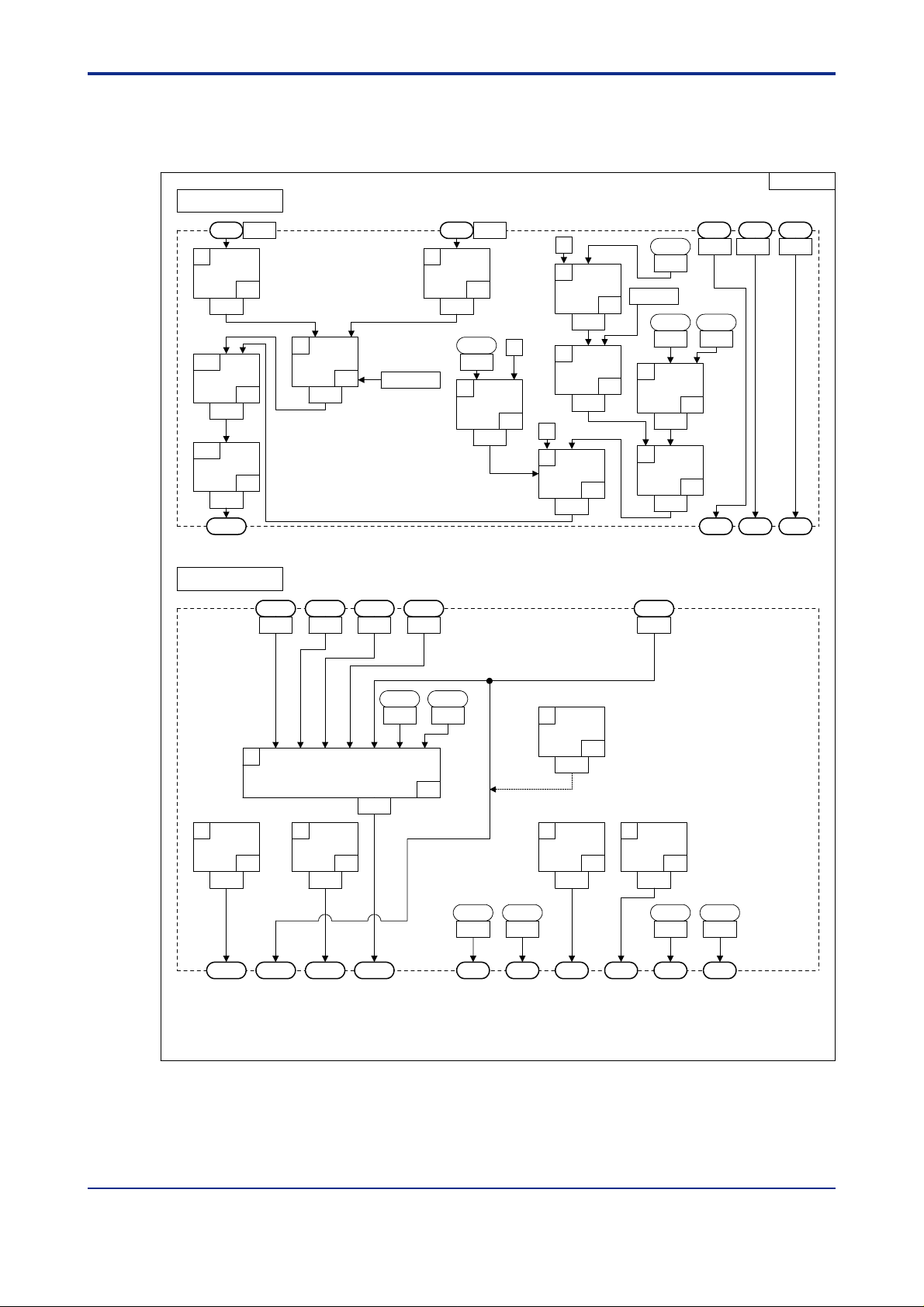
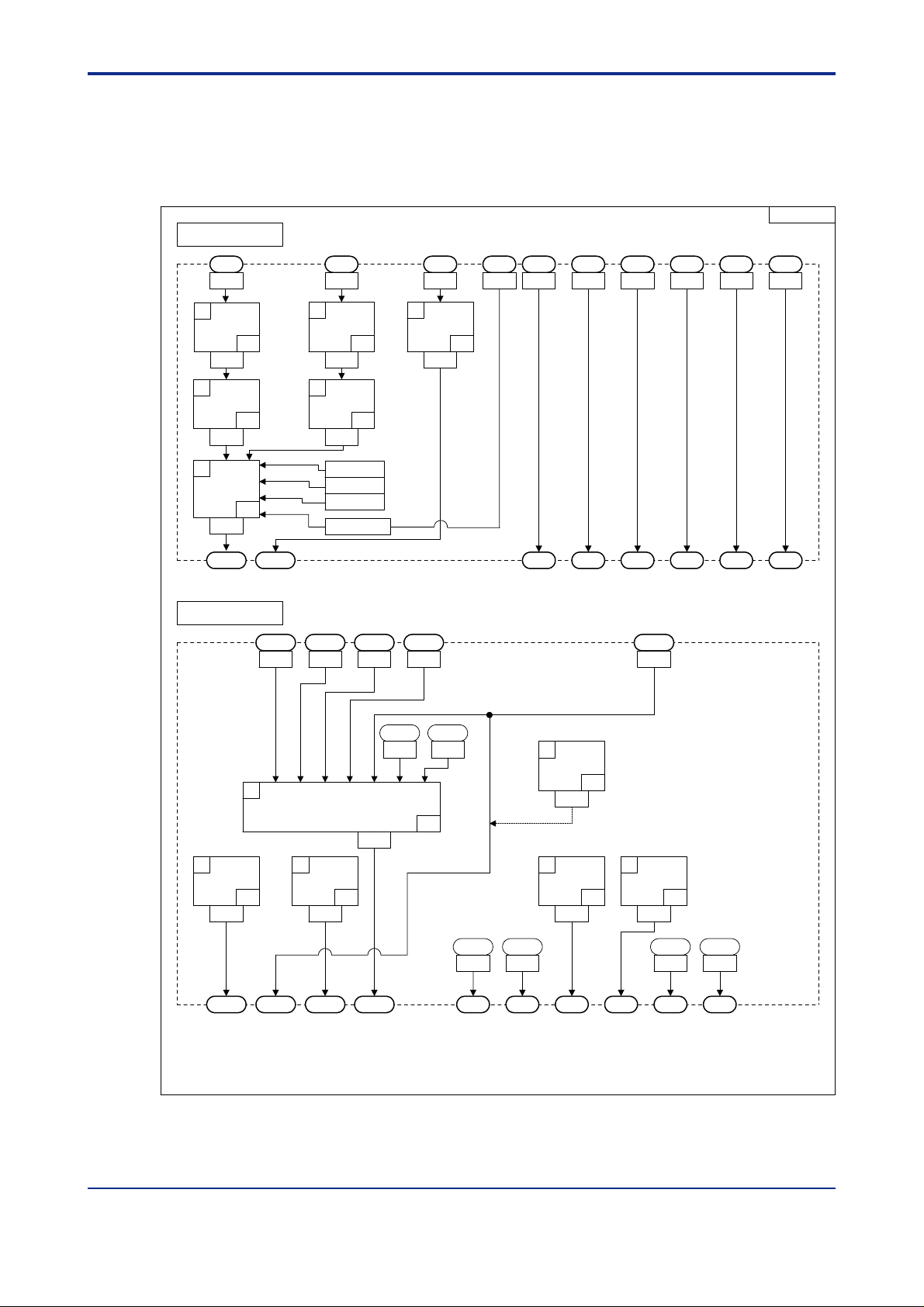
Figure 2.3 shows the whole view of the UT750’s functional structure, focusing on the
input/output blocks and signals that go in and out of the input/output blocks. This
figure thus clarifies where the input and output blocks are positioned within the
functionality of the UT750.
Figures 2.4 and after are diagrams of the input and output blocks for each controller
mode (UT mode).
2-1
IM 05G01B22-02E 3rd Edition : 2003.06.01-00
Page 16

<T oc> <Ind> <2. Computation Block Diagrams for Individual UT Modes >
■ Symbols and Names Used in UT750 Function Block Diagram
Names and symbols used in the UT750 function block diagram are as summarized below:
2-2
PV filter
IN1
AIN1
This symbol represents a function, and in this example means a PV filter.
This symbol represents a parameter (setup or operation parameter), and in this example
means analog input 1 type [IN1].
This symbol represents a signal fed to or from the input or output block, and in this
example means a signal fed to an input block [AIN1].
020001E.EPS
See Also
The UT750 User’s Manual for Single-loop Control (IM 05D01B02-01E to-05E) for the function names and
the parameters; and Chapter 3 of this manual, “Types and Ranges of Computation Data,” for custom
computation I/O signals.
IM 05G01B22-02E 3rd Edition : 2003.06.01-00
Page 17
<Toc> <Ind> <2. Computation Block Diagrams for Individual UT Modes >
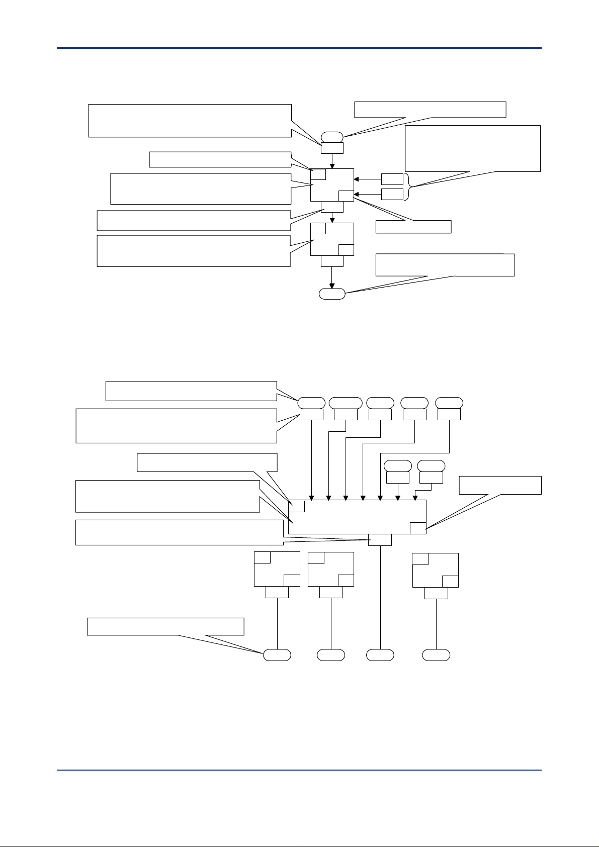
■ Symbols and Numbers Used in Computation Block Diagrams
• Diagram for Input Block
2-3
The number of the register or relay that stores the data of the input signal
indicated just above this number.
Numbers 1 to 1700 refer to D registers. [See Also] Sections 5.2 to 5.10.
Numbers 5001 to 7048 refer to I relays. [See Also] Sections 5.11 to 5.14.
Execution order number of the computation module.
Name of the computation module
[See Also] Chapter 4 for an explanation of the module’s function.
This example refers to module 41 code-named EUCONV
(EU Range Conversion).
The D register where the output of the computation module is stored.
[See Also] Section 5.2, which outlines the input-block data storage area.
Name of the computation module
[See Also] Chapter 4 for an explanation of the module’s function.
This example refers to module 33 code-named PLINE1
(Ten-segment Linearizer 1).
Figure 2.1 Explanation of an Input Block Diagram
• Diagram for Output Block
Input signal fed to the output block
The number of the register or relay that stores the data of the
input signal indicated just above this number.
Numbers 1 to 1700 refer to D registers.
Numbers 5001 to 7048 refer to I relays.
[See Also]
[See Also]
[See Also]
Section 3.4
Sections 5.2 to 5.10.
Sections 5.11 to 5.14.
Input signal fed to the input block [See Also] Section 3.2
AIN1
1301
IN1
1
EUCONV
41
Immediate
P1
P2
Settings for the module’s parameters that can be
specified to perform different actions.
[See Also] Chapter 4 for an explanation of the
module’s function
This example indicates that the immediate value
“0” is set into both parameters P1 and P2.
value
0
0
1401
2
PLINE1
IN1
Computation module number
33
1403
PVIN. 1
HOUT. 1 COUT.1OUT. 1
Destination of the output signal from the input block
[See Also]
Section 3.3.
RET1 RET2
1505 1507 1509 1511
020002E.EPS
1512
Execution order number of the computation module
Name of the computation module
[See Also]
Chapter 4 for an explanation of the module’s function.
This example refers to module 46 code-named OUTSEL1
(Loop-1 Output Selection 1).
The D register where the output of the computation module is stored.
[See Also]
Section 5.3, which outlines the output-block data storage area.
Destination of the output signal from the output block
[See Also]
Section 3.5.
Figure 2.2 Explanation of an Output Block Diagram
IN1
IN2 IN3 IN4 IN5 IN6 IN7
1
OUTSEL1
1601
2
OUTSEL11
1603
OUT1A OUT3A OUT1R
47
3
OUTSEL12
48
1605
ALO13
5691
ALO14
5693
46
4
OUTSEL13
1607
OUT2R
Computation module number
49
020003E.EPS
IM 05G01B22-02E 3rd Edition : 2003.06.01-00
Page 18
<T oc> <Ind> <2. Computation Block Diagrams for Individual UT Modes >
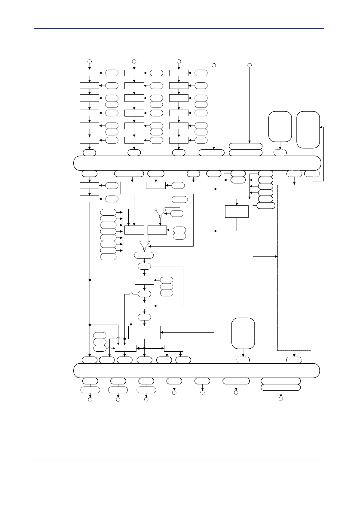
■ Function Block Diagram of UT750 (Whole View)
2-4
Measured input 1 Auxiliary analog inputMeasured input 2
Input type
selection
Unit
conversion
Range
conversion
Bias
Square-
root extraction
Filter
AIN1
PVIN1
Bias
Filter
IN1
UNI1
RH1
RL1
ABS1
ASR1
ALC1 ALC2 ALC3
AFL1
BS1
FL1
1.SP1
2.SP1
3.SP1
4.SP1
5.SP1
6.SP1
7.SP1
8.SP1
Input type
selection
Unit
conversion
Range
conversion
Bias
Square-
root extraction
Filter
AIN2
SP.0 to SP.3
Status input
processing
SP
selector
LR
SPH/SPL
TSP1
IN2
UNI2
RH2
RL2
ABS2
ASR2
AFL2
RSPIN1
Filter
RSP
Ratio/
bias
Input type
conversion
conversion
root extraction
Input block
COM
selection
Unit
Range
Bias
Square-
Filter
AIN3
RFL1
C.RSP1
RMS1
RT1
RBS1
Contact inputs
IN3
UNI3
RH3
RL3
ABS3
ASR3
AFL3
DI1 to DI7
R/L1
Status input
processing
(7 points)
GAIN1
Expanded contact inputs
(16 points)
RDI101 to RDI108
RDI201 to RDI208
TRG1
TRF1 CAS
Status input
processing
Used for cascade
secondary loop.
A/M1
AUTO
MAN
S/R
C.A.M
Any other
D registers
and I relays
(same as Loop 1)
Loop 2
DP1
DP2
MG1
MG2
MG3
MG4
RET1
RTH1
RTL1
PV1 RET1 OUT1
A1H/A1L A2H/A2L
Control output 1
(continuous)
Retransmission
output
CSP1
Control output 2
(continuous)
SP ramp
rate setting
CSP1
SUPER
SSP1
PID computation
A3H/A3L
Retransmission
output
TMU1
UPR1
DNR1
H/C output
COUT1HOUT1
Output block
Control output 1
(relay)
Control output 2
(relay)
Figure 2.3 Function Block Diagram of UT750 (Whole View)
Any other
D registers
and I relays
DO1 to DO7OUT2ROUT1ROUT3AOUT2AOUT1A
Contact outputs
(7 points)
RDO151 to RDO158
RDO251 to RDO258
Expanded contact outputs
(16 points)
020004E.EPS
IM 05G01B22-02E 3rd Edition : 2003.06.01-00
Page 19
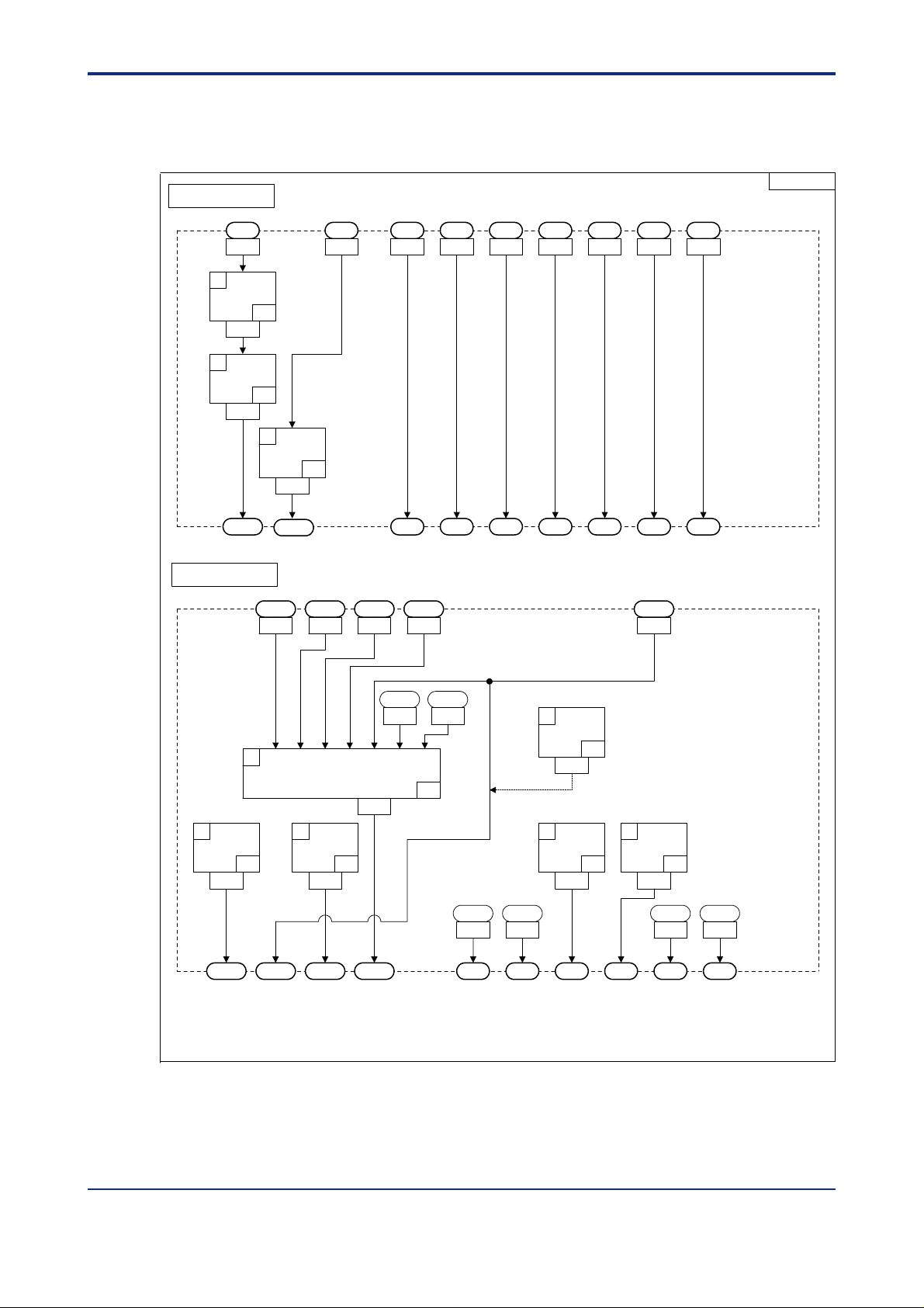
<Toc> <Ind> <2. Computation Block Diagrams for Individual UT Modes >
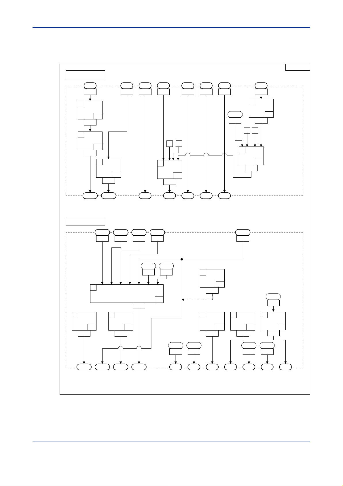
2.1 Input/Output Blocks for Single-loop Control (UT Mode 1)
2-5
Input Block
AIN1
1
EUCONV
1401
2
PLINE1
1403
PVIN1
Output Block
AIN3 DI1 DI2 DI3 DI4 DI5 DI6 DI7
13031301 5161 5162 5163 5164 5165 5166 5167
P1=0(A1)
P2=0(PV1)
41
33
3
EUCONV
1405
RSP1
1505 1507 1509 1511 1512
P1=2(A3)
P2=0(PV1)
41
SP.0 SP.1 SP.2 SP.3 A/M1 S/R R/L1
HOUT1 COUT1OUT1 RET1
RET2
UTM01
1
IN1
IN2 IN3 IN4 IN5 IN6 IN7
OUTSEL1
2
OUTSEL11
47
1603
OUT1A OUT2A OUT3A OUT1R
3
OUTSEL12
48
1605
ALO13
1601
5691
ALO14
5693
46
ALO11
5689
DO1 DO2 DO3 DO4 DO5 DO6
ALO12
5690
6
OUTSET2
61
1611
4
OUTSEL13
49
1607
P1=0
(OUT2A:mA)
5
OUTSEL14
1609
Figure 2.4 Input and Output Blocks for Single-loop Control (UT Mode 1)
50
ALO13
5691
ALO14
5693
020101E.EPS
IM 05G01B22-02E 3rd Edition : 2003.06.01-00
Page 20
<T oc> <Ind> <2. Computation Block Diagrams for Individual UT Modes >
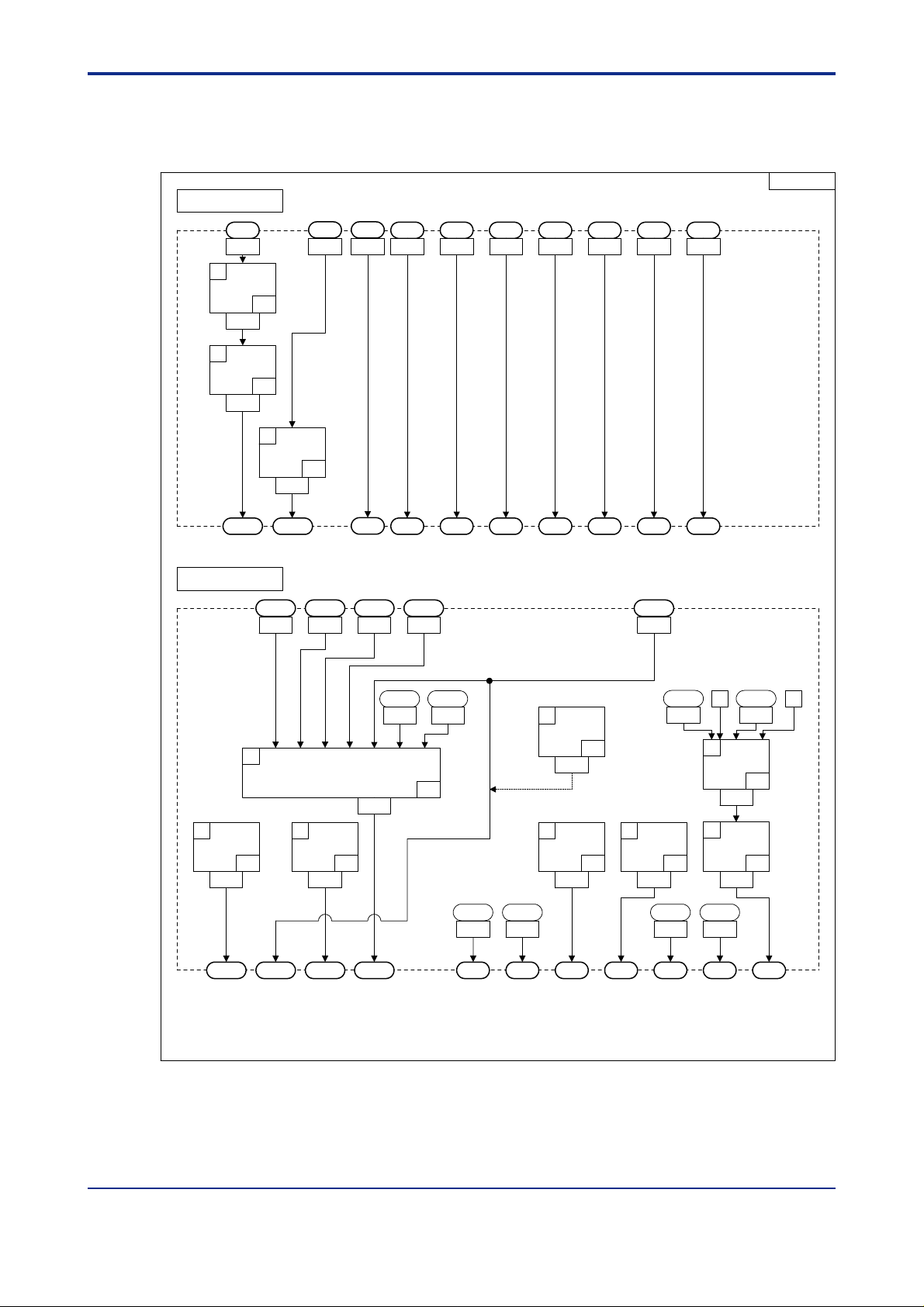
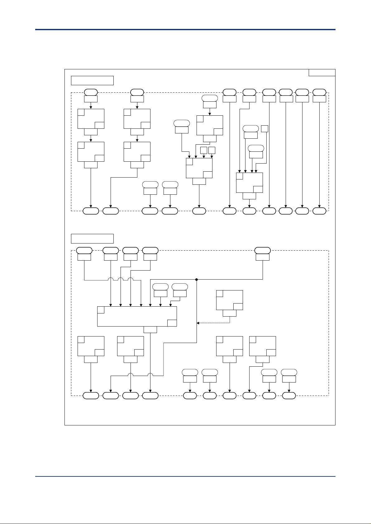
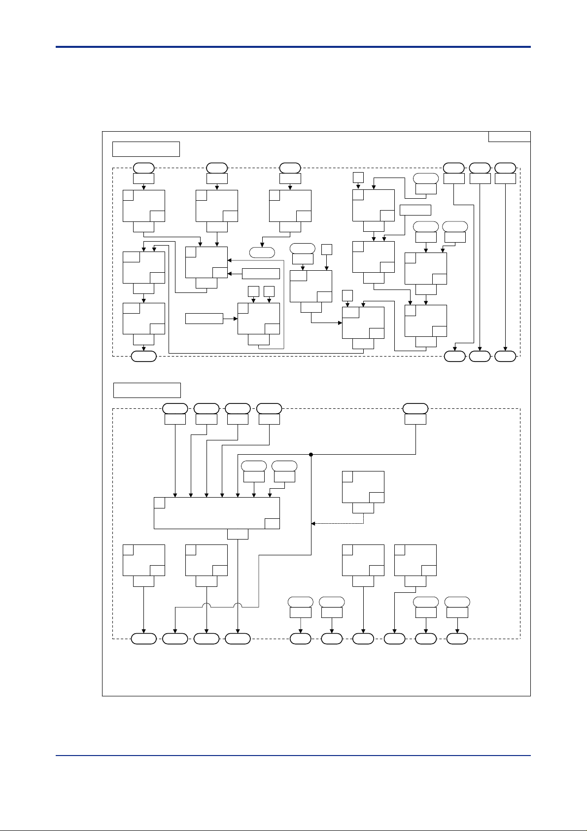
2.2 Input/Output Blocks for Cascade Primary-loop Control (UT Mode 2)
UTM02
Input Block
2-6
AIN1
1
EUCONV
1401
2
PLINE1
1403
PVIN1
Output Block
DI1 DI2 DI3 DI4 DI5 DI6 DI7
AIN3
AIN2
13031301 5161 5162 5163 5164 5165 5166 51671302
P1=0
(A1)
P2=0
41
(PV1)
33
3
EUCONV
1405
RSP1
1505 1507 1509 1511 1512
P1=1
(A2)
P2=0
41
(PV1)
TRK1
SP.0 SP.1 SP.2 SP.3 A/M1 S/R TRF1
HOUT1 COUT1OUT1 RET1 RET2
1
IN1
IN2 IN3 IN4 IN5 IN6 IN7
OUTSEL1
2
OUTSEL11
47
1603
OUT1A OUT2A OUT3A OUT1R
3
OUTSEL12
48
1605
1601
ALO13
5691
ALO14
5693
46
8
OUTSET2
1615
P1=0
(OUT2A:mA)
61
4
OUTSEL13
49
1607
ALO11
ALO12
5689
DO1 DO2 DO3 DO4 DO5 DO6 DO7
5690
PV1BO
5
OUTSEL14
1609
ALO13
5691
0 0
5018
6
7
50
ALO14
5693
Figure 2.5 Input and Output Blocks for Cascade Primary-loop Control (UT Mode 2)
AD1ERR
5001
OR
15
1611
NOT
17
1613
020201E.EPS
IM 05G01B22-02E 3rd Edition : 2003.06.01-00
Page 21
<Toc> <Ind> <2. Computation Block Diagrams for Individual UT Modes >
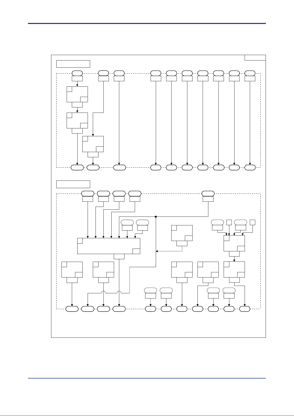
2.3 Input/Output Blocks for Cascade Secondaryloop Control (UT Mode 3)
Input Block
AIN3AIN1 DI1 DI2 DI3 DI4 DI5 DI7
13031301 5161 5162 5163 5164 5165 5167
2-7
UTM03
1
EUCONV
1401
2
PLINE1
1403
PVIN1
Output Block
1
2
OUTSEL11
47
1603
P1=0(A1)
P2=0(PV1)
41
6
46
OR
1411
ALO14
5693
0 0
15
7
OUTSET2
1613
4
OUTSEL13
1607
33
3
EUCONV
1405
RSP1
OUT1 RET1 RET2
1505 1507 1509 1511 1512
IN1
P1=2(A3)
P2=0(PV1)
41
CAS AUT MAN S/R MG1
HOUT1 COUT1
ALO13
5691
IN2 IN3 IN4 IN5 IN6 IN7
OUTSEL1
1601
3
OUTSEL12
48
1605
CAS
5069
P1=0
(OUT2A:mA)
61
49
5
5
OUTSEL14
1609
4
1 1
AND
1409
50
NOT
17
1407
14
CAS
5069
6
NOT
17
1611
OUT1A OUT2A OUT3A OUT1R
ALO11
ALO12
5689
5690
DO1 DO2 DO3 DO4 DO5 DO6 DO7
ALO13
5691
ALO14
5693
Figure 2.6 Input and Output Blocks for Cascade Secondary-loop Control (UT Mode 3)
IM 05G01B22-02E 3rd Edition : 2003.06.01-00
020301E.EPS
Page 22
<T oc> <Ind> <2. Computation Block Diagrams for Individual UT Modes >
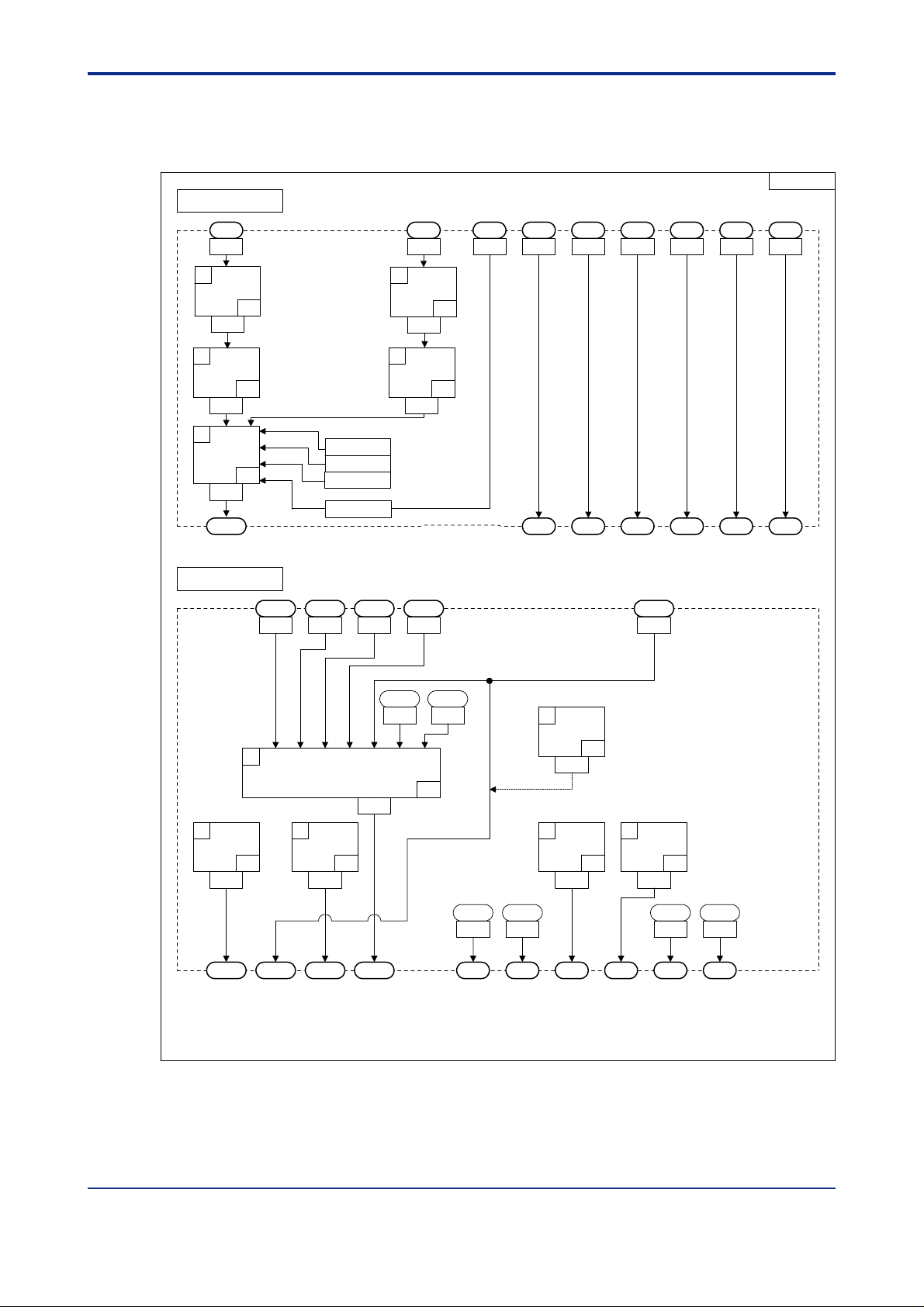
2.4 Input/Output Blocks for Cascade Control (UT Mode 4)
Input Block
2-8
UTM04
AIN3AIN1 DI1 DI2 DI3 DI4 DI5 DI6
13031301 5161 5162 5163 5164 5165 5166
41
33
P1=0
(A1)
P2=0
(PV1)
PVIN2
3
EUCONV
1405
4
PLINE2
1407
1
EUCONV
1401
2
PLINE1
1403
PVIN1
Output Block
OUT2RET1 RET2
1511 15121506 1508 1510
HOUT2 COUT2
41
34
OUT1
0005
RSP2
P1=2
(A3)
P2=1
(PV2)
CSP2
0020
TRK1
STOP
5067
7
5
OR
1413
TRF1
CAS
5069
NOT
1409
0 0
15
17
PV1BO
6
1411
CAS AUT MAN S/R R/L1 MG1
0
5018
AD1ERR
5001
OR
15
1
IN2 IN3 IN4 IN5 IN6 IN7
IN1
OUTSEL1
2
OUTSEL11
47
1603
OUT1A OUT2A OUT3A OUT1R
3
OUTSEL12
48
1605
ALO13
1601
5691
ALO14
5693
46
ALO11
5689
DO1 DO2 DO3 DO4 DO5 DO6
ALO12
5690
6
OUTSET2
61
1611
4
OUTSEL13
49
1607
P1=0
(OUT2A:mA)
5
OUTSEL14
Figure 2.7 Input and Output Blocks for Cascade Control (UT Mode 4)
1609
50
ALO13
5691
ALO14
5693
020401E.EPS
IM 05G01B22-02E 3rd Edition : 2003.06.01-00
Page 23
<Toc> <Ind> <2. Computation Block Diagrams for Individual UT Modes >
2.5 Input/Output Blocks for Loop Control for Backup (UT Mode 5)
Input Block
2-9
UTM05
1
EUCONV
1401
2
PLINE1
1403
PVIN1
Output Block
AIN2
P1=0
(A1)
P2=0
41
(PV1)
33
3
EUCONV
41
1405
RSP1
HOUT1 COUT1
OUT1 RET1 RET2
1505 1507 1509 1511 1512
AIN3AIN1
13031301 5161 5162 5163 5164 5165 5166 51671302
P1=1
(A2)
P2=0
(PV1)
TRK1
DI1 DI2 DI3 DI4 DI5 DI6 DI7
SP.0 SP.1 SP.2 SP.3
A/M1
S/R
TRF1
1
IN1
IN2 IN3 IN4 IN5 IN6 IN7
OUTSEL1
2
OUTSEL11
47
1603
OUT1A OUT2A OUT3A OUT1R
3
OUTSEL12
48
1605
ALO13
1601
5691
ALO14
5693
46
ALO11
5689
DO1 DO2 DO3 DO4 DO5 DO6 DO7
ALO12
5690
8
OUTSET2
61
1615
4
OUTSEL13
49
1607
P1=0
(OUT2A:mA)
PV1BO
5018
5
OUTSEL14
50
1609
ALO13
5691
Figure 2.8 Input and Output Blocks for Loop Control for Backup (UT Mode 5)
AD1ERR
0 0
5001
6
OR
15
1611
7
NOT
17
1613
ALO14
5693
020501E.EPS
IM 05G01B22-02E 3rd Edition : 2003.06.01-00
Page 24
<T oc> <Ind> <2. Computation Block Diagrams for Individual UT Modes >
2.6 Input/Output Blocks for Loop Control with PV Switching (UT Mode 6)
UTM06
Input Block
2-10
AIN1
1
PLINE1
33
1401
2
EUCONV
41
1403
5
SELECT2
42
1409
PVIN1
Output Block
AIN3
13031301 5161 5162 5163 5164 5165 51665167
3
PLINE2
1405
P1=0
(A1)
P2=0
(PV1)
P1
P2
P3
P4
HOUT1 COUT1OUT1
1505 1507 1509 1511 1512
P1=2
(A3)
P2=0
(PV1)
0703(U3)
0701(U1)
0702(U2)
5167(DI7)
4
EUCONV
1407
RET1 RET2
DI7
34
41
DI1 DI2 DI3 DI4 DI5 DI6
SP.0 SP.1 SP.2 SP.3
A/M1
S/R
1
IN1
IN2 IN3 IN4 IN5 IN6 IN7
OUTSEL1
2
OUTSEL11
47
1603
OUT1A OUT2A OUT3A OUT1R
3
OUTSEL12
48
1605
ALO13
1601
5691
ALO14
5693
46
ALO11
5689
DO1 DO2 DO3 DO4 DO5 DO6
ALO12
5690
6
OUTSET2
61
1611
4
OUTSEL13
49
1607
P1=0
(OUT2A:mA)
5
OUTSEL14
1609
50
ALO13
5691
ALO14
5693
Figure 2.9 Input and Output Blocks for Loop Control with PV Switching (UT Mode 6)
020601E.EPS
IM 05G01B22-02E 3rd Edition : 2003.06.01-00
Page 25
<Toc> <Ind> <2. Computation Block Diagrams for Individual UT Modes >
2.7 Input/Output Blocks for Loop Control with PV Auto-selector (UT Mode 7)
UTM07
Input Block
1
EUCONV
1401
10
ADD
1419
11
PLINE1
1421
PVIN1
41
33
AIN3AIN1 DI5 DI6
13031301
P1
P1
=0
0
4
SUB
2
1407
5
MUL
3
1409
0
9
SW
11
1417
P1=0
(A1)
P2=0
(PV1)
3
MINMAXAVE
1
1405
P1=2
P2
7
0701(U1)
2
EUCONV
1403
0701
8
41
U1
1415
P1=2
(A3)
P2=0
(PV1)
3
EQ
23
PRL1
1233
30000
PRH1
1232
6
SUB
1411
7
DIV
1413
2
4
DIn
PRL1
1233
SP.n
n=1,2,3,4
n=1,2,3,4
51665165516n
A/M1 S/R
2-11
Output Block
HOUT1 COUT1
OUT1 RET1 RET2
1505 1507 1509 1511 1512
1
IN1
IN2 IN3 IN4 IN5 IN6 IN7
OUTSEL1
2
OUTSEL11
47
1603
OUT1A OUT2A OUT3A OUT1R
3
OUTSEL12
1605
48
1601
ALO13
5691
ALO14
5693
46
ALO11
5689
DO1 DO2 DO3 DO4 DO5 DO6
ALO12
5690
6
OUTSET2
61
1611
4
OUTSEL13
49
1607
P1=0
(OUT2A:mA)
5
OUTSEL14
1609
ALO13
50
5691
ALO14
5693
Figure 2.10 Input and Output Blocks for Loop Control with PV Auto-selector (UT Mode 7)
IM 05G01B22-02E 3rd Edition : 2003.06.01-00
020701E.EPS
Page 26
<T oc> <Ind> <2. Computation Block Diagrams for Individual UT Modes >
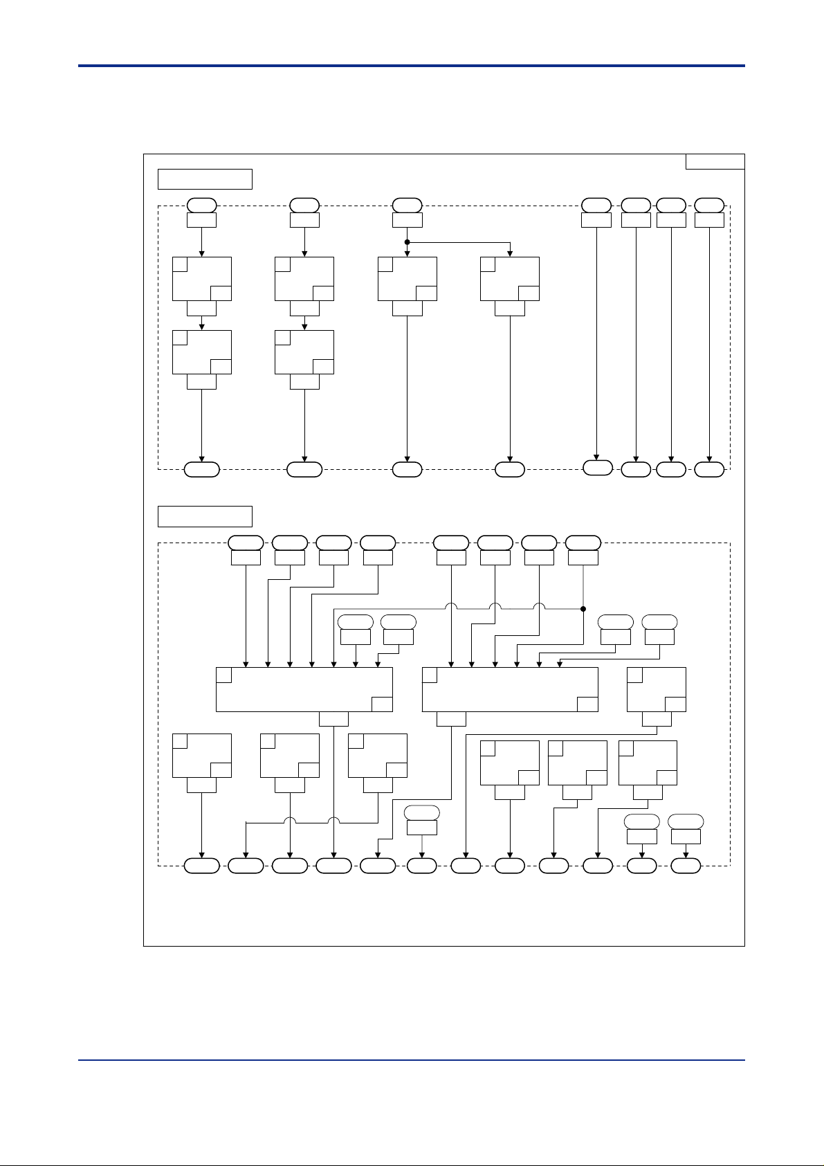
2.8 Input/Output Blocks for Dual-loop Control (UT Mode 1 1)
Input Block
AIN3AIN1 AIN2
13031301 51665165516n 51671302
n=1,2,3,4
DIn
DI5 DI6 DI7
2-12
UTM11
41
33
P1=0
(A1)
P2=0
(PV1)
1
EUCONV
1401
2
PLINE1
1403
PVIN1 PVIN2
Output Block
OUT1 RET1 OUT2 RET2
1505 1507 1509 1511 15121506 1508 1510
3
EUCONV
1405
4
PLINE2
1407
HOUT1
P1=1
(A2)
P2=1
41
(PV2)
34
COUT1 HOUT2 COUT2
ALO13
5691
5
EUCONV
1409
RSP1
ALO14
5693
41
P1=2
(A3)
P2=0
(PV1)
6
EUCONV
1411
RSP2
41
P1=2
(A3)
P2=1
(PV2)
SP.n
n=1,2,3,4
ALO12
5690
A/M1 A/M2
ALO21
5697
S/R
1
IN1
IN2 IN3 IN4 IN5 IN6 IN7
OUTSEL1
1601
2
OUTSEL11
47
1603
OUT1A OUT2A OUT3A OUT1R OUT2R
3
OUTSEL12
48
1605
7
OUTSEL21
46
1613
6
IN1
IN2 IN3 IN4 IN5 IN6
OUTSEL2
1611
4
52
ALO11
5689
DO1 DO2 DO3 DO4 DO5 DO6 DO7
OUTSEL13
1607
5
OUTSEL14
49
1609
Figure 2.11 Input and Output Blocks for Dual-loop Control (UT Mode 11)
IM 05G01B22-02E 3rd Edition : 2003.06.01-00
51
50
8
OUTSEL22
1615
9
OUTSEL23
54
1617
ALO22
5698
53
ALO23
5699
020801E.EPS
Page 27
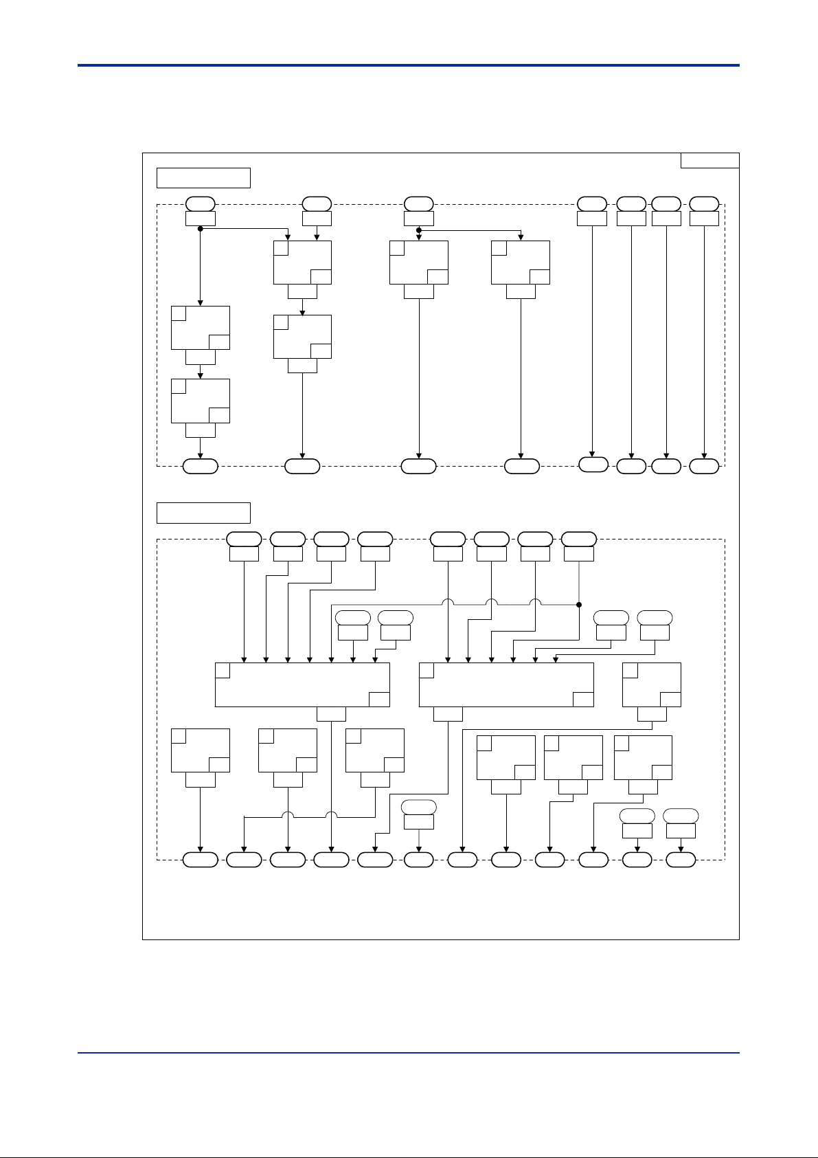
<Toc> <Ind> <2. Computation Block Diagrams for Individual UT Modes >
2.9 Input/Output Blocks for T emperature and Humidity Control (UT Mode 12)
Input Block
AIN3AIN1 AIN2 DI5 DI6 DI7
13031301 51665165516n 51671302
n=1,2,3,4
DIn
2-13
UTM12
41
33
P1=0
(A1)
P2=0
(PV1)
2
EUCONV
1403
3
PLINE1
1405
PVIN1 PVIN2
Output Block
OUT1 RET1 OUT2 RET2
1505 1507 1509 1511 15121506 1508 1510
1
TMPHUM
1401
4
PLINE2
1407
HOUT1
41
P1=2
(A3)
P2=0
(PV1)
6
EUCONV
41
1411
RSP2
P1=0(A1)
P2=1(A2)
P3=1(PV2)
43
34
COUT1 HOUT2 COUT2
ALO13
5691
5
EUCONV
1409
RSP1
ALO14
5693
P1=2
(A3)
P2=1
(PV2)
SP.n
n=1,2,3,4
ALO12
5690
A/M1 A/M2
ALO21
5697
S/R
1
IN1
IN2 IN3 IN4 IN5 IN6 IN7
OUTSEL1
1601
2
OUTSEL11
47
1603
OUT1A OUT2A OUT3A OUT1R OUT2R
3
OUTSEL12
48
1605
7
OUTSEL21
46
1613
6
IN1
IN2 IN3 IN4 IN5 IN6
OUTSEL2
1611
4
52
ALO11
5689
DO1 DO2 DO3 DO4 DO5 DO6 DO7
OUTSEL13
49
1607
51
5
OUTSEL14
1609
8
OUTSEL22
9
OUTSEL23
50
1617
ALO22
5698
53
1615
54
ALO23
5699
Figure 2.12 Input and Output Blocks for T emperature and Humidity Control (UT Mode 12)
IM 05G01B22-02E 3rd Edition : 2003.06.01-00
020901E.EPS
Page 28
<T oc> <Ind> <2. Computation Block Diagrams for Individual UT Modes >
2.10 Input/Output Blocks for Cascade Control with T wo Universal Inputs (UT Mode 13)
UTM13
Input Block
2-14
AIN2AIN1 DI1 DI2 DI3 DI4 DI5 DI6
1301 5161 5162 5163 5164 5165 51661302
41
33
P1=0
(A1)
P2=0
(PV1)
OUT1
0005
RSP2
3
EUCONV
1405
4
PLINE2
1407
CSP2
0020
TRK1
1
EUCONV
1401
2
PLINE1
1403
PVIN1 PVIN2
Output Block
RET1
1511 15121506 1508 1510
OUT2 RET2
HOUT2 COUT2
41
34
P1=1
(A2)
P2=1
(PV2)
P1=2
(A3)
P2=0
(PV1)
AIN3
1303
5
EUCONV
1409
RSP1
STOP
5067
41
8
7
OR
1415
TRF1
CAS
5069
NOT
1413
0 0
15
17
CAS AUT MAN S/R R/L1 MG1
PV1BO
6
1411
0
5018
AD1ERR
5001
OR
15
1
IN2 IN3 IN4 IN5 IN6 IN7
IN1
OUTSEL1
2
OUTSEL11
47
1603
OUT1A OUT2A OUT3A OUT1R
3
OUTSEL12
48
1605
ALO13
1601
5691
ALO14
5693
46
ALO11
5689
DO1 DO2 DO3 DO4 DO5 DO6
ALO12
5690
6
OUTSET2
61
1611
4
OUTSEL13
49
1607
P1=0
(OUT2A:mA)
5
OUTSEL14
1609
50
ALO13
5691
ALO14
5693
021001E.EPS
Figure 2.13 Input and Output Blocks for Cascade Control with T wo Universal Inputs (UT Mode 13)
IM 05G01B22-02E 3rd Edition : 2003.06.01-00
Page 29
<Toc> <Ind> <2. Computation Block Diagrams for Individual UT Modes >
2.1 1 Input/Output Blocks for Loop Control with PV Switching and T wo Universal Inputs (UT Mode 14)
UTM14
Input Block
2-15
1
PLINE1
33
1401
2
EUCONV
41
1403
5
SELECT2
42
1409
PVIN1
Output Block
AIN3AIN1 AIN2 DI1 DI2 DI3 DI4 DI5 DI6
13031301 5161 5162 5163 5164 5165 516651671302
3
PLINE2
34
1405
P1=0
(A1)
P2=0
(PV1)
RSP1
OUT1 RET1 RET2
1505 1507 1509 1511 1512
P1
P2
P3
P4
HOUT1 COUT1
4
EUCONV
41
1407
0703(U3)
0701(U1)
0702(U2)
5167(DI7)
6
EUCONV
1411
P1=0
(A1)
P2=0
(PV1)
DI7
41
P1=2
(A3)
P2=0
(PV1)
SP.0 SP.1 SP.2 SP.3 A/M1 S/R
1
IN1
IN2 IN3 IN4 IN5 IN6 IN7
OUTSEL1
2
OUTSEL11
47
1603
OUT1A OUT2A OUT3A OUT1R
3
OUTSEL12
48
1605
ALO13
1601
5691
ALO14
5693
46
ALO11
5689
DO1 DO2 DO3 DO4 DO5 DO6
ALO12
5690
6
OUTSET2
61
1611
4
OUTSEL13
49
1607
P1=0
(OUT2A:mA)
5
OUTSEL14
1609
50
ALO13
5691
ALO14
5693
Figure 2.14 Input and Output Blocks for Loop Control with PV Switching and T wo Universal
Inputs (UT Mode 14)
021101E.EPS
IM 05G01B22-02E 3rd Edition : 2003.06.01-00
Page 30
<T oc> <Ind> <2. Computation Block Diagrams for Individual UT Modes >
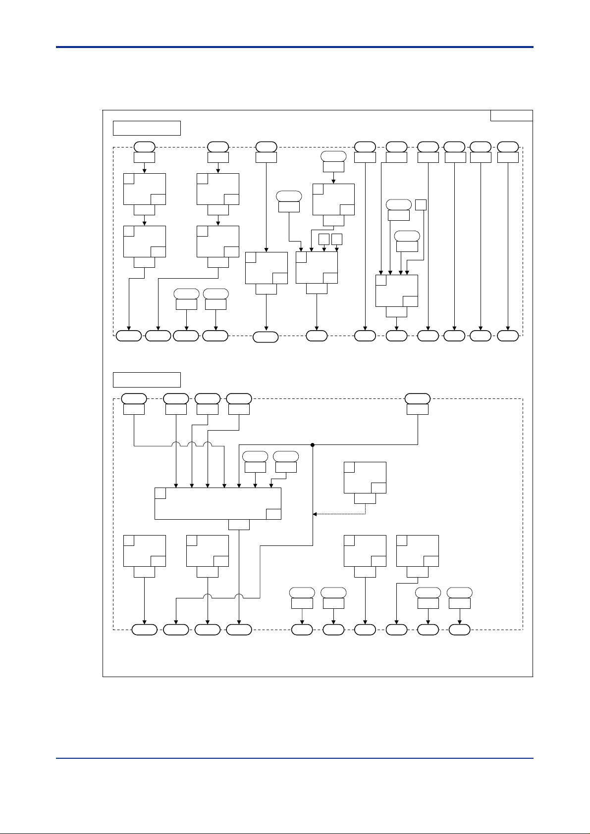
2.12 Input/Output Blocks for Loop Control with PV Auto-selector and T wo Universal Inputs (UT Mode 15)
UTM15
Input Block
1
EUCONV
1401
12
ADD
1423
13
PLINE1
1425
PVIN1
41
33
AIN3AIN1 AIN2 DI5 DI6
P1
P1
=0
0
6
SUB
1411
7
MUL
1413
0
11
SW
11
1421
30000
2
8
3
9
13031301 51665165516n1302
P1=0
(A1)
P2=0
(PV1)
1
2
EUCONV
1403
5
MINMAXAVE
1409
0702(U2)
P1=0 :2
P1=1 :3
P1=1
(A2)
P2=0
41
(PV1)
P1
7
P2
4
P1
RSP1
0701(U1)
2
3
SW
1407
3
EUCONV
1405
11
41
U1
0701
10
P1=2
(A3)
P2=0
(PV1)
3
EQ
23
1419
PRL1
1233
PRH1
1232
SUB
1415
DIV
1417
n=1,2,3,4
DIn
PRL1
1233
2
4
SP.n
n=1,2,3,4
A/M1 S/R
2-16
Output Block
OUT1
1
2
OUTSEL11
47
1603
OUT1A OUT2A OUT3A OUT1R
HOUT1 COUT1
1505 1507 1509 1511 1512
IN1
IN2 IN3 IN4 IN5 IN6 IN7
OUTSEL1
3
OUTSEL12
1605
48
1601
RET1 RET2
ALO13
5691
ALO14
5693
46
ALO11
5689
DO1 DO2 DO3 DO4 DO5 DO6
6
OUTSET2
61
1611
4
OUTSEL13
49
1607
ALO12
5690
P1=0
(OUT2A:mA)
5
OUTSEL14
1609
ALO13
5691
50
ALO14
5693
021201E.EPS
Figure 2.15 Input and Output Blocks for Loop Control with PV Auto-selector and Two Universal
Inputs (UT Mode 15)
IM 05G01B22-02E 3rd Edition : 2003.06.01-00
Page 31

<Toc> <Ind> <3. T ypes and Ranges of Computation Data >
3. T ypes and Ranges of Computation Data
This chapter explains the types of computation data used in the input and output
blocks, and their ranges. When you configure custom computations, you must make
sure they comply with the specific types of computation data, such as range data,
scale data and percentage-type data, which are fed to/from the input and output
blocks. Y ou can verify the computation data types in this chapter.
Figure 3.1 below shows an example of data flow where data taken in through analog input
1 (AIN1) is fed first to the EU Range Conversion (EUCONV) module and then the Tensegment Linearizer 1 (PLINE1) module, for computation. The resulting data is then passed
to the PVIN.1 signal of the loop 1 control-and-computing section.
If the AIN1 analog input is a thermocouple (TC) input or a resistance temperature detector
(RTD) input, the input data has a value ranging from the minimum value of the analog input
1 range (RL) to the maximum value of the analog input 1 range (RH), which corresponds to
the internal data range from 0 to 30000.
If AIN1 is a voltage input, the input data has a value ranging from the minimum value of the
analog input 1 scale (SL) to the maximum value of the analog input 1 scale (SH), which
corresponds to the internal data range from 0 to 30000.
The PVIN.1 signal has a value ranging from 0 to 30000, which is an internal value obtained
by converting a value ranging from the minimum value of the PV1 range (P.RL1) to the
maximum value of the PV1 range (P.RH1).
3-1
Input signal fed to the input block:
If the AIN1 analog input is a TC input or an RTD
input, it takes a data value ranging from RL1 to RH1.
If AIN1 is a voltage input, it takes a data value
ranging from SL to SH (setup parameters).
Module’s output data:
This register has a data value converted to within
the range of the PVIN.1, which is set by the P2
parameter of the EUCONV module.
Figure 3.1 Data Flow
AIN1
1301
IN1
1
EUCONV
1401
IN1
2
PLINE1
1403
PVIN. 1
Parameter settings for the computation module:
The EUCONV module automatically matches the data types
according to the settings of the P1 and P2 parameters.
P1 = 0: the module obtains data from analog input 1(AIN1).
P2 = 0: the module passes the data to PVIN.1
(to loop-1 control computation).
P1
P2
41
33
0
0
Output signal fed from the input block:
This is a data value ranging from 0 to 30000 that
corresponds to the P.RL1 to P.RH1 range, in
which the data should be passed to the controland-computing section.
030001E.EPS
IM 05G01B22-02E
3rd Edition : 2003.06.01-00
Page 32

<T oc> <Ind> <3. Types and Ranges of Computation Data >
3.1 T ypes of Computation Data
The types of computation data used for custom computations are classified in the following
table.
The table also summarizes the displayed values and the corresponding internal values,
hereinafter referred to as computation data. See the next section for the data type of the I/O
data of the input and output blocks.
3-2
Actual Range of DataData Type
Range Minimum to maximum values
Scale Minimum to maximum values
%
Gain
Flag
Integer No specific range
*1: This range corresponds to -5.0% to 105.0%.
of the range
of the scale
0.0 to 100.0% -1500 to 31500
0.001 to 10.000 1 to 10000 Gain setting only The displayed data value of 0.001 to
0 or 1 0 or 1
(Readout range is -19999 to
30000)
Integer data is normally used to configure your own custom computations. It is signed 2byte (16 bits) data, with a value limited to the ±30000 range. Y ou can use data of up to 4byte (32 bits) data with a plus or minus sign, however, with some of the computation modules such as those for four arithmetic operations. For example, these modules can have
the result of multiplying 2-byte data by 2-byte data as 4-byte data. In that case, the result is
stored in two D registers (e.g., the MO1L register [lower-order word] and the MO1H register
[higher-order word]).
Data
-1500 to 31500
(*1)
-1500 to 31500
(*1)
(*1)
-30000 to 30000
RemarksData IncludedComputation
Analog input, measured
input, and others
Voltage input The scale is determined by SL and
Tracking input, control
output, and others
Flags for control and others
Internal data without unit.
All parameter settings
belong to this type.
The range is determined by RL and
RH setup parameters.
SH setup parameters.
The displayed data value of 0.0% to
100.0% corresponds to the
computation data value of 0 to 30000
10.000 corresponds to the
computation data value of 1 to
10000
0 represents OFF; 1 represents ON.
Out of -30000 to 30000 range, the
portion of -19999 to 30000 can be
shown on the controller.
The RH value of 1500.0 corresponds to
the computation data value of 15000.
030101E.EPS
See Also
UT750 User’s Manual for Single-loop Control (IM 05D01B02-01E to-05E) for setup parameters RL, RH,
P.RL, P .RH, SL and SH.
IM 05G01B22-02E
3rd Edition : 2003.06.01-00
Page 33

<Toc> <Ind> <3. T ypes and Ranges of Computation Data >
3.2 Data Fed to the Input Block
The following table lists the data types and computation data used with the data items that
are fed to the input block. When connecting computation modules to the input signals fed to
the input block, check which data type and computation data apply .
3-3
Input
Signal
Code
D Register
Number
or I Relay
Number
Description Data
Type
Range
Specifications
Computation
Data
Remarks
This data item uses the RH1 and RL1
The computation data value of 0 is
equivalent to RL1 and
range setting parameters.
30000 to RH1.
AIN1
1301
Analog input 1
Scale
This data item uses the SH1 and SL1
The computation data value of 0 is
scale setting parameters.
equivalent to SL1 and
30000 to SH1.
AIN2
1302
Analog input 2
Range
Scale
-1500 to
31500 (*1)
This data item uses the RH2 and RL2
The computation data value of 0 is
30000 to RH2.
This data item uses the SH2 and SL2
The computation data value of 0 is
range setting parameters.
equivalent to RL2 and
scale setting parameters.
equivalent to SL2 and
30000 to SH2.
AIN3
1303
Analog input 3
Scale
This data item uses the SH3 and SL3
The computation data value of 0 is
scale setting parameters.
equivalent to SL3 and
30000 to SH3.
DI1
DI2
DI3
DI4
DI5
DI6
DI7
RDI101
RDI102
RDI103
RDI104
RDI105
RDI106
RDI107
RDI108
RDI201
RDI202
RDI203
RDI204
RDI205
RDI206
RDI207
RDI208
5161
5162
5163
5164
5165
5166
5167
5177
5178
5179
5180
5181
5182
5183
5184
5185
5186
5187
5188
5189
5190
5191
5192
Contact input 1
Contact input 2
Contact input 3
Contact input 4
Contact input 5
Contact input 6
Contact input 7
Expansion module 1 contact input 1
Expansion module 1 contact input 2
Expansion module 1 contact input 3
Expansion module 1 contact input 4
Expansion module 1 contact input 5
Expansion module 1 contact input 6
Expansion module 1 contact input 7
Expansion module 1 contact input 8
Expansion module 2 contact input 1
Expansion module 2 contact input 2
Expansion module 2 contact input 3
Expansion module 2 contact input 4
Expansion module 2 contact input 5
Expansion module 2 contact input 6
Expansion module 2 contact input7
Expansion module 2 contact input 8
Flag
0 or 1
The computation data value of 0 is equivalent to “off” and
1 to “on.”
*1: This computation data range of AIN1, AIN2, and AIN3 is equivalent to -5.0% to 105.0% of the ranges RL1 to RH1, SL1 to
SH1, RL2 to RH2, SL2 to SH2, and SL3 to SH3.
030201E.EPS
IM 05G01B22-02E
3rd Edition : 2003.06.01-00
Page 34

<T oc> <Ind> <3. Types and Ranges of Computation Data >
3.3 Data Fed from the Input Block
The following table lists the data types and computation data used with the data items that
are fed from the input block. When connecting computation modules to the output signals
fed from the input block, check which data type and computation data apply .
NOTE
Depending on the input-block custom computation you configure, the resulting data may be
out of the 0 to 30000 range. In order to match the data range to the range defined by the
P.RL and P.RH parameters of the UT750, configure custom computations using the data
ranges shown in the following table.
3-4
Output
Signal
Code
PVIN.1
PVIN.2
PSPIN.1
PSPIN.2
GAIN.1
GAIN.2
D Register
Number
1331
1332
1333
1334
1335
1336
Specifications
Description Data Type Computation
Loop 1 PV input
Loop 2 PV input
Range
Loop 1 remote
setpoint input
Loop 2 remote
setpoint input
Loop 1 gain
setting value
Gain
(ABS)
Loop 2 gain
setting value
Data
-1500 to
31500 (*1)
0 to 30000
0 to 10000
Remarks
This data item uses the P.RH1 and P.RL1 range
setting parameters.
The computation data value of 0 is equivalent to
P.RL1 and 30000 to P.RH1.
This data item uses the P.RH2 and P.RL2 range
setting parameters.
The computation data value of 0 is equivalent to
P.RL2 and 30000 to P.RH2.
This data item uses the P.RH1 and P.RL1 range
setting parameters.
The computation data value of 0 is equivalent to
P.RL1 and 30000 to P.RH1.
This data item uses the P.RH2 and P.RL2 range
setting parameters.
The computation data value of 0 is equivalent to
P.RL2 and 30000 to P.RH2.
The controller carries outPID control using a
proportional band divided by the gain.
If the gain is 0, no gain-based action is taken.
If the computation data is
the actual data
times the given proportional band.
is in the range of 0.001 to 10.000
in the 1 to10000 range,
*1: Corresponds to -5.0% to 105.0% of the ranges P.RL1 to P.RH1 and P.RL2 to P.RH2.
IM 05G01B22-02E
030301E.EPS
3rd Edition : 2003.06.01-00
Page 35

<Toc> <Ind> <3. T ypes and Ranges of Computation Data >
Continued from the previous table
3-5
Output
Signal
Code
TRG.1
TRG.2
D Register
Number
1337
1338
Specifications
Description Data Type Computation
Data
Loop 1
tracking input
%
-1500 to 31500
(*1)
Loop 2
tracking input
Remarks
This input accepts the 0.0 to 100.0% range of an
input signal as data in the 0 to 30000 range.
When TRF.1 is on, the input block feeds the
value of TRG.1 regardless of whether loop 1 is in
AUTO mode or MAN mode.
When TRF.1 changes from on to off, the
controller resumes the AUTO mode or MAN
mode operation using the TRG.1 value
immediately before the status change.
Manual output is possible when the loop is in the
MAN mode.
This input accepts the 0.0 to 100.0% range of an
input signal as data in the 0 to 30000 range.
When TRF.2 is on, the input block feeds the
value of TRG.2 regardless of whether loop 2 is in
the AUTO mode or MAN mode.
When TRF.2 changes from on to off, the
controller resumes the AUTO mode or MAN
mode operation using the TRG.2 value
immediately before the status change.
Manual output is possible when the loop is in the
MAN mode.
TRF.1
TRF.2
1339
1340
Loop 1
tracking flag
Loop 2
tracking flag
*1: Corresponds to -5.0% to 105.0%.
Flag
1: Tracking is on.
0: Tracking is off.
0 or 1
1: Tracking is on.
0: Tracking is off.
030302E.EPS
IM 05G01B22-02E
3rd Edition : 2003.06.01-00
Page 36

<T oc> <Ind> <3. Types and Ranges of Computation Data >
Continued from the previous table
3-6
Output
Signal
Code
DP1
DP2
D Register
Number
1378
1379
Specifications
Description Data Type Computation
Data
Operating
display
selection 1
Flag 0 or 1
Operating
display
selection 2
Remarks
A transition in this signal from 0 to 1 switches the
operating display. The operating displays you can
view by interrupting the current display are as
follows:
1) SP display
2) OUT display
3) Deviation trend display
4) Data list display
5) Heating/cooling OUT display
6) Heating/cooling data list display
7) Timer value display
8) Loop 1 SP display
9) Loop 1 OUT display
10) Loop 1 Deviation trend display
11) Loop 1 Data list display
12) Loop 1 Heating/cooling OUT display
13) Loop 1 Heating/cooling data list display
14) Loop 1 Timer value display
15) Loop 2 SP display
16) Loop 2 OUT display
17) Loop 2 Deviation trend display
18) Loop 2 Data list display
19) Loop 2 Heating/cooling OUT display
20) Loop 2 Heating/cooling data list display
21) Loop 2 Timer value display
22) PV2 display
23) PV/SP/OUT2 display
24) Heating/cooling PV/SP/OUT2 display
25) DISP display
26) Analog input display
27) Unilluminated operating display
[See Also]
Section 6.1, “List of Operating Displays and Their
Descriptions”
Select the operating display to be switched to at the
Operating Display Selection of the LL200.
By turning on the contact registered with the DP1 or
DP2 setup parameter, you can view the operating
display registered with the display switching
condition of “DP1 = on” or “DP2 = on,” regardless
of the current display.
[See Also]
Section 6.3, “Display Switching Conditions for
Operating Displays”
MG1
MG2
MG3
MG4
1380
1381
1382
1383
Interruptive
message
display 1
Interruptive
message
display 2
Interruptive
message
display 3
Interruptive
message
display 4
Flag 0 or 1
Displays messages on the LCD display.
Edit the message text using the Parameters Setting
Tool.
If any of these signal flags turns on, the
corresponding message appears on the UT750’s
LCD display (messages 1 to 4 will be shown in the
first to the 4th lines on the display).
You can clear the message shown by pressing the
DISP key on the controller, and the controller
returns to the normal display.
[See Also]
User's manual of LL100 PC-based Parameters
Setting Tool (IM 05G01B12-01E) for how to set
messages.
030303E.EPS
IM 05G01B22-02E
3rd Edition : 2003.06.01-00
Page 37

<Toc> <Ind> <3. T ypes and Ranges of Computation Data >
Continued from the previous table
3-7
Output
Signal
Code
A/M1
A/M2
R/L1
R/L2
S/R
CAS
AUT
MAN
SP.0
SP.1
D Register
Number
1343
1344
1345
1346
1347
1348
1349
1350
1351
1352
Description Data Type Computation
Data
Loop 1
AUTO/MAN
mode
Loop 2
AUTO/MAN
mode
Loop 1
Remote/Local
mode
Loop 2
Remote/Local
mode
Stop/Run
Flag
0 or 1
Cascade mode
AUTO mode
MAN mode
Bit 0 of SP
number
selection
Bit 1 of SP
number
selection
Specifications
Remarks
1: AUTO
0: MAN
When the value is “1,” the mode cannot be switched
by key operation. (Toggle switch)
1: AUTO
0: MAN
When the value is “1,” the mode cannot be switched
by key operation. (Toggle switch)
1: REMOTE
0: LOCAL
When the value is “1,” the mode cannot be switched
by key operation. (Toggle switch)
1: REMOTE
0: LOCAL
When the value is “1,” the mode cannot be switched
by key operation. (Toggle switch)
0: RUN
1: STOP
A toggle switch (The mode can be switched by key
operation only when the D-register for DI
assignment D1133 = 0.)
A transition in this signal from 0 to 1 switches to
cascade control. (*1)
(One-shot switch)
A transition in this signal from 0 to 1 switches to
automatic control. (*1)
(One-shot switch)
A transition in this signal from 0 to 1 switches to
manual control. (*1)
(One-shot switch)
A switch is made between SP numbers using on-off
combinations of these four bits.
0: Setting by key operation is valid.
1 to 8: Setting by contacts is valid
By using contact inputs, SP number is set with a
binary string.
Bit 2 of SP
SP.2
1353
number
selection
Bit 3 of SP
SP.3 1354
number
selection
*1: Used in cascade secondary-loop control or internal cascade control.
[TIP]
If the contact inputs are “DI4 = off, DI3 = on,
DI2 = off, and DI1 = on,” which is represented as
“0101” in binary system and as “5” in the decimal
system, then SP number 5 (5.SP) is selected.
030304E.EPS
IM 05G01B22-02E
3rd Edition : 2003.06.01-00
Page 38

<T oc> <Ind> <3. Types and Ranges of Computation Data >
3.4 Data Fed to the Output Block
The following table lists the data types and computation data used with the data items that
are fed to the output block. When connecting computation modules to the input signals fed
to the output block, check which data type and computation data apply .
3-8
Input
Signal
Code
PV.1
PV.2
CSP.1
CSP.2
OUT.1
OUT.2 1506 Loop 2
HOUT.1 1507
HOUT.2 1508
COUT.1 1509
COUT.2 1510 Loop 2
D Register
Number
1501
1502
1503
1504
1505 Loop 1
Description Data Type Computation
Loop 1 PV
Loop 2 PV
Loop 1 SP
Loop 2 SP
control output
control output
heating-side
control output
heating-side
control output
cooling-side
control output
cooling-side
control output
Loop 1
Loop 2
Loop 1
Range
%
Specifications
Data
-1500
to
31500
(*1)
0 to 30000
-1500
to
31500
(*2)
Remarks
This data item uses the P.RH1 and P.RL1
range setting parameters.
The computation data value of 0 is equivalent to
P.RL1 and 30000 to P.RH1.
This data item uses the P.RH2 andP.RL2
range setting parameters.
The computation data value of 0 is equivalent to
P.RL2 and 30000 to P.RH2.
This data item uses the P.RH1 and P.RL1
range setting parameters.
The computation data value of 0 is equivalent to
P.RL1 and 30000 to P.RH1.
This data item uses the P.RH2 and P.RL2
range setting parameters.
The computation data value of 0 is equivalent to
P.RL2 and 30000 to P.RH2.
The computation data value of 0 is equivalent to
0.0% and 30000 to 100.0%.
*1: Corresponds to -5.0% to 105.0% of the ranges P.RL1 to P.RH1 and P.RL2 to P.RH2.
*2: Corresponds to -5.0% to 105.0%. Upon heating/cooling control, OUT1 and OUT2 range from -3150 to 31500.
IM 05G01B22-02E
3rd Edition : 2003.06.01-00
030401E.EPS
Page 39

<Toc> <Ind> <3. T ypes and Ranges of Computation Data >
Continued from the previous table
3-9
Input
Signal
Code
RET1
RET2
D Register
Number
1511
1512
Description Data Type Computation
Retransmission
output 1
Retransmission
output 2
*1: Corresponds to -5.0% to 105.0%
Range
%
Range
%
Specifications
Data
-1500
to
31500
(*1)
Remarks
This data item uses the RTH1 and RTL1 range
setting parameters.
The computation data value of 0 is equivalent to
RTL1 and 30000 to RTH1.
This data item changes to % type data if the RET1
setup parameter equals OUT1 or OUT2.
The computation data value of 0 is equivalent to
0.0% and 30000 to 100.0%.
This data item uses the RTH2 and RTL2
range setting parameters.
The computation data value of 0 is equivalent to
RTL2 and 30000 to RTH2.
This data item changes to % type data if the RET2
setup parameter equals OUT1 or OUT2.
The computation data value of 0 is equivalent to
0.0% and 30000 to 100.0%.
030402E.EPS
IM 05G01B22-02E
3rd Edition : 2003.06.01-00
Page 40

<T oc> <Ind> <3. Types and Ranges of Computation Data >
3.5 Data Fed from the Output Block
The following table lists the data types and computation data used with the data items that
are fed from the output block. When connecting computation modules to the output signals
fed from the output block, check which data type and computation data apply .
3-10
Output
Signal
Code
OUT1A
OUT2A
OUT3A
OUT1R
OUT2R 1535
DO1 1536
DO2 1537
DO3 1538
DO4 1539
DO5 1540
DO6 1541
DO7 1542
*1: Corresponds to -5.0% to 105.0%
D Register
Number
1531
1532
1533
1534
Description Data Type Computation
Control output 1
(current/voltage
pulse)
Control output 2
(current/voltage
pulse)
Analog output 3
(voltage)
Control output 1
(relay)
Control output 2
(relay)
Contact output 1
(relay)
Contact output 2
(relay)
Contact output 3
(relay)
Contact output 4
(open collector)
Contact output 5
(open collector)
Contact output 6
(open collector)
Contact output 7
(open collector)
%
%
Flag
%
Flag
Flag
Specifications
Data
-1500
to
31500
(*1)
0 or 1
Remarks
Voltage output or current pulse output
Voltage output
If this data item is time proportional output, the
computation data value of 0 is equivalent to 0.0%
and 30000 to 100.0%.
If this data item is on-off output, it works like flag
data.
The computation data value of 0 is equivalent to
0.0% (off) and 30000 to 100.0% (on).
The computation data value of 0 is equivalent to off
and 1 to on.
030501E.EPS
IM 05G01B22-02E
3rd Edition : 2003.06.01-00
Page 41

<Toc> <Ind> <3. T ypes and Ranges of Computation Data >
Continued from the previous table
3-11
Signal
Code
RDO151
RDO152
RDO153
RDO154
RDO155
RDO156
RDO157
RDO158
RDO251
RDO252
RDO253
RDO254
RDO255
RDO256
RDO257
RDO258
D Register
Number
or I Relay
Number
1543
1544
1545
1546
1547
1548
1549
1550
1551
1552
1553
1554
1555
1556
1557
1558
Description
Expansion module 1 contact output 1
Expansion module 1 contact output 2
Expansion module 1 contact output 3
Expansion module 1 contact output 4
Expansion module 1 contact output 5
Expansion module 1 contact output 6
Expansion module 1 contact output 7
Expansion module 1 contact output 8
Expansion module 2 contact output 1
Expansion module 2 contact output 2
Expansion module 2 contact output 3
Expansion module 2 contact output 4
Expansion module 2 contact output 5
Expansion module 2 contact output 6
Expansion module 2 contact output 7
Expansion module 2 contact output 8
Data Type
Flag
SpecificationsInput
Computation
Data
0 or 1
Remarks
The computation data value of 0 is
equivalent to off, and 1 to on.
030502E.EPS
NOTE
• T o implement time-proportional output, you must use the Control Output Selection
modules (module Nos. 46 to 54). However, it is recommended that you use the output
blocks of the standard controller modes (UT modes) as they are.
• T o implement current output, you must use the Output Terminal Configuration modules (module Nos. 60 and 61).
IM 05G01B22-02E
3rd Edition : 2003.06.01-00
Page 42

Blank Page
Page 43

<Toc> <Ind> <4. List of Computation Modules and Their Functions >
4. List of Computation Modules and Their Functions
This chapter explains the function specifications of each computation module. A list
of the modules is presented first, and then the functions of each module are described.
The following paragraphs explain some of the specifications that appear throughout
this chapter.
■ IN1 to IN8, P1 to P4, OUT
IN1 to IN8 represent the inputs of each computation module, P1 to P4 are the module
parameters and OUT is the output. The following symbols are used to indicate the size of
data that have functional assignments within each module.
: 4-byte data (two words)
: 2-byte data (one word)
: Flag data (0 or 1)
4-1
NOTE
Some computation modules have their “OUT” marked with the symbol “⫻” which indicates
that they themselves do not output any data. Output registers of such modules store the
same data as that of their immediately preceding (in the execution order) module.
■ Work Area
Some computation modules require a “work area,” whose size is indicated with a number .
Y ou can use work areas up to a total size of 240. You cannot register computation modules
that use work areas exceeding 240.
■ Limitation on Use
Computation modules with limited usage are given a number that indicates the number of
times it can be used.
IM 05G01B22-02E
3rd Edition : 2003.06.01-00
Page 44

<T oc> <Ind> <4. List of Computation Modules and Their Functions >
4.1 How to Hold Outputs at Power Failure and
Recovery Using Custom Computation
■ Example: Holding the Output V alue of SUM Module
Step 1) Save the output data value of a module into D1041 to D1050 (for word data) or
D1051 to D1060 (for long word data) by using the No. 78 Data Save module.
IN1 IN2
SUM
OUT
Data output to
DATASAVE
4-2
IN1
DATASAVE
P1
1051(LDATA1L)
P2
1
040101E.EPS
IN1 of DA TASAVE: Input of DAT ASAVE. In this example, input the output of SUM.
P1 of DA TASAVE: Specifies the register where the data is saved. Since SUM outputs
long word data, specify D1051 (LDA TA1L).
P2 of DA TASAVE: Always set to “1” (write-enabled).
Step 2) At power on, use the saved data as the initial value.
1051
(LDATA1L)
IN1 IN2
SUM
P1
5672 (PON)
IN1
DATASAVE
040102E.EPS
IN2 of SUM: Specify D1050 (LDA TA1L) for an initial value of SUM.
P1 of SUM: Specify I0672 (PON: power-on flag, set 5672) as the initialization flag.
NOTE
Since the Sum module (No. 30) cannot have an initial value when addition is specified, its
output will be reset to 0. When subtraction is specified, an initial value lower than its output
value will be 0.
IM 05G01B22-02E
3rd Edition : 2003.06.01-00
Page 45

<Toc> <Ind> <4. List of Computation Modules and Their Functions >
4.2 List of Computation Modules
4-3
No.
10 HOLD
11 SWITCH OUT = IN1 or IN2
12 LIMIT OUT = IN1 limited to
13 CONST OUT = IN1Constant
14 AND
15 OR
16 XOR OUT = IN1᭙IN2XOR Logic
17 NOT OUT = IN1
18 LATCH
19 GT
20 LT
21 DCOUNTER OUT = previous OUT - 1
22 COUNTER OUT = previous OUT + 1
23 EQ OUT = 1 if IN1 = between
24 NEQ OUT = 1 if IN2 ⬉ IN1 ⬉
25 RANGE OUT = 1 if IN1 = between
26 DELAY
27 ANDW OUT = IN1IN2AND (Long
28 ORW OUT = IN1IN2OR (Long
29 SHIFT
30 SUM
31 TIMER OUT (flag) = 1 if timer
32 CHGLMT OUT = IN1 whose rate
Name IN1IN2IN3IN4IN5IN6IN7IN8P1 P2 P3 P4 OUT Work
1
2 SUB OUT=IN1 - IN2Subtraction
3 MUL OUT=IN1⫻IN2
Multiplication
Division
4 DIV OUT=IN1/IN2
5 ABS OUT=ABS (IN1)
Absolute V alue
6 RECIPRO OUT=P1/ (IN1 + P2)Reciprocal
7 MINMAXAVE
Auto Selector
(Min./Max./
Average/
Difference)
8 MAXHOLD OUT = MAX (IN1, IN2,
Hold Maximum
Value
9 MINHOLD OUT = MIN (IN1, IN2,
Hold Minimum
Value
Hold
Switch
Limiter
AND Logic
OR Logic
NOT Logic
Latch
Greater-than
Logic
Less-than
Logic
Decremental
Counter
Counter
Equal-to Logic
Not-Equal-to
Logic
Range Logic
Delay Logic
Word) Logic
Word) Logic
Word Shift
Sum
Timer
Rate-of-change
Limiter
: Signed 4-byte data; : Signed 2-byte data; : Flag of 0 or 1; ⫻: No output
ADD
FunctionCode
OUT=IN1 + IN2Addition
OUT = either the maximum,
minimum, average or difference
IN3, IN4, previous OUT)
IN3, IN4, previous OUT)
OUT = previously held IN1
the range of P1 (upper
limit) to P2 (lower limit)
OUT = IN1IN2IN3IN4
OUT = IN1IN2IN3IN4
OUT = IN1 locked to on state
OUT = 1 if IN1 ⭌ IN2;
OUT = 0 if IN1 < (IN2 - P1)
OUT = 1 if IN1 ⬉ IN2;
OUT = 0 if IN1 >
when IN3 changes
when IN3 changes
IN2 and IN2 + P1
(IN2 + P1) is false
P1 and P2
OUT = previous IN1 (output
delay of one control period)
OUT = IN1 with a shift of P1
OUT = previous OUT + IN1
count down reaches 0
of change is limited by
P1 and P2
(IN2 + P1)
Area
2
2
2
4
1
1
3
3
2
4
4
6
Limitation
on Use
040201E.EPS
IM 05G01B22-02E
3rd Edition : 2003.06.01-00
Page 46

<T oc> <Ind> <4. List of Computation Modules and Their Functions >
4-4
No. FunctionCodeName IN1IN2IN3IN4IN5IN6IN7IN8P1 P2 P3 P4 OUT Work
33 PLINE1 OUT = IN1 determined
10-segment
Linearizer 1
34 PLINE2 OUT = IN1 determined
10-segment
Linearizer 2
35 ILINE1 OUT = inverse of PLINE1
Inverse
10-segment
Linearizer 1
36 ILINE2 OUT = inverse of PLINE2
Inverse
10-segment
Linearizer 2
37 CURVE1 OUT = IN1 determined
Curve
Linearizer 1
38 CURVE2 OUT = IN1 determined
Curve
Linearizer 2
39 RATIO OUT = (IN1⫻P1/P2) + P3Ratio
40 FILTER OUT = previous OUT +
First Order
Lag Filter
41 EUCONV OUT = IN1 with unit
EU Range
Conversion
42 SELECT2 OUT = computation
Switching
Between 2
Inputs
Temperature
43 TMPHUM OUT = relative humidity
and Humidity
Calculation
44 SQR OUT = 兹苵(IN1), where
Square Root
Extraction
45 CHGDET OUT = 1 for one control
Detection of
Change
46 OUTSEL1 OUT = output for OUT1R
Loop 1Output
Selection 1
47 OUTSEL11 OUT = output for OUT1A
Loop 1 Output
Selection 11
48 OUTSEL12 OUT = output for OUT3A
Loop 1 Output
Selection 12
49 OUTSEL13
Loop 1 Output
Selection 13
50 OUTSEL14 OUT = output for DO4
Loop 1 Output
Selection 14
Loop 2 Output
51 OUTSEL2 OUT = output for OUT2R
Selection 2
: Signed 4-byte data; : Signed 2-byte data; : Flag of 0 or 1; ⫻: No output
by linear approximation
based on the table of
PYS1
by linear approximation
based on the table of
PYS2
output
output
by curvilinear approximation
based on the table of
PYS1
by curvilinear approximation
based on the table of
PYS2
IN1/(1 + P1)
converted from P1's to
P2's unit
obtained according to
the type of switching
applied for IN1 and IN2
determined from the
readings of dry- and
wet-bulb temperatures
low signal cut-off based
on P1 is applied
period if IN1 changes
(control output: relay
output)
(control output or RET2
output)
(control output on cooling
side or RET1 output)
OUT = output for D03
(relay
control
cooling side or AL 3)
(transistor control output
on cooling side or AL4)
(control output: relay
output)
output on
Area
4
2
1
Limitation
on Use
1
1
1
1
1
1
1
040202E.EPS
IM 05G01B22-02E
3rd Edition : 2003.06.01-00
Page 47

<Toc> <Ind> <4. List of Computation Modules and Their Functions >
4-5
No. FunctionCodeName IN1IN2IN3IN4IN5IN6IN7IN8P1 P2 P3 P4 OUT Work
52 OUTSEL21 OUT = output for OUT2A
Loop 2 Output
Selection 21
53 OUTSEL22 OUT = output for DO2
Loop 2 Output
Selection 22
54 OUTSEL23 OUT = output for DO5
Loop 2 Output
Selection 23
55 DISPCHG OUT = absolute value
Display Data
Unit Conversion
56 PARASET Writes IN1 into register
Parameter
Setting
Data Display 1
57 DISP1
58 DISP2
Data Display 2
59 EXRDO Outputs IN1 value as a
Special DO
Output
60 OUTSET1 Selects the function of
Output 1
Terminal
Configuration
61 OUTSET2 Selects the function of
Output 2
Terminal
Configuration
Fluid
62 TCOMP OUT =
Temperature
Compensation
63 PCOMP OUT =
Fluid Pressure
Compensation
64 PLINE3 OUT = IN1 determined
10-segment
Linearizer 3
65 PLINE4 OUT = IN1 determined
10-segment
Linearizer 4
66 None
67 DED OUT = the value of IN1
Dead Time
Moving A verage
68 MAV OUT = the average of IN1
69 MSELECT OUT = a value selected
Multi-selector
70 ECOUNTER OUT = previous value of
Edge-triggered
Counter
Edge-triggered
71 ETIMER
Timer
: Signed 4-byte data; : Signed 2-byte data; : Flag of 0 or 1; ⫻: No output
– – –––––––––––– –
(control output or RET2
output or RET2 output)
(relay control output on
cooling side or 1.AL2)
(transistor control output
on cooling side or 2.AL1)
without decimal point
obtained by converting
IN1 reading
specified in P1, when
P2 changes from 0 to 1
Shows IN1 on the DISP1
customized display
Shows IN1 on the DISP2
customized display
16-bit pattern to the
expanded contact outputs.
OUT1A terminal: mA
output if P1 = 0, voltage
pulse output if P1 = 1
OUT2A terminal: mA
output if P1 = 0, voltage
pulse output if P1 = 1
IN1
⫻ (
IN2
(P1 + P2)
IN1
(P1 + P2)
by linear approximation
based on table of
PYS3 parameters
by linear approximation
based on table of
PYS4 parameters
given prior to the P1 time
given prior to the P1 time
from IN1 to IN8
OUT + P4 when IN3
changes
OUT (flag) = 1 if the timer
counts down to 0.
+ P2)/
⫻ (IN2 + P2)/
Area
⫻ 4
⫻
⫻
⫻
⫻
⫻
––
46
46
3
4
Limitation
on Use
1
1
1
1
1
1
1
1
040203E.EPS
IM 05G01B22-02E
3rd Edition : 2003.06.01-00
Page 48

<T oc> <Ind> <4. List of Computation Modules and Their Functions >
4-6
No. FunctionCodeName IN1IN2IN3IN4IN5IN6IN7IN8P1 P2 P3 P4 OUT Work
Detection of
72 ECHGDET OUT = 1 for one control
Change at Edge
73 SQR2 OUT = 兹苵(IN1), where P1
Square Root
Extraction 2
74 FLWSUM Integrates IN3 and outputs
Flow Sum
75 CPO Integrates IN and outputs
Integrated Pulse
Output
76 BCD Converts a BCD code into
BCD
Conversion
77 XORW OUT = IN1 ᭙ IN2XOR (Long
Word) Logic
78 DATASAVE When P2 = 1, writes IN1
Data Save
: Signed 4-byte data; : Signed 2-byte data; : Flag of 0 or 1; ⫻: No output
period if IN1 changes
(at the rising or falling edge)
is low signal cut-off point
the result
pulses by the number
according to the integration
factor.
a decimal number.
value into the register
specified with P1.
Area
1
7
7
⫻
Limitation
on Use
040204E.EPS
IM 05G01B22-02E
3rd Edition : 2003.06.01-00
Page 49

<Toc> <Ind> <4. List of Computation Modules and Their Functions >
4.3 Explanation of Computation Modules
4-7
Module No.
Module Name
Module Input
IN1
IN2
IN3
IN4
IN5
IN6
IN7
IN8
P1
P2
P3
P4
OUT
Work Area
Limitation on Usage
Augend
Addend
Module Parameter
Module Output
Sum
1
Addition
Category
Module Code Name
[Computational Expression]
OUT = IN1 + IN2
IN1 IN2
Arithmetic Operation
ADD
+
OUT
[Explanation]
The module outputs the value obtained by adding IN2 to IN1.
If an overflow occurs, it outputs:
• the maximum value when the addition is "(positive value) + (positive value)," or
• the minimum value when the addition is "(negative value) + (negative value)."
: Signed 4-byte data; : Signed 2-byte data; : Flag of 0 or 1; ⫻: No output
IM 05G01B22-02E
040301E.EPS
3rd Edition : 2003.06.01-00
Page 50

<T oc> <Ind> <4. List of Computation Modules and Their Functions >
4-8
Module No.
Module Name
Module Input
IN1
IN2
IN3
IN4
IN5
IN6
IN7
IN8
P1
P2
P3
P4
OUT
Work Area
Limitation on Usage
: Signed 4-byte data; : Signed 2-byte data; : Flag of 0 or 1; ⫻: No output
Minuend
Subtrahend
Module Parameter
Module Output
Remainder
2
Subtraction
[Computational Expression]
OUT = IN1 - IN2
[Explanation]
The module outputs the value obtained by subtracting IN2 from IN1.
If an overflow occurs, it outputs:
• the minimum value when the subtraction is "(negative value) - (positive value)," or
• the maximum value when the subtraction is "(positive value) - (negative value)."
Category
Module Code Name
IN1 IN2
OUT
Arithmetic Operation
SUB
-
040302E.EPS
Module No.
Module Name
IN1
IN2
IN3
IN4
IN5
IN6
IN7
IN8
P1
P2
P3
P4
OUT
Work Area
Limitation on Usage
: Signed 4-byte data; : Signed 2-byte data; : Flag of 0 or 1; ⫻: No output
Multiplicand
Multiplier
Module Parameter
Module Output
Product
3
Multiplication
Module Input
[Computational Expression]
OUT = IN1⫻IN2
[Explanation]
The module outputs a value obtained by multiplying IN1 by IN2.
If an overflow occurs, it outputs:
• the maximum value when the signs of IN1 and IN2 are the same, or
• the minimum value when the signs of IN1 and IN2 are different.
Category
Module Code Name
IN1 IN2
⫻
OUT
Arithmetic Operation
MUL
040303E.EPS
IM 05G01B22-02E
3rd Edition : 2003.06.01-00
Page 51

<Toc> <Ind> <4. List of Computation Modules and Their Functions >
4-9
Module No.
Module Name
IN1
IN2
IN3
IN4
IN5
IN6
IN7
IN8
P1
P2
P3
P4
OUT
Work Area
Limitation on Usage
: Signed 4-byte data; : Signed 2-byte data; : Flag of 0 or 1; ⫻: No output
Dividend
Divisor
Module Parameter
Module Output
Quotient
4
Division
Module Input
[Computational Expression]
OUT = IN1/IN2
[Explanation]
The module outputs the value obtained by dividing IN1 by IN2.
Fractions are rounded off.
If IN1 = 0, the module output is 0.
If IN2 = 0, the module outputs:
• the maximum value when the sign of IN1 is positive, or
• the minimum value when the sign of IN1 is negative.
Category
Module Code Name
IN1 IN2
OUT
Arithmetic Operation
DIV
/
040304E.EPS
Module No.
Module Name
Module Input
IN1
IN2
IN3
IN4
IN5
IN6
IN7
IN8
P1
P2
P3
P4
OUT
Work Area
Limitation on Usage
: Signed 4-byte data; : Signed 2-byte data; : Flag of 0 or 1; ⫻: No output
Input 1
Module Parameter
Module Output
Absolute value
5
Absolute Value
[Computational Expression]
OUT = ABS (IN1)
[Explanation]
The module outputs an absolute value of IN1.
Example: 125 = |-125|
Category
Module Code Name
IN1
OUT
Arithmetic Operation
ABS
IN1
040305E.EPS
IM 05G01B22-02E
3rd Edition : 2003.06.01-00
Page 52

<T oc> <Ind> <4. List of Computation Modules and Their Functions >
4-10
Module No.
Module Name
Module Input
IN1
IN2
IN3
IN4
IN5
IN6
IN7
IN8
P1
P2
P3
P4
OUT
Work Area
Limitation on Usage
Input 1
Module Parameter
Coefficient 1
Coefficient 2
Module Output
Reciprocal
6
Reciprocal
Category
Module Code Name
[Computational Expression]
OUT = P1/(IN1 + P2)
Coefficient 1
P1
[Explanation]
The module outputs the reciprocal of IN1.
If the result of computation is 0, the module outputs:
• 1 when the signs of the dividend and divisor are the same, or
• -1 when the signs of the dividend and divisor differ.
Additions and divisions included in the computational expression comply with the
specifications of the addition and division modules.
/
OUT
Arithmetic Operation
RECIPRO
IN1
+
Coefficient 2
P2
: Signed 4-byte data; : Signed 2-byte data; : Flag of 0 or 1; ⫻: No output
IM 05G01B22-02E
040306E.EPS
3rd Edition : 2003.06.01-00
Page 53

<Toc> <Ind> <4. List of Computation Modules and Their Functions >
4-11
Module No.
Module Name
Module Input
IN1
IN2
IN3
IN4
Input 1
Input 2
Input 3
Input 4
IN5
IN6
IN7
IN8
Module Parameter
P1
P2
Number of inputs (1 to 4)
Selection of function (0 to 3)
P3
P4
Module Output
OUT
Automatically selected output
Work Area
Limitation on Usage
7
Auto Selector (Min./Max./Average/Difference)
[Computational Expression]
P2 = 0: outputs the maximum; OUT = MAX (IN1, IN2, IN3, IN4)
P2 = 1: outputs the minimum; OUT = MIN (IN1, IN2, IN3, IN4)
P2 = 2: outputs the average
P2 = 3: outputs the remainder; OUT = (IN2 - IN1)
[Explanation]
The module outputs the maximum or minimum input from among up to four inputs
(IN1 to IN4), or the difference between two inputs.
If P1 = 1, then OUT = IN1
If P1 = 2, then OUT = (IN1 + IN2)/2
If P1 = 3, then OUT = (IN1 + IN2 + IN3)/3
If P1 = 4, then OUT = (IN1 + IN2 + IN3 + IN4)/4
Selection
of function
P2
Category
Module Code Name
IN1 IN3
Maximum
(P2=0)
Minimum
(P2=1)
Arithmetic Operation
MINMAXAVE
IN2 IN4
Number
of inputs
Average
(P2=2)
OUT
IN2 - IN1
Difference
between
two inputs
(P2=3)
P1
If P1 = 1, the module always outputs IN1.
If P1 苷 1 to 4, the module always outputs 0.
If P2 苷 0 to 3, the module operates assuming P2 = 0.
[TIP]
P1: Specify the number of inputs (1 to 4). (The number of inputs specified by P1,
and beginning with IN1, are included in the computation.)
P2: Selection of function (P2 = 0: outputs the maximum; P2 = 1: outputs the minimum;
P2 = 2: outputs the average; P2 = 3: outputs the remainder)
: Signed 4-byte data; : Signed 2-byte data; : Flag of 0 or 1; ⫻: No output
IM 05G01B22-02E
040307E.EPS
3rd Edition : 2003.06.01-00
Page 54

<T oc> <Ind> <4. List of Computation Modules and Their Functions >
4-12
Module No.
Module Name
Module Input
IN1
IN2
IN3
IN4
IN5
Input 1
Input 2
Input 3
Input 4
Initial value
IN6
IN7
IN8
Module Parameter
P1
P2
Number of inputs (1 to 4)
Initialization flag
P3
P4
Module Output
OUT
Maximum value output
Work Area
Limitation on Usage
8
Hold Maximum Value
2
Category
Module Code Name
Arithmetic Operation
MAXHOLD
[Computational Expression]
OUT = MAX (IN1, IN2, IN3, IN4, previous OUT)
Number
of inputs
IN1 IN3
IN2 IN4
IN5
P1
Initial value
Output value
of previous
control period
Hold of
maximum
Initialization
P2
OUT
[Explanation]
The module outputs whichever is greater, the maximum among IN1 to IN4 or the
previous OUT.
If P1 苷 1 to 4, the module outputs 0.
If P2 = 1, the module outputs the initial value (IN5).
[TIP]
P1: Specify the number of inputs (1 to 4). (The number of inputs specified by P1,
and beginning with IN1, are included in the computation.)
P2: Initialization flag (initializes the output if P2 = 1)
[NOTE]
The value of OUT is reset to 8001h ( = the minimum value of signed 2-byte data)
upon power failure.
(The maximum input value at power recovery will be the first output.)
: Signed 4-byte data; : Signed 2-byte data; : Flag of 0 or 1; ⫻: No output
IM 05G01B22-02E
040308E.EPS
3rd Edition : 2003.06.01-00
Page 55

<Toc> <Ind> <4. List of Computation Modules and Their Functions >
4-13
Module No.
Module Name
Module Input
IN1
IN2
IN3
IN4
IN5
Input 1
Input 2
Input 3
Input 4
Initial value
IN6
IN7
IN8
Module Parameter
P1
P2
Number of inputs (1 to 4)
Initialization flag
P3
P4
Module Output
OUT
Maximum value output
Work Area
Limitation on Usage
9
Hold Minimum Value
2
Category
Module Code Name
Arithmetic Operation
MINHOLD
[Computational Expression]
OUT = MIN (IN1, IN2, IN3, IN4, previous OUT)
Number
of inputs
IN1 IN3
IN2 IN4
IN5
P1
Initial value
Output value
of previous
control period
Hold of
minimum
Initialization
P2
OUT
[Explanation]
The module outputs whichever is smaller, the minimum among IN1 to IN4 or the
previous OUT.
If P1 苷 1 to 4, the module outputs 0.
If P2 = 1, the module outputs the initial value (IN5).
[TIP]
P1: Specify the number of inputs (1 to 4). (The number of inputs specified by P1,
and beginning with IN1, are included in the computation.)
P2: Initialization flag (initializes the output if P2 = 1)
[NOTE]
The value of OUT is reset to 7FFFh ( = the maximum value of signed 2-byte data)
upon power failure.
(The minimum input value at power recovery will be the first output.)
: Signed 4-byte data; : Signed 2-byte data; : Flag of 0 or 1; ⫻: No output
IM 05G01B22-02E
040309E.EPS
3rd Edition : 2003.06.01-00
Page 56

<T oc> <Ind> <4. List of Computation Modules and Their Functions >
4-14
Module No.
Module Name
Module Input
IN1
IN2
IN3
IN4
IN5
IN6
IN7
IN8
P1
P2
P3
P4
OUT
Work Area
Limitation on Usage
Input 1
Module Parameter
Initialization flag
Module Output
Held value output
10
Hold
2
Category
Module Code Name
[Computational Expression]
OUT = held at previous IN1 (IN1 one control period earlier)
P1 = 1
Arithmetic Operation
HOLD
IN1
Initialization
P1
P1=0
Hold
OUT
[Explanation]
The module retains IN1 until P1 takes a value other than 0.
[TIP]
P1: Initialization flag
If P1 = 0, the module retains and outputs the value of IN1 obtained when P1 = 1.
If P1 = 1, the module outputs the value of IN1 as is.
[NOTE]
The value of OUT is reset to 0 upon power failure.
: Signed 4-byte data; : Signed 2-byte data; : Flag of 0 or 1; ⫻: No output
Module No.
Module Name
IN1
IN2
IN3
IN4
IN5
IN6
IN7
IN8
P1
P2
P3
P4
OUT
Work Area
Limitation on Usage
: Signed 4-byte data; : Signed 2-byte data; : Flag of 0 or 1; ⫻: No output
Input 1
Input 2
Module Parameter
Selection flag
Module Output
Selected value
11
Switch
Module Input
[Computational Expression]
OUT = IN1 or IN2
[Explanation]
The module outputs IN1 if P1 = 0, or IN2 if P1 = 1.
[TIP]
P1: Selection flag
If P1 = 0, the module outputs the value of IN1.
If P1 = 1, the module outputs the value of IN2.
Category
Module Code Name
IN1
P1 = 1P1=0
OUT
040310E.EPS
Arithmetic Operation
SWITCH
IN2
Selection flag
P1
040311E.EPS
IM 05G01B22-02E
3rd Edition : 2003.06.01-00
Page 57

<Toc> <Ind> <4. List of Computation Modules and Their Functions >
4-15
Module No.
Module Name
Module Input
IN1
IN2
IN3
IN4
IN5
IN6
IN7
IN8
P1
P2
P3
P4
OUT
Work Area
Limitation on Usage
Input 1
Module Parameter
Setting value of upper limit
Setting value of lower limit
Module Output
Output with limiter
12
Limiter
Category
Module Code Name
[Computational Expression]
OUT = P2 ⬉ IN1 ⬉ P1
Upper limit
Lower limit
[Explanation]
The module outputs the value of IN1 while limiting it to within the range of P1
(setting value of upper limit) to P2 (setting value of lower limit).
Arithmetic Operation
LIMIT
IN1
Setting value of
upper limit
Setting value of
lower limit
OUT
P1
P2
P1
Output
(OUT)
P2
Input
(IN1)
If the upper limit becomes smaller than the lower limit (P1 ⬉ P2), the module outputs
P1 when IN1 is greater than P1, or P2 when IN1 is smaller than P1.
: Signed 4-byte data; : Signed 2-byte data; : Flag of 0 or 1; ⫻: No output
IM 05G01B22-02E
040312E.EPS
3rd Edition : 2003.06.01-00
Page 58

<T oc> <Ind> <4. List of Computation Modules and Their Functions >
4-16
Module No.
Module Name
Module Input
IN1
IN2
IN3
IN4
IN5
IN6
IN7
IN8
P1
P2
P3
P4
OUT
Work Area
Limitation on Usage
Input1
Module Parameter
Module Output
Constant
13
Constant
Category
Module Code Name
[Computational Expression]
OUT = IN1
[Explanation]
The module outputs the value of IN1 as is.
Arithmetic Operation
CONST
IN1
OUT
: Signed 4-byte data; : Signed 2-byte data; : Flag of 0 or 1; ⫻: No output
IM 05G01B22-02E
040313E.EPS
3rd Edition : 2003.06.01-00
Page 59

<Toc> <Ind> <4. List of Computation Modules and Their Functions >
4-17
Module No.
Module Name
Module Input
IN1
IN2
IN3
IN4
IN5
IN6
IN7
IN8
P1
P2
P3
P4
OUT
Work Area
Limitation on Usage
Input 1
Input 2
Input 3
Input 4
Module Parameter
Module Output
AND logic result
14
AND Logic
Category
Module Code Name
[Computational Expression]
OUT = IN1IN2IN3IN4
IN1 IN3
IN2 IN4
Logical Operation
AND
AND
OUT
[Explanation]
The module outputs the AND logic for IN1 to IN4.
Example:
1 = 1111, 0 = 1011
IN1 IN4IN2 IN3
0
0
0
0
110
0
•
•
•
01 100
11 111
0
0
0
0
•
•
•
•
•
01
•
•
•
•
1
1
1
OUT
0
0
0
•
•
•
: Signed 4-byte data; : Signed 2-byte data; : Flag of 0 or 1; ⫻: No output
IM 05G01B22-02E
040314E.EPS
3rd Edition : 2003.06.01-00
Page 60

<T oc> <Ind> <4. List of Computation Modules and Their Functions >
4-18
Module No.
Module Name
Module Input
IN1
IN2
IN3
IN4
IN5
IN6
IN7
IN8
P1
P2
P3
P4
OUT
Work Area
Limitation on Usage
Input 1
Input 2
Input 3
Input 4
Module Parameter
Module Output
OR logic result
15
OR Logic
Category
Module Code Name
[Computational Expression]
OUT = IN1IN2IN3IN4
IN1 IN3
IN2 IN4
OR
OUT
[Explanation]
The module outputs the OR logic for IN1 to IN4.
Example:
1 = 1001
IN1 IN4IN2 IN3
0
0
110
0
•
•
•
•
•
•
01
01 111
11 111
OUT
0
0
0
•
•
•
1
1
0
0
1
0
1
0
•
•
•
•
•
•
1
Logical Operation
OR
: Signed 4-byte data; : Signed 2-byte data; : Flag of 0 or 1; ⫻: No output
IM 05G01B22-02E
040315E.EPS
3rd Edition : 2003.06.01-00
Page 61

<Toc> <Ind> <4. List of Computation Modules and Their Functions >
4-19
Module No.
Module Name
Module Input
IN1
IN2
IN3
IN4
IN5
IN6
IN7
IN8
P1
P2
P3
P4
OUT
Work Area
Limitation on Usage
Input 1
Input 2
Module Parameter
Module Output
Exclusive OR logic result
16
XOR Logic
Category
Module Code Name
[Computational Expression]
OUT = IN1᭙IN2
IN1
Logical Operation
XOR
IN2
XOR
OUT
[Explanation]
The module outputs the exclusive OR logic for IN1 and IN2.
Example:
1 = 1᭙0, 0 = 1᭙1
IN1 IN2
0
0
00111
110
OUT
0
1
: Signed 4-byte data; : Signed 2-byte data; : Flag of 0 or 1; ⫻: No output
IM 05G01B22-02E
040316E.EPS
3rd Edition : 2003.06.01-00
Page 62

<T oc> <Ind> <4. List of Computation Modules and Their Functions >
4-20
Module No.
Module Name
Module Input
IN1
IN2
IN3
IN4
IN5
IN6
IN7
IN8
P1
P2
P3
P4
OUT
Work Area
Limitation on Usage
Input 1
Module Parameter
Module Output
NOT logic result
17
NOT Logic
Category
Module Code Name
[Computational Expression]
OUT = IN1
Logical Operation
NOT
IN1
NOT
OUT
[Explanation]
The module outputs the value of IN1 after inverting it.
Example:
1 = 0, 0 = 1
IN1
0
10
OUT
1
: Signed 4-byte data; : Signed 2-byte data; : Flag of 0 or 1; ⫻: No output
IM 05G01B22-02E
040317E.EPS
3rd Edition : 2003.06.01-00
Page 63

<Toc> <Ind> <4. List of Computation Modules and Their Functions >
4-21
Module No.
Module Name
Module Input
IN1
IN2
IN3
IN4
IN5
IN6
IN7
IN8
P1
P2
P3
P4
OUT
Work Area
Limitation on Usage
Input 1
Module Parameter
Initialization flag
Module Output
Latched output
18
Latch
4
Category
Module Code Name
[Computational Expression]
If P1 = 1, then OUT = 0
If P1 = 0, then: OUT = 1 for IN1
OUT = previous OUT for IN1 = 0
0
P1 = 1 P1 = 0
IN1=0
=
1
Judgment
IN1
OUT
Logical Operation
LATCH
=
1
IN1
1
P1
[Explanation]
The module locks the value of IN1 at 1 for output.
P1
0IN1
OUT
[TIP]
P1: Initialization flag (P1 = 1: initialization)
[NOTE]
The value of OUT is reset to 0 upon power failure.
0
0
1
1
1
0
0
0
: Signed 4-byte data; : Signed 2-byte data; : Flag of 0 or 1; ⫻: No output
IM 05G01B22-02E
040318E.EPS
3rd Edition : 2003.06.01-00
Page 64

<T oc> <Ind> <4. List of Computation Modules and Their Functions >
4-22
Module No.
Module Name
Module Input
IN1
IN2
IN3
IN4
IN5
IN6
IN7
IN8
P1
P2
P3
P4
OUT
Work Area
Limitation on Usage
Input 1
Input 2
Module Parameter
Hysteresis
Module Output
Result of comparison
19
Greater-than Logic
1
Category
Module Code Name
[Computational Expression]
If IN1 ⭌ IN2, then OUT = 1; if IN1 < IN2 - P1, then OUT = 0;
if IN2 - P1 ⬉ IN1 < IN2, the module retains the previous output.
IN1 IN2
Comparison
[Explanation]
The module outputs 1 if IN1 is greater than IN2.
The module outputs 0 if IN1 is less than (IN2 - P1).
Logical Operation
GT
Hysteresis
OUT
IN2
P1
IN1
OUT=1
OUT=0
P1
1
0
0
: Signed 4-byte data; : Signed 2-byte data; : Flag of 0 or 1; ⫻: No output
IM 05G01B22-02E
040319E.EPS
3rd Edition : 2003.06.01-00
Page 65

<Toc> <Ind> <4. List of Computation Modules and Their Functions >
4-23
Module No.
Module Name
Module Input
IN1
IN2
IN3
IN4
IN5
IN6
IN7
IN8
P1
P2
P3
P4
OUT
Work Area
Limitation on Usage
Input 1
Input 2
Module Parameter
Hysteresis
Module Output
Result of comparison
20
Less-than Logic
1
Category
Module Code Name
[Computational Expression]
If IN1 ⬉ IN2, then OUT = 1; if IN1 > IN2 + P1, then OUT = 0;
if IN2 < IN1 ⬉ IN2 + P1, the module retains the previous output
IN1 IN2
Comparison
[Explanation]
The module outputs 1 if IN1 is less than IN2.
The module outputs 0 if IN1 is greater than (IN2 + P1).
Logical Operation
LT
Hysteresis
OUT
P1
IN1
OUT=1
OUT=0
P1
IN2
1 1
0
: Signed 4-byte data; : Signed 2-byte data; : Flag of 0 or 1; ⫻: No output
IM 05G01B22-02E
040320E.EPS
3rd Edition : 2003.06.01-00
Page 66

<T oc> <Ind> <4. List of Computation Modules and Their Functions >
4-24
Module No.
Module Name
Module Input
IN1
IN2
IN3
IN4
IN5
IN6
IN7
IN8
P1
P2
P3
P4
OUT
Work Area
Limitation on Usage
Enable flag
Initialization flag
Decrement flag
Initial value
Module Parameter
Auto-initialization selection flag
Module Output
Current counter value
21
Decremental Counter
3
Category
Module Code Name
[Computational Expression]
If IN3 changes (from 0 to 1 or from 1 to 0), then OUT = previous OUT 1.
Otherwise, OUT = previous OUT.
IN1 IN3
IN1 = 1
NO
Enable flag
Momentary stop
IN2 IN4
YES
IN2 = 0→1
Initialization flag
Logical Operation
DCOUNTER
Decrement flag
Initial value
Decremental
counter
Current value
OUT
Auto-initialization
selection flag
P1
[Explanation]
The module sets IN4 in the decremental counter if IN2 = 1, where OUT = initial value
(irrelevant of the IN1 value).
The output is enabled if IN1 = 1, and the module counts down if IN3 changes
(from 0 to 1 or from 1 to 0).
The output is disabled if IN1 = 0 and does not change for as long as IN1 = 0, even if IN3
changes.
If P1 = 0, the decremental counter stops when it reaches 0.
If P1 = 1, the initial value is set in the decremental counter when it reaches 0, resulting
in a change in the initialization flag; which allows the counter to resume operation.
[TIP]
IN1: Enable flag (IN1 = 0: Stop counting momentarily; IN1 = 1: Continue counting)
IN2: Initialization flag (IN2 = 0: Do not initialize; IN2 = 1: Initialize the count)
[NOTE]
The value of OUT is reset to 0 upon power failure.
: Signed 4-byte data; : Signed 2-byte data; : Flag of 0 or 1; ⫻: No output
IM 05G01B22-02E
040321E.EPS
3rd Edition : 2003.06.01-00
Page 67

<Toc> <Ind> <4. List of Computation Modules and Their Functions >
4-25
Module No.
Module Name
21
Decremental Counter
[Example of Use]
• Behavior of the decremental counter when automatic initialization is carried out
Auto-initialization
selection
flag (P1)
Initialization
flag (IN2)
Enable
flag (IN1)
Decremental
counter
flag (IN3)
Initial value
(IN4)=10
Output (OUT)
(Current counter
value)
0
1
0
0
1111111
Sets 10 as the
Initial value if "initiali-
zation flag = 1."
10
9
0
Category
Module Code Name
0000000
The counter counts down if a change takes
place in the decremental counter flag.
8
7
6
Logical Operation
DCOUNTER
1
0
1
5
4
3
10
9
8
7
2
1
0
: Signed 4-byte data; : Signed 2-byte data; : Flag of 0 or 1; ⫻: No output
IM 05G01B22-02E
040322E.EPS
3rd Edition : 2003.06.01-00
Page 68

<T oc> <Ind> <4. List of Computation Modules and Their Functions >
4-26
Module No.
Module Name
Module Input
IN1
IN2
IN3
IN4
IN5
IN6
IN7
IN8
P1
P2
P3
P4
OUT
Work Area
Limitation on Usage
Enable flag
Reset flag
Increment flag
Module Parameter
Auto-reset selection flag
Module Output
Current counter value
22
Counter
3
Category
Module Code Name
[Computational Expression]
If IN3 changes (from 0 to 1 or from 1 to 0), then OUT = previous OUT + 1
Otherwise, OUT = previous OUT
IN1 IN3
IN1 = 1
NO
Enable flag
Momentary stop
IN2
YES
IN2 = 0→1
Reset flag
Logical Operation
COUNTER
Increment flag
Counter
Current value
OUT
Auto-reset
selection flag
P1
[Explanation]
The module resets the counter if IN2 = 1, where OUT = 0 (irrelevant of the IN1 value).
The output is enabled if IN1 = 1, and the module counts up if IN3 changes.
The output is disabled if IN1 = 0 and does not change for as long as IN1 = 0, even if IN3
changes.
If P1 = 0, the counter stops when it reaches 0FFFFh (65535 in the decimal system).
If P1 = 1, the counter resets to 0 after it reaches 0FFFFh, and resumes counting.
[TIP]
IN1: Enable flag (IN1 = 0: Stop counting momentarily; IN1 = 1: Continue counting)
IN2: Reset flag (IN2 = 0: Do not reset; IN2 = 1: Reset the count)
[NOTE]
The value of OUT is reset to 0FFFFh ( = 65535 in decimal notation) upon power failure.
: Signed 4-byte data; : Signed 2-byte data; : Flag of 0 or 1; ⫻: No output
IM 05G01B22-02E
040323E.EPS
3rd Edition : 2003.06.01-00
Page 69

<Toc> <Ind> <4. List of Computation Modules and Their Functions >
4-27
Module No.
Module Name
22
Counter
[Example of Use]
Reset flag
(IN2)
Enable flag
(IN1)
Incremental
counter
flag (IN3)
Output (OUT)
(Current counter
value)
Category
Module Code Name
11
0
0
111 11
Sets 0 as the
initial value if
"reset flag = 1."
0
000000
The counter counts up if a change takes
place in the incremental counter flag.
4
3
2
1
Logical Operation
COUNTER
0
1
6
5
0
1
10
9
8
7
0
1
0
4
3
2
1
: Signed 4-byte data; : Signed 2-byte data; : Flag of 0 or 1; ⫻: No output
IM 05G01B22-02E
040324E.EPS
3rd Edition : 2003.06.01-00
Page 70

<T oc> <Ind> <4. List of Computation Modules and Their Functions >
4-28
Module No.
Module Name
Module Input
IN1
IN2
IN3
IN4
IN5
IN6
IN7
IN8
P1
P2
P3
P4
OUT
Work Area
Limitation on Usage
Input 1
Input 2
Module Parameter
Allowable span
Module Output
Result of comparison
23
Equal-to Logic
Category
Module Code Name
[Computational Expression]
If IN2 ⬉ IN1 ⬉ (IN2 + P1), then OUT = 1
Otherwise, OUT = 0
IN1
=
OUT
Illustrated Explanation
IN1
Logical Operation
EQ
IN2
Allowable
span
P1
P1 (
Allowable span)
IN2
OUT=1
OUT=0
[Example]
When 240 ⬉ 250 ⬉ (240+20), OUT=1.
IN1=250, IN2=240, P1=20
0 0
1
1
0
: Signed 4-byte data; : Signed 2-byte data; : Flag of 0 or 1; ⫻: No output
IM 05G01B22-02E
040325E.EPS
3rd Edition : 2003.06.01-00
Page 71

<Toc> <Ind> <4. List of Computation Modules and Their Functions >
4-29
Module No.
Module Name
Module Input
IN1
IN2
IN3
IN4
IN5
IN6
IN7
IN8
P1
P2
P3
P4
OUT
Work Area
Limitation on Usage
Input 1
Input 2
Module Parameter
Allowable span
Module Output
Result of comparison
24
Not-Equal-to Logic
Category
Module Code Name
[Computational Expression]
If IN1 ⬉ IN2 or (IN2 + P1) ⬉ IN1, then OUT = 1.
Otherwise, OUT = 0
IN1
IN2
苷
OUT
Illustrated Explanation
IN1
Logical Operation
NEQ
Allowable
span
P1
P1 (
Allowable span)
IN2
OUT=1
OUT=0
[Example]
240 ⬉ 250 ⬉ (240+20); therefore OUT=0
When IN1=250, IN2=240, and P1=20,
1
1 1
00
: Signed 4-byte data; : Signed 2-byte data; : Flag of 0 or 1; ⫻: No output
IM 05G01B22-02E
040326E.EPS
3rd Edition : 2003.06.01-00
Page 72

<T oc> <Ind> <4. List of Computation Modules and Their Functions >
4-30
Module No.
Module Name
Module Input
IN1
IN2
IN3
IN4
IN5
IN6
IN7
IN8
P1
P2
P3
P4
OUT
Work Area
Limitation on Usage
Input 1
Module Parameter
Setting value of upper limit
Setting value of lower limit
Module Output
Result of comparison
25
Range Logic
Category
Module Code Name
[Computational Expression]
If P2 ⬉ IN1 ⬉ P1, then OUT = 1
Otherwise, OUT = 0
P2 ⬉ IN1⬉ P1
Illustrated Explanation
Setting value
(
of upper limit)
Setting value
(
of lower limit)
P1
P2
IN1
OUT
IN1
Logical Operation
RANGE
Setting value of
upper limit
Setting value of
lower limit
P1
P2
OUT=1
OUT=0
1
0 0
1
0
: Signed 4-byte data; : Signed 2-byte data; : Flag of 0 or 1; ⫻: No output
IM 05G01B22-02E
040327E.EPS
3rd Edition : 2003.06.01-00
Page 73

<Toc> <Ind> <4. List of Computation Modules and Their Functions >
4-31
Module No.
Module Name
Module Input
IN1
IN2
IN3
IN4
IN5
IN6
IN7
IN8
P1
P2
P3
P4
OUT
Work Area
Limitation on Usage
Input 1
Module Parameter
Module Output
Delayed output
26
Delay
2
Category
Module Code Name
[Computational Expression]
OUT = previous IN1 (output after a delay of one control period)
Logical Operation
DELAY
IN1
Delay
OUT
[Explanation]
The module outputs the value of IN1 after a delay of one control period.
Use this module to set a delay between specific processes.
Input
Output after a delay of one control period
One control period
Time
[See Also]
UT750 User’s Manual for Single-loop Control (IM 05D01B02-01E to-05E), for infomation on
control period.
: Signed 4-byte data; : Signed 2-byte data; : Flag of 0 or 1; ⫻: No output
IM 05G01B22-02E
040328E.EPS
3rd Edition : 2003.06.01-00
Page 74

<T oc> <Ind> <4. List of Computation Modules and Their Functions >
4-32
Module No.
Module Name
Module Input
IN1
IN2
IN3
IN4
IN5
IN6
IN7
IN8
P1
P2
P3
P4
OUT
Work Area
Limitation on Usage
Input 1
Input 2
Module Parameter
Module Output
AND (Long word) logic result
27
AND (Long Word) Logic
[Computational Expression]
OUT = IN1IN2
[Explanation]
The module outputs the AND logic for IN1 and IN2 in long word (32 bits) units.
Example of Operation
Category
Module Code Name
1 0100101010111100 101000111101010
IN1
0 0100000000000001 001000010110001
IN2
Logical Operation
ANDW
IN1
32-bit
AND logic
OUT
AND
IN2
0 0100000000000000 001000010100000
OUT
: Signed 4-byte data; : Signed 2-byte data; : Flag of 0 or 1; ⫻: No output
IM 05G01B22-02E
040329E.EPS
3rd Edition : 2003.06.01-00
Page 75

<Toc> <Ind> <4. List of Computation Modules and Their Functions >
4-33
Module No.
Module Name
Module Input
IN1
IN2
IN3
IN4
IN5
IN6
IN7
IN8
P1
P2
P3
P4
OUT
Work Area
Limitation on Usage
Input 1
Input 2
Module Parameter
Module Output
OR (Long word) logic result
28
OR (Long Word) Logic
Category
Module Code Name
[Computational Expression]
OUT = IN1IN2
IN1
Logical Operation
ORW
IN2
32-bit
OR logic
OUT
[Explanation]
The module outputs the OR logic of IN1 and IN2 in long word (32 bits) units.
Example of Operation
1 0100101010111100 101000111101010
IN1
OR
0 0100000000000001 001000010110001
IN2
1 0100101010111101 101000111111011
OUT
: Signed 4-byte data; : Signed 2-byte data; : Flag of 0 or 1; ⫻: No output
IM 05G01B22-02E
040330E.EPS
3rd Edition : 2003.06.01-00
Page 76

<T oc> <Ind> <4. List of Computation Modules and Their Functions >
4-34
Module No.
Module Name
Module Input
IN1
IN2
IN3
IN4
IN5
IN6
IN7
IN8
P1
P2
P3
P4
OUT
Work Area
Limitation on Usage
Input 1
Module Parameter
Number of bits shifted (-32 to 32)
Selection of sign (0, 1)
Module Output
Result of word shift
29
Word Shift
Category
Module Code Name
[Explanation]
The module outputs IN1 after shifting as many bits as specified in P1.
Logical Operation
SHIFT
IN1
Number of shifted bits
P1
Bit shift
P2
Selection of sign
OUT
If P1 苷 -32 to 32, no shifting is carried out.
Bits are shifted left if P1 is positive, or shifted right if P1 is negative. In the left-shifting
case, 0 is assigned to LSB.
P2 = 0: Unsigned (0 is assigned to the MSB for right-shifting)
P2 苷 0: Signed (MSB is assigned to the MSB for right-shifting)
[TIP]
P1: Number of bits shifted (-32 to 32)
P2: Selection of sign (P2 = 0: Unsigned; P2 =1: Signed)
Example of Operation
The figure shows an unsigned IN1 that has been shifted right by as many as five bits.
(P1=0)
1 0100101010111100 101000111101010
IN1
Right-shifted by as
many as five bits
0 0000101001010101 110001010001111
OUT
These bits are
MSB LSB
0 is assigned.
truncated.
: Signed 4-byte data; : Signed 2-byte data; : Flag of 0 or 1; ⫻: No output
IM 05G01B22-02E
040331E.EPS
3rd Edition : 2003.06.01-00
Page 77

<Toc> <Ind> <4. List of Computation Modules and Their Functions >
4-35
Module No.
Module Name
Module Input
IN1
IN2
IN3
IN4
IN5
IN6
IN7
IN8
P1
P2
P3
P4
OUT
Work Area
Limitation on Usage
Input 1
Initial value
Module Parameter
Initialization flag
Module Output
Sum
30
Sum
4
Category
Module Code Name
[Computational Expression]
OUT = previous OUT + IN1
IN1
Summation
OUT
[Explanation]
The module calculates the sum of IN1.
IN1 can be either positive or negative.
If P1 = 1, then OUT = IN2.
The module limits IN1 to the maximum value if it overflows on the positive side.
The module limits IN1 to the minimum value if it overflows on the negative side.
P1 (initialization flag)
Special Operation
SUM
IN2
Initial value
Initialization
flag
0 0
P1
1
Output
IN1
IN1
IN2 (initial value)
Control
period
[NOTE]
The value of OUT is reset to 0 upon power failure.
IN1
IN1
IN1
IN1
Time
: Signed 4-byte data; : Signed 2-byte data; : Flag of 0 or 1; ⫻: No output
IM 05G01B22-02E
040332E.EPS
3rd Edition : 2003.06.01-00
Page 78

<T oc> <Ind> <4. List of Computation Modules and Their Functions >
4-36
Module No.
Module Name
Module Input
IN1
IN2
IN3
IN4
IN5
IN6
IN7
IN8
P1
P2
P3
P4
OUT
Work Area
Limitation on Usage
Enable flag
Initialization flag
Timer flag
Initial value
Module Parameter
Auto-initialization selection flag
Module Output
Time-out flag
31
Timer
4
Category
Module Code Name
[Explanation]
The module sets OUT to 1 if the timer reaches 0. Otherwise, it sets OUT to 0.
IN1 IN3
IN1 = 1
NO
Enable flag
Stop
IN2 IN4
YES
IN2 = 0→1
Initialization flag
Timer
Time-out flag
Special Operation
TIMER
Timer flag
Initial value
P1
Auto-initialization
selection flag
OUT
If IN1 = 0, the timer stops.
If IN1 = 1, subtract 1 from timer value when IN3 changes (from 0 to 1 or vice versa).
If IN2 = 1, the timer value = IN4 (irrelevant of the IN1 value).
[TIP]
The timer value depends on the basic clock (timer flag) and control period.
[See Also]
UT750 User’s Manual for Single-loop Control (IM 05D01B02-01E to-05E), for infomation on
control period.
If P1 = 0, the timer stops when it reaches the end of operation and OUT is set to 1.
If P1 = 1,
resulting
operation.
[TIP]
IN1: Enable flag (IN1 = 0: Stop timer operation; IN1 = 1: Continue timer operation)
[NOTE]
The value of OUT is reset to 0 upon power failure.
[See Also]
"Timer flag" – Subsection 5.14.3, "Timer Function".
the timer is set to the
in a change in the timer flag and OUT is set to 1; thus, the timer resumes
Initial value
when the timer reaches the end of operation
: Signed 4-byte data; : Signed 2-byte data; : Flag of 0 or 1; ⫻: No output
IM 05G01B22-02E
040333E.EPS
3rd Edition : 2003.06.01-00
Page 79

<Toc> <Ind> <4. List of Computation Modules and Their Functions >
4-37
Module No.
Module Name
31
Timer
Example of Operation
The following figure shows the timing chart of a 4-second timer.
The timing chart shows an example when the control period is set to 200 ms.
In the example shown, a maximum error of no more than one second will occur since the timer value is decremented
at either the rising or falling edge of each clock pulse.
Initialization
flag(IN2)
Enable flag
(IN1)
Timer flag
(IN3)
Sets 4 as the
initial value if
"initialization flag = 1."
Initial value
(IN4) = 4
Timer value
Output
(OUT)
1
0
0
1
0
1
0
The timer does not
count down because
it is not enabled.
4
Category
Module Code Name
200 ms
1
0
The timer value is
decremented if the
timer flag changes.
3
OUT turns on when
"timer value = 0."
0
0
0
2
Special Operation
TIMER
1
1
0
1
Coupled with
initialization flag
Coupled with
enable flag
1
0
1
Coupled with
1-second timer
0
(TIM. 1S)
3.4 seconds
Example of Operation
The following figure shows the timing chart of a fixed interval 5-second timer
that offers automatic initialization.
This timing chart shows an example of when the control period is set to 200 ms.
Auto-initialization
selection flag
(P1)
Initialization
flag (IN2)
Enable flag
(IN1)
Timer flag
(IN3)
Sets 4 as the
initial value if
"initialization flag = 1."
Initial value
(IN4) = 4
Timer value
Output
(OUT)
1
1
0
The timer value is
decremented if the
timer flag changes.
4
3
OUT turns on when
"timer value = 0."
0
1
0
2
1
1
200 ms
0
1
1 1
0
Initialization
4
OUT turns off after
the timer flag changes.
1 1
0
3
2
0
Coupled with
initialization flag
Coupled with
enable flag
1
1
Coupled with
1-second timer
0
(TIM. 1S)
5 seconds
: Signed 4-byte data; : Signed 2-byte data; : Flag of 0 or 1; ⫻: No output
IM 05G01B22-02E
040334E.EPS
3rd Edition : 2003.06.01-00
Page 80

<T oc> <Ind> <4. List of Computation Modules and Their Functions >
4-38
Module No.
Module Name
Module Input
IN1
Input 1
IN2
IN3
IN4
IN5
IN6
IN7
IN8
Module Parameter
P1
P2
Rate-of-change limit during increase
Rate-of-change limit during
decrease
P3
P4
Time unit of rate-of-change limitation
Initialization flag
Module Output
OUT
Output with limits
Work Area
Limitation on Usage
32
Rate-of-change Limiter
6
Category
Module Code Name
Special Operation
CHGLMT
[Explanation]
The module outputs a value of IN1 that is limited by P1 and P2 rate-of-change parameters.
IN1
Rate-of-change limit
during increase
P1
Rate-of-change limit
during decrease
Rate-of-
change
limiter
Unit of change
Initialization flag
P2
P3
P4
OUT
[TIP]
P1: Rate-of-change limit during increase; IN1 is controlled below this level.
P2: Rate-of-change limit during decrease; IN1 is controlled below this level.
P3: Time unit of rate-of-change limitation
P3 = 0: hours
P3 = 1: minutes
P4: Initialization flag
If P4 = 1, the module outputs the IN1 value as is.
IN1
OUT
Time
One minute or one hour
Outputs a value of IN1
controlled within this range.
P2 (amount of
change during
decrease)
During Decrease
One minute or one hour
During Increase
P1 (amount of
change during
increase)
Outputs a value of IN1
controlled within this range.
: Signed 4-byte data; : Signed 2-byte data; : Flag of 0 or 1; ⫻: No output
IM 05G01B22-02E
040335E.EPS
3rd Edition : 2003.06.01-00
Page 81

<Toc> <Ind> <4. List of Computation Modules and Their Functions >
4-39
Module No.
Module Name
Module Input
IN1
Input of 10-segment linearizer 1
IN2
IN3
IN4
IN5
IN6
IN7
IN8
Module Parameter
P1
P2
P3
P4
Module Output
OUT
Output of 10-segment linearizer 1
Work Area
Limitation on Usage
33
10-segment Linearizer 1
[Computational Expression]
• 10-segment linearizer 1 approximation
if IN1 < A
if IN1 > A11 then OUT = B
if An ⬉ IN1 ⬉ A
• 10-segment linearizer 1 biasing
if 1.PMD = 0 then OUT = OUT + IN1
Category
Module Code Name
1
then OUT = B
n+1
A
n
: Value of 10-segment linearizer 1 input parameter
n
: Value of 10-segment linearizer 1 output parameter
B
1
11
then OUT = Bn + (B
n+1 - Bn
)⫻(IN1 - An)/(A
Special Operation
PLINE1
IN1
10-segment linearizer-1
I/O parameter
10-segment
linearizer 1
10-segment linearizer-1
mode parameter
OUT
n+1
- An) where, n = 1 to 10
[Explanation]
The module outputs a value of IN1 by linear approximation based on the table of
10-segment linearizer 1 (PYS1) parameters.
1.PMD = 0: 10-segment linearizer 1 biasing
1.PMD = 1: 10-segment linearizer 1 approximation
[TIP]
1.PMD refers to the operation parameter.
The following figure is an example of when linear approximation is applied.
y
Bn+1
Bn
Bn-1
Bn-2
•
•
•
4
B
B3
B2
B1
A
1 A2 A3 A4 An An+1
An-1An-2• • •
(n = 1 to 10)
[See Also]
—
"10-segment Linearizer 2
PLINE2 (Module No. 34)" for information on
10-segment linearizer biasing
x
: Signed 4-byte data; : Signed 2-byte data; : Flag of 0 or 1; ⫻: No output
IM 05G01B22-02E
040336E.EPS
3rd Edition : 2003.06.01-00
Page 82

<T oc> <Ind> <4. List of Computation Modules and Their Functions >
4-40
Module No.
Module Name
Module Input
IN1
Input of 10-segment linearizer 2
IN2
IN3
IN4
IN5
IN6
IN7
IN8
Module Parameter
P1
P2
P3
P4
Module Output
OUT
Output of 10-segment linearizer 2
Work Area
Limitation on Usage
34
10-segment Linearizer 2
[Computational Expression]
• 10-segment linearizer 2 approximation
if IN1 < A
if IN1 > A11 then OUT = B11
if An ⬉ IN1 ⬉ An+1 then OUT = Bn + (Bn+1 - Bn)⫻(IN1 - An)/(An+1 - An) where, n = 1 to 10
• 10-segment linearizer 2 biasing
if 2.PMD = 0 then OUT = OUT + IN1
Category
Module Code Name
1 then OUT = B1
A
n: Value of 10-segment linearizer 2 input parameter
n: Value of 10-segment linearizer 2 output parameter
B
Special Operation
PLINE2
IN1
10
-segment linearizer-2
I/O parameter
10-segment
linearizer 2
10-segment linearizer-2
mode parameter
OUT
[Explanation]
The module outputs a value of IN1 by linear approximation based on the table of
10-segment linearizer 2 (PYS2) parameters.
2.PMD = 0: 10-segment linearizer 2 biasing
2.PMD = 1: 10-segment linearizer 2 approximation
[TIP]
2.PMD refers to the operation parameter.
The following figure is an example of when line segment biasing is applied.
Linearizer
output
Trace of corrected values
(Actual input + line segment bias)
Trace of actual input values
Line segment bias
[See Also]
—
"10-segment Linearizer 1
PLINE1 (Module No. 33)" for information on
10-segment linearizer approximation.
: Signed 4-byte data; : Signed 2-byte data; : Flag of 0 or 1; ⫻: No output
IM 05G01B22-02E
Linearizer input
040337E.EPS
3rd Edition : 2003.06.01-00
Page 83

<Toc> <Ind> <4. List of Computation Modules and Their Functions >
4-41
Module No.
Module Name
Module Input
IN1
Input of inverse 10-segment
linearizer 1
IN2
IN3
IN4
IN5
IN6
IN7
IN8
Module Parameter
P1
P2
P3
P4
Module Output
OUT
Output of inverse 10-segment
linearizer 1
Work Area
Limitation on Usage
35
Inverse 10-segment Linearizer 1 Approximation
[Computational Expression]
if IN1 < B1 then OUT = A
if IN1 > B11 then OUT = A
if Bn ⬉ IN1 ⬉ B
n
A
n
B
[Explanation]
The module outputs the inverse of the value of 10-segment linearizer 1 (PLINE1).
n+1
then OUT = An + (A
: Value of 10-segment linearizer 1 input parameter
: Value of 10-segment linearizer 1 output parameter
10-segment linearizer-1
I/O parameters
y
Category
Module Code Name
1
11
n+1 - An
Inverse
10-segment
linearizer 1
Approximation
Special Operation
ILINE1
)⫻(IN1 - Bn)/(B
IN1
OUT
n+1
- Bn) where, n = 1 to 10
Bn+1
Bn
Bn-1
Bn-2
•
•
•
4
B
B3
B2
B1
A
1 A2 A3 A4 An An+1
An-1An-2• • •
x
(n = 1 to 10)
[TIP]
If the line segment does not represent a monotonically increasing function, the module
takes the smaller of the two output values corresponding to the particular input level.
In that case, the value may not match the input value of the PLINE1 module.
: Signed 4-byte data; : Signed 2-byte data; : Flag of 0 or 1; ⫻: No output
IM 05G01B22-02E
040338E.EPS
3rd Edition : 2003.06.01-00
Page 84

<T oc> <Ind> <4. List of Computation Modules and Their Functions >
4-42
Module No.
Module Name
Module Input
IN1
IN2
IN3
IN4
IN5
IN6
IN7
IN8
P1
P2
P3
P4
OUT
Work Area
Limitation on Usage
Input of inverse 10-segment
linearizer 2
Module Parameter
Module Output
Output of inverse 10-segment
linearizer 2
36
Inverse 10-segment Linearizer 2 Approximation
[Computational Expression]
if IN1 < B1 then OUT = A1
if IN1 > B11 then OUT = A11
if Bn ⬉ IN1 ⬉ Bn+1 then OUT = An + (An+1 - An)⫻(IN1 - Bn)/(Bn+1 - Bn) where, n = 1 to 10
n: Value of 10-segment linearizer 2 input parameter
A
n: Value of 10-segment linearizer 2 output parameter
B
10-segment linearizer-2
I/O parameters
[Explanation]
The module outputs the inverse of the value of 10-segment linearizer 2 (PLINE2).
Category
Module Code Name
Inverse
10-segment
linearizer 2
Approximation
Special Operation
ILINE2
IN1
OUT
[See Also]
Figure of inverse 10-segment linear approximation in "Inverse 10-segment Linearizer 1
Approximation"
[TIP]
If the line segment does not represent a monotonically increasing function, the module
takes the smaller of the two output values corresponding to the particular input level.
In that case, the value may not match the input value of the PLINE2 module.
—
ILINE1 Module (Module No. 35)
: Signed 4-byte data; : Signed 2-byte data; : Flag of 0 or 1; ⫻: No output
IM 05G01B22-02E
040339E.EPS
3rd Edition : 2003.06.01-00
Page 85

<Toc> <Ind> <4. List of Computation Modules and Their Functions >
4-43
Module No.
Module Name
Module Input
IN1
Input of curve linearizer 1
IN2
IN3
IN4
IN5
IN6
IN7
IN8
Module Parameter
P1
P2
P3
P4
Module Output
OUT
Output of curve linearizer 1
Work Area
Limitation on Usage
37
Curve Linearizer 1 Approximation
[Computational Expression]
The module approximates the interval between points P
plotting it with four points in all, including an additional two points—one that immediately
precedes Pn and the other that immediately follows Pn+1 (i.e., Pn-1 to Pn+2)
y = ( ( (d/Xn+1 - Xn ) - 1)⫻( (Dn+1 - Dn-1) /2) + Dn)⫻d + Yn
d = x - Xn
Dn-1 = (Yn - Yn-1)/(Xn - Xn-1)
D
n = (Yn+1 - Yn)/(Xn+1 - Xn)
n+1 = (Yn+2 - Yn+1)/(Xn+2 - Xn+1)
D
where,
the intervals between P
curve are calculated by assuming D
Category
Module Code Name
1
and P2 and between P10 and P11 at both ends of the
10-segment linearizer-1
I/O parameters
Special Operation
CURVE1
n-1
= Dn and D
n+1
= Dn, respectively.
IN1
Curve
linearizer 1
Approximation
n and Pn+1 (Xn < x ⬉ Xn+1) by
.
OUT
[Explanation]
The module outputs the value of IN1 obtained by curvilinear approximation based on the
table of 10-segment linearizer 1 (PYS1) parameters.
y
P11
P10
Yn+2
Y
n+1
Pn+2
Pn+1
y
Yn
Yn-1
P1
Pn-1
P2
Pn
d = x - X2
Xn-1 Xn+1Xn+2
xX
n
x
[TIP]
Table data for curve linearizer approximation module are a monotonically increasing
n < Xn+1, Yn < Yn+1 (n = 1 to 11)
X
: Signed 4-byte data; : Signed 2-byte data; : Flag of 0 or 1; ⫻: No output
IM 05G01B22-02E
040340E.EPS
3rd Edition : 2003.06.01-00
Page 86

<T oc> <Ind> <4. List of Computation Modules and Their Functions >
4-44
Module No.
Module Name
Module Input
IN1
Input of curve linearizer 2
IN2
IN3
IN4
IN5
IN6
IN7
IN8
Module Parameter
P1
P2
P3
P4
Module Output
OUT
Output of curve linearizer 2
Work Area
Limitation on Usage
38
Curve Linearizer 2 Approximation
[Computational Expression]
The module approximates the interval between points P
plotting it with four points in all, including an additional two points—one that immediately
precedes Pn and the other that immediately follows P
y = ( ( (d/X
d = x - X
D
D
D
where,
the intervals between P
are calculated by assuming D
n-1
= (Yn - Y
n
= (Y
n+1
= (Y
n
n+1
n+2
Category
Module Code Name
n+1
- Xn ) - 1)⫻( (D
n-1
)/(Xn - X
- Yn)/(X
n+1
- Y
- Xn)
n+1
)/(X
n+2
10-segment linearizer-2
I/O parameters
Special Operation
CURVE2
n
and P
n+1
(Xn < x ⬉ X
n+1
(i.e., P
n-1
to P
n+1
- D
n-1
) /2) + Dn)⫻d + Y
n-1
)
- X
n+1
)
1
and P2 and between P10 and P11 at both ends of the curve
n-1
= Dn and D
n+1
n
= Dn, respectively.
n+2
n+1
).
IN1
Curve
linearizer 2
Approximation
) by
OUT
[Explanation]
The module outputs the value of IN1 obtained by curvilinear approximation based on
the table of 10-segment linearizer 2 (PYS2) parameters.
[See Also]
Figure of curvilinear approximation in "Curve Linearizer 1 Approximation"—CURVE1 Module
(Module No. 37)
: Signed 4-byte data; : Signed 2-byte data; : Flag of 0 or 1; ⫻: No output
IM 05G01B22-02E
040341E.EPS
3rd Edition : 2003.06.01-00
Page 87

<Toc> <Ind> <4. List of Computation Modules and Their Functions >
4-45
Module No.
Module Name
Module Input
IN1
IN2
IN3
IN4
IN5
IN6
IN7
IN8
P1
P2
P3
P4
OUT
Work Area
Limitation on Usage
Input 1
Module Parameter
Coefficient 1
Coefficient 2
Coefficient 3
Module Output
Ratio calculation output
39
Ratio
Category
Module Code Name
[Computational Expression]
OUT = (IN1⫻P1/P2) + P3
Ratio
(IN1⫻P1/P2) + P3
[Explanation]
Divisions, additions and multiplications included in the computational expression comply
with the specifications of the division, addition and multiplication modules. (The module
outputs the maximum if the result of computation overflows on the positive side, or the
minimum if the result overflows on the negative side.)
Special Operation
RATIO
IN1
Coefficient 1
P1
Coefficient 2
P2
Coefficient 3
P3
OUT
: Signed 4-byte data; : Signed 2-byte data; : Flag of 0 or 1; ⫻: No output
IM 05G01B22-02E
040342E.EPS
3rd Edition : 2003.06.01-00
Page 88

<T oc> <Ind> <4. List of Computation Modules and Their Functions >
4-46
Module No.
Module Name
Module Input
IN1
IN2
IN3
IN4
IN5
IN6
IN7
IN8
P1
P2
P3
P4
OUT
Work Area
Limitation on Usage
Input 1
Module Parameter
Time constant
Initialization flag
Module Output
First-order-lag output
40
First-order-lag Filter
4
Category
Module Code Name
[Computational Expression]
OUT = previous OUT + IN1/(1 + P1)
Initialization
P2 = 1
Filter
OUT
[Explanation]
If P1 = 0, the filter turns off and OUTn = IN1.
If P1 = 1 to 120 seconds, the module works as a first-order-lag filter.
If P1 苷 1 to 120 seconds, the filter turns off and OUTn = IN1.
If P2 = 1, then OUT = IN1.
When non-processed
input is applied
When the time constant
is relatively small
Special Operation
FILTER
IN1
Initialization flag
P2 = 0
Time
constant
P2
P1
When the time constant
is relatively large
[NOTE]
The value of OUT is reset to 0 upon power failure. Normally, connect the power-on
flag (PON.st: I672) to the initialization flag.
: Signed 4-byte data; : Signed 2-byte data; : Flag of 0 or 1; ⫻: No output
040343E.EPS
IM 05G01B22-02E
3rd Edition : 2003.06.01-00
Page 89

<Toc> <Ind> <4. List of Computation Modules and Their Functions >
4-47
Module No.
Module Name
Module Input
IN1
IN2
IN3
IN4
IN5
IN6
IN7
IN8
P1
P2
P3
P4
OUT
Work Area
Limitation on Usage
Input 1
Module Parameter
Data type of module input
Data type of module output
Module Output
EU range-converted output
41
EU Range Conversion
Category
Module Code Name
[Explanation]
The module converts the unit of IN1 from the unit of P1 to the unit of P2.
Rescaling from
range selected
by P1 to that
selected by P2
[TIP]
P1: Data type of module input
= 0: AIN1 (SH1, SL1, DP1)
= 1: AIN2 (SH2, SL2, DP2)
= 2: AIN3 (SH3, SL3, DP3)
P2: Data type of module output
= 0: PV1 (P.RH1, P.RL1, P.DP1)
= 1: PV2 (P.RH2, P.RL2, P.DP2)
[TIP]
Setup parameters include SH1 to 3, SL1 to 3, DP1 to 3, P.RH1 and 2, P.RL1 and 2,
and P.DP1 and 2.
Special Operation
EUCONV
IN1
Data type of
module input
P1
P2
Data type of
module output
OUT
[Detailed Explanation]
In normal application, the analog input (AIN) undergoes a specific type of computational
process as necessary, while coupled with the process variable input (PVIN).
Assume that AIN1 is coupled with PVIN.1, and each pair of maximum and minimum
values for these inputs is set to RH1 and RL1 (or SH1 and SL1 if the input is DC voltage),
and P.RH1 and P.RL1. If both of these pairs are set to the same range, the EUCONV
module need not be used. If their ranges differ, the EUCONV module is placed between
AIN1 and PVIN.1 so that conversion is carried out between the two different ranges in
order to match the types of data.
For example, assume that RH1 = 1000 °C and RL1 = 0 °C, and P.RH1 = 2000 °C and
P.RL1 = 0 °C. A signal input to AIN1 as 1000 °C is regarded as 2000 °C at PVIN.1 if the
EUCONV module is absent, resulting in incorrect processing. If the EUCONV module
is set in place, conversion is carried out so the signal is regarded as 1000 °C at PVIN.1.
To understand this more clearly, the process is explained using specific values of internal
data.
For AIN1 or PVIN.1, the module internally has a pair of upper and lower limits for the
given range, and of which are set in whole numbers, e.g., (30000, 0). In the example
discussed above, the data value of 1000 °C, which is the upper limit of AIN1's span, is
handled as 30000 internally. In order for this value to be regarded as 1000 °C when
AIN1 is coupled with PVIN.1, it must be converted to 15000. (Since the value "30000"
is regarded as 2000 °C at PVIN.1, the value "15000" is equivalent to 1000 °C.) This
process is carried out by the EUCONV module in actual applications.
AIN1
EUCONV
PVIN.1
0 to 1000
(0 to 30000 : internal data)
0 to 2000
(0 to 30000 : internal data)
°C (RL, RH)
°C (P.RL, P.RH)
: Signed 4-byte data; : Signed 2-byte data; : Flag of 0 or 1; ⫻: No output
IM 05G01B22-02E
040344E.EPS
3rd Edition : 2003.06.01-00
Page 90

<T oc> <Ind> <4. List of Computation Modules and Their Functions >
4-48
Module No.
Module Name
Module Input
IN1
IN2
Input 1
Input 2
IN3
IN4
IN5
IN6
IN7
IN8
Module Parameter
P1
P2
P3
P4
Switching method
Upper limit for switching
Lower limit for switching
Switching flag
Module Output
OUT
Output based on switched inputs
Work Area
Limitation on Usage
42
Switching Between Two Inputs
[Computational Expression and Explanation]
The module calculates equations comprising IN1 and/or IN2 according to the given
switching method, and then outputs the result.
P1 = 0 (zone switching):
If IN1 ⬉ P3, then OUTn = IN1,
If P2 ⬉ IN1, then OUTn = IN2,
If P3 < IN1 < P2, then OUTn = (1 - x)⫻IN1 + (x)⫻IN2,
where, x = (IN1 - P3)/(P2 - OUT
P1 = 1 (switching based on upper limit):
If IN1 ⭌ P2, then OUTn = IN2,
If IN1 < P2 - 150, then OUT = IN1.
The module turns on the internal tracking flag when the input is switched.
P1 = 2 (switching based on flag):
If P4 = 0, then OUT = IN1,
If P4 = 1, then OUT = IN2.
The module turns on the internal tracking flag when the input is switched.
2
P1
Category
Module Code Name
Switching
method
Zone
switching
(P1 = 0)
n-1
).
IN1
Switching
based on
upper limit
(P1 = 1)
Special Operation
SELECT2
IN2
Upper limit
Lower limit
Switching
based
on flag
(P1 = 2)
P2
P3
Flag
P4
OUT
[NOTE]
The internal tracking flag is referenced by the control and computation unit so that the
output does not bump during switching. If tracking is performed on PV1 however, the
output bumps when a switch is made using an external contact.
[TIP]
The SELECT2 module is used when the controller mode (UT mode) is loop control
with PV switching (UT mode 6) or loop control with PV switching and two universal
inputs (UT mode 14).
: Signed 4-byte data; : Signed 2-byte data; : Flag of 0 or 1; ⫻: No output
040345E.EPS
IM 05G01B22-02E
3rd Edition : 2003.06.01-00
Page 91

<Toc> <Ind> <4. List of Computation Modules and Their Functions >
4-49
Module No.
Module Name
42
Switching Between Two Inputs
• Zone Switching
P2
(upper limit for
switching)
P3
(lower limit for
switching)
• Switching Based on Upper Limit
Category
Module Code Name
IN1
Special Operation
SELECT2
IN2
(upper limit for
P2
switching)
• Switching Based on Flag
IN1
-150
IN2
IN1
If IN1 falls within either of these shaded
areas, the module outputs the value of
IN1 or IN2 that was output one control
period earlier.
IN2
1
(switching flag)
P4
: Signed 4-byte data; : Signed 2-byte data; : Flag of 0 or 1; ⫻: No output
0
0
IM 05G01B22-02E
040346E.EPS
3rd Edition : 2003.06.01-00
Page 92

<T oc> <Ind> <4. List of Computation Modules and Their Functions >
4-50
Module No.
Module Name
Module Input
IN1
IN2
IN3
IN4
IN5
IN6
IN7
IN8
P1
P2
P3
P4
OUT
Work Area
Limitation on Usage
Dry-bulb temperature
Wet-bulb temperature
Module Parameter
Data type of IN1
Data type of IN2
Data type of OUT
Module Output
Calculated relative humidity
43
Temperature and Humidity Calculation
[Computational Expression]
Relative humidity = 1/ed⫻(ew - 0.5⫻P⫻(Td - Tw)/755)
where,
ed = saturation vapor pressure (hPa) at dry-bulb temperature, which is
ew = saturation vapor pressure (hPa) at wet-bulb temperature, which is
Td = dry-bulb temperature (°C)
Tw = wet-bulb temperature (°C)
P = atmospheric pressure (1013.25 hPa)
1
Category
Module Code Name
calculated from Td
calculated from Tw
Data type
of IN1
P1
Special Operation
TMPHUM
IN1
Relative
humidity
computation
IN2
OUT
Data type
of IN2
Data type
of OUT
P2
P3
[Explanation]
The module determines the relative humidity from the dry- and wet-bulb temperatures
and outputs it.
Data range of OUT: 0.0 to 100.0 %RH
The modules adjust the range to that specified by the type of output data (P3).
Example: If the range specified is 0.0 to 100.0, the range remains as is.
Computation accuracy: ±0.31 %RH
Computing is possible only if Td and Tw are in the range from 0 °C to 100 °C and Td > Tw.
If Td or Tw < 0 °C or if the resulting value of computation is negative, the relative humidity
is 0 %RH.
If Td or Tw > 100 °C and Td < Tw, the relative humidity is 100 %RH.
The saturation vapor pressure complies with the JIS Z8806-1981 standard.
[TIP]
P1: data type of IN1
= 0: AIN1
= 1: AIN2
= 2: AIN3
P2: data type of IN2
= 0: AIN1
= 1: AIN2
= 2: AIN3
P3: data type of OUT
= 0: PV1
= 1: PV2
If the range specified is 0.0 to 200.0, it is adjusted to the range from 0.0
to 100.0.
: Signed 4-byte data; : Signed 2-byte data; : Flag of 0 or 1; ⫻: No output
IM 05G01B22-02E
040347E.EPS
3rd Edition : 2003.06.01-00
Page 93

<Toc> <Ind> <4. List of Computation Modules and Their Functions >
4-51
Module No.
Module Name
Module Input
IN1
IN2
IN3
IN4
IN5
IN6
IN7
IN8
P1
P2
P3
P4
OUT
Work Area
Limitation on Usage
Input 1
Module Parameter
Low signal
Module Output
Result of square root extraction
44
Square Root Extraction
cut-off point
Category
Module Code Name
[Computational Expression]
OUT = 兹苵(IN1), where a low signal cut-off based on P1 is applied
[Explanation]
The module replaces a value on the 0 to 30000 scale with a value on the 0 to 1 scale
order to extract the square root of that value. It then converts the result back to a
in
on the 0 to 30000 scale for output.
value
Example: The square root of 30000 results in the value 30000.
If IN1 < P1, then OUT = 0 (low
If IN1 ⬉ 0, then OUT = 0
The square root of 15000 results in the value 21213.
signal
IN1
OUT
cut-off)
Special Operation
SQR
Low signal cut-off
point
P1
(Input value after square
[TIP]
Use the SQR2 module (Module No. 73) when the output below the low signal cut-off point
needs to be linearized.
Output
root extraction)
0.0 to 5.0 %
Low
signal
Input
cut-off point
: Signed 4-byte data; : Signed 2-byte data; : Flag of 0 or 1; ⫻: No output
IM 05G01B22-02E
040348E.EPS
3rd Edition : 2003.06.01-00
Page 94

<T oc> <Ind> <4. List of Computation Modules and Their Functions >
4-52
Module No.
Module Name
Module Input
IN1
IN2
IN3
IN4
IN5
IN6
IN7
IN8
P1
P2
P3
P4
OUT
Work Area 1
Limitation on Usage
Input 1
Module Parameter
Module Output
Result of detection
45
Detection of Change
Category
Module Code Name
[Computational Expression and Explanation]
If IN1 changes (from 0 to 1 or vice versa), OUT = 1 for one control period.
This module is used to generate timing signals for processing.
IN1
OUT
0
0
One control
period
IN1
OUT
1
1
Special Operation
CHGDET
0
1
0
One control
period
0
: Signed 4-byte data; : Signed 2-byte data; : Flag of 0 or 1; ⫻: No output
IM 05G01B22-02E
040349E.EPS
3rd Edition : 2003.06.01-00
Page 95

<Toc> <Ind> <4. List of Computation Modules and Their Functions >
4-53
Module No.
Module Name
46
Loop 1 Output Selection 1
Module Input
IN1
IN2
IN3
IN4
IN5
IN6
IN7
Input 1 (OUT1)
Input 2 (HOUT1)
Input 3 (COUT1)
Input 4 (RET1)
Input 5 (RET2)
Input 6 (ALO13)
Input 7 (ALO14)
IN8
Module Parameter
P1
P2
P3
P4
Module Output
OUT
OUT1R
Work Area
Limitation on Usage
1
NOTE
It is recommended that the UT750's built-in
output blocks of the UT mode be used as
they are.
Category
Module Code Name
Special Operation
OUTSEL1
[Explanation]
The module allocates the loop 1 control output.
Always use this module together with the OUTSEL11, 12, 13 and 14 modules.
The figure below shows a diagram of the output block of single-loop control (UT
mode 1).
OUT : This module uses either an on-off output or a time proportional relay contact
output.
[TIP]
The module allocates the manipulated output, as shown below, according to information
in the OT1 setup parameter (control output 1 selection). For cascade-based control,
however, OT2 is used.
[See Also]
Control output 1 selection (OT1) and control output 2 selection (OT2) in UT750
User’s Manual for Single-loop Control (IM 05D01B02-01E to -05E)
OUT1R : A relay contact control output is provided by the OUTSEL1 module.
OUT1A : A control output or retransmission output 2 is provided by the OUTSEL11
module.
[See Also]
“Loop 1 Output Selection 11”–OUTSEL11 Module (Module No. 47).
OUT3A : Either a cooling-side control output or retransmission output 1 (RET1) is
provided by the OUTSEL12 module.
[See Also]
“Loop 1 Output Selection 12”–OUTSEL12 Module (Module No. 48).
DO3 : Either a relay contact cooling-side control output or alarm 3 output (AL3)
is provided by the OUTSEL13 module.
[See Also]
“Loop 1 Output Selection 13”–OUTSEL13 Module (Module No. 49).
DO4 : Either a transistor cooling-side control output or alarm 4 output (AL4) is
provided by the OUTSEL14 module.
[See Also]
“Loop 1 Output Selection 14”–OUTSEL14 Module (Module No. 50).
Output block
HOUT1 COUT1OUT1 RET1
1505 1507 1509 1511 1512
1
IN1
IN2 IN3 IN4 IN5 IN6 IN7
OUTSEL1
2
OUTSEL11
1603
OUT1A OUT2A OUT3A OUT1R
3
OUTSEL12
47
48
1605
1601
ALO13
5691
ALO14
5693
46
ALO11
5689
DO1 DO2 DO3 DO4 DO5 DO6
6
OUTSET2
1611
4
OUTSEL13
1607
ALO12
5690
P1=0
(OUT2A:mA)
61
49
RET2
5
OUTSEL14
50
1609
ALO13
5691
ALO14
Depending on the setting of the OT1 setup parameter, the outputs of the
OUTSEL1, OUTSEL11, OUTSEL12 OUTSEL13 and OUTSEL14 modules are
connected to the OUT1R, OUT1A, OUT3A, DO3 and DO4 terminals.
5693
: Signed 4-byte data; : Signed 2-byte data; : Flag of 0 or 1; ⫻: No output
IM 05G01B22-02E
040350E.EPS
3rd Edition : 2003.06.01-00
Page 96

<T oc> <Ind> <4. List of Computation Modules and Their Functions >
4-54
Module No.
Module Name
Module Input
IN1
IN2
IN3
IN4
IN5
IN6
IN7
IN8
Module Parameter
P1
P2
P3
P4
Module Output
OUT
Work Area
Limitation on Usage
: Signed 4-byte data; : Signed 2-byte data; : Flag of 0 or 1; ⫻: No output
Output (OUT1A)
47
Loop 1 Output Selection 11
[Explanation]
The module provides the output allocated by the OUTSEL1 module for the OUT1A
terminal.
Always use this module together with the OUTSEL1 module.
OUT : This module uses either current output or voltage pulse output.
NOTE
It is recommended that the UT750's built-in output blocks of the UT mode be used
as they are.
1
Category
Module Code Name
Special Operation
OUTSEL11
040351E.EPS
Module No.
Module Name
Module Input
IN1
IN2
IN3
IN4
IN5
IN6
IN7
IN8
Module Parameter
P1
P2
P3
P4
Module Output
OUT
Work Area
Limitation on Usage
: Signed 4-byte data; : Signed 2-byte data; : Flag of 0 or 1; ⫻: No output
Output (OUT3A)
48
Loop 1 Output Selection 12
[Explanation]
The module provides the output allocated by the OUTSEL1 module for the OUT3A
terminal.
Always use this module together with the OUTSEL1 module.
OUT : This module uses either current output or voltage pulse output.
NOTE
It is recommended that the UT750's built-in output blocks of the UT mode be used
as they are.
1
Category
Module Code Name
Special Operation
OUTSEL12
040352E.EPS
IM 05G01B22-02E
3rd Edition : 2003.06.01-00
Page 97

<Toc> <Ind> <4. List of Computation Modules and Their Functions >
4-55
Module No.
Module Name
Module Input
IN1
IN2
IN3
IN4
IN5
IN6
IN7
IN8
Module Parameter
P1
P2
P3
P4
Module Output
OUT
Work Area
Limitation on Usage
: Signed 4-byte data; : Signed 2-byte data; : Flag of 0 or 1; ⫻: No output
Output (DO3)
49
Loop 1 Output Selection 13
[Explanation]
The module provides the output allocated by the OUTSEL1 module for the DO3
terminal.
Always use this module together with the OUTSEL1 module.
OUT : This module uses either an on-off output or a time proportional relay output.
NOTE
It is recommended that the UT750's built-in output blocks of the UT mode be used
as they are.
1
Category
Module Code Name
Special Operation
OUTSEL13
040353E.EPS
Module No.
Module Name
Module Input
IN1
IN2
IN3
IN4
IN5
IN6
IN7
IN8
Module Parameter
P1
P2
P3
P4
Module Output
OUT
Work Area
Limitation on Usage
: Signed 4-byte data; : Signed 2-byte data; : Flag of 0 or 1; ⫻: No output
Output (DO4)
50
Loop 1 Outpu Selection 14
[Explanation]
The module provides the output allocated by the OUTSEL1 module for the DO4
terminal.
Always use this module together with the OUTSEL1 module.
OUT : This module uses either an on-off output or a time proportional relay output.
NOTE
It is recommended that the UT750's built-in output blocks of the UT mode be used
as they are.
1
Category
Module Code Name
Special Operation
OUTSEL14
040354E.EPS
IM 05G01B22-02E
3rd Edition : 2003.06.01-00
Page 98

<T oc> <Ind> <4. List of Computation Modules and Their Functions >
4-56
Module No.
Module Name
51
Loop 2 Output Selection 2
Module Input
IN1
IN2
IN3
IN4
IN5
IN6
Input 1 (OUT2)
Input 2 (HOUT2)
Input 3 (COUT2)
Input 4 (RET2)
Input 5 (ALO12)
Input 6 (ALO21)
IN7
IN8
Module Parameter
P1
P2
P3
P4
Module Output
OUT
Output (OUT2R)
Work Area
Limitation on Usage
1
NOTE
It is recommended that the UT750's built-in
output blocks of the UT mode be used as
they are.
Category
Module Code Name
Special Operation
OUTSEL2
[Explanation]
The module allocates the loop 2 manipulated output.
Always use this module together with the OUTSEL21, 22 and 23 modules.
[NOTE]
This module can be used only if the controller type is set for dual-loop type.
The figure below shows a diagram of the output block of dual-loop control (UT mode 11).
OUT :
This module uses either an on-off output or time-proportional relay contact output.
[TIP]
The module allocates the manipulated output, as shown below, according to information
in the OT2 setup parameter (control output 2 selection).
[See Also]
Control output 2 selection (OT2) in UT750 User’s Manual for Single-loop Control
(IM 05D01B02-01E to -05E)
OUT2R : A relay contact control output is provided by the OUTSEL2 module.
OUT2A : Either a control output or retransmission output 2 (RET2) is
provided by the OUTSEL21 module.
[See Also]
“Loop 2 Output Selection 21”–OUTSEL21 Module (Module No. 52).
DO2 : Either a relay contact cooling-side control output or Loop 1 alarm 2 output
(1.AL2) is provided by the OUTSEL22 module.
[See Also]
“Loop 2 Output Selection 22”–OUTSEL22 Module (Module No. 53).
DO5 : Either a transistor cooling-side output or Loop 2 alarm 1 output
(2.AL1) is provided by the OUTSEL23 module.
[See Also]
“Loop 2 Output Selection 23”–OUTSEL23 Module (Module No. 54).
Output block
1
2
OUTSEL11
47
1603
OUT1A
HOUT1
OUT1 RET1 OUT2 RET2
1505 1507 1509 1511 15121506 1508 1510
IN1
IN2 IN3 IN4 IN5 IN6 IN7
3
OUTSEL12
1605
OUT3A OUT1R
COUT1 HOUT2 COUT2
ALO13
ALO14
5691
5693
6
IN1
OUTSEL1
1601
48
46
4
OUTSEL13
49
1607
ALO11
5689
DO1 DO2
DO3
5
OUTSEL14
1609
DO4
50
IN2 IN3 IN4 IN5 IN6
OUTSEL2
1611
7
OUTSEL21
OUT2A
1613
OUT2R
52
Depending on the value of OT2 setup parameter,
the outputs of OUTSEL2, OUTSEL21, OUTSEL22,
OUTSEL23 modules are connected to the OUT2R,
OUT2A, DO2, and DO5 terminals.
ALO12
ALO21
5690
5697
8
OUTSEL22
51
1615
9
OUTSEL23
54
1617
ALO22
5698
DO5 DO6 DO7
53
ALO23
5699
: Signed 4-byte data; : Signed 2-byte data; : Flag of 0 or 1; ⫻: No output
IM 05G01B22-02E
040355E.EPS
3rd Edition : 2003.06.01-00
Page 99

<Toc> <Ind> <4. List of Computation Modules and Their Functions >
4-57
Module No.
Module Name
Module Input
IN1
IN2
IN3
IN4
IN5
IN6
IN7
IN8
Module Parameter
P1
P2
P3
P4
Module Output
OUT
Work Area
Limitation on Usage
: Signed 4-byte data; : Signed 2-byte data; : Flag of 0 or 1; ⫻: No output
Output (OUT2A)
52
Loop 2 Output Selection 21
[Explanation]
The module provides the output allocated by the OUTSEL2 module for the OUT2A
terminal.
Always use this module together with the OUTSEL2 module.
OUT : This module uses either current output or voltage pulse output.
[NOTE]
This module cannot be used when the controller type is specified for single-loop type.
NOTE
It is recommended that the UT750's built-in output blocks of the UT mode be used
as they are.
1
Category
Module Code Name
Special Operation
OUTSEL21
040356E.EPS
Module No.
Module Name
Module Input
IN1
IN2
IN3
IN4
IN5
IN6
IN7
IN8
Module Parameter
P1
P2
P3
P4
Module Output
OUT
Work Area
Limitation on Usage
: Signed 4-byte data; : Signed 2-byte data; : Flag of 0 or 1; ⫻: No output
Output (DO2)
53
Loop 2 Output Selection 22
[Explanation]
The module provides the output allocated by the OUTSEL2 module for the DO2
terminal.
Always use this module together with the OUTSEL2 module.
OUT : This module uses either current output or voltage pulse output.
[NOTE]
This module cannot be used when the controller type is specified for single-loop type.
NOTE
It is recommended that the UT750's built-in output blocks of the UT mode be used
as they are.
1
Category
Module Code Name
Special Operation
OUTSEL22
040357E.EPS
IM 05G01B22-02E
3rd Edition : 2003.06.01-00
Page 100

<T oc> <Ind> <4. List of Computation Modules and Their Functions >
4-58
Module No.
Module Name
Module Input
IN1
IN2
IN3
IN4
IN5
IN6
IN7
IN8
Module Parameter
P1
P2
P3
P4
Module Output
OUT
Work Area
Limitation on Usage
Output (DO5)
54
Loop 2 Output Selection 23
[Explanation]
The module provides the output allocated by the OUTSEL2 module for the DO5
terminal.
Always use this module together with the OUTSEL2 module.
OUT : This module uses either current output or voltage pulse output.
[NOTE]
This module can be used if the controller type is set for dual-loop type.
It is recommended that the UT750's built-in output blocks of the UT mode be used
as they are.
1
NOTE
Category
Module Code Name
Special Operation
OUTSEL23
: Signed 4-byte data; : Signed 2-byte data; : Flag of 0 or 1; ⫻: No output
IM 05G01B22-02E
040358E.EPS
3rd Edition : 2003.06.01-00
 Loading...