

Page 1

<<Contents>> <<Index>>
General
Specifications
Model LL100
PC-based Parameters
Setting Tool
GS 05G01B12-01E
■General
The LL100 PC-based Parameters Setting Tool is a software
package used to set the setup parameters, operating
parameters, and program patterns* of the GREEN Series
controllers from a personal computer. This tool allows
users to download, upload, print out parameters, and
display PV trend data during PID tuning, etc.
The multi-monitoring function can detect two or more
controllers automatically, and can display or save trend
data like PV, etc.
*: For program controllers only .
■Parameters (Program) Setting
Functions
Sets and changes the controller’s parameters such as the
controller mode (UT/UP mode), universal input/output
selection, setup parameters, operating parameters, and
program pattern parameters* (program/start conditions and
patterns).
Note: Uploading/downloading/comparing parameters via
Ethernet is impossible for the controller operated by
custom computation function (UT mode 21 or UP
mode 21). Use front communication or serial
terminal communication.
*: For program controllers only .
Tuning Function:
This function is used to tune the PID parameters of the
controllers. The PID parameters can be tuned and the autotuning function can be executed while the trend graphs of
PV, SP, and control output are being displayed on a personal
computer screen.
Downloading, Uploading, and Comparing Parameters:
When the controller operation is stopped, users can download the created parameter data to the controller and upload
the parameter data from the controller. It is also possible to
compare the parameter data created using this tool with the
data in the controller.
File Management Function:
This function allows users to save the parameter data created
using this tool and those uploaded from the controller to the
hard disk of a personal computer or a floppy disk. It is also
possible to compare the parameter data created using this
tool with those in the parameter files created in the past.
Printout Function:
Parameter data can be printed out from a printer connected to
a personal computer.
(with Multi-monitoring Function)
■Multi-monitoring Function
This function allows users to display and collect PV, SP,
control output and alarm generating state as trend data. It is
possible to detect two or more controllers (a maximum of 16
loops) connected to the personal computer automatically, and
to display trend graphs on a personal computer screen.
Tuning Function:
This function is used to tune the PID parameters of the
controller. The PID parameters can be tuned, the auto-tuning
function can be excuted for every connection loop and an
operating mode can be changed while the trend graphs of
PV, SP and control output are being displayed on a personal
computer screen.
File Management Function:
The trend data collected by the monitoring function can be
saved as a CSV format so that commercial spreadsheet
software like Microsoft Excel can treat data. The saved trend
data can be read and displayed as trend graph.
■Parameter Setting Function for
Ethernet Converter
Sets the parameters related to the Ethernet communication
function of the Ethernet/RS485 converter, VJET.
■Applicable Controllers
UT750 Digital Indicating Controller
UT551 Digital Indicating Controller
UT551-xA to xD Digital Indicating Controller
UT550/520 Digital Indicating Controller
UT450/420 Digital Indicating Controller
UT351/321 Digital Indicating Controller
UT351-xA Digital Indicating Controller
UT350/320 Digital Indicating Controller
UP750 Program Controller
UP550 Program Controller
UP351 Program Controller
UP350 Program Controller
■Functions Restricted by Communication
Method
Communication
Function
Paramerter setting
Program pattern setting
Multi-monitoring function
✓:Available.
Cond.
:Not available wthen operated by custom computation function
(UT mode 21 or UP mode 21).
method
Front
communication
✓
✓
✓
Serial terminal
communication
✓
✓
✓
Ethernet
communication
Cond.
Cond.
✓
GS 05G01B12-01E
©Copyright Feb. 2000(YG)
8th Edition Nov. 2006(KP)
Page 2
<<Contents>> <<Index>>
2
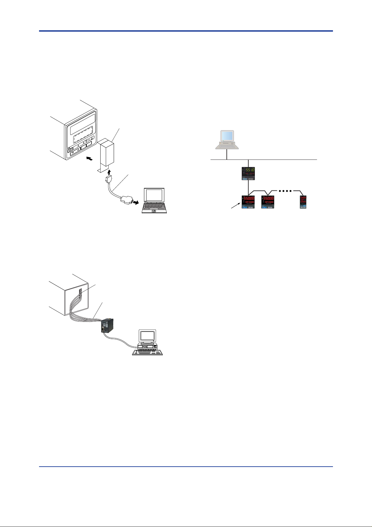
■Connection between the Controller and a Per-
sonal Computer
[Via Dedicated Adapter]
By attaching a dedicated adapter to the controller’s front
panel, users can upload and download parameter data to and
from a personal computer.
To communicate via the dedicated adapter:
Dedicated adapter
(optical/electrical signal converter)
Controller
Dedicated cable
Personal
computer
USB terminals
[Via RS-485 Communication Terminals]
Users can also upload and download parameter data to and
from a personal computer via the rear communication
terminals of the controller. This connection requires an RS232C/RS-485 converter (ML2).
To communicate via the communication terminals:
[Via Ethernet Communication Terminal]
The UT351-xA/UT551-xA to xD controllers can communicate with a personal computer via the Ethernet communication terminal. Connect a personal computer and a communicable network using a cable that meets the 10BASE-T/
100BASE-TX standards. Also, the UT351-xA/UT551-xA to
xD controllers and VJET converter can use the Ethernetserial gateway function to communicate with the GREEN
Series controllers equipped with the communication
functions via network. In this case, cross-connect the rear
communication terminals of the UT351-xA/UT551-xA to
xD/VJET and of the GREEN Series controllers.
PC
ETHERNET
10BASE-T/100BASE-TX cable
UT351-xA,
UT551-xA to xD
or VJET
Connect the RS485
rear communication
terminals.
GREEN Series controllers
RS485
Communication terminals
Shielded cables
Model ML2
RS-232C/RS-485
converter
Not available for UT551-xA to xD
and UT351-xA.
Personal
computer
All Rights Reserved. Copyright © 2000, Yokogawa Electric Corporation
GS 05G01B12-01E 8th Edition Nov.30,2006-00
Page 3

<<Contents>> <<Index>>
3
■Operating Environment
Personal Computer:
Windows 2000/XP-enabled IBM PC/AT compatible machine
Operating system: Windows 2000 (Professional)/XP
(Home Edition/Professional)
CPU: 300-MHz Pentium processor or superior is
recommended.
Main memory: 128 MB minimum is recommended.
Hard disk: Memory space required to store the tool’s
programs; 10 MB
Memory space required to store the parameter
data; 2 MB minimum
Memory space required to store the driver for
USB-Serial converter; 1 MB
CRT display: 800 ⫻ 600 pixels or superior
Smaller fonts should be used.
Should be capable of handling at least 256
colors.
USB communication port: One channel (COM1 to
COM16), with SeriesA connector, compliant
with USB Specification Rev1.1.
Network: 10BASE-T/100BASE-TX (required for
Ethernet communication)
CD-ROM drive: Required for installation.
Printer: Required for printing. Windows 2000/XP-
compatible A4-size printer
Dedicated Adapter
Communication method:
Controller side; optical, contactless, bidirec-
tional serial communication
Personal computer side; compliant with USB
Specification Rev1.1
Power supply: Supplied from USB bus power (no internal
battery)
Input rating; 4.4 to 5.25 V DC, 100 mA
(including a dedicated cable)
* No plug for external power source, no power switch
Ambient temperature range: 0 to 50°C
Ambient humidity range: 20 to 90% RH (no condensation)
Transport and storage conditions: -20 to 65°C, 10 to
90%RH (no condensation)
Dust- and water-proof construction: Not applied.
Standard: CE Marking (EMC only)
Dedicated Cable
Built-in USB-Serial converter
Personal computer side: USB SeriesA plug
Adapter side: RJ45 (8-pin) plug
Cable length: Approx. 2.7 m
■External Dimensions
Dedicated Adapter
3
Cable
36
45.5
96
Controller
96
(100)
Unit: mm
41
11
Dedicated Cable
107 350±102240±50
To adapter
Unit: mm
To PC (USB)
■Model and Suffix Codes
Model
LL100
Trademarks
• Windows 2000/XP are registered trademarks of Microsoft
• Pentium is a registered trademark of Intel Corporation,
• Ethernet is a registered trademark of XEROX Corporation,
• Other company and product names are trademarks or
Suffix
Description
code
PC-based Parameters Setting Tool
Model for use with IBM PC/AT compatible
-U10
machine (common to English and
Japanese version), USB connection
Corporation, USA.
USA.
USA.
registered trademarks of their respective holders.
3
96
2
■Packaged Contents
CD (2 disks):
LL100/USB converter driver software (1 disk)
User’s Manual (Reference) (CD version) (1 disk)
Dedicated adapter and dedicated cable:
For connecting a personal computer to optical
communication interface on the front of
controller (1 set)
All Rights Reserved. Copyright © 2000, Yokogawa Electric Corporation GS 05G01B12-01E 8th Edition Nov.30,2006-00
 Loading...