

Page 1

User ’s
Manual
AQ1300 Series
1G/10G ETHERNET
Multi Field Tester
IM AQ1300-01EN
6th Edition
Page 2

Thank you for purchasing the AQ1300 Series 1G/10G ETHERNET Multi Field Tester. This user’s
manual explains the features, operating procedures, and handling precautions of the AQ1300 Series.
To ensure correct use, please read this manual thoroughly before operation. Keep this manual in a
safe place for quick reference in the event that a question arises. This manual is one of five AQ1300
Series manuals. Please read all the manuals.
Manual Title Manual No. Description
AQ1300 Series 1G/10G ETHERNET
Multi Field Tester Operation Guide
AQ1300 Series 1G/10G ETHERNET
Multi Field Tester User’s Manual (included
in CD)
AQ1300 Series 1G/10G ETHERNET
Multi Field Tester Communication
Interface User’s Manual (included in CD)
AQ1300 MFT10GbE Setup Software
User’s Manual (included in CD)
AQ1300 Series Remote Control Software
User’s Manual (in CD)
IM AQ1300-02EN This guide focuses on the handling precautions,
basic operations, and specifications of the AQ1300
Series.
IM AQ1300-01EN This manual. It explains all the AQ1300 Series
features and how to use them.
IM AQ1300-17EN The manual explains the AQ1300 communication
interface features and instructions on how to use
them.
IM AQ1300-61EN This manual explains how to use a PC to create
AQ1300 Series setup files, display result files, and
generate CSV files.
IM AQ1300-63EN This manual explains how to remotely control the
AQ1300/AQ1301 from a PC.
Notes
• This manual (IM AQ1300-01EN 6th edition) applies to AQ1300 Series 1G/10G ETHERNET
Multi Field Testers with firmware version R1.10.01.001 and later.
If you are using an older version, you will not be able to use all the features described in this
manual.
Check the firmware version of your product on the product information screen. For information
on how to view the product information, see section 15.4. For information on how to update the
firmware, see section 15.5.
• The contents of this manual are subject to change without prior notice as a result of continuing
improvements to the instrument’s performance and functionality. The figures given in this manual
may differ from those that actually appear on your screen.
• Every effort has been made in the preparation of this manual to ensure the accuracy of its
contents. However, should you have any questions or find any errors, please contact your nearest
YOKOGAWA dealer.
• Copying or reproducing all or any part of the content of this manual without the permission of
YOKOGAWA is strictly prohibited.
Trademarks
• Microsoft, Windows, Windows XP, and Windows Vista are either registered trademarks or
trademarks of Microsoft Corporation in the United States and/or other countries.
• Adobe and Acrobat are either registered trademarks or trademarks of Adobe Systems Incorporated.
• In this manual, the ® and TM symbols do not accompany their respective registered trademark or
trademark names.
• Other company and product names are registered trademarks or trademarks of their respective
holders.
6th Edition: June 2014 (YMI)
All Rights Reserved, Copyright © 2009, Yokogawa Electric Corporation
All Rights Reserved, Copyright © 2010, Yokogawa Meters & Instruments Corporation
IM AQ1300-01EN
i
Page 3

Revisions
1st Edition: November 2009
2nd Edition: March 2010
3rd Edition October 2010
4th Edition June 2012
5th Edition March 2013
6th Edition June 2014
ii
IM AQ1300-01EN
Page 4

Conventions Used in This Manual
Notes
The notes and cautions in this manual are categorized using the following symbols.
Improper handling or use can lead to injury to the user or damage to the
instrument. This symbol appears on the instrument to indicate that the user must
refer to the user’s manual for special instructions. The same symbol appears in
the corresponding place in the user’s manual to identify those instructions. In the
user's manual, the symbol is used in conjunction with the word “WARNING” or
“CAUTION.”
WARNING
CAUTION
Calls attention to information that is important for proper operation of the
Note
Calls attention to actions or conditions that could cause serious or fatal injury to
the user, and precautions that can be taken to prevent such occurrences.
Calls attention to actions or conditions that could cause light injury to the user
or cause damage to the instrument or user’s data, and precautions that can be
taken to prevent such occurrences.
instrument.
Symbols and Conventions Used in Procedural Explanations
The contents of the procedural explanations are indicated using the following symbols.
Procedure
Explanation
Character Notations
Hard Key Names and Soft Key Names in Bold Characters
Indicate panel keys that are used in the procedure and soft keys and menu items that appear on the screen.
Carry out the procedure according to the step numbers. All procedures are
written under the assumption that you are starting operation at the beginning
of the procedure, so you may not need to carry out all the steps in a procedure
when you are changing the settings.
This section describes the setup items and the limitations regarding the
procedures. It may not give a detailed explanation of the feature. For a detailed
explanation of the feature, see chapter 1.
IM AQ1300-01EN
Unit
k Denotes 1000. Example: 12 kg, 100 kHz
iii
Page 5

Contents
Conventions Used in This Manual ................................................................................................... iii
Chapter 1 Features
1.1 Interaction between the Setup Software and the AQ1300 Series .................................... 1-1
1.2 Test Menu (Top Menu) ...................................................................................................... 1-2
1.3 Test Modes ....................................................................................................................... 1-3
1.4 Test Configurations ........................................................................................................... 1-4
1.5 Layer 1 Control ................................................................................................................. 1-7
1.6 Transmission Features ..................................................................................................... 1-9
1.7 Reception Features ........................................................................................................ 1-15
1.8 Statistics ......................................................................................................................... 1-19
1.9 Emulation ....................................................................................................................... 1-30
1.10 Ping and Traceroute Testing ........................................................................................... 1-35
1.11 Logging Statistics ........................................................................................................... 1-36
1.12 Simple Test Creation and Execution............................................................................... 1-37
1.13 Displaying Test Pass/Fail Results................................................................................... 1-38
1.14 File .................................................................................................................................. 1-39
1.15 Optical Power Measurement (AQ1300 Option) .............................................................. 1-40
1.16 RFC2544 Measurement (AQ1300 Option) ..................................................................... 1-41
1.17 VLAN Test....................................................................................................................... 1-48
1.18 Telnet Remote Control .................................................................................................... 1-49
1.19 E-OAM Test .................................................................................................................... 1-50
Chapter 2 Screen Explanations
2.1 Measurement Screens (Common Items) ......................................................................... 2-1
2.2 Measurement Screens (Test-mode-specific items) .......................................................... 2-6
Chapter 3 Common Operations
3.1 Key, Rotary Knob, and Arrow Key Operations.................................................................. 3-1
3.2 Entering Strings ................................................................................................................ 3-5
Chapter 4 Automatic Test Settings (Auto)
4.1 Selecting a Setup File ...................................................................................................... 4-1
4.2 Setting Up a Test .............................................................................................................. 4-4
4.3 Configuring Link and Address Settings ............................................................................ 4-5
4.4 Configuring Test Items .................................................................................................... 4-16
4.5 Configuring a Traffic Test ................................................................................................ 4-17
4.6 Configuring a Loopback Test .......................................................................................... 4-21
4.7 Configuring a QoS Test .................................................................................................. 4-22
4.8 Configuring a Ping Test .................................................................................................. 4-24
4.9 Configuring a BERT ........................................................................................................ 4-26
4.10 Displaying Pass/Fail Judgment Conditions .................................................................... 4-27
4.11 Configuring Options (Auto) ............................................................................................. 4-28
iv
IM AQ1300-01EN
Page 6

Contents
Chapter 5 Automatic (Remote Control) Test Settings (Auto(Remote))
5.1 Selecting a Setup File ...................................................................................................... 5-1
5.2 Setting Up a Test .............................................................................................................. 5-3
5.3 Configuring Link Settings ................................................................................................. 5-4
5.4 Configuring the Master Settings ....................................................................................... 5-6
5.5 Configuring the Slave Settings ....................................................................................... 5-13
5.6 Switching between the Master and Slave Settings ........................................................ 5-15
5.7 Controlling the Other Device Remotely .......................................................................... 5-16
Chapter 6 Manual Test Settings (Manual)
6.1 Selecting a Setup File ...................................................................................................... 6-1
6.2 Setting Up a Test .............................................................................................................. 6-2
6.3 Configuring Link and Address Settings ............................................................................ 6-3
6.4 Selecting a Test Mode .....................................................................................................6-11
6.5 Configuring a Traffic Test ................................................................................................ 6-12
6.6 Configuring a Loopback Test .......................................................................................... 6-29
6.7 Configuring a QoS Test .................................................................................................. 6-30
6.8 Configuring a Ping Test .................................................................................................. 6-43
6.9 Configuring a BERT ........................................................................................................ 6-45
6.10 Configuring the Statistics Log ......................................................................................... 6-50
6.11 Configuring Options (Manual) ........................................................................................ 6-52
Chapter 7 Measuring
7.1 Starting and Stopping Measurement ................................................................................ 7-1
7.2 Performing L1 Control ...................................................................................................... 7-8
7.3 Changing the Tx Rate..................................................................................................... 7-10
7.4 Inserting Errors ................................................................................................................7-11
7.5 Performing a Traceroute Test ......................................................................................... 7-12
7.6 Displaying Test Results .................................................................................................. 7-14
7.7 Comparing Transmission and Reception ....................................................................... 7-15
7.8 Customizing the Display ................................................................................................. 7-17
7.9 Displaying Detailed Statistics ......................................................................................... 7-19
7.10 Changing the Displayed Screen ..................................................................................... 7-21
7.11 Operating the Other Device ............................................................................................ 7-23
7.12 Switching between the Master and Slave Displays ........................................................ 7-24
7.13 Clearing the History ........................................................................................................ 7-25
7.14 Displaying the Header Information of Received Frames ................................................ 7-26
1
2
3
4
5
6
7
8
9
10
11
12
13
Chapter 8 Configuring RFC2544 Measurement Settings (AQ1300 Option)
8.1 Selecting a Setup File ...................................................................................................... 8-1
8.2 Setting Up a Test .............................................................................................................. 8-4
8.3 Configuring Link Address Settings ................................................................................... 8-5
8.4 Configuring Common RFC2544 Test Items .....................................................................8-11
8.5 Configuring Throughput Test Settings ............................................................................ 8-15
8.6 Configuring Latency Test Settings .................................................................................. 8-17
8.7 Configuring Frame Loss Rate Test Settings ................................................................... 8-19
8.8 Configuring Back to Back Test Settings.......................................................................... 8-21
8.9 Configuring Packet Jitter Test Settings ........................................................................... 8-22
8.10 Configuring RFC2544 Options ....................................................................................... 8-24
IM AQ1300-01EN
14
15
App
Index
v
Page 7

Contents
Chapter 9 Performing RFC2544 Measurements (AQ1300 Option)
9.1 Starting Measurement ...................................................................................................... 9-1
9.2 Displaying the Test Results .............................................................................................. 9-4
9.3 Displaying Throughput Test Results ................................................................................. 9-6
9.4 Displaying Latency Test Results ....................................................................................... 9-8
9.5 Displaying Frame Loss Rate Test Results ...................................................................... 9-10
9.6 Displaying Back to Back Test Results ............................................................................ 9-12
9.7 Displaying Packet Jitter Test Results.............................................................................. 9-13
9.8 Changing the Displayed Screen ..................................................................................... 9-15
Chapter 10 Optical Power Measurement (AQ1300 Option)
10.1 Pre-Measurement Calibration ........................................................................................ 10-1
10.2 Setting Optical Power Measurement Conditions and Holding the Display ..................... 10-2
Chapter 11 VLAN Test
11.1 Selecting a Setup File .....................................................................................................11-1
11.2 Configuring the Test Settings...........................................................................................11-3
11.3 Configuring Link Address Settings ..................................................................................11-4
11.4 Configuring the Tx Settings .............................................................................................11-9
11.5 Configuring the VLAN ID Tx Settings ............................................................................11-10
11.6 Configuring the VLAN ID Rx Settings ............................................................................11-14
11.7 Starting and Stopping Measurement .............................................................................11-17
11.8 Switching Screens and Saving Measured Results ........................................................11-20
Chapter 12 E-OAM Test
12.1 Selecting a Setup File ..................................................................................................... 12-1
12.2 Configuring the Test Settings.......................................................................................... 12-3
12.3 Setting the Test Mode ..................................................................................................... 12-4
12.4 Configuring Link Address Settings ................................................................................. 12-5
12.5 Configuring the LB Test .................................................................................................12-11
12.6 Configuring the CC Test ............................................................................................... 12-12
12.7 Setting Options (E-OAM) .............................................................................................. 12-16
12.8 Starting and Stopping an LB Test ................................................................................. 12-17
12.9 Starting and Stopping a CC Test .................................................................................. 12-19
12.10 Executing an LT and Multicast LB ................................................................................ 12-22
Chapter 13 File Operation
13.1 Connecting a USB Storage Medium to the USB Port .................................................... 13-1
13.2 Saving and Loading Data ............................................................................................... 13-2
13.3 Deleting and Copying Files ............................................................................................ 13-6
13.4 Changing File Names ..................................................................................................... 13-8
12.5 Creating Directories ........................................................................................................ 13-9
13.6 Deleting and Copying Directories ................................................................................. 13-10
13.7 Specifying the Items That Are Displayed in the File List................................................13-11
vi
IM AQ1300-01EN
Page 8

Contents
Chapter 14 Other Operations
14.1 Configuring the Language, Beep, and USB Function .................................................... 14-1
14.2 Setting the Date and Time .............................................................................................. 14-2
14.3 Configuring Power Save Settings ................................................................................... 14-3
14.4 Configuring Network Settings ......................................................................................... 14-4
14.5 Resetting the AQ1300 Series to Its Factory Default Settings ......................................... 14-6
14.6 Setting the Top Menu Type ............................................................................................. 14-7
14.7 Using the Utility Menu .................................................................................................... 14-9
Appendix
Appendix 1 Data File Format ................................................................................................App-1
Index
1
2
3
4
5
6
7
8
9
10
11
12
13
14
15
App
IM AQ1300-01EN
Index
vii
Page 9
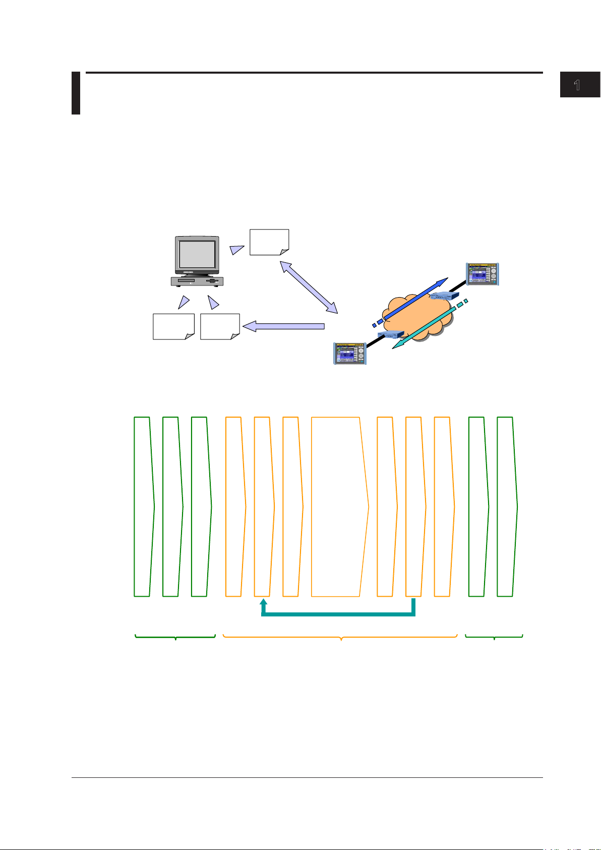
Setup Software
Report output
• You can also change the parameters based on the loaded settings.
Operation Example (for Auto Mode)
operations
Setup software
operations
Chapter 1 Features
1.1 Interaction between the Setup Software and the AQ1300 Series
Create a test scenario with the setup software PC application, and then save the scenario to a setup
file. Upload the saved setup file to the AQ1300 Series (AQ1300 and AQ1301), and then use the test
scenario to perform a test. The test results are saved to a result file. Use the PC to download the result
file, and then use the setup software to print a report.
You can upload and download files using the Ethernet (FTP), USB storage media, and USB memory.
(Windows APP)
Setup
PC
Report
Result
file
file
Setting
configuration
Result display
AQ1300 Series
Upload/
download
Download
AQ1300 Series
• After loading a setup file, begin measurement simply by pressing START.
1
Features
Create a test scenario.
Save a measurement setup file.
Transfer a measurement setup file.
Setup software
Select a measurement setup file.
(These items can be executed in order automatically.)
Change the test parameters (if necessary).
Select a test item.
AQ1300 Series operations
• Ping test
• BERT
• QoS test
• Traffic test
Judge the measurement results.
Automatically save the measurement results.
End testing.
Send the report of the measurement results.
Create a report of the measurement results.
For details about the setup software, see the Setup Software User’s Manual, IM AQ1300-61EN.
IM AQ1300-01EN
1-1
Page 10

1.2 Test Menu (Top Menu)
Auto
Select Auto to perform automatic testing on a device according to the test items in the selected setup
file. You can execute up to eight test items in order or at the same time. You can display pass/fail
results for each test and automatically save the measurement results to a file.
You can configure setup files and test items using the setup software, which runs on Windows PC.
Auto(Remote)
Select Auto(Remote) to use a master device to perform automatic testing of a remote slave device
according to the test items in the selected setup file. You can execute up to eight test items in
order or at the same time. You can display pass/fail results for each test and automatically save the
measurement results to a file.
Because the master device controls the slave device remotely, a single person can perform the tests.
The slave device can be configured remotely, and its measurements can be collected by the master
device.
You can configure setup files and test items using the setup software, which runs on Windows PC.
Manual
Select Manual to perform manual testing on a device using a single test item in the selected setup file.
You can generate traffic and perform analysis in greater detail than you can when you select Auto or
Auto(Remote).
You can configure setup files and test items using the setup software, which runs on Windows PC.
OPM (AQ1300 Option)
Select OPM to measure optical input power using the optical power meter.
RFC2544 (AQ1300 Option)
An automated test function in conformity with RFC2544, the standard benchmarking methodology for
a performance examination of Ethernet service and network systems.
• Throughput: Maximum frame transfer rate without frame loss.
• Latency: Delay time of a frame
• Frame loss rate: Incidence rate of frame loss with excess traffic.
• Back-to back: Maximum burst value not causing a frame loss.
• Packet jitter: Variation of latency
VLAN Test
The VLAN Test is used to check the VLAN trunk configuration. You can compare the VLAN ID list that
you plan to receive with the actual received VLAN ID list. The VLAN Test consists of transmission,
reception, analysis, and result display and storage features.
E-OAM Test
Ethernet Operation, Administration and Maintenance (hereafter referred to as E-OAM) tests can be
performed in compliance with the ITU-T Y.1731 Recommendation and IEEE802.1ag Standard.
This is supported in firmware version R1.10.01.001 and later.
• CC (continuity check) test: Connection check between network devices
• LB (loop back) test: Response check between network devices
• LT (link trace): Link check between network devices
1-2
System
Select System to configure the AQ1300 Series system settings.
Language, Beep, USB Function, Date & Time Set, Power Save mode, Network Setup, Factory Setting,
Product Info. display, Selftest, Version Up
IM AQ1300-01EN
Page 11

1.3 Test Modes
Traffic Test Mode
In this mode, you generate traffic and measure the network throughput by defining a single Tx frame
and specifying the frame length and Tx rate.
When the other device is in Loopback Test mode, you can perform latency measurement.
Loopback Test Mode
In this mode, the source and target addresses of received frames are reversed, and the frames are
sent back to their source. The AQ1300 Series takes statistics of the received frames.
Testing is performed with the other device set to Traffic Test, QoS Test, or BERT mode.
QoS Test Mode
In this mode, you can generate QoS measurement traffic and measure the network QoS performance
by defining a Tx frame with up to eight channels of QoS parameters and specifying the frame length
and Tx rate. The AQ1300 Series takes statistics of each individual QoS channel.
When the device under test is in Loopback Test mode, you can perform latency measurement on
individual QoS channels.
PING Test Mode
In this mode, you can verify layer 3 connectivity. You can ping a single host at intervals of 1 s or less (1
ms minimum).
You can also use traceroute testing to check the route to the target (the other device).
1
Features
BERT Mode
In this mode, bit error rate testing is performed. The AQ1300 Series inserts a pseudo-random pattern
(PN15) into the payload of the Tx frame and checks whether or not bit errors are occurring between
itself and the other device.
The other device must be set to BERT mode or Loopback Test mode.
IM AQ1300-01EN
1-3
Page 12
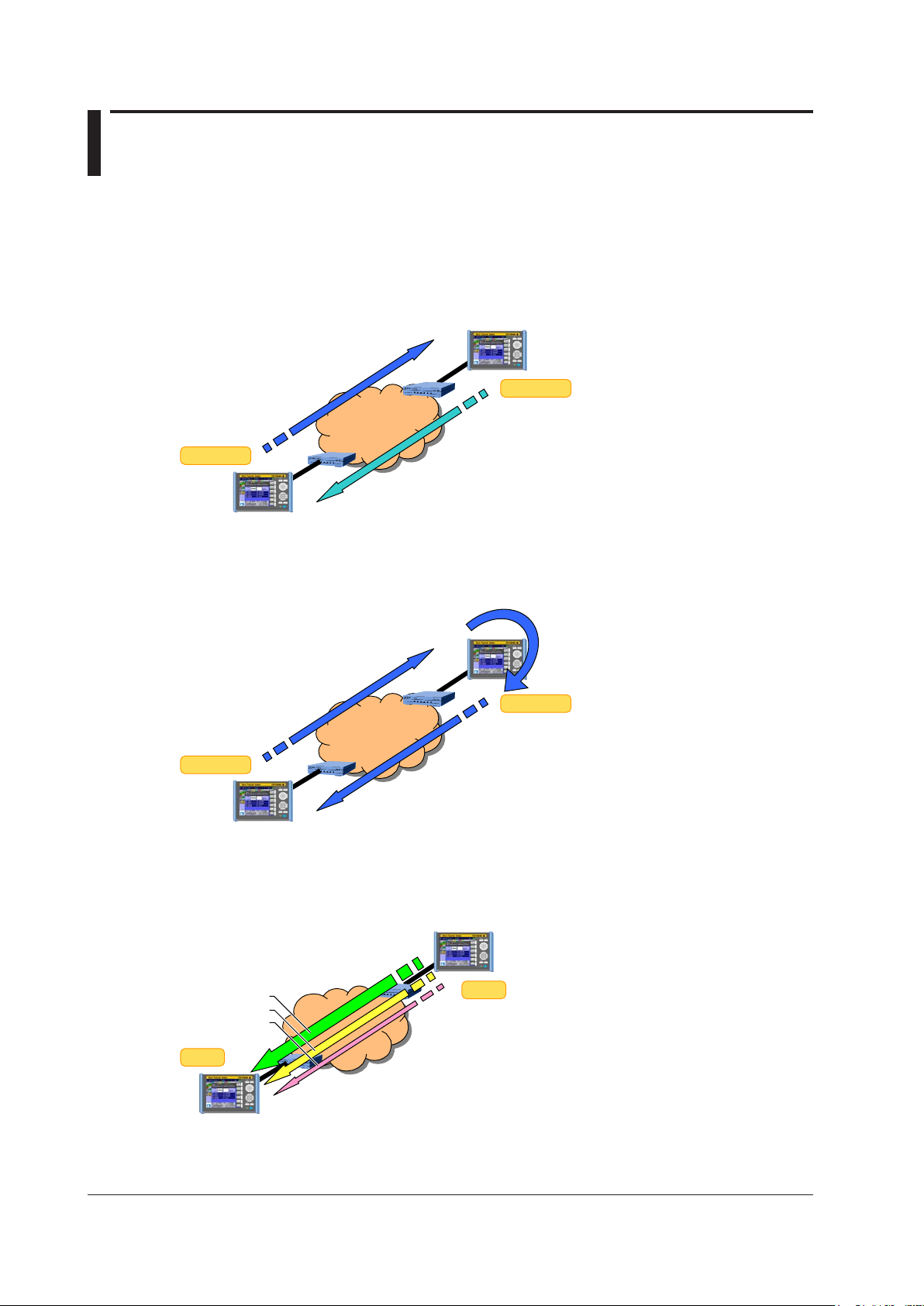
1.4 Test Configurations
Other device
• TCP/UDP Dst/Src port switching
Up to 8CH when the Test menu is set to Manual
Other device
The test configurations in which the AQ1300 Series can be used are listed below.
Two-Way Traffic Test
The AQ1300 Series and the other device measure the network throughput by sending and receiving
traffic between themselves.
Network
Traffic
Loopback Traffic Test (Latency measurement)
The other device is set to Loopback Test mode so that the AQ1300 Series receives the traffic that it
sends, and the AQ1300 Series measures the network round-trip latency.
Traffic
Other device
Network
Traffic
Loopback
• MAC address DA/SA switching
• IP address DA/SA switching
QoS Test
The AQ1300 Series measures the network QoS performance by sending and receiving up to eight
channels of QoS traffic.
Network
QoS CH1
QoS
CH2
CH3
QoS traffic
Up to 4CH when the Test menu is set to Auto
QoS
1-4
IM AQ1300-01EN
Page 13
Other device
Other device
Other device
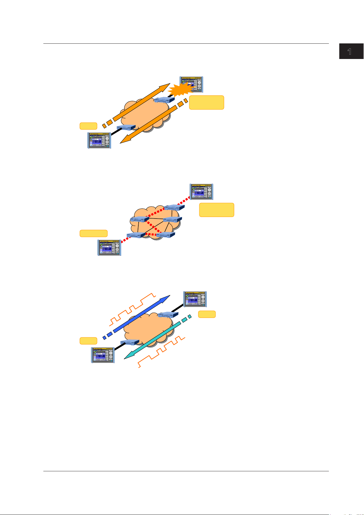
1.4 Test Configurations
Ping Test
The AQ1300 Series verifies layer 3 connectivity.
Ping traffic generation
Interval: 1 ms to 1 s
PING
Network
Reply
PING
emulation
Ping reply
emulation
1
Features
Traceroute Test
You can also use traceroute testing to check the route to the target (the other device).
Network
ICMP
emulation
Traceroute
BERT Test
The AQ1300 Series performs a bit error rate test.
PN pattern
BERT
BERT
Network
PN pattern
IM AQ1300-01EN
1-5
Page 14
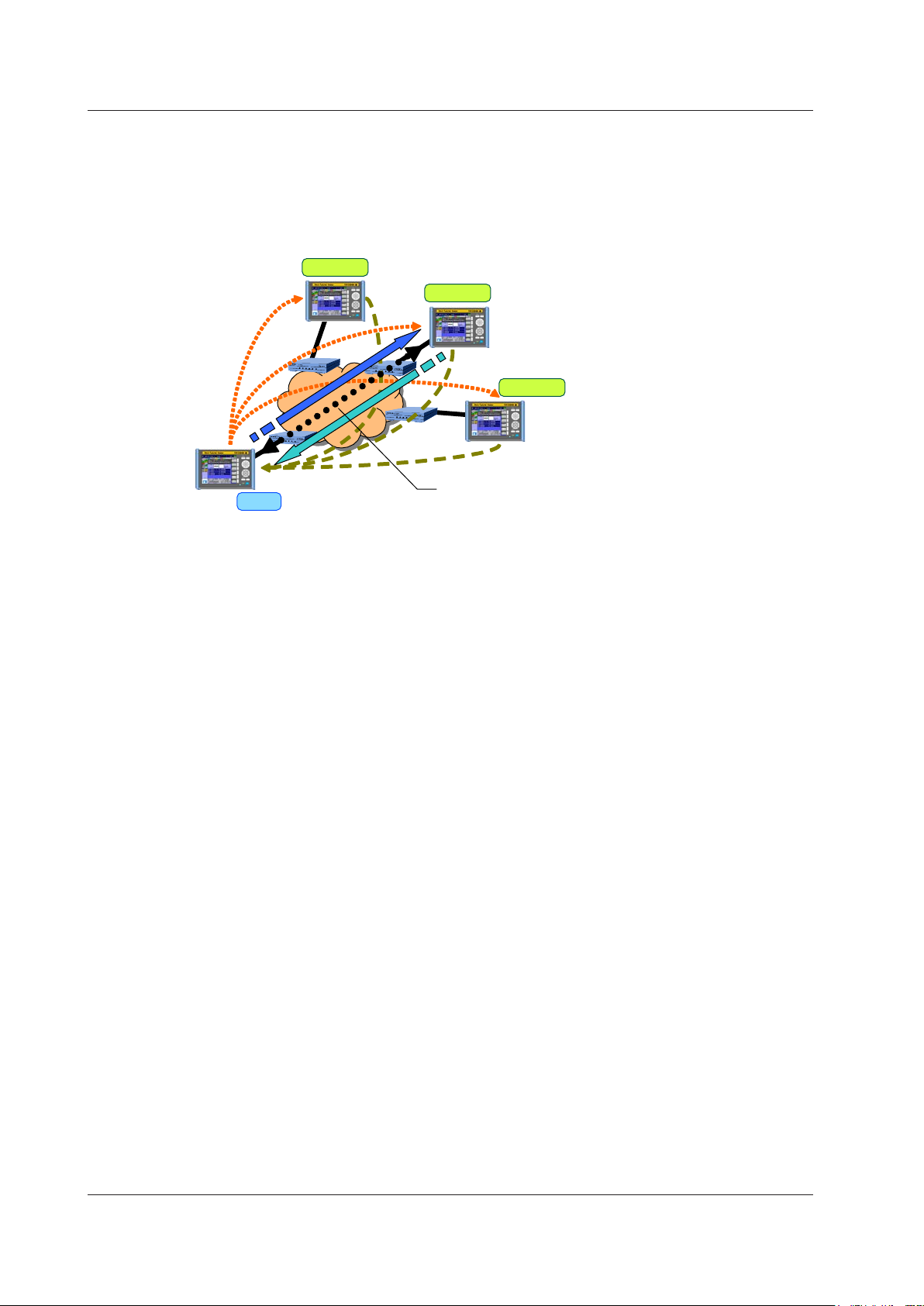
The master can control the slaves remotely through the measured
• Searching for slaves: The AQ1300 can search for up to 64 slaves.
• Controlling slaves: The AQ1300 can only control one slave at a time.
Just bring the slave device, connect the cables, and turn it on.
Control through dedicated remote commands
1.4 Test Configurations
Inband Remote
This is the test configuration for an Auto(Remote) test.
You can use dedicated remote commands to perform testing on the slave, change settings, and
acquire measurement results. Because the slave device can be controlled remotely, a single person
can perform this test.
Slave 1
Slave 2
Search
Master
Search response
• Testing can be performed on the slave.
Slave 3
connection.
1-6
IM AQ1300-01EN
Page 15
1.5 Layer 1 Control
Tx Clock Master/Slave Synchronization
When Manual has been selected in the Test menu and the interface is XFP or SFP, you can select the
Tx clock source.
Tx Clock Source
Internal CLK: The internal clock is used.
Received CLK: The AQ1300 Series synchronizes with the Rx line signal.
Rx Clock Measurement
When the interface is XFP, SFP, or RJ-45 100BASE-TX, you can measure the frequency deviation of
the Rx clock.
Link State Measurement Result Display
Linkdown “---” is displayed.
Linkup The frequency deviation of the Rx clock is displayed [ppm].
When the interface is RJ-45, the AQ1300 Series cannot measure the frequency deviation of the Rx
clock for 1000BASE-T or 10BASE-T connections. To measure the frequency deviation of the Rx clock
through the RJ-45 interface, use a 100BASE-TX connection.
LF and RF Transmission and Detection
When the interface is XFP, because the AQ1300 Series supports the notification of physical layer
failures through LFS (link fault signaling), it can transmit and detect LF (local fault) and RF (remote
fault) signals.
The AQ1300 Series can transmit LF and RF signals consecutively (start/stop).
Also, when Manual has been selected in the Test menu, the AQ1300 Series can automatically send an
RF signal upon linkdown detection or LF signal reception.
1
Features
RxLF (Local Fault reception)
Detection: Four or more sequence columns that indicate LF at an interval less than 128 columns.
Sequence columns that indicate RF must not be received during this period.
Clear: When sequence columns that include LFs are not received 128 times.
RxRF (Remote Fault reception)
Detection: Four or more sequence columns that indicate RF at an interval less than 128 columns.
Sequence columns that indicate LF must not be received during this period.
Clear: When sequence columns that include RFs are not received 128 times.
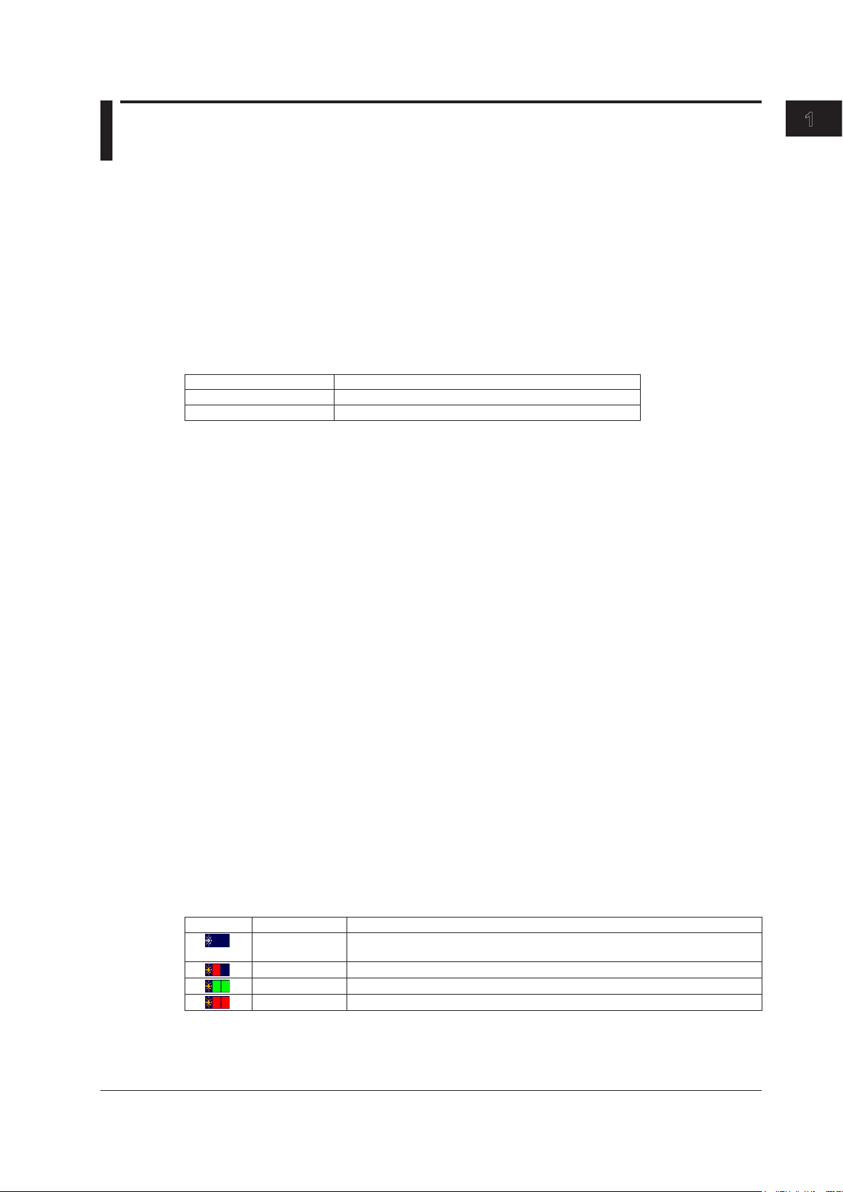
Simple Optical Power Monitor
When the interface is XFP or SFP, the AQ1300 Series can monitor the received optical power level
and indicate it using three levels.
Indication Colors Description
Black and black When the RJ-45 interface is being used or when the XFP or SFP interface is
being used and the interface module is not installed
Red and black When the level of received light is too low
Green and green When the level of received light is appropriate
Red and red When the level of received light is too high
IM AQ1300-01EN
1-7
Page 16

1.5 Layer 1 Control
Turning the Optical Output Off and On
When the interface is XFP or SFP, you can turn the optical output (laser) off and on.
You can force the link of the device under test down or up.
Linkdown Transmission Continuation
When Manual has been selected in the Test menu and the interface is XFP, you can choose to
continue or stop transmission during linkdown detection.
Sync Loss Detection of 66 Bits Blocks
When the interface is XFP, the AQ1300 Series detects the condition when the signal reception
changes from a block sync (block lock) state of 66 bits blocks to a loss of sync (block lock loss) state
as defined in IEEE802.3. When a sync loss of 66 bits blocks is detected, the link is disconnected. This
feature is supported in firmware version (FW Ver.) R1.08.01.001 and later.
66B Sync Error Detection
When the interface is XFP, the AQ1300 Series detects 66 bits blocks whose sync header (2 bits) is
except 00 or 11 when signal reception is in a sync (block lock) state as defined in IEEE802.3.
This feature is supported in firmware version (FW Ver.) R1.08.01.001 and later.
66B Sync hi-ber Detection/Clear
When the interface is XFP, the AQ1300 Series detects and clears 66B Sync hi-ber on the basis of the
following conditions when signal reception is in a sync (block lock) state as defined in IEEE802.3.
This feature is supported in firmware version (FW Ver.) R1.08.01.001 and later.
Detection: When16ormoresyncheaders(2bits)setto00or11aredetectedina125μswindow
Clear: When less than 16 sync headers (2 bits) that are not set to 01 or 10 are detected in a 125
when signal reception is in a sync (block lock) state as defined in IEEE802.3.
µs window when signal reception is in a sync (block lock) state as defined in IEEE802.3.
Note
IEEE802.3 defines the sync (block lock) state of 66 bits blocks as follows:
Detection: When 64 consecutive sync headers (2 bits) set to 01 or 10 are received correctly.
Clear: When 16 sync headers (2 bits) that are not set to 01 or 10 are detected within 64 sync headers in a
sync (block lock) state.
Link Setting Acquisition
If the interface is SFP(GbE) or RJ-45, this feature is used to check the link settings of the DUT (the
device on the user side). You can acquire and display link setting information of the other device
connected to the AQ1300 Series or the DUT connected to the AQ1300 Series on the slave side as well
as the status of the differences in the negotiation settings. In addition, you can check the UTP cable
condition and display the results.
1-8
IM AQ1300-01EN
Page 17
1.6 Transmission Features
• • • • •
Frame IFG
Tx rate
• • • • •
Tx rate
Interval
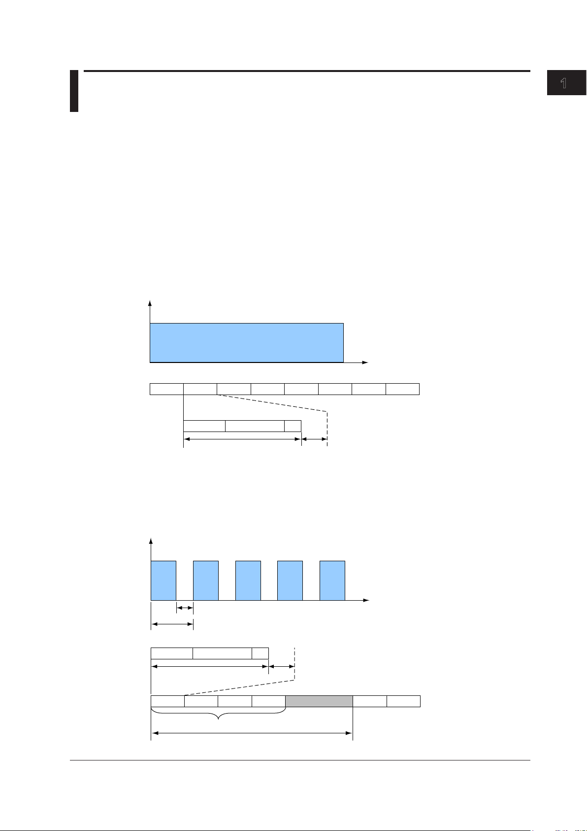
Transmission Load Configuration
When the test mode is Traffic Test, QoS Test, or BERT, you can set the transmission load by setting
the Tx rate and the Tx mode.
When the mode is Traffic Test or BERT, you can define a single frame. In QoS test mode, you can
define up to eight frames and assign them to the various transmission channels.
Tx Rate Settings
Traffic Format
When Manual has been selected in the Test menu, you can select a traffic format.
Constant
When the traffic format is Constant, frames are sent continuously at a constant interval. You can
change the interframe gap (IFG) by changing the Tx rate.
1
Features
Frame
Burst
When the traffic format is Burst, frames are transmitted in bursts: frame transmission starts and
stops repeatedly at a specified interval. You can change the interframe gap (IFG) by changing the
Tx rate. You can specify the number of Tx frames in the burst interval by setting Burst Number, and
you can specify the interval of repetition by setting Interval.
Interval
Preamble Data FCS
Time
Frame Frame Frame Frame Frame Frame Frame
Preamble Data FCS
Time
Idle
IM AQ1300-01EN
Frame IFG
Frame
Frame Frame Frame Idle Frame Frame
Number of burst frames
1-9
Page 18

1.6 Transmission Features
If the burst transmission interval determined by the value you set for Burst Number is greater than
the value you set for Interval, the AQ1300 Series will transmit frames at a constant rate without any
idle condition.
Tx Rate
When the Mode is Traffic Test or BERT
When Manual has been selected in the Test menu, you can set the Tx rate as a percentage or in
units of bits or fps. You can only set values that exceed 100% in units of bits. When Test Interface
is set to SFP(FE), you cannot set values that exceed 100%.
You can only set values as percentages when Auto or Auto(Remote) has been selected in the
Test menu.
Note
When the you set the Tx rate in bits, specify the number of bits in the IFG.
In QoS Test Mode
Regardless of the Test menu, you can only set the Tx rate as a percentage.
Tx Mode Settings
Continuous
In this mode, frames are transmitted continuously. After you start transmission, it continues until you
stop it.
Frames
In this mode, a specified number of frames is transmitted. After you start transmission, the specified
number of frames is sent, and then transmission is stopped automatically.
Tx Time
In this mode, frames are transmitted for a specified period of time. After you start transmission, it
continues for the specified period of time and is then stopped automatically.
1-10
IM AQ1300-01EN
Page 19
1.6 Transmission Features
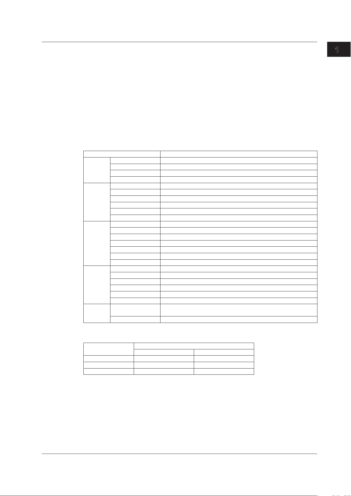
Tx Frame Definition
For the Tx frame definition, in addition to basic frame editing, you can also set the payload, variable
field setting, error addition, etc.
Frame Editing
When Manual has been selected in the Test menu, you can edit the following frames.
• When the test layer is L2: MAC+TYPE
• When the test layer is L3-IPv4: MAC+TYPE+IPv4
MAC+TYPE+IPv4+UDP
• When the test layer is L3-IPv6: MAC+TYPE+IPv6
MAC+TYPE+IPv6+UDP
The fields and settings that you can edit are listed below.
Field Setting
MAC Destination Manual, the same as Destination Setting
Address value format **-**-**-**-**-**
Source Manual, the same as Source Setting
Address value format **-**-**-**-**-**
VLAN Flag use Used, Source Address
VLAN stacks None, 1, 2
VLAN-[1-2]TPID 0x0000-0xFFFF
VLAN-[1-2]CoS 0-7
VLAN-[1-2]CFI 0-1
VLAN-[1-2]VLANID 0-4095
IPv4 Destination address Manual, the same as Destination Setting
Address value format ***.***.***.***
Source address Manual, the same as Source Setting
Address value format ***.***.***.***
ToS/DS(DSCP) Manual, IPv4-ToS, IPv4-DSCP
Service type value 0x00-0xFF (manual), 0-7 (IPv4-ToS), 0-63 (IPv4-DSCP)
Protocol 0-255 (when Frame Structure is MAC+TYPE+IPv4)
IPv6 Destination address Manual, the same as Destination Setting
Address value format ****:****:****:****:****:****:****:****
Source address Manual, the same as Source Setting
Address value format ****:****:****:****:****:****:****:****
ToS/DS(DSCP) 0x00-0xFF (manual), 0-7 (IPv6-TrafficClass), 0-63 (IPv6-DSCP)
NextHeader 0-255 (when Frame Structure is MAC+TYPE+IPv6)
UDP Destination port
number
Source port number 0 to 65535
0 to 65535
1
Features
IM AQ1300-01EN
When Auto or Auto(Remote) has been selected in the Test menu, the frame structures are fixed as
indicated below, and frames cannot be edited.
Test Layer Add UDP to Tx Frame
OFF ON
L2 MAC+TYPE —
L3-IPv4 MAC+TYPE+IPv4 MAC+TYPE+IPv4+UDP
L3-IPv6 MAC+TYPE+IPv6 MAC+TYPE+IPv6+UDP
1-11
Page 20
1.6 Transmission Features
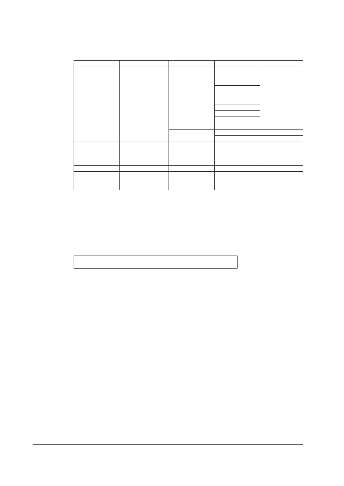
You can use the setup software to create the following frames for manual testing. For details see
the Setup Software User’s Manual, IM AQ1300-61EN.
L2 Protocol Type L2/L3 Tags L3 Protocol Type L4 Protocol Type Notes
DIX/IEEE802.3 Mac in
Pause Mac in
ARP — —
ECP EoE VLAN Tag — —
Custom (with MAC) — — —
Custom (without
MAC)
Payload Settings
User-Defined Data
You can use the setup software to attach a specified data sequence to the payload areas of the
various protocols. You can enter data sequences into payload areas of up to 256 bytes that include
the protocol headers. A fill pattern is inserted after the user-defined data.
IPv4 UDP IPv4 multicast is
Mac (IEEE802.1ah/
EoE, B-Tag)
VLAN Tag (4 stacks)
MPLS/EoMPLS
(4 stacks)
Mac (IEEE802.1ah/
EoE, B-Tag)
VLAN Tag (4 stacks)
— — —
IPv6 UDP
IPX —
E-OAM ITU-T
— —
TCP
IGMP
ICMP
TCP
IGMP
ICMP
ICMPv6
IEEE
supported.
Fill Pattern
You can insert a fill pattern into the payload areas of the various protocols.
AQ1300 Series ALL0, ALL1, 0/1 alt., Random, Manual (4 bytes)
Setup software Random, manual (4 bytes)
Variable Field
You can change the specified field when Manual has been selected in the Test menu and the test
mode is Traffic Test. There are two methods for changing a field: field specification, in which you
select a field directly, and offset specification, in which you set the offset, bit offset, and variable bit
width manually.
• Variable fields: 1
• Variable mode: Increment/random
• Variable size: Maximum width of 32 bits
Variable Frame Length
You can change the frame length when Manual has been selected in the Test menu and the test
mode is Traffic Test, QoS Test, or BERT. You can change a single frame when the mode is Traffic
Test or BERT. In QoS Test mode, you can change field lengths by channel.
• Variable mode: Increment/decrement/random
• Variable range: 64 to 9999 bytes
When Test Interface is set to SFP(FE), the sending and receiving of frames that exceed 2048 bytes
in length is outside of the AQ1300 Series guaranteed operating range.
Automatic Checksum Calculation
This feature guarantees the L3 header checksum when Manual has been selected in the Test
menu, field variation is enabled, and the variable field has been set to a field within the L3 header
checksum (IPv4 header) computation range.
1-12
IM AQ1300-01EN
Page 21
16 bytes 4 bytes8 bytes Arbitrary
1.6 Transmission Features
Test Tags
When you are using two AQ1300 Series in a two-way or loopback test configuration, you can attach
test tags for analysis to the Tx frames.
Test tags are inserted immediately before the Tx frame FCS.
Test tags can be inserted when the test mode is Traffic Test or QoS Test.
When Auto or Auto(Remote) has been selected in the Test menu, test tags are always inserted.
When Manual has been selected in the Test menu, you can select whether or not to insert test tags.
Preamble Test tags FCSData
Inserted Data
The following data is inserted into test tags.
Data Type Description
Test ID The IDs of the AQ1300 Series and the test item
Additional test data For status notification and exchanging test setup information
Frame ID The frame (QoS channel) number
Timestamp Latency measurement data is inserted here.
Sequence number A sequence number is inserted here.
Payload check CRC A CRC for the payload
Tag identifier A fixed identifier that indicates that the data is a tag.
Tag length Tag field length in units of 2 bytes (for expansion)
Timestamp
The timestamp (time data) is inserted into a (32-bit) field in the test tag. If the other device is in
Loopback Test mode, you can use the timestamp to measure the latency.
1
Features
Sequence Number
By inserting a sequence number into a (32-bit) field in a test tag and then sending the frame, the
AQ1300 Series can check for sequence errors between itself and the other device.
When the test mode is Traffic Test, the same sequence number is inserted for all ports. When the
test mode is QoS test, sequence numbers are inserted separately for each channel.
Payload Check CRC
By computing a (16-bit) CRC of the Tx frame payload, inserting the result into a test tag field, and
then sending the frame, the AQ1300 Series can check for payload errors between itself and the
other device.
PN Pattern
By inserting a pseudo-random pattern (PN15) into the fill pattern data area of a Tx frame payload
and then sending the Tx frame to the other device, the AQ1300 Series can perform a BER
measurement to check for device errors.
Error Addition
The AQ1300 Series can add the following errors to the frames that it sends.
CRC errors, symbol errors, sequence errors, payload errors, bit errors, undersize errors,
*
errors
* Set the Tx frame length.
*
oversize
IM AQ1300-01EN
1-13
Page 22

1.6 Transmission Features
Transmitting by QoS Channel
When Manual has been selected in the Test menu and the test mode is QoS test, you can specify
different frames, frame lengths, and transfer rates for each channel and send the frames separately.
When Auto or Auto(Remote) has been selected in the Test menu and the test mode is QoS test, you
can specify different QoS values, frame lengths, and transfer rates for each channel and send the
frames separately.
When Manual has been selected in the Test menu, you can select up to eight QoS channels; when
Auto or Auto(Remote) has been selected in the Test menu, you can select up to four.
1-14
IM AQ1300-01EN
Page 23

1.7 Reception Features
Base Filter
You can use the base filter to specify the conditions for selecting the received frames to take statistics
from.
You can set the base filter when Manual has been selected in the Test menu and the test mode is
Traffic Test, QoS Test, or BERT.
There are two filter types that you can choose from: field filtering, in which you select the field of the
protocol that you want take statistics of, and offset filtering, in which you set the filter location and
pattern.
There are two base filters. You can combine them and set whether to take the statistics of frames that
pass or do not pass through them.
QoS Channel Measurement
When Manual has been selected in the Test menu, you can measure up to eight QoS channels (classes)
separately; when Auto or Auto(Remote) has been selected in the Test menu, you can measure up to
four. By taking statistics for different flows, you can evaluate the priority control of a network device.
The QoS filter operates on the frames that pass through the base filters.
You can use the QoS filter when Manual has been selected in the Test menu and the test mode is QoS
Test.
There are two filter types that you can choose from: field filtering, in which you select the field of the
protocol that you want take statistics of, and offset filtering, in which you set the filter location and
pattern.
There are two QoS filters, and the AQ1300 Series takes the statistics of the frames that pass through
them.
1
Features
Latency Measurement
If you set the other device to Loopback Test mode, the AQ1300 Series can insert a timestamp in a Tx
frame and measure the latency by determining the difference between the timestamp and the time that
the frame comes back.
Gap Measurement
The AQ1300 Series measures the maximum, minimum, and average gaps (IFGs) between packets.
The values are displayed both in µs and bits.
Note
Frames whose length is between 48 and 9999 bytes can be received. Frames whose length exceeds 9999
bytes are detected as oversized frames.
When Test Interface is set to SFP(FE), frames whose length is between 48 and 2048 bytes are guaranteed
to be received.
IM AQ1300-01EN
1-15
Page 24
Duplicate Packet: 0
Duplicate Packet: 0
1.7 Reception Features
Sequence Measurement
The AQ1300 Series monitors the sequence numbers inserted in frames and takes sequence error
statistics for loss packets, maximum burst loss, reorder packets, and duplicate packets.
When the test mode is Traffic Test, all the ports are measured together. When the test mode is QoS
test, the channels are measured separately.
Detected Sequence Errors
Detected Error Type Error Description
Loss Packet The total number of lost frames
Max Burst Loss The maximum number of consecutive frames that have been lost
Reorder Packet The total number of frames that have been received out of the order that they
Duplicate Packet The number of received frames that have been received again
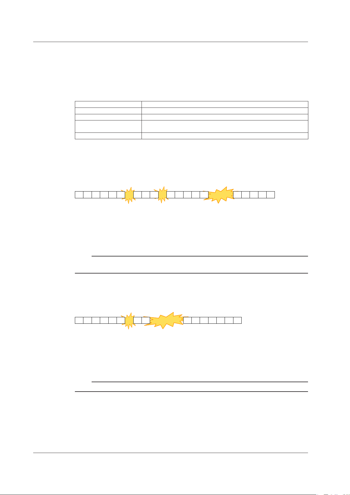
Sequence Error Detection Examples
Loss Packet
Frames that were sent but not received are counted as loss packets. The Loss Packet number
represents the total number of loss packets.
1 2 3 4 5 6 8 9 10 12 13 14 15 16 20 21 22 23 24
were sent in
Loss Packet: 5
Max Burst Loss: 3
Reorder Packet: 0
Note
• Burst loss packets are also counted as loss packets.
• Reorder packets are not counted as loss packets.
Max Burst Loss
Consecutive frames that the AQ1300 Series is unable to receive are counted as burst loss packets.
The Max Burst Loss number represents the maximum burst loss value.
1 2 3 4 5 6 8 9 14 15 16 20
Loss Packet: 5
Max Burst Loss: 4
Reorder Packet: 0
Loss
1
Loss Burst loss
1 4
Loss
1
Burst loss
3
17 18 19
1-16
Note
Reorder packets do not affect the measurement of the maximum burst loss.
IM AQ1300-01EN
Page 25
Duplicate Packet: 0
Duplicate Packet: 1
Duplicate Packet: 3
Duplicate Packet: 1
Consecutive reorder packet
1.7 Reception Features
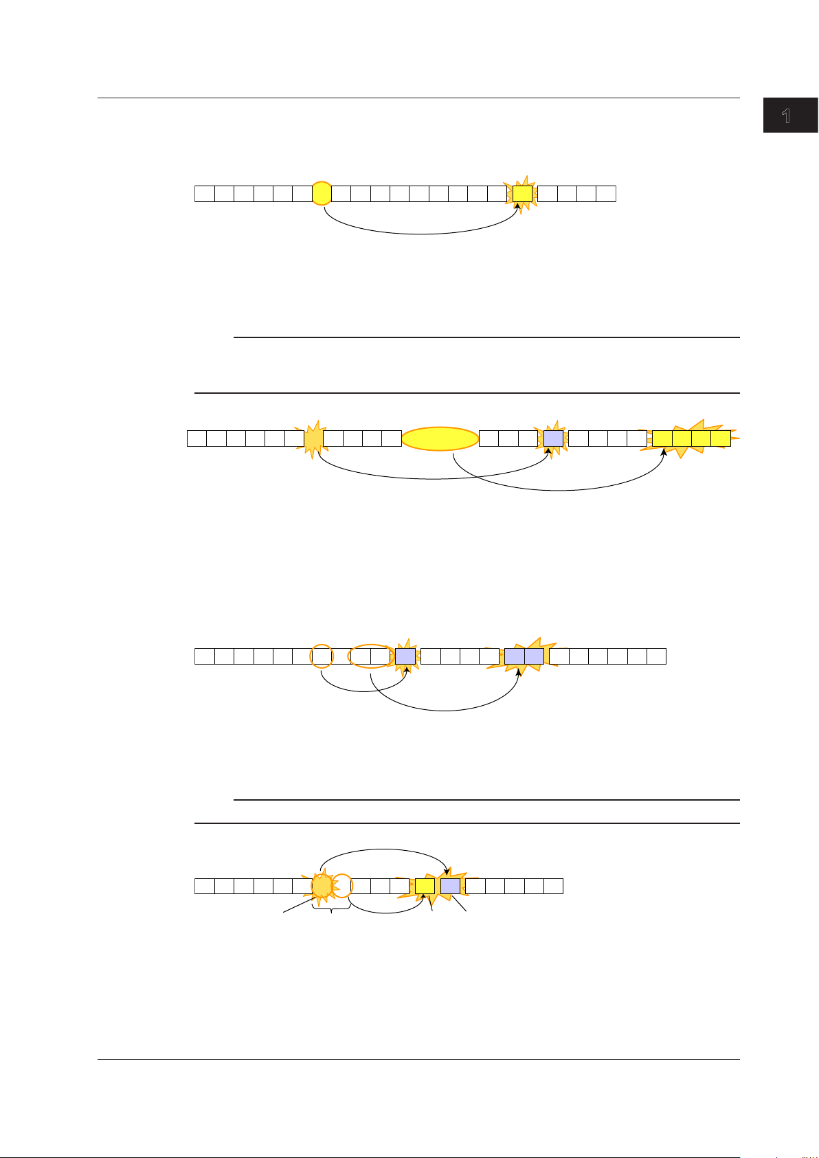
Reorder Packet
Frames that are received out of the order that they were sent in are counted as reorder packets.
The Reorder Packet number represents the total number of reorder packets.
1 2 3 4 5 6 8 9 10 12 13 14 15 16 20
Loss Packet: 0
Max Burst Loss: 0
Reorder Packet: 1
Note
• Reorder packets are detected from the previous loss packet or burst loss packet area.
• Reordered frames that are from two or more losses or burst loss areas before are counted as duplicate
packets.
1 2 3 4 5 6 8 9 10 12 13 14 1516 20
Loss Packet: 1
Max Burst Loss: 1
Reorder Packet: 4
Loss
1
18 1917711
Wrong order
18 1917 711 21 22
Duplicate
1
1
Features
Wrong order
4
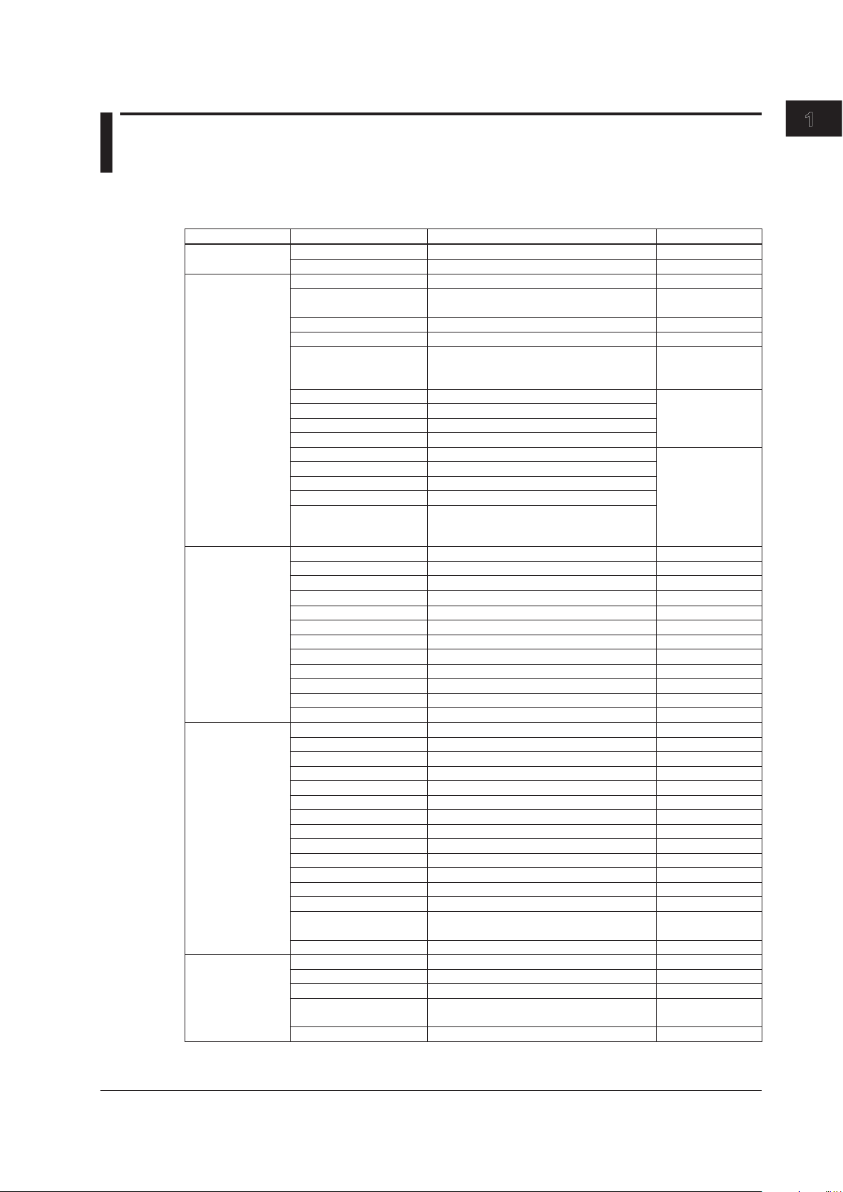
Duplicate Packet
Frames that are received more than once are counted as duplicate packets. The Duplicate Packet
number represents the total number of duplicate packets.
1 2 3 4 5 6 8 9 10 12 13 14 15 16 20
Loss Packet: 0
Max Burst Loss: 0
Reorder Packet: 0
Note
All consecutive reorder packets after the first are counted as duplicate packets.
1 2 3 4 5 6 89 10 12 13 14 15 16
Loss Packet: 1
Max Burst Loss: 2
Reorder Packet: 1
Loss1Burst loss
2
Duplicate
1
Wrong order
1
18 19177 11 9 107
Duplicate
2
711
→Duplicate
1
IM AQ1300-01EN
1-17
Page 26

1.7 Reception Features
Payload Error Measurement
Using the (16-bit) payload CRC data in fields in Rx frame test tags, the AQ1300 Series can check for
payload errors between itself and the other device.
BER Measurement
By inserting a pseudo-random pattern (PN15) into the fill pattern data area of a Tx frame payload and
then sending the Tx frame to the other device, the AQ1300 Series can perform a BER measurement to
check for device errors.
Condition for Synchronization
A sync loss state changes to a synchronized state when a matching PN pattern of 32 bits or more is
detected in the payload.
Condition for Sync Loss
A synchronized state changes to a sync loss state when an error of 50 bits or more is detected
within 128 bits.
Note
The bytes that undergo BER measurement include the first 32 bits that result in synchronization.
Pause
When Flow Control is set to ON and the AQ1300 Series detects a pause frame, it will stop transmission
until the pause time passes.
Collision Detection
When the interface is RJ-45 10BASE-T or 100BASE-TX and half duplex is selected, the AQ1300
Series detects collisions.
• Frames that are received when a collision is detected are considered invalid and are not used in
statistics.
• Late collisions (collisions that occur after a string of 512 bits that includes the preamble have been
sent) are treated as collisions.
1-18
IM AQ1300-01EN
Page 27
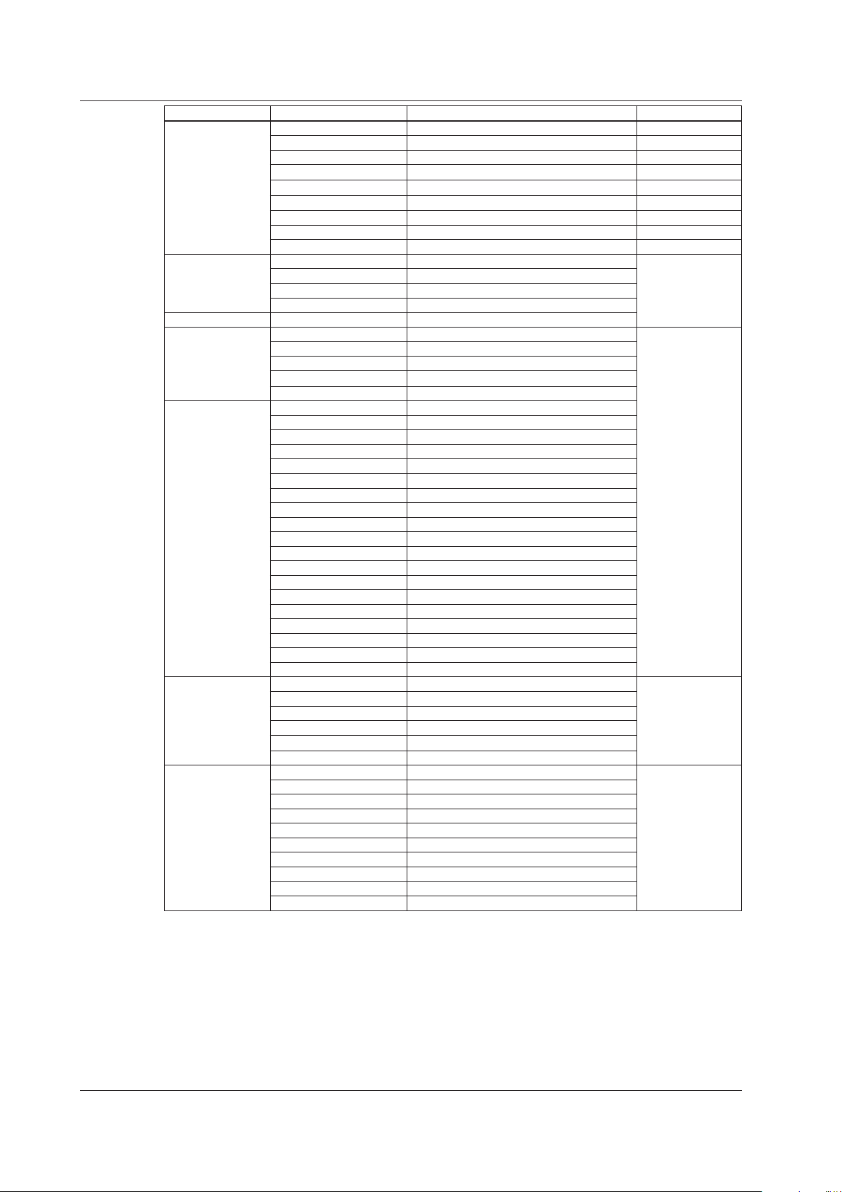
1.8 Statistics
List of Statistics
Group Name Display Display Digits Condition
Common Acquisition Time YYYY/MM/DD hh:mm:ss
Measurement Duration hh:mm:ss
Link Link Status Up to 22 characters
Laser Off Count 16-digit integer XFP or SFP
Linkdown Count 16-digit integer
Tx Freq Deviate(ppm) +/- sign and 1 digit after the decimal point
Rx Freq Deviate(ppm) +/- sign and 1 digit after the decimal point When the interface
LF Send Count 16-digit integer When the interface
RF Send Count 16-digit integer
LF Detect Count 16-digit integer
RF Detect Count 16-digit integer
LF receve column count 16-digit integer When the interface
RF receive column count 16-digit integer
66B sync loss count 16-digit integer
66B sync error count 16-digit integer
66B sync hi-ber count 16-digit integer
Tx Frame 16-digit integer
Byte 16-digit integer
Rate(%) 5 digits after the decimal point
Rate(fps) 10-digit integer
Rate(Bps)
Rate(bps)
Reply Frame 10-digit integer
Error Frame 16-digit integer
CRC Error 16-digit integer
Undersize Error 16-digit integer
Oversize Error 16-digit integer
Symbol Error 16-digit integer
Rx: Frame 16-digit integer
Byte 16-digit integer
Rate(%) 5 digits after the decimal point
Rate(fps) 10-digit integer
Rate(Bps)
Rate(bps)
Peak Rate(%) 5 digits after the decimal point
Peak Rate(fps) 10-digit integer
Peak Rate(bps) 10-digit integer
Average Rate(%) 5 digits after the decimal point
Average Rate(fps) 10-digit integer
Average Rate(bps) 10-digit integer
PAUSE Frame 16-digit integer
Collision Detect 16-digit integer When the interface
Error Frame 16-digit integer
Rx Error CRC Error 16-digit integer
Undersize Error 16-digit integer
Oversize Error 16-digit integer
Alignment Error 16-digit integer When the interface
Symbol Error 16-digit integer
1
Features
interface
is XFP, SFP, or
RJ-45 100BASE-TX
is XFP
is XFP.
Supported in
firmware version
(FW Ver.)
R1.08.01.001 and
later.
*
*
*
*
10-digit integer
10-digit integer
10-digit integer
10-digit integer
is RJ-45
is RJ-45
IM AQ1300-01EN
1-19
Page 28
1.8 Statistics
Group Name Display Display Digits Condition
Latency Max IFG(us) Integer part: 10 digits, fractional part: 1 digit
Min IFG(us) Integer part: 10 digits, fractional part: 1 digit
Avg IFG(us) Integer part: 10 digits, fractional part: 1 digit
Max IFG(bit) Integer part: 16 digits
Min IFG(bit) Integer part: 16 digits
Avg IFG(bit) Integer part: 16 digits
Max Latency(us) Integer part: 10 digits, fractional part: 1 digit
Min Latency(us) Integer part: 10 digits, fractional part: 1 digit
Avg Latency(us) Integer part: 10 digits, fractional part: 1 digit
Sequence Loss Packet 16-digit integer When the mode is
Reorder Packet 16-digit integer
Duplicate Packet 16-digit integer
Max Burst Loss 10-digit integer
Payload Error Payload Error 13-digit integer
Tx Channel (1 to 8) Frame 16-digit integer When the mode is
Byte 16-digit integer
Rate(%) 5 digits after the decimal point
Rate(fps) 10-digit integer
Rate(bps) 10-digit integer
Rx Channel (1 to 8) Frame 16-digit integer
Byte 16-digit integer
Rate(%) 5 digits after the decimal point
Rate(fps) 10-digit integer
Rate(bps) 10-digit integer
Peak Rate(%) 5 digits after the decimal point
Peak Rate(fps) 10-digit integer
Peak Rate(bps) 10-digit integer
Average Rate(%) 5 digits after the decimal point
Average Rate(fps) 10-digit integer
Average Rate(bps) 10-digit integer
Max Latency(us) Integer part: 10 digits, fractional part: 1 digit
Min Latency(us) Integer part: 10 digits, fractional part: 1 digit
Avg Latency(us) Integer part: 10 digits, fractional part: 1 digit
Loss Packet 16-digit integer
Reorder Packet 16-digit integer
Duplicate Packet 16-digit integer
Max Burst Loss 10-digit integer
Payload Error 13-digit integer
BERT Bit Error Rate (×E-12) Integer part: 13 digits, fractional part: 1 digit When the mode is
Bit Error Count 16-digit integer
Bit Error Frame 16-digit integer
Sync Loss Count 16-digit integer
BERT Target Byte 16-digit integer
Bit Error Insertion 10-digit integer
PING Send 16-digit integer When the mode is
Loss Count 16-digit integer
ARP Error Disable
IPv4 Checksum Error 16-digit integer
ICMP Checksum Error 16-digit integer
Timeout 16-digit integer
Loss Rate(%) Integer part: 3 digits, fractional part: 1 digit
Max Response Time(ms) Integer part: 3 digits, fractional part: 3 digits
Min Response Time(ms) Integer part: 3 digits, fractional part: 3 digits
Avg Response Time(ms) Integer part: 3 digits, fractional part: 3 digits
Traffic Test or QoS
Test
QoS Test
BERT
PING Test
1-20
* Bps: Byte/s, bps: bit/s
IM AQ1300-01EN
Page 29
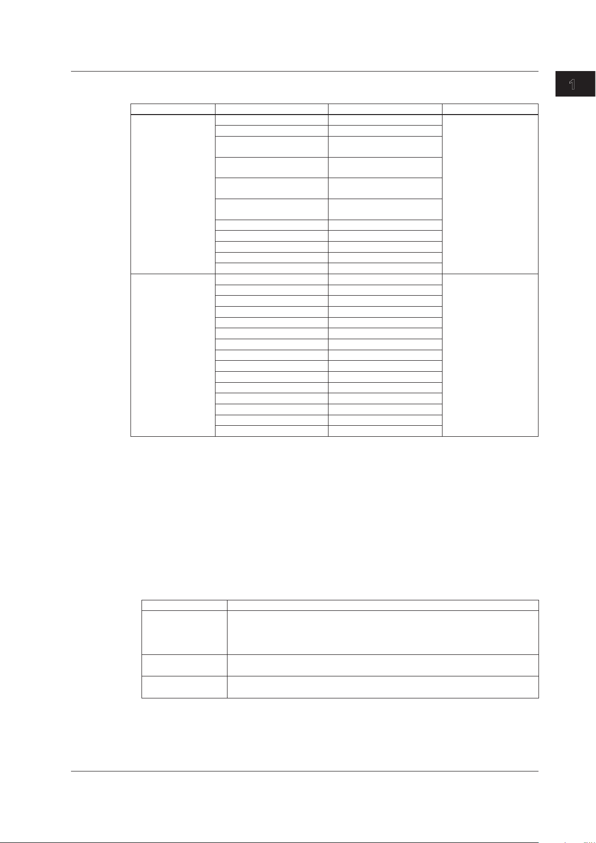
1.8 Statistics
E-OAM Test Statistics
Group Name Display Display Digits Conditions
LoopBack(LB) Test Count 16-digit integer When the mode is LB test
Loss Count 16-digit integer
Loss Rate Integer part: 3 digits, fractional
part: 1 digit
Max Response Time(ms) Integer part: 3 digits, fractional
part: 3 digits
Min Response Time(ms) Integer part: 3 digits, fractional
part: 3 digits
Avg Response Time(ms) Integer part: 3 digits, fractional
part: 3 digits
Link Down Count 16-digit integer
CRC Error 16-digit integer
Undersize Error 16-digit integer
Alignment Error 16-digit integer
Symbol Error 16-digit integer
Continuity Check(CC) Tx CCM count 16-digit integer When the mode is CC test
Tx RDI count 16-digit integer
Rx CCM count 16-digit integer
Rx RDI count 16-digit integer
LOC detected count 16-digit integer
Through CCM count 16-digit integer
UnExpected MEP count 16-digit integer
Mismerge count 16-digit integer
Unexpected MEG Level count 16-digit integer
Unexpected Period count 16-digit integer
Link Down Count 16-digit integer
CRC Error 16-digit integer
Undersize Error 16-digit integer
Alignment Error 16-digit integer
Symbol Error 16-digit integer
1
Features
Common Group
Acquisition Time
The time when the screen was last updated is displayed (YYYY/MM/DD hh:mm:ss).
Measurement Duration
The amount of time that has elapsed since the start of testing (statistics) is displayed (to the second;
hh:mm:ss).
Link Group
Link Status
The port UP/DOWN link status is displayed. When the status is UP, the connection speed and MDI
status are displayed.
IF Display
RJ-45 Linkdown-Unfixed, Linkdown-Straight, Linkdown-Cross
10M-FULL-Straight, 10M-FULL-Cross, 10M-HALF-Straight, 10M-HALF-Cross
100M-FULL-Straight, 100M-FULL-Cross, 100M-HALF-Straight, 100M-HALF-Cross
1000M-FULL-Straight, 1000M-FULL-Cross
SFP Linkdown
1000M-FULL
XFP Linkdown
10G-FULL
Laser Off Count
Indicates the number of times the laser has been turned off
IM AQ1300-01EN
Linkdown Count
Indicates the number of linkdown detections
1-21
Page 30

1.8 Statistics
Tx Freq Deviate(ppm)
Indicates the frequency deviation of the Tx clock
Rx Freq Deviate(ppm)
Indicates the frequency deviation of the Rx clock
LF Send Count and RF Send Count
Indicate the number of sent LFs and RFs
LF Detect Count and RF Detect Count
Indicate the number of detected LFs and RFs
LF Column Count and RF Column Count
Indicate the number of detected LF sequence column and RF sequence column. You can check the
status of reception frequency does not lead to detection LFS. This feature is supported in firmware
version (FW Ver.) R1.08.01.001 and later.
66B Sync Loss Count
Indicates the number of times the AQ1300 Series detected signal reception changes from a sync
(block lock) state to a loss of sync (block lock loss) state as defined in IEEE802.3.
This feature is supported in firmware version (FW Ver.) R1.08.01.001 and later.
66B Sync Error Count
Indicates the number of times the AQ1300 Series detected blocks whose sync header (2 bits) is 00
or 11 when signal reception is in a sync (block lock) state as defined in IEEE802.3.
This feature is supported in firmware version (FW Ver.) R1.08.01.001 and later.
66B Sync hi-ber Count
Indicates the number of times the AQ1300 Series detected 16 or more sync headers (2 bits) set
to00or11ina125μswindowwhensignalreceptionisinasync(blocklock)stateasdefinedin
IEEE802.3.
This feature is supported in firmware version (FW Ver.) R1.08.01.001 and later.
Tx Group
Frame
Indicates the number of frames that have been transmitted normally
Byte
Indicates the number of bytes in the frames that have been transmitted normally
Rate(%)
Indicates the data transmission rate (as a percentage)
Rate(fps)
Indicates the number of frames that have been transmitted normally in a single second
Rate(Bps)
Indicates the number of bytes in the frames that have been transmitted normally in a single second
Rate(bps)
Indicates the number of bits in the frames that have been transmitted normally in a single second
1-22
Reply Frame
Indicates the total number of emulation reply frames that have been transmitted
ARP/PING/PING6/NA
IM AQ1300-01EN
Page 31

1.8 Statistics
Error Frame
Indicates the total number of frames that have been sent with a CRC, undersize, oversize, or
symbol error
CRC Error
Indicates the number of frames that have been sent with a CRC error attached to FCS
Undersize Error
Indicates the number of transmitted frames that have been larger than 17 bytes but smaller than 64
bytes (not including the preamble but including the FCS)
Oversize Error
Indicates the number of transmitted frames whose size has been at or above the user-defined
oversize value (not including the preamble but including the FCS)
Symbol Error
Indicates the number of frames that have been sent with an error code attached to them
Rx Group
Frame
Indicates the number of frames that have been received normally
Byte
Indicates the number of bytes in the frames that have been received normally
1
Features
Rate(%)
Indicates the data reception rate (as a percentage)
Rate(fps)
Indicates the number of frames that have been received normally in a single second
Rate(Bps)
Indicates the number of bytes in the frames that have been received normally in a single second
Rate(bps)
Indicates the number of bits in the frames that have been received normally in a single second
Peak Rate
Indicates the highest rate detected during measurement (as a percentage, in fps, or in bps)
Average Rate
Indicates the average rate (as a percentage, in fps, or in bps) within the period during measurement
from the first normally received frame until the last normally received frame
* However, the data in the first and last 100 ms of the period is not included in the average rate calculation.
*
PAUSE Frame
Indicates the number of pause frames that have been received
Collision Detect
Indicates the number of collisions that have occurred
Collision Detect is only valid when Duplex is set to Half.
IM AQ1300-01EN
Error Frame
Indicates the total number of received frames that have had a CRC, undersize, oversize, alignment,
or symbol error
1-23
Page 32

1.8 Statistics
Rx Error Group
CRC Error
Indicates the number of frames in which FCS errors were detected.
The AQ1300 Series detects errors by comparing the CRC values calculated from the received
frames to the FCS (Frame Check Sequence) values in the received frames.
Undersize
Indicates the number of undersized frames.
An error occurs when a received frame is shorter than 64 bytes (excluding the preamble but
including the FCS).
• If the interface is XFP, frames shorter than 48 bytes will not be detected.
• If the interface is SFP or RJ-45, frames shorter than 18 bytes will not be detected.
Oversize
Indicates the number of oversized frames.
When a received frame is longer than the frame length that user defined (excluding the preamble
but including the FCS), a received frame is considered oversized.
When Manual has been selected in the Test menu, you can set the oversized frame length on the
Manual Setup screen. The factory default value is 1519 byte.
When Auto or Auto(Remote) has been selected in the Test menu and “Use Jumbo Frame” has not
been selected, frames that are longer than 1518 + the value set for “VLAN stacks” in the source
settings × 4 bytes are considered oversized.
Alignment Error
Indicates the number of alignment error frames.
An error occurs when a received frame's length is not in units of bytes and a FCS value is incorrect
(CRCerror).
An error will not occur if the FCS value is correct, even if a received frame's length is not in units of
bytes. Alignment errors are valid only for 10M and 100M connections.
Symbol Error
Indicates the number of received frames that contain symbol errors.
An error occurs when any of the following conditions is detected:
• If there are codes that cannot be encoded.
Errors are not detected if the interface is RJ-45 (10M connection).
• If the end value of a received frame is incorrect.
• If a link fault signaling (LFS) exists in a received frame.
(Interface type: XFP)
Latency Group
Max IFG (µs and bit)
Indicates the maximum interframe gap in terms of time and bits.
Min IFG (µs and bit)
Indicates the minimum interframe gap in terms of time and bits.
Avg IFG (µs and bit)
Indicates the average interframe gap in terms of time and bits.
1-24
Max Latency (µs)
Indicates the maximum difference between a frame’s timestamp and the time that it was received
Min Latency (µs)
Indicates the minimum difference between a frame’s timestamp and the time that it was received
IM AQ1300-01EN
Page 33

1.8 Statistics
Avg Latency (µs)
Indicates the average difference between a frame’s timestamp and the time that it was received
Sequence Group
Loss Packet
Indicates the total number of frames that have been lost. This is enabled when two or more
sequence measurement source frames are received.
Reorder Packet
Indicates the total number of frames that have been received out of the order that they were sent in.
This is enabled when two or more sequence measurement source frames are received.
Duplicate Packet
Indicates the number of received frames that have been received again. This is enabled when two
or more sequence measurement source frames are received.
Max Burst Loss
Indicates the maximum number of consecutive frames that have been lost. This is enabled when
two or more sequence measurement source frames are received.
Payload Group
Payload Error
Indicates the number of errors that have been detected in the received payloads. Payload error
detection is enabled when at least one sequence measurement source frame is received.
The AQ1300 Series detects errors by comparing the CRC values calculated from the payload in
received frames to the CRC values for payload checking that is included in the received frames.
1
Features
CH1 to CH8 Tx Groups
Frame
For each QoS channel, this item indicates the number of frames that have been transmitted from
the port normally
Byte
For each QoS channel, this item indicates the number of bytes in the frames that have been
transmitted normally
Rate(%)
Indicates the data transmission rate (as a percentage) for each QoS channel
Rate(fps)
For each QoS channel, this item indicates the number of frames that have been transmitted
normally in a single second
Rate(bps)
For each QoS channel, this item indicates the number of bits in the frames that have been
transmitted normally in a single second
CH1 to CH8 Rx Groups
Frame
For each QoS channel, this item indicates the number of frames that have been received normally
IM AQ1300-01EN
Byte
For each QoS channel, this item indicates the number of bytes in the frames that have been
received normally
1-25
Page 34

1.8 Statistics
Rate(%)
Indicates the data reception rate (as a percentage) for each QoS channel
Rate(fps)
For each QoS channel, this item indicates the number of frames that have been received normally
in a single second
Rate(bps)
For each QoS channel, this item indicates the number of bits in the frames that have been received
normally in a single second
Peak Rate
Indicates the highest rate detected during measurement (as a percentage, in fps, or in bps) for each
QoS channel
Average Rate
For each QoS channel, this item indicates the average rate within the period during measurement (as
a percentage, in fps, or in bps) from the first normally received frame until the last normally received
*
frame
* However, the data in the first and last 100 ms of the period is not included in the average rate calculation.
Max Latency(us)
For each QoS channel, this item indicates the maximum difference between a frame’s timestamp
and the time that it was received
Min Latency(us)
For each QoS channel, this item indicates the minimum difference between a frame’s timestamp
and the time that it was received
Avg Latency(us)
For each QoS channel, this item indicates the average difference between a frame’s timestamp and
the time that it was received
Loss Packet
For each QoS channel, this item indicates the total number of frames that have been lost. This is
enabled when two or more sequence measurement source frames are received.
Reorder Packet
For each QoS channel, this item indicates the total number of frames that have been received out of
the order that they were sent in. This is enabled when two or more sequence measurement source
frames are received.
Duplicate Packet
For each QoS channel, this item indicates the number of received frames that have been received
again. This is enabled when two or more sequence measurement source frames are received.
Max Burst Loss
For each QoS channel, this item indicates the maximum number of consecutive frames that have
been lost. This is enabled when two or more sequence measurement source frames are received.
1-26
Payload Error
For each QoS channel, this item indicates the number of errors that have been detected in the
received payloads. This is enabled when one or more payload error measurement source frames
are received.
IM AQ1300-01EN
Page 35

1.8 Statistics
BERT Group
Bit Error Rate
Indicates the bit error rate (E
received frame at least once (when the BERT target byte is not zero).
Bit Error Count
Indicates the number of bit errors detected during synchronization. This is enabled when the
AQ1300 Series synchronizes with the received frame at least once (when the BERT target byte
is not zero). The AQ1300 Series detects errors by comparing the CRC values calculated from the
payload in received frames to the CRC values for payload checking that is included in the received
frames.
Bit Error Frame
Indicates the number of received frames that contain a bit error. This is enabled when the AQ1300
Series synchronizes with the received frame at least once (when the BERT target byte is not zero).
Sync Loss Count
Indicates the number of sync loss occurrences. This is enabled when the AQ1300 Series
synchronizes with the received frame at least once (when the BERT target byte is not zero).
BERT Target Byte
Indicates the number of synchronized bytes that have been received
Bit Error Insertion
Indicates the number of inserted bit errors
-12
). This is enabled when the AQ1300 Series synchronizes with the
1
Features
PING Group
Test Count
Indicates the number of sent ping frames
Loss Count
Indicates the number of failed ping attempts
ARP Error
Indicates the number of failed ping attempts that resulted from ARP address resolution failures.
In the firmware version R1.07 and later, this item is always disabled because the address resolution
is executed before measurement.
IPv4 Checksum Error
Indicates the number of failed ping attempts that resulted from IPv4 header checksum errors
ICMP Checksum Error
Indicates the number of failed ping attempts that resulted from ICMP checksum errors
Timeout
Indicates the number of timeouts
Loss Rate(%)
Indicates the percentage of frames that have been lost as a result of timeouts
Max Response Time(ms)
Indicates the maximum response time
IM AQ1300-01EN
Min Response Time(ms)
Indicates the minimum response time
Avg Response Time(ms)
Indicates the average response time
1-27
Page 36

1.8 Statistics
LoopBack (LB) Group
Test Count
Indicates the number of sent LBM frames
Loss Count
Indicates the number of failed attempts
Loss Rate
Indicates the percentage of frames that have been lost as a result of timeouts
Max Response Time(ms)
Indicates the maximum response time
Min Response Time(ms)
Indicates the minimum response time
Avg Response Time(ms)
Indicates the average response time
Link Down Count
Indicates the number of link-down detections
CRC Error
Indicates the number of CRC error frames that have been received
Undersize Error
Indicates the number of undersize frames (less than 64 bytes) that have been received
Alignment Error
Indicates the number of alignment error frames that have been received
Symbol Error
Indicates the number of symbol error frames that have been received
Continuity Check (CC) Group
Tx CCM Count
Indicates the number of sent CCM frames
Tx RDI Count
Indicates the number of sent RDI frames
Rx CCM Count
Indicates the number of received CCM frames
Rx RDI Count
Indicates the number of received RDI frames
1-28
LOC Detected Count
Indicates the number of LOC (loss of continuity) detections
This is detected when three consecutive CCM frames cannot be received from the other network
device (MEP).
IM AQ1300-01EN
Page 37

1.8 Statistics
Through CCM Count
Indicates the number of received CCM frames whose maintenance domain level (MD level) is
higher than the MD level of the AQ1300 Series
Unexpected MEP Count
Indicates the number of unexpected MEP detections
This is detected when the maintenance domain level (MD level) and domain name in the received
CCM frame are correct but the MEP ID of the other network device (MEP) is different from the “target
MEP ID.” The domain name is either Short MA Name (IEEE802.1ag standard) or MEG ID (ITU-T
Y1731 recommendation).
Mismerge Count
Indicates the number of mismerge detections
This is detected when the maintenance domain level (MD level) in the received CCM frame is
correct but the domain name is not.
Unexpected MEG Level Count
Indicates the number of unexpected MEG level detections
This is detected when the maintenance domain level in the received CCM frame is less than the
MD level of the AQ1300 Series.
Unexpected Period Count
Indicates the number of unexpected period detections
This is detected when the maintenance domain level (MD level), domain name, and MEP ID in the
received CCM frame are correct but the transmission interval of the other network device (MEP) is
different from that of the AQ1300 Series.
1
Features
Link Down Count
Indicates the number of link-down detections
CRC Error
Indicates the number of CRC error frames that have been received
Undersize Error
Indicates the number of undersize frames (less than 64 bytes) that have been received
Alignment Error
Indicates the number of alignment error frames that have been received
Symbol Error
Indicates the number of symbol error frames that have been received
IM AQ1300-01EN
1-29
Page 38

1.9 Emulation
IPv4 Host
ARP Reply
To perform address resolution, the AQ1300 Series sends an ARP reply when it receives an ARP
request.
When you enable ARP replying, it is always enabled regardless of the test mode setting, filter
condition, or measurement or transmission condition.
When Auto or Auto(Remote) has been selected in the Test menu, ARP replying is always enabled and
set to “Source Address only.”
When Manual has been selected in the Test menu and the test layer is L3-IPv4, you can configure
ARP replying using the emulation settings.
ARP Requests That Are Not Answered
The AQ1300 Series will not send an ARP reply in response to the following kinds of ARP requests.
• ARP requests with a LLC/SNAP header attached (only ARP requests that conform to the DIX
specification are supported)
• ARP requests with an MPLS label attached
• ARP requests that are counted as errors, except for payload and sequence errors
• ARP requests that are received at the same time that a linkdown occurs
• ARP requests that are received at the same time that a collision occurs
• ARP requests whose packet lengths are less than 63 bytes, greater than 1519 bytes (greater
than 1523 when there is one VLAN stack or greater than 1527 when there are two VLAN stacks),
or greater than the oversize threshold.
• ARP requests with three or more VLAN stacks.
1-30
VLAN Tag Handling
The AQ1300 Series sends ARP replies in response to ARP requests with VLAN tags attached.
ARP Requests with Test Tags
The AQ1300 Series sends ARP replies in response to ARP requests with test tags attached.
ARP Reply Transmission Conditions
• If a collision occurs while an ARP reply is being sent, it is resent.
• If an ARP request is received while transmission is paused, an ARP reply is sent after
transmission is resumed.
• If transmission is paused and the AQ1300 Series is waiting to send an ARP reply and a normal
test frame, after transmission resumes, the AQ1300 Series will send the ARP reply first and then
the normal test frame.
• Replies are not sent for ARP requests that are received before the transmission of the current
ARP reply has finished.
• If a linkdown occurs immediately after an ARP request is received, the AQ1300 Series will not
send a reply to that request.
Ping Reply
The AQ1300 Series sends a ping reply when it receives a ping request.
When you enable ping replying and the test mode is not Loopback Test, ping replying is always
enabled regardless of the test mode setting, filter condition, or measurement or transmission condition.
When Auto or Auto(Remote) has been selected in the Test menu, ping replying is always enabled.
When Manual has been selected in the Test menu and the test layer is L3-IPv4, you can configure ping
replying by specifying the emulation settings.
IM AQ1300-01EN
Page 39

1.9 Emulation
Ping Requests That Are Not Answered
The AQ1300 Series will not send a ping reply in response to the following kinds of ping requests.
• Ping requests with an LLC/SNAP header attached (only ping requests that conform to the DIX
specification are supported)
• Ping requests with an MPLS label attached
• Ping requests that are counted as errors, except for payload and sequence errors
• Ping requests that are received at the same time that a linkdown occurs
• Ping requests that are received at the same time that a collision occurs
• Ping requests whose packet lengths are less than 63 bytes, greater than 10000 bytes, or greater
than the oversize threshold.
• IP fragmented ping requests
• Ping requests with three or more VLAN stacks.
VLAN Tag Handling
The AQ1300 Series sends ping replies in response to ping requests with VLAN tags attached.
Ping Reply Transmission Conditions
• If a collision occurs while a ping reply is being sent, it is resent.
• If a ping request is received while transmission is paused, a ping reply is sent after transmission
is resumed.
• If transmission is paused and the AQ1300 Series is waiting to send a ping reply and a normal
test frame, after transmission resumes, the AQ1300 Series will send the ping reply first and then
the normal test frame.
• Replies are not sent for ping requests that are received before the transmission of the current
ping reply has finished.
• If a linkdown occurs immediately after a ping request is received, the AQ1300 Series will not
send a reply to that request.
1
Features
Automatic MAC Address Acquisition
In automatic MAC address acquisition, the AQ1300 Series uses ARP processing to automatically
obtain the MAC address of the device under test (DUT) and then uses that address as the frame
destination MAC address.
Automatic MAC Address Acquisition Conditions
• When automatic acquisition is enabled, ARP acquisition is performed with the specified target
host (IP address) at the start of measurement. If the target host is not in the same segment as
the AQ1300 Series, ARP acquisition is performed with the default gateway.
(Acquisition is performed before measurement starts. Afterwards, the statistics are cleared and
measurement starts.)
• The AQ1300 Series waits for a reply after it sends an ARP packet. The timeout value is 1 second.
The AQ1300 Series will try again after timing out.
• The acquired MAC address is cleared at the start of the next test.
• If the MAC address increment feature is enabled, it has priority.
• If the variable field feature is enabled, it has priority.
Ignored ARP Replies
The following ARP replies are not recognized as ARP replies when they are received.
• ARP replies with an LLC/SNAP header attached (only ARP replies that conform to the DIX
specification are supported)
• ARP replies with an MPLS label attached
• ARP replies that are counted as errors, except for payload and sequence errors
• ARP replies that are received at the same time that a linkdown occurs
IM AQ1300-01EN
1-31
Page 40

1.9 Emulation
IPv6 Host
• ARP replies that are received at the same time that a collision occurs
• ARP replies whose packet lengths are less than 63 bytes, greater than 1519 bytes (greater than
1523 when there is one VLAN stack or greater than 1527 when there are two VLAN stacks), or
greater than the oversize threshold.
• ARP replies with three or more VLAN stacks.
Automatic IP Address Acquisition (DHCP)
In automatic IP address acquisition, the AQ1300 Series requests an address from the DHCP server
and then uses the acquired IPv4 address as the source IPv4 address.
Multi Host
If the test menu is set to Manual and the test layer is IPv4, this feature automatically generates multiple
MAC addresses from the VLAN ID or IP address information and make the AQ1300 Series emulate
multiple hosts in the VLAN.
• Returns ARP replies as a multi host.
• Automatically performs ARP acquisition of frame destination MAC addresses for each QoS channel
in Qos test mode. This feature also automatically generates frame source MAC addresses.
• Automatically configures Rx QoS filters for each QoS channel in QoS test mode.
NDP Reply
In NDP (Neighbor Discovery Protocol) replying, the AQ1300 Series resolves the address by sending
an NA (Neighbor Advertisement) when it receives an NS (Neighbor Solicitation). When you enable
NDP, it is always enabled regardless of the test mode setting, filter condition, or transmission condition.
When Auto or Auto(Remote) has been selected in the Test menu, NDP replying is always enabled.
When Manual has been selected in the Test menu and the test layer is L3-IPv6, you can configure
NDP replying by specifying the emulation settings.
NSs That Are Not Answered
The AQ1300 Series will not send an NA in response to the following kinds of NS.
• NSs with an LLC/SNAP header attached (only NSs that conform to the DIX specification are
supported)
• NSs with an MPLS label attached
• NSs that are counted as errors, except for payload and sequence errors
• NSs that are received at the same time that a linkdown occurs
• NSs that are received at the same time that a collision occurs
• NSs whose packet lengths are less than 81 bytes, greater than 10000 bytes, or greater than the
oversize threshold.
• NSs with three or more VLAN stacks.
VLAN Tag Handling
The AQ1300 Series sends NAs in response to NSs with VLAN tags attached.
1-32
NDP Requests with Test Tags
The AQ1300 Series sends NDP replies in response to NDP requests with test tags attached.
IM AQ1300-01EN
Page 41

1.9 Emulation
NA Transmission Conditions
• If a collision occurs while an NA is being sent, it is resent.
• If an NS is received while transmission is paused, an NA is sent after transmission is resumed.
• If transmission is paused and the AQ1300 Series is waiting to send an NA, an insert frame, and
a normal test frame, after transmission resumes, the AQ1300 Series will send the insert frame,
the NA, and then the normal test frame.
• NAs are not sent for NSs that are received before the transmission of the current NA has
finished.
• If a linkdown occurs immediately after an NS is received, the AQ1300 Series will not send a reply
to that request.
Ping6 Reply
In Ping6 replying, the AQ1300 Series sends a ping6 reply (ICMPv6 echo reply) when it receives a
ping6 request (ICMPv6 echo request).
When you enable ping6 replying and the test mode is not Loopback Test, ping replying is always
enabled regardless of the test mode setting, filter condition, or transmission condition.
When Auto or Auto(Remote) has been selected in the Test menu, ping6 replying is always enabled.
When Manual has been selected in the Test menu and the test layer is L3-IPv6, you can configure
ping6 replying by specifying the emulation settings.
Ping6 Requests That Are Not Answered
The AQ1300 Series will not send a ping6 reply in response to the following kinds of ping6 requests.
• Ping6 requests with an LLC/SNAP header attached (only ping6 requests that conform to the DIX
specification are supported)
• Fragmented ping6 requests.
• Ping6 requests with an MPLS label attached
• Ping6 requests that are counted as errors, except for payload and sequence errors
• Ping6 requests that are received at the same time that a linkdown occurs
• Ping6 requests that are received at the same time that a collision occurs
• Ping6 requests whose packet lengths are less than 81 bytes, greater than 1519 bytes (greater
than 1523 when there is one VLAN stack or greater than 1527 when there are two VLAN stacks),
or greater than the oversize threshold.
• Ping6 requests with three or more VLAN stacks.
1
Features
IM AQ1300-01EN
VLAN Tag Handling
The AQ1300 Series sends ping6 replies in response to ping6 requests with VLAN tags attached.
Ping6 Reply Transmission Conditions
• If a collision occurs while a ping6 reply is being sent, it is resent.
• If a ping6 request is received while transmission is paused, a ping6 reply is sent after
transmission is resumed.
• If transmission is paused and the AQ1300 Series is waiting to send a ping6 reply and a normal
test frame, after transmission resumes, the AQ1300 Series will send the ping6 reply first and
then the normal test frame.
• Replies are not sent for ping6 requests that are received before the transmission of the current
ping6 reply has finished.
• If a linkdown occurs immediately after a ping6 request is received, the AQ1300 Series will not
send a reply to that request.
1-33
Page 42

1.9 Emulation
Stateless Address Autoconfiguration
In stateless address autoconfiguration, the AQ1300 Series sends a router solicitation message to the
router and uses the router advertise message that it receives to set the source IPv6 address.
Ignored RAs
The following RAs are not recognized as RAs when they are received.
• RAs with an MPLS label attached
• RAs with an LLC/SNAP header attached (only RAs that conform to the DIX specification are
supported)
• RAs that are counted as errors
• RAs that are received at the same time that a linkdown occurs
• RAs that are received at the same time that a collision occurs
• RAs whose packet lengths are less than 81 bytes, greater than 1519 bytes (greater than 1523
when there is one VLAN stack or greater than 1527 when there are two VLAN stacks), or greater
than the oversize threshold.
• RAs with three or more VLAN stacks.
Automatic MAC Address Acquisition through NDP
In automatic MAC address acquisition through NDP, the AQ1300 Series uses NDP (neighbor discovery
protocol) message processing at the start of testing to automatically obtain the MAC address of the
IPv6 target host and then uses that address as the frame destination MAC address.
Automatic MAC Address Acquisition Conditions
• When automatic acquisition is enabled, MAC address acquisition through NDP is performed with
the specified target host (IP address) at the start of measurement. If the target host is not in the
same segment as the AQ1300 Series from the prefix length, MAC acquisition is performed with
the IPv6 router.
(Acquisition is performed before measurement starts. Afterwards, the statistics are cleared and
measurement starts.)
• The AQ1300 Series waits for a reply after it sends an NS (neighbor solicitation) packet. The
timeout value is 1 second. The AQ1300 Series will try again after timing out.
• The acquired MAC address is cleared at the start of the next test.
• If the MAC address increment feature is enabled, it has priority.
• If the variable field feature is enabled, it has priority.
1-34
IM AQ1300-01EN
Page 43

1.10 Ping and Traceroute Testing
Ping Test
You can perform IPv4/IPv6 ping testing.
• Destination: A single host
• Interval: 1 ms, 10 ms, 100 ms, 1 s
• Tx Mode: Frames, Time, Continuous
• Frame Length
IPv4: 64 (+up to two VLAN stacks) to 9999 bytes
IPv6: 84 (+up to two VLAN stacks) to 9999 bytes
Unsupported Ping Frames
• IEEE802.3 ping frames
• Fragmented ping frames
• Ping frames with an MPLS label attached
• Ping frames with three or more VLAN stacks.
Traceroute Test
You can perform IPv4 (ICMP) or IPv6 (ICMPv6) traceroute testing.
• Destination: A single host
1
Features
Unsupported Ping Frames
• IEEE802.3 ping frames
• Ping frames whose frame length is not 64 bytes (+VLAN tag)
• Ping frames with an MPLS label attached
• Ping frames with three or more VLAN stacks.
• Tests with more than 64 hops
IM AQ1300-01EN
1-35
Page 44

1.11 Logging Statistics
When Manual has been selected in the Test menu, you can log statistics on the AQ1300 Series.
The logged data is saved to a CSV file.
• Logging interval: 1 s
• Logging time: Specify the time in seconds up to 4 hours (14400 seconds), or
select 12, 24, 48, or 72 hours.
• End settings: Stop, Overwrite
• Maximum number of log items: 4
End Setting Description
Stop Logging stops after the logging time has passed.
Overwrite After the logging time has passed, old logs are overwritten by new logs.
Note
You can save logged statistics to a specific file name by opening the Measurement menu, selecting File,
selecting File Name Setup, and then specifying a file name.
1-36
IM AQ1300-01EN
Page 45

1.12 Simple Test Creation and Execution
Test Item Registration
When Auto or Auto(Remote) has been selected in the Test menu, you can perform different tests (test
modes) according to a test scenario that you have created in the setup software.
The test modes that have been registered in the test scenario are referred to as test items.
You can configure test items using the setup software. You can save up to eight test modes (test items)
to a single test scenario file.
You can execute tests by loading the setup file that you created with the setup software onto the
AQ1300 Series and selecting the configured test items.
Consecutive Test Item Execution
You can execute registered test items consecutively.
For consecutive test item execution, you can set the starting test number, the interval between test
items, and whether or not to display a confirmation message when a test item has finished.
1
Features
IM AQ1300-01EN
1-37
Page 46

1.13 Displaying Test Pass/Fail Results
When Auto or Auto(Remote) has been selected in the Test menu, you can display the pass/fail results
of measurement.
You can set the pass/fail conditions in the setup software for each test mode.
You can only use the AQ1300 Series to display the pass/fail conditions, not to set them. You can set
whether or not to perform pass/fail judgment.
For details about the pass/fail conditions, see the Setup Software User’s Manual, IM AQ1300-61EN.
1-38
IM AQ1300-01EN
Page 47

1.14 File
The AQ1300 Series and the setup software use the following files.
1
Features
File Type File Format Extension AQ1300 Series
(AQ1300 and AQ1301)
Save Load Save Load
Setup file Binary .sd Yes Yes Yes Yes
Management file Binary .dmf No Ye s Yes Ye s
Statistical result file Binary .mr Ye s Yes No Yes
Statistic log file Text .csv Ye s No No Yes
VLAN ID definition file Text .csv or .txt No Ye s No Yes
Setup Software
Setup File
A measurement setup file. You can register up to eight test items on a single setup file.
The type of setup file that you can save varies depending on what you select in the Test menu.
You cannot load a setup file that was created for a different Test menu option.
Management File
A file for managing the display of setup files. You can save four pages with 12 measurement setup files
each.
The management file name is fixed at “disManage.dmf”.
(Display management file)
Statistical Result File
A file of the measured results or the measured statistical results. You can save the results of one test
to a single statistical result file.
You can also automatically save a statistical result or a statistical result file whenever a test finishes.
Statistic Log File
When Manual has been selected in the Test menu, you can save up to four statistical items to a
statistic log file.
You can also automatically save a statistic log file whenever a test finishes.
VLAN ID Definition File
VLAN ID definition files (csv format; .csv or .txt extension) created in advance can be loaded into the
VLAN ID list of VLAN tests.
Note
• You can save a setup file to a specific file name by opening the Setup menu, selecting File, selecting File
Name Setup, and then specifying a file name.
• You can save a statistical result file or statistic log file to a specific file name by opening the Measurement
menu, selecting File, selecting File Name Setup, and then specifying a file name.
IM AQ1300-01EN
1-39
Page 48

1.15 Optical Power Measurement (AQ1300 Option)
On models with the /SPML option, when OPM has been selected in the Test menu, you can measure
optical power.
Wavelength range 850, 1300, 1310, 1490, 1550, 1625, 1650 nm
Measurement range –60 to +10 dBm
Modulation mode CW, 270 Hz, 1 kHz, 2 kHz
You can select the modulation frequency of the incident rays from a list. You can also
select CW (continuous).
Unit dB, dBm, W
Reference You can make the displayed measured value the reference and display subsequent
measured values as relative values.
Zero Set You can adjust the internal deviation of the optical power measurement section and obtain
more accurate absolute optical power values.
Average Count You can display averaged measured values.
Max/Min Value Display You can display the maximum and minimum measured values.
Offset You can add a specified value (the offset value) to measured optical power values.
Threshold Value You can set upper and lower threshold values and determine whether or not the measured
values fall within them.
1-40
IM AQ1300-01EN
Page 49

1.16 RFC2544 Measurement (AQ1300 Option)
Test traffic rate
One trial
RFC2544 was published by the IETF. This document contains evaluation methods (benchmark tests)
for measuring the processing capabilities of network devices.
The AQ1300 Series can perform the following measurements contained in RFC2544. The test
configuration that you need to use for these measurements is Loopback Traffic Test, in which the other
device is set to Loopback Test mode.
• Throughput
• Latency
• Frame loss rate
• Back to back
For each measurement, the length of transmit and receive frames is changed automatically to retrieve
a measured value. Then, the processing capability for each frame length is displayed on a graph.
In addition to the features listed above, the AQ1300 Series can measure the frame signal delay
variations when these frame signals travel across the network.
• Delay variations (packet jitter)
Throughput Measurement
The throughput measurement measures the maximum amount of traffic (rate) that a network device
can transmit without losing frame signals. In this measurement, a fixed number of frame signals are
transmitted (at the initial rate) over the specified measurement time (the test duration).
During the test duration, if a loss is detected, the rate is automatically decreased. The AQ1300 Series
performs another measurement to detect whether a loss occurs at this new rate. If a loss is detected,
the same operations are repeated. These operations are repeated until the rate is decreased to the
specified minimum rate.
During the test duration, if no losses are detected, the rate is automatically increased. The AQ1300
Series performs another measurement to detect whether a loss occurs at this new rate. If no losses
are detected, the same operations are repeated. These operations are repeated until the rate is
increased to the specified maximum rate.
These rate increasing and decreasing operations are repeated until the difference (the resolution)
between the rates when a loss was detected and when no losses were detected reaches a value that
is equal to or less than the specified value. The series of operations from the start of measurement to
the point where the rate converges to this specified value is a single measurement (a trial).
The specified number of trials are measured, and the average of the rates at the end of each trial is
the throughput value.
If a loss is detected at 100% test traffic rate, the rate is decreased to
100%
80%. If a loss is detected at a rate other than 100%, the rate is
decreased to half its original rate.
1
Features
IM AQ1300-01EN
80%
Loss
Loss
Fail
Fail
Test duration
60%
50%
40%
No
Loss Loss Loss
loss
Pass Pass
Fail Fail Fail
Measured result of the throughput test
47.5%
45%
Resolution
No
loss
Time
For the test configuration, see “Two-Way Traffic Test” in section 1.4.
1-41
Page 50

Test duration
Other device
Transmission and Reception of Frame Signals
1.16 RFC2544 Measurement
Test Duration
This is the length of one measurement for detecting losses.
Number of Trials
The number of times that the AQ1300 Series will perform the series of operations from the start
of measurement to the point where the rate converges to the specified value. In one trial, frame
signals of the preset frame lengths are used to perform the loss detection measurements. The
throughput is the average of the values from all the trials.
Initial Rate
The traffic rate that is used when the throughput measurement starts.
Minimum Rate
This is the lower limit for the rate. The rate is decreased automatically whenever a loss is detected.
This is the minimum traffic rate that is used to converge the throughput measurement.
Maximum Rate
This is the upper limit for the rate. The rate is increased automatically when no losses are detected.
This is the maximum traffic rate that is used to converge the throughput measurement.
Resolution
This is the range that is used to converge the throughput measurement. When the difference
between the rates when a loss was detected and when no losses were detected falls within the
resolution range, the AQ1300 Series concludes the throughput measurement.
Acceptable Loss
This threshold value specifies the percentage of a frame signal that can be lost without a loss being
detected.
Pass/Fail Judgment
You can perform pass/fail judgments by setting the throughput threshold on the AQ1300 Series in
advance. If the value falls below the threshold, a fail judgment occurs.
Latency Measurement
In the latency measurement, the AQ1300 Series measures the delay when a network device transmits
frame signals. In this measurement, a fixed number of frame signals are transmitted (at the test rate)
over the specified measurement time (the test duration). These frame signals are looped back by the
other device. The delay of the intermediate frame signal from the fixed number of frame signals is
measured.
Transmission
Network
Reception
One trial
Frame signal that is used for the
delay measurement
Loopback
1-42
IM AQ1300-01EN
Page 51

Store and forward delay
Time
Cut through delay
Time
1.16 RFC2544 Measurement
Selecting the Way That Measured Results Are Displayed
There are two transmission methods that can be used depending on the other network device. You
can select the method that the AQ1300 Series displays measured results with that is suitable for the
other device.
For the different transmission methods, the delay measurement method differs as shown in the
following figures.
• Store&Forward:
The delay of frame signals transmitted in the store and forward method is displayed.
• Cut Through:
The delay of frame signals transmitted in the cut through method is displayed.
Store and Forward Method
The time from when the last bit of the frame signal is received at the input port to when the first bit
of the frame signal is transmitted from the output port is measured as the delay.
Frame transmitted to the other device
1
Features
Frame received from the other device
Cut Through Method
The time from when the first bit of the frame signal is received at the input port to when the first bit
of the frame signal is transmitted from the output port is measured as the delay.
Frame transmitted to the other device
Test Duration
This is the time that frame signals are transmitted for during a single delay measurement.
Number of Trials
The number of times that delays are measured. For each trial, the delay measurement is performed
for the time specified by the test duration.In one trial, frame signals of the preset frame lengths are
used to perform the delay measurements. The delay is the average of the values from all the trials.
Test Rate
The traffic rate that the AQ1300 Series uses to measure the delay. You can change the test rate
value. If you have already performed the throughput measurement, you can set the traffic rate to
the measured throughput result.
Frame received from the other device
IM AQ1300-01EN
Pass/Fail Judgment
You can perform pass/fail judgments by setting the delay threshold on the AQ1300 Series in
advance.If the value exceeds the threshold, a fail judgment occurs.
1-43
Page 52

Test traffic rate
Time
Frame loss rate (%) =
Number of input frames - number of output frames
Number of input frames
×100
1.16 RFC2544 Measurement
Frame Loss Rate Measurement
In the frame loss rate measurement, frame signals are transmitted to the network device at a traffic
rate that exceeds the frame signal transfer capability of the network device, and the frame loss rate is
measured for each frame length.
In this measurement, the frame loss rate is measured while the rate is continually stepped down from
the initial rate that the measurement started at until losses are no longer detected.
The series of operations from the start of measurement to the finding of the rate at which losses are no
longer detected is a single measurement (a trial).
100%
90%
Loss
Loss
Fail
Fail
80%
70%
60%
50%
Loss Loss Loss
Fail Fail Fail
Loss
Fail
If no frame losses are detected for
two consecutive rates, no frame
signals at lower rates are measured.
40%
30%
No
No
loss
loss
Pass
Pass
The frame loss rate is computed using the following equation.
Test Duration
This is the time that frame signals are transmitted for during a frame loss rate measurement at a
single rate.
Number of Trials
The number of times that the AQ1300 Series will perform the series of operations from the start
of measurement to the point where the rate at which losses are no longer detected is found.
In one trial, frame signals of the preset frame lengths are used to perform the frame loss rate
measurements. The frame loss rate is the average of the values from all the trials.
Initial Rate
The traffic rate that is used when the frame loss rate measurement starts.
Step Down
After the measurement starts, the AQ1300 Series continually detects for losses while it automatically
decreases the traffic rate by the specified step.Measurement is stopped automatically when a rate
is found at which losses are no longer detected.
1-44
Pass/Fail Judgment
You can perform pass/fail judgments by setting the frame loss rate threshold (the rate’s upper limit)
on the AQ1300 Series in advance.If the value exceeds the threshold, a fail judgment occurs.
IM AQ1300-01EN
Page 53

Number of burst frames
One trial
The largest number of burst frames that
1.16 RFC2544 Measurement
Back to Back Measurement
In the back to back measurement, the maximum burst size (number of consecutive frames) that a
1
Features
network device can transmit without losing frame signals is measured. In this measurement, a burst of
frame signals (a group of consecutive frame signals) is transmitted over the specified measurement
time (the test duration).
During the test duration, if a loss is detected, the number of burst frames is automatically decreased.
The AQ1300 Series performs another measurement to detect whether a loss occurs with this new
number of burst frames. If a loss is detected, the same operations are repeated.
During the test duration, if no losses are detected, the number of burst frames is automatically
increased. The AQ1300 Series performs another measurement to detect whether a loss occurs with
this new number of burst frames. If no losses are detected, the same operations are repeated.
These operations that increase and decrease the number of burst frames are repeated until the
difference (the resolution) between the number of burst frames when a loss was detected and when no
losses were detected reaches a value that is equal to or less than the specified value.
The series of operations from the start of measurement to the point where the number of burst frames
converges to the specified value is a single measurement (a trial). The traffic rate is fixed to 100%.
29671
does not cause a loss to occur
22320
18600
14880
16740
17670
Resolution
No
Loss
Fail
Test duration
Loss Loss
loss
Pass Pass
Fail Fail Pass
No
loss
No
loss
Time
Test Duration
This is the length of one measurement for detecting losses.
Number of Trials
The number of times that the AQ1300 Series will perform the series of operations from the start
of measurement to the point where the number of burst frames converges to the specified value.
In one trial, frame signals of the preset frame lengths are used to perform the loss detection
measurements.
The number of burst frames is the average of the values from all the trials.
Resolution
This is the range that is used to converge the back to back measurement.When the difference
between the number of burst frames when a loss was detected and when no losses were detected
falls within the resolution range, the AQ1300 Series concludes the back to back measurement.
IM AQ1300-01EN
Pass/Fail Judgment
You can perform pass/fail judgments by setting the threshold on the number of burst frames (the
lower limit on the number of frames) on the AQ1300 Series in advance.If the value falls below the
threshold, a fail judgment occurs.
1-45
Page 54

Variation width (maximum)
Delay
Test duration
1.16 RFC2544 Measurement
Delay Variation (Packet Jitter) Measurement
In the delay variation measurement, the AQ1300 Series measures the delay variations when a network
device transmits frame signals. In this measurement, a fixed number of frame signals are transmitted
(at the test rate) over the specified measurement time (the test duration). The AQ1300 Series then
measures the frame signal delay in units of the specified test window size.
The maximum variation width and minimum variation width of the delays are measured per sampling
period. For each sampling period, the largest and smallest values are selected as the measured
results for the sampling period and are displayed on a graph. Additionally, the statistically processed
variation widths of each sampling period are displayed on the graph as percentile variations.
Sampling time
Time
Test Duration
This is the length of one measurement for measuring delay variations.
Number of Trials
The number of times that delay variations are measured. For each trial, the delay variation
measurement is performed for the time specified by the test duration.In one trial, frame signals of
the preset frame lengths are used to perform the delay variation measurements.
The delay variation is the average of the values from all the trials.
Test Rate
The traffic rate that the AQ1300 Series uses to measure the delay variation. You can change the
test rate value. If you have already performed the throughput measurement, you can set the traffic
rate to the measured throughput result.
Test Window Size (Sampling Time)
The AQ1300 Series measures frame signal delay variations in units of the specified length of time.
Resolution
This is the percentile variation value’s measurement resolution. The variation value measurement
ranges for all the resolutions are shown below.
Resolution Measurement Range
0.05 ms 0 ms to 3.00 ms
0.1 ms 0 ms to 6.00 ms
0.5 ms 0 ms to 30.00 ms
1.0 ms 0 ms to 60.00 ms
2.5 ms 0 ms to 150.00 ms
5.0 ms 0 ms to 300.00 ms
If you set Resolution to Auto, the AQ1300 Series statistically processes the frame signal delay that
was sampled during the preliminary measurement, which was done before the start of the test, and
automatically sets the resolution to the most appropriate value.
1-46
IM AQ1300-01EN
Page 55

Statistical value (number of samples)
corresponds to sample number 3750, which is in this class.
Example: 5000 samples
1.16 RFC2544 Measurement
Calculation Criterion for Result
The AQ1300 Series uses this setting to select the variation value from the statistically processed
values. During statistical processing, the value that you specified with the measurement resolution
specifies the class interval, and the size of the statistically processed values is split into 60 classes.
The AQ1300 Series sets the percentile value to the largest value that is within the class that
contains the value that corresponds to the threshold value.
• Example of the 75th percentile: In a single period of the test duration, 5000 values (statistically
processed values) were measured. Starting from the
first measurement, the value that corresponds to 75% is
measurement number 3750. Each class contains a certain
number of statistically processed values, and the percentile
value is set to the largest value within the class that contains
measurement number 3750.
The threshold is the 75th percentile. In this example, this
2000 samples
However, the AQ1300 displays the maximum value of this
class as the percentile value.
Percentile value = 0.15 ms
1500 samples
1
Features
Pass/Fail Judgment
You can perform pass/fail judgments by setting the delay variation threshold (the variation value’
s upper limit) on the AQ1300 Series in advance.If the value exceeds the threshold, a fail judgment
occurs.
500 samples
200 samples
0.01 ms
0.02 ms
0.02 ms
•
•
•
0.04 ms
Class 1
0.00 ms to
0.05 ms
0.07 ms
0.07 ms
0.08 ms
•
•
•
0.10 ms
Class 2
0.05 ms to
0.10 ms
0.11 ms
0.12 ms
0.12 ms
•
•
•
0.14 ms
Class 3
0.10 ms to
0.15 ms
0.16 ms
0.16 ms
0.17 ms
•
•
•
0.18 ms
Class 4
0.15 ms to
0.20 ms
. . .
Resolution: 0.05 ms
. . .
IM AQ1300-01EN
1-47
Page 56

1.17 VLAN Test
The VLAN Test is used to check the VLAN trunk configuration. You can compare the VLAN ID list that
you plan to receive with the actual received VLAN ID list. Then, you can display the results or save
them to a file.
Transmission
The AQ1300 Series transmits VLAN ID frames according to the VLAN ID list set on the AQ1300 using
up to 4096 VLAN IDs. A VLAN ID definition file can also be loaded into the VLAN ID list.
Transmittable Frame Formats
• When the test layer is L2: MAC+TYPE(0x00)
• When the test layer is L3-IPv4: MAC+TYPE+IPv4
MAC+TYPE+IPv4+UDP
• When the test layer is L3-IPv6: MAC+TYPE+IPv6
MAC+TYPE+IPv6+UDP
Reception and Analysis
The AQ1300 Series compares the list of the VLAN IDs that are planned to be received with the actual
received VLAN IDs and displays the result. You can edit VLAN ID lists on the AQ1300 Series or load
VLAN ID definition files into the VLAN ID list.
Display Format
Map or list
The comparison results are displayed in different colors: Rx ID success (green), Rx ID fail (yellow),
and RX ID error (red).
Saving Result Files
Received and analyzed result files can be saved in the AQ1300 Series in binary format (.mr extension).
Saved result files can be uploaded to a Windows PC with the Setup Software.
1-48
IM AQ1300-01EN
Page 57

1.18 Telnet Remote Control
The AQ1300 Series can be controlled remotely as a Telnet server. This feature is supported in auto
test or auto(remote) test modes. For details, see the Communication Interface User’s Manual, IM
AQ1300-17EN.
1
Features
IM AQ1300-01EN
1-49
Page 58

1.19 E-OAM Test
The AQ1300 Series is equipped with an Ethernet OAM (Ethernet operation, administration and
maintenance; hereafter referred to as E-OAM) function that complies with the ITU-T Y.1731
Recommendation and IEEE802.1ag Standard. The following tests can be performed.
• CC (continuity check) test
• LB (loop back) test, multicast LB execution
• LT (link trace) execution
Overview of the E-OAM Test
The E-OAM test checks the connection of network devices that are connected to a network segment
configured with an E-OAM router. In this test, the AQ1300 Series sends E-OAM frames and checks
whether response frames are returned from devices connected at the far end of the network (MEP;
maintenance end point) or routers connected in the middle of the network (MIP; maintenance
intermediate point).
Moreover, another AQ1300 Series, functioning as an emulator, can be connected in place of the other
network device (MEP) and return response frames to the AQ1300 Series on the transmitting end.
AQ1300 Series
CC test
LB test
CCM frame
transmission
LBM frame
transmission
LBM frame reception
Router 1
(MIP)
Router 2
(MIP)
Other device
LB reply
LT reply
Network
device (MEP)
1-50
LTM frame
LT execution
transmission
LTR frame reception
LTR frame reception
LTR frame reception
CC test
CC (Continuity Check) is a test in which CCM frames (Continuity Check Message) are sent periodically
to a device (MEP) at the far end of the network in order to check whether the route to the device is
connected. You can set the transmission interval to 100 ms, 1 s, 10 s, or 60 s. When the route is
disconnected (LOC: loss of continuity detection), an RDI (remote defect indication) frame is transmitted
to the network device at the destination address.
IM AQ1300-01EN
Page 59

1.19 E-OAM Testt
When LOC Is Detected
When a loss of continuity is detected (CCM frame is not received), if the auto RDI transmission
is enabled on the AQ1300 Series, an RDI frame is sent to the network device at the destination
address.
Network
device (MEP)
* RDI frames refer to periodically sent CCM frames with the RDI bit set to on.
LB Test
LB (Loop Back) is a test in which LBM (loopback message) frames are sent to a device (MEP) at the
far end of the network to check whether LBR (loopback reply) frames are returned from the device.
LB Test Mode
Set the length of the LB test.
CCM frame
transmission
Router 1
(MIP)
1
Features
AQ1300 Series
Router 2
(MIP)
LOC detection
RDI frame
transmission*
Tx mode: Time
Tx mode: Continue
Tx mode: Frames
Transmission period (e.g., 3 minutes)
Interval
Frame length
LBM frame 1 LBM frame 2 LBM frame 3
Test start (START) Test stop (STOP)
Interval
Frame length
LBM frame 1
Frames (e.g., 500 frames): LBM frame 1 to LBM frame 500
LBM frame 2 LBM frame 3
IM AQ1300-01EN
Interval
Frame length
LBM frame 1 LBM frame 2 LBM frame 3
LBM frame 500
1-51
Page 60

1.19 E-OAM Test
If LB reply is enabled in the AQ1300 Series emulation settings, when an LBM frame addressed
LT Execution
LT (link trace) can be used to send LTM frames to a device (MEP) at the far end of the network and
check whether LTR (link trace reply) frames are returned from all the routers in the middle receiving the
LTM (link trace message) frames. The MAC addresses of routers and network devices that responded
are listed in the AQ1300 Series measurement screen.
Multicast LB Execution
Multicast LB (loop back) can be used to send multicast LBM frames to network devices connected
to the same network segment and receive LBR frames from them. The MAC addresses of network
devices that responded are listed in the AQ1300 Series measurement screen.
LB Reply
to the AQ1300 Series is received, an LBR frame is sent to the network device at the destination
address.
1-52
IM AQ1300-01EN
Page 61

1
Screen during Measurement
Screen after Measurement Has Finished
(In Auto or Auto(Remote) mode without pass/fail judgment or in
Screen after Measurement Has Finished
(In Auto or Auto(Remote) mode with pass/fail judgment)
“over” is displayed when
Chapter 2 Screen Explanations
2.1 Measurement Screens (Common Items)
This section explains the common items in the measurement screens.
Test information
Link status
Title bar
Measurement status
Summary
Test results
Error History
Number of detected
errors (0 to 999)
Remote control status
2
Screen Explanations
the number of detected
errors exceeds 999.
Manual mode)
Pass/fail indication (Pass, Fail)
IM AQ1300-01EN
2-1
Page 62

2.1 Measurement Screens (Common Items)
Title Bar
Simple Optical Power Monitor
When the interface is XFP or SFP, the AQ1300 Series can monitor the received optical power level
and indicate it using three levels.
Indication Colors Description
If you are using optical modules that are not recommended on an AQ1300 Series whose firmware
version is R1.05.01.001 or later, black and black is displayed.
Current Time
The current time is displayed (YYYY/MM/DD hh:mm:ss).
Selected Setup File
When Auto or Auto(Remote) has been selected in the Test menu, the comment or file name that has
been specified by the setup file selection is displayed.
When Manual has been selected in the Test menu, the file name is displayed.
Displayed characters: Up to 30
Note
When Auto(Remote) has been selected in the Test menu and the screen is sent from the master to the slave,
“Send Screen Image” appears on the slave.
Black and black When the RJ-45 interface is being used or when the XFP or SFP interface is
Red and black When the level of received light is too low
Green and green When the level of received light is appropriate
Red and red When the level of received light is too high
being used and the interface module is not installed
Link Status Indication
The link status is indicated.
Indication Color Description
Blue Linkdown
Green Linkup
Power Supply Status Indication
The power supply status is indicated.
Indication Color Description
— The AC adapter is being used.
Green The battery is sufficiently full.
Yellow The battery is about half full.
Red The battery is almost empty.
Test Information
The test type, mode, and item execution status are indicated.
Information Type Indication Description
Test type Auto Auto mode
Auto (RMT) Auto(Remote) mode
Manual Manual mode
Test mode Traffic Traffic mode
Loopback Loopback mode
QoS QoS test mode
PING PING test mode
BERT BERT mode
Test item execution
status
1 to 8 The number of the test item that is currently being executed or is
The test type is Auto or Auto(Remote), and Execution Type is set to
Single.
The test type is Auto or Auto(Remote), and Execution Type is set to
Continue.
currently selected. The number blinks when the test item is being
executed.
2-2
IM AQ1300-01EN
Page 63

1
2.1 Measurement Screens (Common Items)
Link Status Indications
The link status is indicated.
Category Status Name Status Indication Description
L1 I/F type XFP The XFP interface is selected.
SFP The SFP interface is selected.
RJ-45 The RJ-45 interface is selected.
Module type SR The I/F type is XFP, and the module type is SR.
LR The I/F type is XFP, and the module type is LR.
ER The I/F type is XFP, and the module type is ER.
SX The I/F type is SFP(GbE), and the module type is SX.
LX The I/F type is SFP(GbE), and the module type is LX.
FX The I/F type is SFP(FE), and the module type is FX.
— The I/F type is RJ-45.
? No module is installed, or the module that is installed is
unsupported.
Link LINK (gray) Linkdown
LINK (green) Linkup
LINK (yellow) Auto negotiation configuration mismatch
Connection
speed
Duplex ? The duplex has not been confirmed (because of a linkdown
MDI/MDI-X — An optical interface is selected.
Flow control PAUSE/COL (red) A PAUSE frame is being received, or a collision that is
Frame TX TX (green) Frames are being sent.
RX RX (green) Frames are being received.
ERROR L2 ERR (red) An L2 error frame is being received.
LFS LF transmission Tx-LF (red) An LF signal is being sent.
RF transmission Tx-RF (red) An RF signal is being sent.
LF reception Rx-LF (red) An LF signal is being received.
RF reception Rx-RF (red) An RF signal is being received.
? The connection speed has not been confirmed (because of a
linkdown or some other reason).
10M 10 Mbps
100M 100 Mbps
1G 1 Gbps
10G 10 Gbps
or some other reason).
FULL Full duplex
HALF Half duplex
? Whether the interface is MDI or MDI-X has not been
confirmed (because of a linkdown or some other reason).
MDI MDI interface
MDI-X MDI-X interface
currently taking place has been detected.
PAUSE/COL
(orange)
PAUSE/COL (grey) No PAUSE frames have been received, and no collisions
TX (gray) Frames are not being sent.
RX (gray) Frames are not being received.
L2 ERR (orange) An L2 error frame has been received.
L2 ERR (gray) No L2 error frames have been received.
Tx-LF (gray) No LF signals have been or are being sent
Tx-RF (gray) No RF signals have been or are being sent
Rx-LF (orange) An LF signal has been received.
Rx-LF (red) No LF signals have been received.
Rx-RF (orange) An RF signal has been received.
Rx-RF (gray) No RF signals have been received.
A PAUSE frame has been received, or a collision has been
detected.
have been detected.
2
Screen Explanations
IM AQ1300-01EN
2-3
Page 64

2.1 Measurement Screens (Common Items)
Measurement Status Indications
The measurement status is indicated.
Status Name Status Indication Description
Tx time The remaining Tx time/
number of frames
Statistic logging STAT LOG (gray) Statistic logging is stopped.
STAT LOG (blue) Statistic logging is in progress.
Optical output off
control
LFS control LFS Control (gray) LF and RF signals are not being sent.
LASER OFF (gray) The laser is not off.
LASER OFF (red) The laser is off.
LFS Control (red) LF and RF signals are being sent.
Summary
A summary of the settings is displayed, or the addresses are displayed.
• Summary: A summary of representative settings is displayed. For details, see section 2.2.
• Address: The source and destination MAC and IP addresses are displayed.
For information about switching between the summary and the address display, see section 7.6.
Remote Control Status Indications
The remote control status is indicated.
Except for the unconnected status, all the statuses are for when the test type is Auto(Remote).
Status Name Status
Indication
Unconnected
The remaining time is indicated in seconds.
The remaining number of frames is indicated
by a number from 0 to 99999999.
Description
• A test type other than Auto(Remote) is selected.
Disconnected
-Master settings/results
Disconnected
-Slave settings/results
Connected
No slave statistic errors
-Master control
Connected
Slave statistic errors
-Master control
Connected
No slave statistic errors
-Slave control
Connected
Slave statistic errors
-Slave control
• The test type is Auto(Remote).
• The remote control status is “disconnected.”
• The settings and results for the master are displayed.
• The test type is Auto(Remote).
• The remote control status is “disconnected.”
• The settings and results for the slave are displayed.
• The test type is Auto(Remote).
• The remote control status is “connected.”
• The slave has no statistic errors.
• The settings, results, and controls are all for the master’s ports.
• The test type is Auto(Remote).
• The remote control status is “connected.”
• The slave has statistic errors.
• The settings, results, and controls are all for the master’s ports.
• The test type is Auto(Remote).
• The remote control status is “connected.”
• The slave has no statistic errors.
• The settings, results, and controls are all for the slave’s ports.
• The test type is Auto(Remote).
• The remote control status is “connected.”
• The slave has statistic errors.
• The settings, results, and controls are all for the slave’s ports.
Test Result Indications
Common Items
Pass/Fail Indication
This indication appears when the test type is Auto or Auto(Remote) and you have chosen to perform
pass/fail judgment.
• Pass: The results meet the requirements.
• Fail: The results do not meet the requirements.
2-4
IM AQ1300-01EN
Page 65

1
2.1 Measurement Screens (Common Items)
Measurement Indication
“Measuring” appears while measurement is being performed.
Measurement Duration Indication
The measurement duration is indicated in the following format: hh:mm:ss.
Transmission and Reception Rates
During measurement, the transmission and reception rates are indicated (as percentages).
Normal Frames
The number of normal frames that have been sent and received during the measurement period is
indicated.
Received Frame Length
The average frame length of the frames that have been received during measurement is indicated.
Error History
During measurement, link errors, L2 errors (L2 frame errors), and L3 errors (payload errors,
sequence errors, etc.) are detected and displayed.
Display Item Indication Description
LINK LINK (gray) No linkdowns have been detected during measurement.
LINK (red) If even one linkdown is detected during measurement, the indication
becomes red and display the number of detected errors. “over” is
displayed when the number of detected errors exceeds 999.
L2 L2 (gray) During measurement, no frames have been received with any of the
following errors.
• CRC errors
• Undersize errors
• Oversize errors
• Symbol errors
• Alignment errors
L2 (red) During measurement, if even one frame is received with any of the
following errors, the indication becomes red and display the number
of detected errors. “over” is displayed when the number of detected
errors exceeds 999.
• CRC errors
• Undersize errors
• Oversize errors
• Symbol errors
• Alignment errors
L3 L3 (gray) During measurement, no frames have been received with any of the
following errors.
• Bit errors
• Sequence errors
• Payload errors
L3 (red) During measurement, if even one frame is received with any of the
following errors, the indication becomes red and display the number
of detected errors. “over” is displayed when the number of detected
errors exceeds 999.
• Bit errors
• Sequence errors
• Payload errors
2
Screen Explanations
The number of detected errors is cleared when:
• Measurement is started
• Setup data is loaded
• You log in to the AQ1300 Series
Test-Mode-Specific Items
Different measurement items are displayed for different test modes. For details, see section 2.2.
IM AQ1300-01EN
2-5
Page 66

2.2 Measurement Screens (Test-mode-specific
Traffic Test
Loopback Test
QoS Test
items)
This section explains the test-mode-specific items in the measurement screens.
Summary
(Tx rate; Tx time, frames, or elapsed
time; frame length, fill pattern)
Test-mode-specific indications
(Rx rate, packet latency)
Summary (loopback target)
Test-mode-specific indications (none)
2-6
Summary (Tx rate for each channel)
Test-mode-specific indications
(Rx rate for each channel)
IM AQ1300-01EN
Page 67

1
PING Test
BERT
2.2 Measurement Screens (Test-mode-specific items)
Summary
(destination IP address, Tx interval,
number of frames)
Test-mode-specific indications
(loss count, sequence number, round
trip time, packet length, TTL)
Summary
(Tx rate; Tx time, frames, or elapsed
time; frame length)
Test-mode-specific indications
(bit error rate, bit error, BERT target byte)
2
Screen Explanations
IM AQ1300-01EN
2-7
Page 68

2.2 Measurement Screens (Test-mode-specific items)
Summary
A summary of the settings is displayed, or the addresses are displayed.
• Summary: Representative settings are displayed.
Test Mode Displayed Items
Traffic Test Tx rate; Tx time (when Tx Mode is set to Time), number of frames (when Tx Mode is
set to Frames), or elapsed time (when Tx Mode is set to Continuous); frame length;
fill pattern
Loopback Test Loopback target
QoS Test Tx rate for each channel
PING Test Destination IP address, Tx interval, Tx time (when Tx Mode is set to Time), number
of frames (when Tx Mode is set to Frames), or elapsed time (when Tx Mode is set to
Continuous)
BERT Tx rate; Tx time (when Tx Mode is set to Time), number of frames (when Tx Mode is
set to Frames), or elapsed time (when Tx Mode is set to Continuous); frame length
• Address: The source and destination MAC and IP addresses are displayed.
For information about switching between the summary and the address display, see section 7.6.
Test-Mode-Specific Indications
A summary of the test results is displayed.
Test Mode Displayed Items
Traffic Test Maximum Rx rate (%, fps, bps), maximum packet latency (us)
Average Rx rate (%, fps, bps), average packet latency (us)
Loopback Test None
QoS Test Maximum Rx rates for each channel (%, fps, bps)
Average Rx rates for each channel (%, fps, bps)
Current Rx rates for each channel (%, fps, bps)
PING Test Loss count, sequence number, round trip time, packet length, TTL
BERT Bit error rate, bit error, BERT target byte
Explanations of PING Test Mode Items
Indication Description
Loss Count Indicates the number of failed ping attempts
Seq. No. Indicates the sequence number.
Round Trip Time(ms) Indicates the round trip time in ms.
<1: Indicates a value of less than 1 ms
Value: The value in ms
Timeout: Indicates a timeout
Length Indicates the packet length.
TTL Indicates the TTL.
2-8
IM AQ1300-01EN
Page 69

2
1
-
A dialog box appears when you press
When you press the soft key, the item
Menu operation types A through C are listed
Chapter 3 Common Operations
3.1 Key, Rotary Knob, and Arrow Key Operations
This chapter explains key, rotary knob, and arrow key operations and the ways that they are explained
throughout the rest of the manual.
To make this manual easier to read, we have abbreviated or simplified explanations of the kinds of
operations listed below.
• Repetitive operations.
• Detailed operations for proceeding to the desired setup menu or dialog box and information about
the accompanying screen changes.
• Setup items that users can configure if they have a general understanding of them.
Key Operations
The examples below explain the process for turning on the power, waiting for the top menu to appear,
and then opening the File menu.
Press the Manual soft key (F3) to display the Manual Setup (1/2) menu.
1.
Press the Next 1/2 soft key (F5) to display the Manual Setup (2/2) menu.
2.
Press the File soft key (F3) to display the File menu.
3.
3
Common Operations
Execution
below.
A
A: A selection menu appears when you
press the soft key. When you press a
soft key that corresponds to an item
A
on the menu, the selected item is con
firmed, or the action that corresponds
A
to it is performed.
B:
B
the soft key.
ESCESC
MENUMENU
Note
If you press MENU to return to the top menu, the settings that you have configured up to that point are
•
saved as the latest setup.
If you changed the top menu display type, key operations are different. For details, see the explanation in
•
section 13.6.
If you have not changed the settings and have not performed any measurements, the confirmation
•
message that appears when you press MENU will not appear.
If you press ESC on the first page of a setup menu (Auto, Auto(Remote), Manual, Option, or System), the
•
AQ1300 Series will operate in the same manner as when MENU is pressed.
MENU
To return to the previous menu, press ESC.
To return to the top menu, press MENU.
C:
C
that corresponds to it is confirmed,
or the action that corresponds to it is
performed.
IM AQ1300-01EN
3-1
Page 70

omitted, and the settings that the soft keys
3.1 Key, Rotary Knob, and Arrow Key Operations
About the Explanations in this Manual
In this manual, steps 1 through 3 listed previously and the setup operations in the menu that follows
them are written as shown below.
Setup Operation Example
Press the Manual soft key, the Next 1/2 soft key, and then the File soft key to display the following
screen.
Set the action.
• Step numbers are used when there are many operations and when operations must be
performed in different menus.
• The explanation for returning to the previous menu is omitted.
Select a drive (Internal, USB Memory).
Set the file name.
Saves the file
At this point, the soft key names are
are used to configure and the actions
that pressing them causes are explained.
Options and ranges are listed afterwards.
3-2
IM AQ1300-01EN
Page 71

2
1
To return to the top menu, press MENU.
The item at the cursor location
Setup operation types D through H are
G
3.1 Key, Rotary Knob, and Arrow Key Operations
Rotary Knob and Arrow Key Operations
This section explains how to operate a menu and the operations to perform when a setup dialog box
appears. As an example, we will use the dialog box that appears when you press the System soft key
and then the System softkey in the system setup.
Press the System soft key (F5) to display the system menu.
1.
Press the System soft key to display the System Setup dialog box.
2.
Use the rotary knob or the arrow keys to move the cursor to the item that you want to
3.
configure or execute.
The item at the cursor location is highlighted.
Press ENTER.
4.
• Next, follow the instructions in the figure below that correspond to the type of item that you are
configuring or executing.
• In this manual, steps 3 and 4 listed above are indicated using the expression “using the rotary knob
and ENTER.”
3
Common Operations
is highlighted.
listed below.
Press ENTER to confirm the item or
D:
execute its corresponding action.
Press ENTER to display a menu. Turn
E:
E
the rotary knob or press the up and
F
down arrow keys to move the cursor
to the item that you want to select.
Then press ENTER to select the item.
H
The selected setting switches each
F:
time you press ENTER.
Press ENTER to display a text box.
G:
Turn the rotary knob or press the up
and down arrow keys to increase
or decrease a number. To move between digits, press the left and right
arrow keys. After you have entered
G
a number, press ENTER to set the
value to that number.
Press ENTER to display a dialog box.
E:
D
For setup operation types E, G and H to reset the
selected item to its previous settings, press ESC.
Example of
menu for E
Example of
text box for
IM AQ1300-01EN
3-3
Page 72

3.1 Key, Rotary Knob, and Arrow Key Operations
About the Explanations in this Manual
In this manual, steps 1 through 4 listed previously and the setup operations in the menu that follows
them are written as shown below.
Setup Operation Example
Press the OPM soft key and then the Setup soft key to display the following screen.
Set the display language.
The options that appear vary depending on the language specification.
Turns the beep on and off
Set the USB function (Storage, Control I/O).
At this point, the settings that the items are used to
• The explanations of rotary knob, arrow key, and ENTER key operations are omitted.
• The explanation of how to reset the selected item to its previous setting is omitted.
• The explanation for returning to the previous menu is omitted.
configure and the actions that selecting them causes are
explained. Options and ranges are listed afterwards.
3-4
IM AQ1300-01EN
Page 73

2
1
3.2 Entering Strings
Switches between
uppercase and
lowercase letters
After you have selected a setup item and pressed ENTER, a character input dialog box will appear if it
is necessary. This section explains the operations that you can perform after the dialog box appears.
Entering Strings
Using the rotary knob and ENTER, enter a string. The string that you entered appears in the
1.
Press the various soft keys to edit the string as necessary.
2.
After you have finished entering and editing the string, press the Commit soft key to confirm
3.
edit screen.
the string that you entered and close the character input dialog box. The string is applied to the
relevant item.
You can also confirm the string by moving the cursor to ENT on the displayed keyboard and then pressing
ENTER.
Moves the cursor to the left
Character input dialog box
Moves the cursor to the right
Edit screen
Keyboard
Space
Confirms
the input
Input history
Strings that you have entered in the past remain in the input
history. You can enter these strings (see the next page).
Deletes the previous character
Confirms the entered string
3
Common Operations
Note
If there is a limit to the length of the string, you will not be able to enter characters after the limit is reached.
IM AQ1300-01EN
3-5
Page 74

3.2 Entering Strings
Entering Strings from the History
Using the rotary knob and ENTER, select to display the input history screen.
1.
Using the rotary knob and ENTER, choose the string that you want to enter. The string
2.
Note
appears in the edit screen.
Entered strings are saved to the input history when you confirm them. Up to 30 strings can be saved. Newer
strings appear at the top of the input history.
3-6
IM AQ1300-01EN
Page 75

3
2
1
Series
Registered setup files
Chapter 4 Automatic Test Settings (Auto)
4.1 Selecting a Setup File
Procedure
Select Setup File Screen
Press the Auto soft key to display the following screen.
A comment or file name appears next to
each number.
Latest setup
Default setup
Load a file.
Load a setup file from the file list.
4
Automatic Test Settings (Auto)
Setup file list
Appears when you have created a display management
file using the setup software and sent it to the AQ1300
Switches the setup file list display
(Comment, File Name)
Switches the setup file list page
(page numbers: 1/4 to 4/4)
Select a setup file.
Select a registered setup file from the
setup file list.
Note
In Auto and Auto(Remote) mode, to select a setup file, you can choose to use the latest setup, use the
default setup, load a setup file from the file list, or select a setup file from the setup file list.
File Screen
Press the File soft key to display the following screen.
Set Action to Load.
IM AQ1300-01EN
File list
The files that you have created using the setup
software or the AQ1300 Series appear.
Select a drive (Internal, USB Memory).
Loads the selected file
Select a setup file (.sd extension) to
load.
4-1
Page 76

4.1 Selecting a Setup File
Auto Setup Screen
The following screen appears when you select a setup file.
Set up the test.
►section 4.2
Configure the test items.
►section 4.4
Configure link and address settings.
►section 4.3
Select a setup file.
►section 4.1
To Auto Setup page 2/2
Displays pass/fail judgment conditions
►section 4.10
Configure the options (Auto).
►section 4.11
To Auto Setup page 1/2
4-2
IM AQ1300-01EN
Page 77

3
2
1
Explanation
Select this item to use the setup that was displayed previously.
Select this item to return to the default setup.
In the default setup, the following test items are selected.
1 Traffic Test
2 Loopback Test
3 QoS Test
4 PING Test
5 BERT
Select this item to load a setup file (with an .sd extension) from the file list.
Select this item when you want to load a setup file that is not in the setup file list.
To create a setup file, you can use the setup software and send the file to the AQ1300 Series, or
To select a registered setup file, use the setup file list.
You can register up to 48 setup files to the setup file list (4 pages with 12 files per page).
A comment or file name is displayed for each of the registered setup files in the setup file list.
The setup file list is updated when you open the Select Setup File screen after you have created a
For details, see the Setup Software User’s Manual, IM AQ1300-61EN.
4.1 Selecting a Setup File
Latest Setup
Default Setup
4
Automatic Test Settings (Auto)
File
you can save the settings on the AQ1300 Series.
Setup File Selection
display management file and setup files with the setup software and sent the files to the AQ1300
Series.
Note
• The AQ1300 Series can only display the setup file list if the display management file that you created
using the setup software (disManage.dmf) and the setup (.sd) files that it refers to are saved to the /setup
directory in the AQ1300 Series.
Example: /setup/disManage.dmf
/setup0000.sd
/setup0001.sd
:
• When you are performing automatic testing, you can only select setup files that are used for automatic
testing.
IM AQ1300-01EN
4-3
Page 78

4.2 Setting Up a Test
or L3-IPv6 Test.
Procedure
Test Setup Screen
Follow the procedure in section 4.1 to display the Auto Setup screen.
Press the Test Setup soft key to display the following screen.
Select this check box to treat oversize frames like normal frames.
Select this check box to add UDP to Tx frames.
This setting can be selected when Test Layer is set to L3-IPv4 Test
Explanation
Test Interface
Specify which test interface to use.
• XFP (10GbE): Select this option to use the 10GBASE-R measurement port.
• SFP (GbE): Select this option to use the 1000BASE-X measurement port.
• SFP (FE): Select this option to use the 100BASE-FX measurement port.
This interface is supported by firmware version R1.05.01.001 or later.
• RJ-45: Select this option to use the 10BASE-T/100BASE-TX/1000BASE-T easurement
port.
Set the test interface
(XFP(10GbE), SFP(GbE), RJ-45).
Set the test layer
(L2 Test, L3-IPv4 Test, L3-IPv6 Test).
Test Layer
Set the layer to test.
• L2 Test: Select this option to test layer 2.
• L3-IPv4 Test: Select this option to test layer 3 according to the IPv4 protocol.
• L3-IPv6 Test: Select this option to test layer 3 according to the IPv6 protocol.
Add UDP to Tx Frame
Select whether or not to add UDP to Tx frames. You can configure this setting when the test layer is
L3-IPv4 or L3-IPv6.
Use Jumbo Frame
Select whether or not to treat oversize frames like normal frames.
• Selected: Frames with lengths of 64 to 9999 bytes are treated as normal frames.
• Cleared: Frames whose size is above 1518 + the value set for “VLAN stacks” in the source
settings × 4 are considered oversized.
4-4
IM AQ1300-01EN
Page 79

3
2
1
4.3 Configuring Link and Address Settings
This setting is valid when Test Interface is set
This setting is valid when Test Interface is set
Procedure
Link Setting Screen
Follow the procedure in section 4.1 to display the Auto Setup screen.
Press the Link/Address soft key and then the Link Setting soft key to display the following screen.
Set the negotiation (Auto, Manual)
to RJ-45 or SFP(GbE).
Set the speed (1G, 100M, 10M, Auto).
to RJ-45.
The Auto setting for Speed is valid when
Negotiation is set to Auto.
Set the duplex (FULL, HALF, Auto).
This setting is valid when Speed is set to
This item appears when Test Interface
is set to RJ-45 or SFP(GbE).
Select this check box to automatically
detect mismatches in the auto negotiation
during link establishment.
Link Setting Acquisition
Result of link setting information acquisition
• Negotiation (Auto, Manual)
• Speed (1G, 100M, 10M)
Appears when Test Interface is set to RJ-45
• Duplex (Full, Half, −−− (when negotiation is
set to manual))
Appears when Test Interface is set to RJ-45
• MDI (MDI, MDI-X)
Appears when Test Interface is set to RJ-45
100M or 10M.
The Auto setting for Duplex is valid when
Negotiation is set to Auto.
Set the flow control (ON, OFF).
Set the MDI (MDI, MDI-X, Auto).
The Auto setting for MDI is valid when
Negotiation is set to Auto.
Executes link setting information
acquisition
Acquires the link setting information of the
other device connected to the AQ1300
Series
Applies link settings
Applies the acquired other device’s link
settings to the AQ1300 Series. You can
execute this when the measurement
interface is RJ-45 or SFP(GbE) and the
acquisition status is Finish.
Status (Preparing, Finish, Fail)
Cable type (Straight, Cross)
This setting is valid when Test Interface is
set to RJ-45.
Returns to the link setting screen
UTP Cable Status
Indicates the UTP cable status as follows.
(Normal, The cable may be defective, It is
two-pair cable)
4
Automatic Test Settings (Auto)
IM AQ1300-01EN
4-5
Page 80

Set the VLAN stack number (None, 1, 2).
Configure the VLAN settings (CoS: 0-7,
and the IPv6 router address.
This setting is valid when IPv6 is set to Manual.
4.3 Configuring Link and Address Settings
Source Address Screen
Press the Link/Address soft key and then the Source Address soft key to display the following
screen.
Set the source MAC address.
Refer to the MAC Address table.
ID: 0-4095, TPID: 0-FFFF).
These settings are valid when VLAN
stacks is set to 1 or 2.
Refer to the VLAN table.
Set IPv4 (Manual, DHCP).
This setting appears when Test Layer is
set to L3-IPv4.
Refer to the IP Address table.
Refer to the gateway reference.
Set the source IPv4 address.
Set the subnet mask (1-31).
Set the gateway.
These settings are valid when IPv4 is set
to Manual.
Set IPv6 (Manual, Stateless Address).
This setting appears when Test Layer is
set to L3-IPv6.
Set the source IPv6 address.
MAC Address Table
Press Refer next to the MAC address to display the following screen.
Refer to the IP Address table.
Select this check box when you want to
manually set the router address.
View and set the IPv6 prefix length
Select a global MAC address.
Select the source MAC address from
the MAC Address table.
4-6
MAC Address Table
Use the setup software to create this table.
IM AQ1300-01EN
Page 81

3
2
1
VLAN Table
Select the source IPv4 address from the
IPv4
IPv6
Select the source IPv6 address from the
Press Refer next to a VLAN address to display the following screen.
IP Address Table
Press Refer next to an IP address to display the following screen.
4.3 Configuring Link and Address Settings
Select the VLAN CoS and ID from the
VLAN table.
4
Automatic Test Settings (Auto)
VLAN table
Use the setup software to create this table.
Press this soft key to automatically
acquire an IP address.
When you press this soft key, the AQ1300
Series acquires an IPv4 address through
DHCP.
IP Address table.
IP Address table
Use the setup software to create this table.
Press this soft key to automatically
acquire an IP address.
When you press this soft key, the AQ1300
Series acquires an IPv6 address through
stateless autoconfiguration.
IP Address table.
IM AQ1300-01EN
4-7
Page 82

4.3 Configuring Link and Address Settings
Gateway
Press Refer next to the gateway address to display the following screen.
Select to set the gateway manually.
Select to automatically set the gateway
to xxx.xxx.xxx.1.
Select to automatically set the gateway
to xxx.xxx.xxx.254.
4-8
IM AQ1300-01EN
Page 83

3
2
1
Refer to the IP Address table.
Series searches for other devices (AQ1300
(SerialNo+Ver, Test Setup, Status+MAC,
4.3 Configuring Link and Address Settings
Destination Address Screen
Press the Link/Address soft key and then the Destination Address soft key to display the following
screen.
Set the destination MAC address.
Refer to the MAC Address table.
Set the destination IPv4 address.
This setting appears when Test Layer is
set to L3-IPv4.
Refer to the IP Address table.
Select from the search list.
Set the destination IPv6 address.
This setting appears when Test Layer is
set to L3-IPv6.
4
Automatic Test Settings (Auto)
Search List
Press the Search List soft key to display the following screen.
Search for other devices.
When you press this soft key, the AQ1300
or AQ1301) on the same network segment.
Search for other devices
Area of the search list that changes
when you switch the display
Switches the search list display
IPv4/IPv6, Master Addr)
Select the address of the other device
(the destination address) from the
search list.
To the next page
(1-16, 17-32, 33-48, 49-64)
Set the address type
(MAC Address, IP Address).
This setting appears when
Switch is set to Master Addr.
IM AQ1300-01EN
4-9
Page 84

Use the setup software to create this table.
IPv4
IPv6
4.3 Configuring Link and Address Settings
MAC Address Table
Press Refer next to the MAC address to display the following screen.
MAC Address table
IP Address Table
Press Refer next to an IP address to display the following screen.
Press this soft key to automatically
acquire the destination MAC address.
When the test layer is L3-IPv4, MAC
Address (ARP) appears. When the test
layer is L3-IPv6, MAC Address (NDP)
appears.
Select the destination MAC address
from the MAC Address table.
Select the destination IPv4 address
from the IP Address table.
IP Address table
Use the setup software to create this table.
Select the destination IPv6 address
from the IP Address table.
4-10
IM AQ1300-01EN
Page 85

3
2
1
Note
Traffic Setup Example (L3-IPv4 Test)
4.3 Configuring Link and Address Settings
Address Settings
In Auto and Auto(Remote) mode, you can set the source and destination MAC, IPv4, and IPv6 addresses in
the test item screens.
You can also set the addresses in
the test item screens.
4
Automatic Test Settings (Auto)
Explanation
Link Setting Screen
Select whether or not to use auto negotiation. This setting is valid when Test Interface is set to
When Test Interface is set to RJ-45, you can set the link speed.
You can set the communication mode for when Speed is set to 100M or 10M. This setting is valid
Negotiation
RJ-45 or SFP(GbE).
• Auto: The link between the AQ1300 Series and the device that it is connected to is configured
automatically through auto negotiation.
• Manual: The link must be configured manually.
Speed
• 1G: A 1 Gbit/s 1000BASE-T connection is used.
• 100M: A 100 Mbit/s 100BASE-TX connection is used.
• 10M: A 10 Mbit/s 10BASE-T connection is used.
• Auto: The link speed is set automatically. This setting is valid when Negotiation is set to Auto.
Note
When Test Interface is set to XFP(10GbE), the link speed is fixed at 10G. When Test Interface is set to
SFP(GbE), the link speed is fixed at 1G. When Test Interface is set to SFP(FE), the link speed is fixed at
100M.
Duplex
when Test Interface is set to RJ-45.
• FULL: Full duplex communication
• HALF: Half duplex communication
• Auto: The AQ1300 Series chooses full or half duplex automatically. This setting is valid when
Negotiation is set to Auto.
Note
IM AQ1300-01EN
When Test Interface is set to XFP(10GbE), or SFP(GbE), or SFP(FE), or when it is set to RJ-45 and Speed is
set to 1G, the duplex mode is fixed at FULL.
4-11
Page 86

4.3 Configuring Link and Address Settings
Flow Control
You can enable or disable flow control.
• ON: Flow control is enabled.
• OFF: Flow control is disabled.
MDI
You can set the measurement port to straight or crossover mode. This setting is valid when Test
Interface is set to RJ-45.
• MDI: Straight
• MDI-X: Cross
• Auto: The AQ1300 Series switches between straight and crossover mode automatically (this
setting is valid when Negotiation is set to Auto).
Link Setting Acquisition
If the interface is SFP(GbE) or RJ-45, you can acquire and display link setting information of the
other device (DUT; the device on the user side) connected to the AQ1300 Series.
• Acquired Link Setting Information
• Negotiation: Auto, Manual
• Speed: 1G, 100M, 10M
• Duplex:Full,half,−−−(whennegotiationissettomanual)
• MDI: MDI, MDI-X
The AQ1300 Series acquires the speed, duplex, and MDI when Test Interface is set to RJ-45.
• Acquisition Status
The acquisition status of the other device’s link setting information is indicated as follows:
Preparing, Finish, Fail
• UTP Cable Type
When the measurement interface is RJ-45, select which type of UTP cable you are using.
Straight, Cross
• UTP Cable Status
Indicates the UTP cable status as follows.
Normal, The cable may be defective. It is two-pair cable
• Applying Link Settings
You can apply the acquired other device’s link settings to the AQ1300 Series. You can do this
when the measurement interface is RJ-45 or SFP(GbE) and the acquisition status is Finish.
• Auto Detection of Auto Negotiation Configuration Mismatch
If the “Detect a mismatch of Auto-nego settings” check box on the link setting screen is selected
and the auto negotiation configuration between the AQ1300 Series and the other device is not
matched, the background of “LINK” in the link status area of the measurement screen (see
section 2.1) turns yellow.
Detection occurs at the following times.
• When a setup file is loaded (including when logged in)
• When link settings are changed
• When link changes from link-down to link-up
4-12
IM AQ1300-01EN
Page 87

3
2
1
4.3 Configuring Link and Address Settings
Source Address Screen
Source MAC Address
Set the source MAC address. You can refer to the MAC Address table to set the address.
VLAN Stacks
Set the number of VLAN stacks.
• None: No VLAN stacks.
• 1: One VLAN stack.
• 2: Two VLAN stacks.
VLAN1 and VLAN2
Set the CoS (Class of Service) and VLAN-ID for 1 or 2 VLAN stacks. You can refer to the VLAN
table to set the values.
• CoS: 0 to 7
• ID: 0 to 4095
• TPID: 0 to FFFF (supported in firmware version (FW Ver.) R1.08.01.001 and later)
IPv4
Select whether to specify the source IPv4 address manually or to acquire and set it automatically
through DHCP. This setting is valid when Test Layer is set to L3-IPv4 Test.
• Manual: You must set the source IPv4 address manually.
• DHCP: When you press Get IP Address, the AQ1300 Series acquires and sets the source IPv4
address using DHCP.
Source IPv4 Address, Subnet Mask, and Gateway
Set the source IPv4 address, subnet mask, and gateway when IPv4 is set to Manual. You can refer
to the IP Address table and the gateway reference to configure the settings.
• Subnet Mask: 1 to 31
IPv6
Select whether to specify the source IPv6 address manually or to specify it through stateless
autoconfiguration using the RA from an IPv6 router. This setting is valid when Test Layer is set to
L3-IPv6 Test.
• Manual: You must set the source IPv6 address manually.
• Stateless Address: When you press Get IP Address, the AQ1300 Series autoconfigures the
source IPv6 address.
4
Automatic Test Settings (Auto)
Source IPv6 Address
Set the source IPv6 address when IPv6 is set to Manual. You can refer to the IP Address table to
set the address.
IPv6 Router Address
You can automatically acquire the router address or set it manually.
• Automatic: Clear the Set Router Address manually check box. The IPv6 prefix length and router
address that have been acquired automatically are displayed.
• Manual: Select the Set Router Address manually check box. You can manually set the prefix
length and router address.
IM AQ1300-01EN
4-13
Page 88

4.3 Configuring Link and Address Settings
MAC Address Table
Select the source MAC address from the MAC Address table.
• Global Address: You can set the source MAC address to a global address.
VLAN Table
Select the VLAN CoS and ID from the VLAN table.
IP Address Table
Select the source IP address from the IP Address table.
• Get IP Address: Press this soft key to get the IP address. The AQ1300 Series will acquire
an IP address, using DHCP when the test layer is L3-IPv4 or stateless
autoconfiguration when the test layer is L3-IPv6.
Gateway
Set the gateway.
• Manual: Select this option to set the gateway manually.
• Auto.1: Select this option to set the gateway to xxx.xxx.xxx.1.
• Auto.254: Select this option to set the gateway to xxx.xxx.xxx.254.
Destination Address Screen
Destination MAC Address
Set the destination MAC address. You can refer to the MAC Address table to set the address.
IPv4
Set the destination IPv4 address. This setting is valid when Test Layer is set to L3-IPv4 Test. You
can refer to the IP Address table or select Search List to set the address.
IPv6
Set the destination IPv6 address. This setting is valid when Test Layer is set to L3-IPv6 Test. You
can refer to the IP Address table or select Search List to set the address.
Search List
Select the address of the other device (the destination address) from the search list.
Searching for Other Devices
When you select Search other Device, the AQ1300 Series searches for other devices (AQ1300 or
AQ1301) on the same VLAN or network segment and displays the results in the search list.
Switching the Display
You can switch between different search list displays.
• SerialNo+Ver: The equipment name, serial number, and version are displayed.
• Test Setup: The equipment name, test interface, and test layer are displayed.
• Status+MAC: The equipment name, status, and MAC address are displayed.
• IPv4/IPv6: The equipment name and IP address are displayed.
• Master Addr: The device name and master address (MAC or IP address) are displayed.
4-14
Note
You can check the equipment name and serial number of the AQ1300 Series in the system settings.
IM AQ1300-01EN
Page 89

3
2
1
4.3 Configuring Link and Address Settings
Address Type
You can switch the address type that is displayed when Switch is set to Master Addr.
• MAC address
• IP address
MAC Address Table
Select the destination MAC address from the MAC Address table.
• MAC Address (ARP): When the test layer is L3-IPv4, press this soft key to automatically acquire
the destination MAC address.
• MAC Address (NDP): When the test layer is L3-IPv6, press this soft key to automatically acquire
the destination MAC address.
IP Address Table
Select the destination IP address from the IP Address table.
Note
All the tables are created on the setup software. For details, see the Setup Software User’s Manual.
4
Automatic Test Settings (Auto)
IM AQ1300-01EN
4-15
Page 90

4.4 Configuring Test Items
the setup software.
Example with the Default Settings
Procedure
Select Test Item Screen
Follow the procedure in section 4.1 to display the Auto Setup screen.
Press the Select Test Item soft key to display the following screen.
Traffic setup ►section 4.5
Loopback setup ►section 4.6
QoS setup ►section 4.7
PING setup ►section 4.8
BERT setup ►section 4.9
Explanation
Select the test item to execute.
You can register up to eight test items using the setup software. For details, see the Setup Software
User’s Manual.
Registered test items
You can register up to eight items using
4-16
IM AQ1300-01EN
Page 91

3
2
1
4.5 Configuring a Traffic Test
Set the Tx rate
No VLAN stacks: 64 (64)-9999 (9999) bytes
No VLAN stacks: 74 (74)-9999 (9999) bytes
No VLAN stacks: 64 (64)-9999 (9999) bytes
No VLAN stacks: 74 (74)-9999 (9999) bytes
Procedure
Traffic Setup Screen
Follow the procedure in section 4.4 to display the Traffic Setup screen.
(0.00001-100.00000%).
Set the Tx mode
(Continuous, Frames, Time).
Set the (actual) frame length
(For L2 and L3-IPv4:
1 VLAN stack: 64 (68)-9999 (9999) bytes
2 VLAN stacks: 64 (72)-9999 (9999) bytes
For L3-IPv6:
1 VLAN stack: 74 (78)-9999 (9999) bytes
2 VLAN stacks: 74 (82)-9999 (9999) bytes).
If you do not select Use Jumbo Frame in the
Test Setup and you specify an oversize
frame length, the actual frame length will be
displayed as “OVER.”
Set the time (1-1440 minutes).
This setting appears when Tx Mode is set to
Time.
Refer to the Tx Rate table.
Refer to the Tx Time table.
Refer to the Frame Length table.
Set the fill pattern
(ALL0, ALL1, 0/1 alt., Random).
Set the number of frames
(1-4294967295).
This setting appears when Tx Mode is set
to Frames.
Refer to the Frame Length table.
Set the frame length (64-9999)
(For L2 and L3-IPv4:
4
Automatic Test Settings (Auto)
1 VLAN stack: 64 (68)-9999 (9999) bytes
2 VLAN stacks: 64 (72)-9999 (9999) bytes
For L3-IPv6:
1 VLAN stack: 74 (78)-9999 (9999) bytes
2 VLAN stacks: 74 (82)-9999 (9999) bytes).
This setting appears when frame length is
set to variable.
Set the step (+1, -1, Random).
This setting appears when frame length is
set to variable.
IM AQ1300-01EN
4-17
Page 92

4.5 Configuring a Traffic Test
Tx Rate Table
Press Refer next to the Tx rate to display the following screen.
Tx Time Table
Press Refer next to the Tx time to display the following screen.
Select a Tx rate from the Tx Rate table.
Select a Tx time from the Tx Time table.
Frame Length Table
Press Refer next to the frame length to display the following screen.
4-18
Select a frame length from the Frame
Length table.
IM AQ1300-01EN
Page 93

3
2
1
4.5 Configuring a Traffic Test
Frames Table
Press Refer next to the number of frames to display the following screen.
Note
All the tables are created on the setup software.
Explanation
Traffic Setup Screen
Tx Rate
Set the Tx rate.
Range: 0.00001 to 100.00000%
Tx Mode
Set the Tx mode.
• Continuous: In this mode, frames are transmitted continuously. After you start transmission, it
• Frames: In this mode, a specified number of frames is transmitted. After you start
• Time: In this mode, frames are transmitted for a specified period of time. After you start
Select a number of frames from the
Frames table.
4
Automatic Test Settings (Auto)
continues until you stop it.
transmission, the specified number of frames is sent, and then transmission is
stopped automatically.
transmission, it continues for the specified period of time and is then stopped
automatically.
Tx Time
When Tx Mode is set to Time, set the Tx time.
Range: 1 to 1440 minutes
Frames
When Tx Mode is set to Frames, set the number of frames.
Range: 1 to 4294967295
Frame Length (Actual)
IM AQ1300-01EN
Set the Tx frame length. The actual frame length that corresponds to the length you set is also
displayed.
VLAN L2, L3-IPv4 L3-IPv6
None 64 (64) to 9999 (9999) bytes 74 (74) to 9999 (9999) bytes
1 stack 64 (68) to 9999 (9999) bytes 74 (78) to 9999 (9999) bytes
2 stacks 64 (72) to 9999 (9999) bytes 74 (82) to 9999 (9999) bytes
4-19
Page 94

4.5 Configuring a Traffic Test
Variable Frame Length Screen
This feature is supported in firmware version (FW Ver.) R1.08.01.001 and later.
Range
Set the frame length adjustment range.
Range: 64 to 9999 bytes
Step
Set the frame length adjustment step.
• +1: The length is adjusted within the specified range in steps of +1.
• -1: The length is adjusted within the specified range in steps of -1.
• Random: The length is adjusted within the specified range randomly.
Note
If you do not select Use Jumbo Frame in the Test Setup, the actual frame length will be displayed as “OVER”
when (1) there are no VLAN stacks and you specify a value greater than 1519 bytes, (2) there is one VLAN
stack and you specify a value greater than 1523, or (3) there are two VLAN stacks and you specify a value
greater than 1527.
Fill Pattern
Specify the fill pattern to insert into the payload area.
• ALL0: All zeros
• ALL1: All ones
• 0/1: Alternating zeros and ones
• Random: A random pattern
Tx Rate, Tx Time, Frames, and Frame Length Tables
You can refer to the Tx Rate, Tx Time, Frames, and Frame Length tables to configure the settings.
All the tables are created on the setup software. For details, see the Setup Software User’s Manual.
4-20
IM AQ1300-01EN
Page 95

3
2
1
4.6 Configuring a Loopback Test
Procedure
Loopback Setup Screen
Follow the procedure in section 4.4 to display the Loopback Setup screen.
4
Automatic Test Settings (Auto)
Set the loopback target frames
(Source Address, All Frames).
Explanation
Set the loopback target frames.
Loopback Target Frame
• Source Address: Only frames from the source address are looped back.
• All Frames: All frames are looped back.
Note
If you select Add UDP to Tx Frame in the Test Setup, you can switch the L4 port number (TCP, UDP Dst Port,
Src Port).
IM AQ1300-01EN
4-21
Page 96

4.7 Configuring a QoS Test
Refer to the Frames table. ►section 4.5
Set the Tx mode
Procedure
QoS Setup Screen
Follow the procedure in section 4.4 to display the QoS Setup screen.
(Continuous, Frames, Time).
Set the QoS test type
(Frame_ID, VLAN-ID, VLAN-CoS (when
there are VLAN stacks), IPv4-ToS, IPv4DSCP (when the test layer is L3-IPv4),
IPv6-TrafficClass, IPv6-DSCP (when the
test layer is L3-IPv6), L4-DP, L4-SP(when
UDP is selected)).
Set the time (1-1440 minutes).
This setting appears when Tx Mode is set
to Time.
Refer to the Tx Time table. ►section 4.5
Refer to the QoS Value table.
Set the rates (0.00000-100.00000%).
Set the fill pattern
(ALL0, ALL1, 0/1 alt., Random).
Set the QoS values.
This setting is valid when QoS Field is set
to any option other than Frame_ID
(VLAN-ID: 0-4095, VLAN-CoS: 0-7,
IPv4-ToS: 0-7, IPv4-DSCP: 0-63,
IPv6-TrafficClass: 0-7, IPv6-DSCP: 0-63,
L4-DP: 0-65535, L4-SP: 0-65535).
Select the QoS channels to use.
* If you do not select Use Jumbo Frame in the Test Setup and you specify an oversize frame length, the
actual frame length will be displayed as “OVER.”
Set the (actual) frame length*
(For L2 and L3-IPv4:
No VLAN stacks: 64 (64)-9999 (9999) bytes
1 VLAN stack: 64 (68)-9999 (9999) bytes
2 VLAN stacks: 64 (72)-9999 (9999) bytes
For L3-IPv6:
No VLAN stacks: 74 (74)-9999 (9999) bytes
1 VLAN stack: 74 (78)-9999 (9999) bytes
2 VLAN stacks: 74 (82)-9999 (9999) bytes).
Set the number of frames
(1-4294967295).
This setting appears when Tx Mode is set
to Frames.
QoS Value Table
Press Refer above the QoS values to display the following screen.
To the next page
To the previous page
4-22
Select the QoS values that you want to
use from the QoS Value table.
QoS Value table (1-16)
Use the setup software to create this table.
IM AQ1300-01EN
Page 97

3
2
1
Explanation
QoS Setup Screen
You can select up to four QoS channels.
Select the type of QoS test.
4.7 Configuring a QoS Test
Selecting the QoS Channels to Use
QoS Field
Test Type Test Layer Description Notes
L2 L3-
IPv4
Frame_ID Yes Yes Yes The frame number for each QoS channel
VLAN-ID Yes Ye s Yes The VLAN ID
VLAN-CoS Ye s Yes Yes The VLAN Class of Service
IPv4-ToS No Yes No The IPv4 Type of Service
IPv4-DSCP No Yes No The IPv4 DiffServ Code Point
IPv6-TrafficClass No No Yes The IPv6 Traffic Class
IPv6-DSCP No No Yes The IPv6 DiffServ Code Point
L4-DP No Yes Yes The L4 destination port
L4-SP No Yes Ye s The L4 source port
L3-
IPv6
The data in the VLAN tag in the MAC frame
The user priority field data in the VLAN tag in the
MAC frame
The ToS field data in the IPv4 header (IP
Precedence)
The DS (DiffServ) field data in the IPv4 header
The Traffic Class field data in the IPv6 header
The DS (DiffServ) field data in the IPv6 header
The Destination Port field data in the L4 header
The Source Port field data in the L4 header
When there
are VLAN
stacks
When UDP is
selected
4
Automatic Test Settings (Auto)
QoS Value
Set the QoS value. This setting valid when QoS Field is set to any option other than Frame_ID.
Test Type Range
VLAN-ID 0 to 4095
VLAN-CoS 0 to 7
IPv4-ToS 0 to 7
IPv4-DSCP 0 to 63
IPv6-TrafficClass 0 to 7
IPv6-DSCP 0 to 63
L4-DP 0 to 65535
L4-SP 0 to 65535
Rate
Set the QoS Tx rate.
The total for the four QoS channels must be below 100%.
Range: 0.00000 to 100.00000%
Tx Mode, Frame Length (Actual), Tx Time Table, and Frames Table
These are the same as the settings for a traffic test. For details, see section 4.5.
QoS Value Table
You can refer to the table to select the QoS values.
The table is created on the setup software. For details, see the Setup Software User’s Manual.
IM AQ1300-01EN
4-23
Page 98

4.8 Configuring a Ping Test
Set the destination IPv4 or IPv6 address.
When Test Layer Is Set to L3-IPv4 Test or L3-IPv6 Test
Gateway.
Procedure
PING Setup Screen
Follow the procedure in section 4.4 to display the PING Setup screen.
When Test Layer Is Set to L2 Test or L3-IPv6 Test
Set the (actual) frame length
VLAN Stacks
None
1
2
64(64)-9999(9999) byte
64(68)-9999(9999) byte
64(72)-9999(9999) byte
L3-IPv4
Select this check box to use the
destination IPv4 or IPv6 address from
the address settings.
This setting is valid when the “Use
Destination Address” check box is cleared.
Refer to the IP Address table.
►section 4.3
The source IPv4 or IPv6 address from
the address settings is used
Set the transmission interval
(1ms, 10ms, 100ms, 1s).
Set the Tx Mode (Continuous, Frames,
Time).
Refer to the Tx Time table.
Refer to the Frame Length table.
►section 4.5
Set the time (1-1440 minutes).
This setting appears when Tx Mode is set
to Time.
Test Layer
L3-IPv6
84(84)-9999(9999) byte
84(88)-9999(9999) byte
84(92)-9999(9999) byte
Set the number of frames
(1-4294967295).
This setting appears when Tx Mode is set
to Frames.
Refer to the Frames table. ►section 4.5
The destination IPv4 address.
4-24
Source IPv4 address.
Subnet mask (1-31).
IM AQ1300-01EN
Page 99

3
2
1
Explanation
PING Setup Screen
The destination IPv4 or IPv6 address in the address settings is used (fixed). To specify a different
The source IPv4 or IPv6 address from the address settings is used (fixed).
Each address is set automatically from the MAC address.
4.8 Configuring a Ping Test
When Test Layer Is Set to L3-IPv4 Test or L3-IPv6 Test
Destination IPv4 or IPv6 Address
“Use Destination Address” Check Box (Always selected)
destination IPv4 address, clear this check box.
Source IPv4 or IPv6 Address
4
Automatic Test Settings (Auto)
When Test Layer Is Set to L2 Test
Destination IPv4 address:
10.lower three bytes of the destination MAC address
Source IPv4
Address: 10.lower three bytes of the source MAC address
Netmask: 255.0.0.0 (fixed)
Gateway: 0.0.0.0 (fixed).
Transmission Interval
Set the interval at which to send ping requests.
1 ms, 10 ms, 100 ms, 1 s
The timeout value is 1 second.
Tx Mode, Frame Length (Actual), Tx Time Table, Frames Table, and Frame Length
Table
These are the same as the settings for a traffic test. For details, see section 4.5.
IM AQ1300-01EN
4-25
Page 100

4.9 Configuring a BERT
Set the Tx rate
No VLAN stacks: 64 (64)-9999 (9999) bytes
No VLAN stacks: 74 (74)-9999 (9999) bytes
Refer to the Frames table. ►section 4.5
Procedure
BERT Setup Screen
Follow the procedure in section 4.4 to display the BERT Setup screen.
(0.00001-100.00000%).
Set the Tx mode
(Continuous, Frames, Time).
Set the (actual) frame lengths*
(For L2 and L3-IPv4:
1 VLAN stack: 64 (68)-9999 (9999) bytes
2 VLAN stacks: 64 (72)-9999 (9999) bytes
For L3-IPv6:
1 VLAN stack: 74 (78)-9999 (9999) bytes
2 VLAN stacks: 74 (82)-9999 (9999) bytes).
Set the time (1-1440 minutes).
This setting appears when Tx Mode is set
to Time.
Refer to the Tx Rate table.
Refer to the Tx Time table.
Refer to the Frame Length table.
►section 4.5
Explanation
BERT Setup Screen
These are the same as the settings for a traffic test. For details, see section 4.5.
* If you do not select Use Jumbo Frame in the Test Setup and you specify an oversize frame length,
the actual frame length will be displayed as “OVER.”
Set the number of frames
(1-4294967295).
This setting appears when Tx Mode is set
to Frames.
Tx Rate, Tx Mode, Frame Length (Actual), Tx Rate Table, Tx Time Table, Frames
Table, and Frame Length Table
4-26
IM AQ1300-01EN
 Loading...