

Page 1

User's
Manual
734 01/02
Digital Multimeter
Store this manual in a safe place for future reference.
IM 73401
4th Edition
July. 2001
Page 2

Page 3

Thank you for purchasing our Model 734 Digital Multimeter.
This user’s manual describes the specifications and handling precaution for
this Digital Multimeter.
Before using this Digital Multimeter, thoroughly read this manual to get a
clear understanding on proper use.
Always observe the following instructions.
Failure to do so may result in electric shock or other dangers that may lead to
serious injury or the loss of life.
Yokogawa M&C Corporation is in no way liable for any damage resulting
from the user’s mishandling of the product.
For safe use of this product, the following safety symbols are used on the
product:
■ About This Manual
• Every effort has been made to ensure accuracy in the preparation of this
manual.
However, should any errors or omissions come to the attention of the user,
please contact Yokogawa M&C Corporation.
• The contents of this manual are subject to change without prior notice
because of improvement in performance or function.
• All rights reserved. No part of this manual may be reproduced in any from
without Yokogawa M&C Corporation’s written permission.
i
Page 4
Regarding Safe Use of This Product
WARNING
For safe use of this product, the following safety symbols are used on the
product:
CAUTION
This indicates that the operator must refer to an explanation
in the instruction manual in order to avoid the risk of serious
injury or the loss of life.
This indicates that the operator must refer to an explanation
in the instruction manual in order to avoid the risk of injury
or damage to the product.
Note This indicates information that is essential for handling the
instrument or should be noted in order to familiarize
yourself with the instrument’s operating procedures and/
or functions.
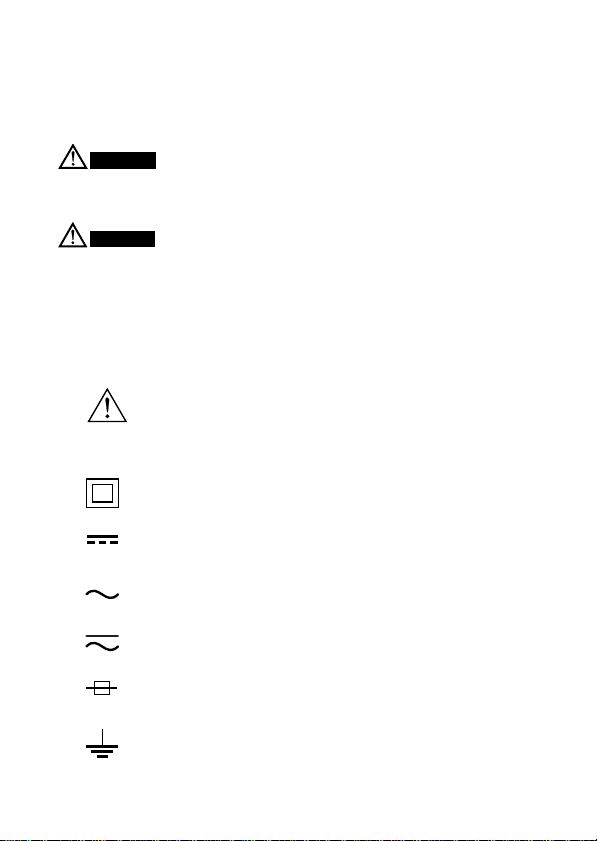
Danger! Handle with Care
This symbol indicates that the operator must refer to an
explanation in the instruction manual in order to avoid risk
of injury or death of personnel or damage to the instrument.
Double Insulation
This symbol indicates double insulation.
Direct Current
This symbol indicates DC voltage/current.
Alternating Current
This symbol indicates AC voltage/current.
DC/AC
This symbol indicates AC and DC.
Fuse
This symbol indicates a fuse.
Ground
This symbol indicates ground (earth).
ii
Page 5

WARNING
■ Always observe the following instructions. Failure to do so
may result in electric shock or other dangers that may lead to
serious injury or the loss of life.
Testing leads
• Use the probes supplied by Yokogawa M&C with this instrument.
• Do not use testing leads that have deteriorated or are defective.
• Disconnect testing leads from the circuit under test before opening the
casing to replace the batteries or for any other reason.
• Disconnect testing leads from the circuit under test before attaching/
detaching the testing leads to/from the instrument.
• Disconnect testing leads from the instrument before opening the casing to
replace the batteries or for any other reason.
Casing
• Do not use the instrument if there is any damage to the casing or when the
casing is removed.
Fuses
• Use fuses of the specified rating when the fuse is replaced.
Operating Environment
• Do not operate the instrument in an atmosphere where any flammable or
explosive gas is present.
• Avoid using the instrument if it has been exposed to rain or moisture or if
your hands are wet.
Disassembly
• No person, except personnel from Yokogawa M&C, is authorized to
disassemble this instrument.
iii
Page 6

WARNING
■ To avoid damage to instrument and/or electric shock
The restrictions on the maximum voltage level for which the 734 01 and
734 02 can be used, depend on the over-voltage categories specified by
the safety standards. These category specifications are set to protect
operators against transient impulse voltages and surge voltages in power
line.
Do not apply any input level higher than maximum allowable input.
AC/DC 600V CAT.III
AC/DC 1000V CAT.II
䊉 Over-voltage Category (Safety standards EN61010-1)
CAT.III: Covers the path from an indoor distribution switchboard to a
mains outlet.
CAT. II: Covers a primary-stage circuit of equipment connected to a
mains outlet.
CAT. I : Covers a secondary-stage circuit of power transformer of
equipment.
Note
Radiation immunity affects the accuracy of the 734 01 and 734 02 under
the conditions specified in EN5008-1 and EN61326-1.
Use of this instrument is limited to domestic, commercial, and light
industry applications. If equipment generating strong electromagnetic interference is located nearly, the instrument may malfunction.
iv
Page 7

Contents
1. Overview ................................................................................................ 1
2. Specifications ......................................................................................... 3
2-1 General Specifications .................................................................. 3
2-2 Measurement Ranges ................................................................... 6
3. Operation .............................................................................................. 14
3-1 Precautions Before Measurement ............................................... 14
3-2 Components ................................................................................ 15
3-3 Measuring Instruction ................................................................ 20
4. Battery and Fuse Replacement ............................................................. 42
4-1 Battery Replacement .................................................................. 42
4-2 Fuse Replacement ...................................................................... 43
5. Calibration and Maintenance................................................................ 44
v
Page 8

1. Overview
䊉 Fast and more accurate measurement
The 734 01 and 734 02 digital multimeters use Σ modulation for
A/D conversion, which enable fast and more accurate measurement.
䊉 Display
5-digit (LCD)
Maximum Reading: 50000
Bar graph indicator
䊉 Supports a variety of measurement function
DC Voltage, AC Voltage, DC Current, AC Current, Resistance, Frequency,
Temperature, Capacitor,
Duty cycle ratio, Decibel (dB), Averaging when the measured value may
greatly fluctuate,
Relative values from the reference measurement values (REL ),
Minimum value (MIN), Maximum value (MAX), Average value (AVG),
Range Hold (R•H), Data Hold (D•H), Auto Hold (A•H), Peak Hold* (P•H),
Continuity Check, Zero Adjustment (Capacitor, Resistance), Diode Test,
Save to Memory, LCD backlight*,
*: For model 734 02 only
䊉 Communication: Optional communication unit is required
• Enables downloading of measurement data to a personal computer
using optional communication package.
Uploading of data, making trend graph and downloading to EXCEL
are possible according to applications.
• Output of measurement data to the optional printer is possible.
1
Page 9

䊉 Safety design
Complied standards: CE standards
Uses a current-input terminal shutter for preventing wrong input.
Uses high-performance UL-standard fuses.
2
Page 10
2. Specifications
2-1 General Specifications
Function: DC Voltage, AC Voltage, DC Current, AC Current,
Resistance, Frequency, Temperature, Capacitor,
Duty cycle ratio, Decibel (dB), Averaging functuon,
Relative values from the reference measurement
values (REL ), Minimum value (MIN), Maximum
value (MAX), Average value (AVG), Range Hold
(R•H), Data Hold (D•H), Auto Hold (A•H), Peak
Hold* (P•H), Continuity Check, Zero Adjustment
(Capacitor, Resistance), Diode Test, Save to
Memory, LCD backlight*,
*: For model 734 02 only
Measuring method: Σ modulation
Display: 5-digit (LCD)
Maximum Reading: 50000
Polarity Indicator: “–” Appears automatically when
the polarity is negative
Overrange Indicator: “ OL ”
Low-battery Indicator: “ ” Appears when the
batteries become low
Measurement cycle: Digital display 3 times per second
When frequency measurement: one times per second
When capacitor measurement (50mF): max. 0.03
time per second
Bar graph display 10 times per second
3
Page 11

Operating temperature and humidity ranges:
-10 to 50ºC, 80%RH or less (no condensation)
70%RH or less at 40 to 50ºC.
Storage temperature and humidity ranges:
-25 to 60ºC, 70%RH or less (no condensation)
Temperature coefficient:(Accuracy at 23±5ºC× 0.05)/ºC or less
(Temperature ranges: -10 to 18ºC and 28 to 50ºC)
Operating altitude: 2000m max. above sea level
Power supply: AA-size (R6) 1.5V batteries: 2
Battery life: Approximately 120 hours
(Operating hours of alkaline batteries when in DC
voltage-mode.)
Note: The battery life varies depending on the
operating conditions.
Withstand voltage: 5.5kVrms AC for one minute
(across input terminals and casing)
External dimensions: Approximately 85(W)×191(H)×40(D)mm
Weight: Approximately 450g
Complied standards: Safety standards
EN61010-1; 1995, EN61010-2-031; 1995
Overvoltage category III (Max. input voltage:
AC/DC600V)
Overvoltage category II (Max. input voltage:
AC/DC1000V)
Pollution degree 2
EMC standards
EMI (Electro Magnetic Interference)
EN55011; 1998
EN61326-1; 1997+A1;1998
(Class B, Group 1)
4
Page 12

EMS (Immunity)
EN50082-1; 1997
EN61326-1; 1997+A1;1998
Effect of radiation immunity:
Accuracy range of reading:
[Rated accuracy +12% of maximum reading] for
the strength of a radio-frequency electromagnetic
field of 3V/m
Standard accessories: Instruction manual: 1
Testing leads: 1set
Batteries (included): 2
Fuse (included)
500mA/600V, 15A/600V
Optional accessories:
Communication package with communication cable
Engligh version 920 01-E
Package with RS-232C Cable 920 01-E/P
Temperature probes 7511 02 to 05
Carrying case
For the 734 main unit with testing leads
For the 734 main unit with testing leads
and communication cable 930 14
Fuse
500mA/600V A1518EF
15A/600V A1519EF
Testing leads (1set) RD031
Printer 97010
AC adapter (for printer, Europe) 940 06
AC adapter (for printer, USA) 940 07
Thermal paper for printer (10 rolls) 970 80
RS-232C Cable (for printer) 910 15
B9646HH
5
Page 13
2-2 Measurement Ranges
Test conditions:
Temperature and humidity: 23±5ºC at 80%RH or less
Accuracy: ±(percentage of reading + number of digits)
Note: Each response time is a value to rated accuracy within
selected range.
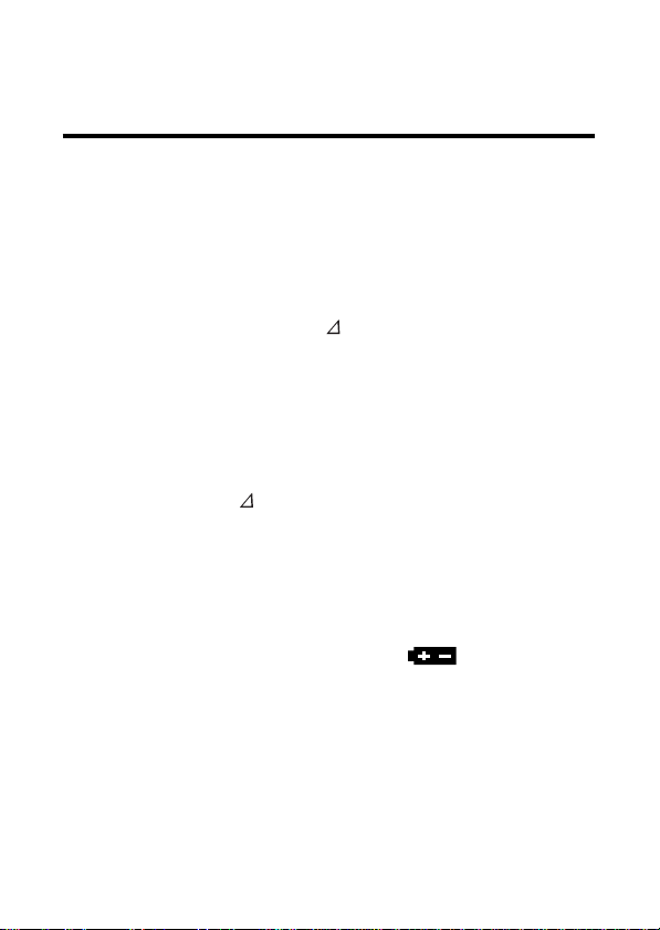
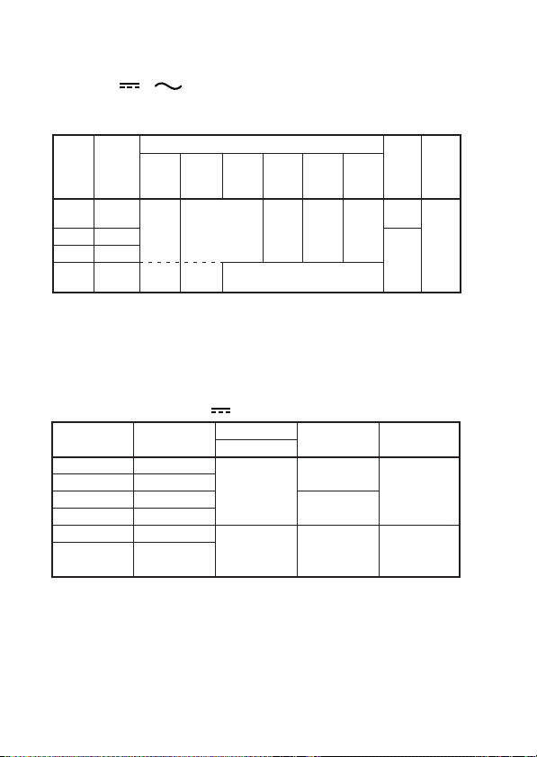
DC Voltage Measurement V
Range Resolution
50mV
0.001mV
*
500mV
2400mV
1000V
5V
50V
500V
0.01mV
0.1mV
0.0001V
0.001V
0.01V
0.1V
Accuracy
73401 73402
0.1+10
0.04+2
0.05+10
0.02+2
0.025+5
0.07+2
0.03+2
*: Maximum Reading of 2400mV Range: 24000
NMRR: 80dB or more 50/60Hz –0.1%
CMRR: 120dB or more 50/60Hz (Rs=1k‰)
Response time: 1 sec max.
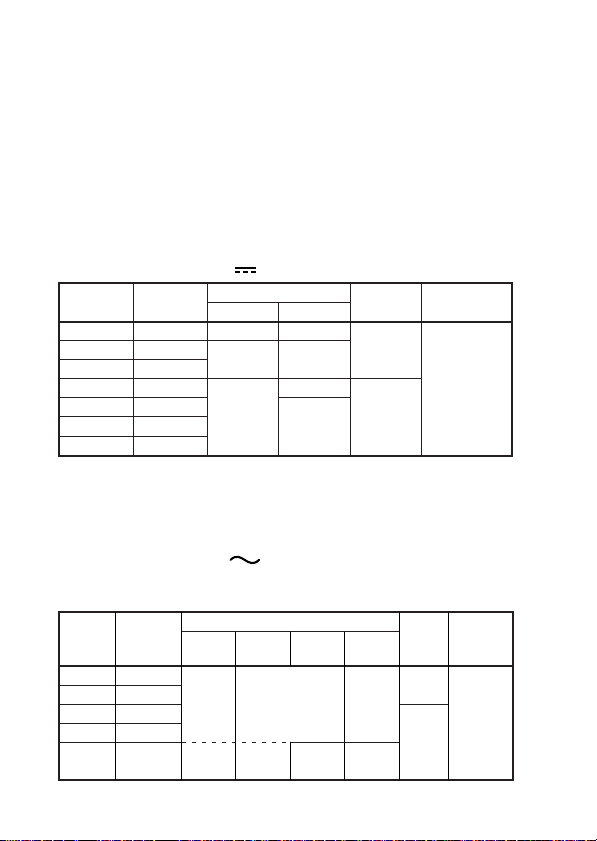
AC Voltage Measurement V
734 01
AC Coupling, Rms-value detection, Crest factor: <3
Accuracy
Resolution
Range
500mV
5V
50V
500V
1000V
0.01mV
0.0001V
0.001V
0.01V
0.1V
10 to
20Hz
1.5+30
*1
*2
20Hz to
1kHz
*2
1k to
10kHz
0.7+30
*1
3+30
6
*2
Input
Resistance
Approx.
100M‰
10M‰
Impe-
10k to
dance
20kHz
11MΩ
<50pF
2+50
*2
10MΩ
<50pF
---
Maximum
Input Voltage
1000V DC
1000V
rms AC
Maximum
Input
Volt age
1000V
rms AC
1000V
Input
DC
Page 14
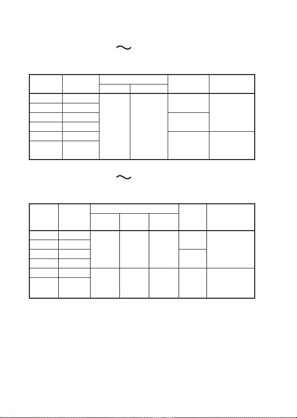
AC Voltage Measurement V
734 02
AC Coupling, Rms-value detection, Crest factor: <3
Range
500mV
5V
50V
500V
1000V
Resolution
0.01mV
0.0001V
0.001V
0.01V
0.1V
10 to
20Hz
1+30
*1
*2
20Hz to
1kHz
0.4+30
*2
Accuracy
1k to
10kHz
*1
3+30
*2
10k to
20kHz
1+40
*1
Accuracy
*1: At 5 to 100% of range
*2: At 10 to 100% of range
CMRR: 80dB or more DC to 60Hz (Rs=1kΩ)
Response time: 2 sec max.
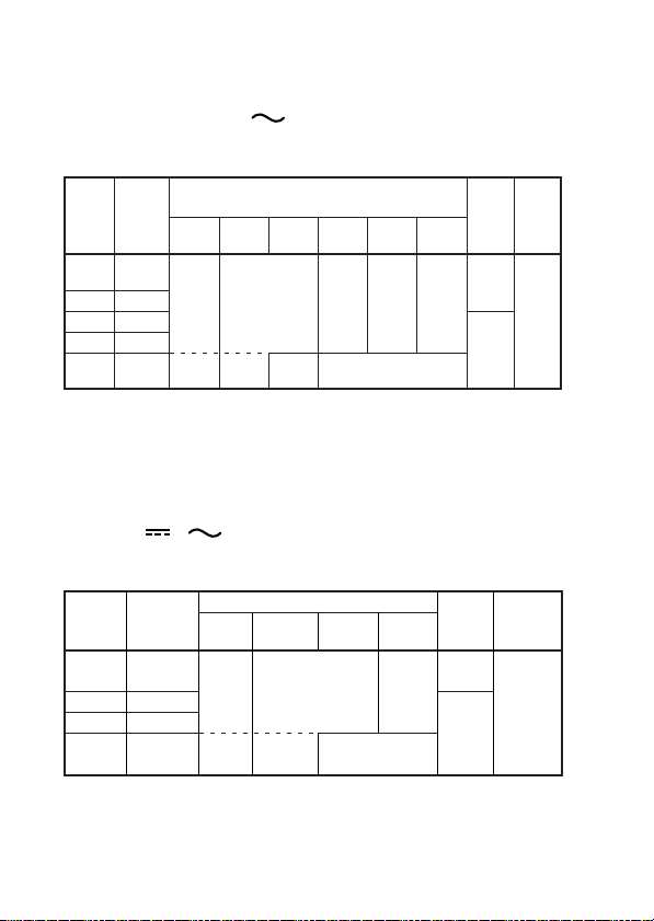
DCV+ACV +
734 01
Maximum Reading 5000, Crest factor: <3
Accuracy
Resolution
Range
5V
50V
500V
1000V
0.001V
0.01V
0.1V
1V
DC, 10
to 20Hz
1.5+10
DC, 20Hz
*1
*2
to 1kHz
1+10
*2
DC, 1k
to 10kHz
*1
20k to
50k to
50kHz
100kHz
2+70*25+200
*2
---
DC, 10k
to 20kHz
2+10
*2
---
Input
Impedance
11MΩ
<50pF
10MΩ
<50pF
Input
Impedance
11MΩ
<50pF
10MΩ
<50pF
Maximum
Maxi-
mum
Input
Voltage
1000V
rms
AC
1000V
DC
Input
Voltage
1000V
rms AC
1000V
DC
7
Page 15
DCV+ACV +
734 02
Maximum Reading 5000, Crest factor: <3
Range
5V
50V
500V
1000V
Resolution
0.001V
0.01V
0.1V
1V
DC,
10 to
20Hz
1.5+10
*1
*2
DC,
20Hz to
1kHz
0.5+10
*2
Accuracy
DC,
1k to
10kHz
*1
DC,
10k to
20kHz
1+10
*1
---
Accuracy
*1: At 5 to 100% of range
*2: At 10 to 100% of range
CMRR: 80dB or more DC to 60Hz (Rs=1kΩ)
Response time: Approx. 5 sec
DC Current Measurement A
Accuracy
73401/02
<0.11mV/µA
0.2+2
0.6+2
Range
500µA
5000µA
50mA
500mA
5A
10A
Resolution Voltage Drop
0.01µA
0.1µA
0.001mA
0.01mA
0.0001A
0.001A
Response time: 1 sec max.
DC,
DC,
20k to
50k to
50kHz
100kHz
2+10*25+20
<4mV/mA
<0.1V/A
Input
Impedance
11MΩ
<50pF
*2
10MΩ
<50pF
Maximum
Input Current
500mA
Protected by a
500mA/600V
fuse.
15A
Protected by a
15A/600V fuse.
Maxi-
mum
Input
Voltage
1000V
rms
AC
1000V
DC
8
Page 16
AC Current Measurement A
734 01
Range
Resolution
500µA
5000µA
50mA
500mA
AC Current Measurement A
734 02
5A
10A
0.001mA
0.0001A
0.01µA
0.1µA
0.01mA
0.001A
Accuracy
10 to 20Hz 20Hz to 1kHz
1.5+20 1+20
Voltage Drop
<4mV/mA
Accuracy
Resolution
Range
500µA
5000µA
50mA
500mA
5A
10A
0.01µA
0.1µA
0.001mA
0.01mA
0.0001A
0.001A
20Hz to
10 to
20Hz
1kHz
1+20
1.5+20 1+20 2+30
0.75
+20
1k to
5kHz
1+30
Model 734 01/02
Accuracy
At 5 to 100% of range
Note: At 10 to 100% of range for 10A Range
Response time: 2 sec max.
<0.11
mV/µA
<0.1V/A
Voltage
Drop
<0.11
mV/µA
<4
mV/mA
<0.1
V/A
Crest factor: <3
Maximum
Input Current
500mA
Protected by a
500mA/600V
fuse.
15A
Protected by a
15A/600V fuse.
Crest factor: <3
Maximum
Input Current
500mA
Protected by a
500mA/600V
fuse.
15A
Protected by a
15A/600V fuse.
9
Page 17

DCA+ACA +
734 01
Maximum Reading 5000, Crest factor: <3
Accuracy
ResolutionRange
500µA
5000µA
50mA
500mA
5A
10A
DCA+ACA +
734 02
0.01mA
0.1mA
0.001A
0.1µA
1µA
0.01A
DC, 10
to 20Hz
2+10
DC, 20Hz
to 1kHz
1.5+10
Accuracy
Resolution
Range
500µA
5000µA
50mA
500mA
5A
10A
0.01mA
0.001A
0.1µA
1µA
0.1mA
0.01A
DC, 10
to 20Hz
1.5+10
2+10
DC, 20Hz
to 1kHz
1.5+10
1+10
DC, 1k
to 5kHz
1.5+10
3+10
Model 734 01/02
Accuracy
At 5 to 100% of range
Note: At 10 to 100% of range for 10A Range
Response time: Approx. 5 sec
Voltage
Drop
<0.11
mV/µA
<4mV/mA
<0.1V/A
Volt age
Drop
<0.11
mV/µA
mV/mA
<0.1
V/A
Maximum
Input Current
500mA
Protected by a
500mA/600V
fuse.
15A
Protected by a
15A/600V fuse.
Crest factor: <3
Maximum
Input
Current
500mA
Protected by a
<4
500mA/600V
fuse.
15A
Protected by a
15A/600V fuse.
10
Page 18

Resistance Measurement Ω
Accuracy
Range
500Ω
5kΩ
50kΩ
500kΩ
5MΩ
50MΩ
Resolution
0.0001kΩ
0.001kΩ
0.0001MΩ
0.001MΩ
73401 73402
0.01Ω
0.1+2 0.05+2
0.01kΩ
0.5+2
Accuracy is specified after zero adjustment
1+2
(resistance).
Measuring
Current
<1mA
<0.25mA
<25µA
<2.5µA
<1.5µA
<0.13µA
Open-loop
Voltage
Input
Protective
Voltage
<2.5V 600V rms
Response time: 3 sec max. at 500Ω to 500kΩ
10 sec max. at 5MΩ to 50MΩ
Continuity Check
Maximum Reading 5000
Range
Resolution
500Ω 0.1Ω
Diode Test
Range of Operation
The buzzer turns on for
resistances lower than
100±50Ω.
Measuring
Current
Approx.
0.5mA
Measuring
Range Resolution
Accuracy
Current
(Vf=0.6V)
2.4V 0.0001V
1+2
Approx.
0.5mA
11
Open-loop
Open-loop
Voltage
Volt age
<5V
Protective
600V rms
Protective
Voltage
<5V 600V rms
Input
Volt age
Input
Page 19

Temperature Measurement TEMP
Range Resolution Accuracy
-50 to 800˚C 0.1˚C 1+1.5˚C
-58 to 1472˚F 0.1˚F 1+3.0˚F
Use optional Temperature Orobe: Thermocouple Type K
Capacitor Measurement
Range
5nF
50nF
500nF
5µF
50µF
500µF
5mF
50mF
Resolution Accuracy
0.001nF
0.01nF
0.1nF
1+5
0.001µF
0.01µF
0.1µF
0.001mF
0.01mF
2+5
3+5
Accuracy is specified after zero adjustment
(capacitor).
Frequency Measurement Hz
AC Coupling, Maximum Reading 9999
Input Protective
Voltage
600V rms
Input Protective
Voltage
600V rms
Range (AUTO)
2.000 to 9.999Hz
9.00 to 99.99Hz
90.0 to 999.9Hz
900 to 9999Hz
9.00 to 99.99kHz
0.001Hz
0.01Hz
0.1Hz
1Hz
0.01kHz
Accuracy
*1: At 10 to 100% of input voltage or current range
*2: At 40 to 100% of input voltage or current range
12
AccuracyResolution
0.02+1
*1
*2
Page 20

Duty cycle ratio Hz
Range Resolution Accuracy
10 to 90% 1% ±1%*
Accuracy
*: At 10.00Hz to 500.0Hz, square wave
At 40 to 100% of input voltage or current range
Peak Hold P•H
Maximum Reading 5000
Range Accuracy
DCV, DCA ±100 digit >1msec
Response Time
Maximum
13
Page 21

3. Operation
3-1 Precautions Before Measurement
■ Examining Items Contained in the Package
After opening the package, be sure to examine the product as instructed
below before use. Should the delivered product be the wrong model, lack
any item, or show any flaw in its appearance, contact the vendor from
which you purchased the product.
■ Precautions of Operation and Storage
CAUTION
• The instrument is shipped with batteries included ready for use after
unpacking.
(The batteries, therefor, may not last their full specified life.)
• Do not use the instrument near noise-emitting equipment or
where there may be a sudden change of temperature. Otherwise, the
instrument may give an unstable reading or errors.
Removal of Dirt
Do not wipe the instrument using any volatile such as benzine or
paint thinner, as this may damage or discolor the front panel.
Use a dry cloth to clean the instrument.
Storage Conditions
• Do not leave the instrument exposed to direct sunlight or in a hot
and humid location such as the inside of a vehicle, for any prolonged
length of time.
• If the instrument will not be used for a prolonged period,
remove the batteries.
14
Page 22

3-2 Components
■ Panel Description
Display (LCD)
SELECT (PRINT) key
RANGE key
HOLD (SAVE) key
5000 (READ) key
(For Model 734 01)
LIGHT (READ) key
(For Model 734 02)
REL /% key
MIN/MAX (LOG) key
MEMORY key
Function switch
Input terminal block
15
Page 23

1) Function switch
Turns off the power or select the measurement mode (function).
Turns off the power.
OFF
AC voltage (V) measurement
V
AC voltage (mV) measurement
mV
DC voltage (V) measurement
V
DC voltage (mV) measurement
mV
Continuity check, Diode Test
2) SELECT key
Pressing this key in each measurement modes (function)
described above selects other measurement modes (function).
V, mV 1 HzV: Frequency measurement
2Hz%: Frequency measurement
3dBV: dB measurement
4dBm : dBm measurement
V + (DC+AC) measurement
Ω ZERO CAL: Zero Adjustment of Resistance
measurement
Diode Test
ZERO CAL: Zero Adjustment of Capacitor
measurement
µA/mA/A 1 : AC voltage measurement
2 + : (DC+AC) measurement
3Hz%: Frequency measurement
Ω
Resistance measurement
Capacitor measurement
TEMP
Temperature measurement
µA
mA
DC/AC current measurement
A
(Voltage value is displayed.)
(Duty cycle ratio)
(Voltage vaë e is displayed.)
(Duty cycle ratio)
16
Page 24

3) RANGE key
Allows the operator to select the measuring range.
Fixed ranges : The display shows the “ R•H ” symbol.
The range increases every time this key is pressed.
AUTO range : The display shows the “ AUTO ” symbol.
To return to the auto-ranging mode, hold down
this key for more than one second.
4) HOLD key
Selects between the DATA HOLD, AUTO HOLD and PEAK HOLD
functions. To cancel functions, press this key once again.
DATA HOLD: Holds the display readings.
The display shows the “ D•H ” symbol.
AUTO HOLD: Holds the measured value when the testing leads are
handled.
The display shows the “ A•H ” symbol.
PEAK HOLD: Holds the peak value.
The display shows the “ P•H ” symbol. (For Model
734 02)
5) 5000 key (For Model 734 01), LIGHT key (For Model 734 02)
5000 key: Used to select 3.5-digit display.
Press this key once again to display 5-digit.
LIGHT key: Use to turn on the LCD backlight.
Press this key once to turn on the LCD backlight for
approximately one minute.
The LCD backlight is lit for approximately one minute.
(To postpone turned on time, press this key once again.)
To cancel the function, hold down this key for more than
one second.
Enables switching 3.5-digit display and 5-digit display.
To execute the above, please use Additional functions simply set
when POWER ON.
17
Page 25

6) REL ∆ / % key
The instrument can calculate relative values or differences, and percentage
values from the reference measurement values.
1 : Relative Calculation
The display shows the “ REL ” symbol.
The sub-display shows the reference voltage value.
2 : Percentage Calculation
The display shows the “ % ” symbol.
The sub-display shows the reference voltage value.
7) MIN/MAX key
Displays the minimum value (MIN), maximum value (MAX) and average
value (AVG) during measurement.
Pressing this key starts recording and at the same time the display shows
MIN/MAX/AVG to release AUTO POWER OFF.
8) MEMORY key
Data can be stored in internal memory using this key.
Used when outputting to printer with the optional communication package.
■ Display (LCD) Description
18
Page 26

Symbol and Unit Description
Appears when in DC-mode measurement
Appears when in AC-mode measurement
+
–
Appears when in DC+AC-mode measurement
Appears when the polarity is negative
Appears when in diode test
Appears when in continuity check
Relative calculation indicator
R•H
AUTO
Fixed ranges indicator
AUTO range indicator
DATA HOLD indicator
AUTO HOLD indicator
PEAK HOLD indicator
Lit when in MIN/MAX/AVG-mode
Lit when in MIN/MAX/AVG-mode
Lit when in MIN/MAX/AVG-mode
AUTO OFF
nF, µF, mF
mV , V
µA, mA, A
MΩ, kΩ, Ω
˚C (˚F)
kHz, Hz
dB, dBm
% (Main-display)
% (Sub- display)
(Sub- display)
mV , V
s (Sub- display)
Auto power off indicator
Unit for capacitance measurement
Unit for voltage measurement
Unit for current measurement
Unit for resistance measurement
Unit for temperature measurement
Unit for frequency measurement
Decibel calculation indicator
Unit for percentage calculation
Unit for duty cycle ratio calculation
Unit for voltage measurement (dB
Unit for recording time when in MIN/MAX/AVG-mode
Recording time indicator when in MIN/MAX/AVG-mode
(Sub- display)
Number of saved data indicator
Reference value indicator when relative calculation
Duty cycle ratio indicator
Voltage value (dB
V
, HzV) indicator
Reference resistance value (dBm) indicator
Appears when the batteries become low
Bar graph indicator, Range indicator
V
, HzV)
19
Page 27

3-3 Measuring Instructions
WARNING
To avoid damage to instrument or equipment
• Before starting measurement, make sure that the position of function switch
and the input terminals for connecting the testing leads are appropriate for
the desired mode of measurement.
• Temporarily remove the testing leads from the device under test before
operating the function switch.
● AC Voltage Measurement ( V, mV)
1) Turn the function switch to the “ V ” or “ mV ” position.
2) Plug the black testing lead into the “ COM ” input terminal and the red
testing lead into the “ • V • Ω • • TEMP ” input terminal.
3) Connect the testing leads to the circuit under test and then read the value
when it stabilizes.
● DC Voltage Measurement ( V, mV)
1) Turn the function switch to the “ V ”or “ mV” position.
2) Plug the black testing lead into the “ COM ” input terminal and the red
testing lead into the “ • V • Ω • • TEMP ” input terminal.
3) Connect the testing leads to the circuit under test and then read the value
when it stabilizes.
Note
If “ mV ”range is selected and the testing leads are left open-circuited,
the instrument may give a certain reading. This dose not affect your
measurement.
20
Page 28

● DC+AC Voltage Measurement ( + )
1) Turn the function switch to the “ V ” position.
2) Press the SELECT key to select DC+AC voltage measurement.
(The display shows the “ + ” symbol.)
3) Plug the black testing lead into the “ COM ” input terminal and
the red testing lead into the “ • V • Ω • • TEMP ” input terminal.
4) Connect the testing leads to the circuit under test and then read
the value when it stabilizes.
● Resistance Measurement (Ω)
CAUTION
To avoid damage to instrument
Turn off the power to the circuit under test before starting measurement in
order to prevent any excessive voltage from being applied to the instrument.
1) Turn the function switch to the “Ω ” position.
2) Plug the black testing lead into the “ COM ” input terminal and the red
testing lead into the “ • V • Ω • • TEMP ” input terminal.
3) Connect the testing leads to the circuit under test and then read the value
when it stabilizes.
Note
Zero adjustment
Zero adjustment is recommended for correct measurement. After
executing 1), 2) above, short the two testing leads. Press the SELECT
key for adjust. (The display shows the “0.0Ω” value.) The value stores
till turn off.
21
Page 29

● Continuity Check ( )
CAUTION
To avoid damage to instrument
Turn off the power to the circuit under test before starting measurement in
order to prevent any excessive voltage from being applied to the instrument.
1) Turn the function switch to the “ ” position.
2) Plug the black testing lead into the “ COM ” input terminal and the red
testing lead into the “ • V • Ω • • TEMP ” input terminal.
3) Connect the testing leads to the circuit under test. If the circuit is continuous
(no more than approximately 100Ω), the buzzer sounds.
● Diode Test ( )
CAUTION
To avoid damage to instrument
Turn off the power to the circuit under test before starting measurement in
order to prevent any excessive voltage from being applied to the instrument.
1) Turn the function switch to the “ • ” position.
Press the SELECT key to select Diode test.
2) Plug the black testing lead into the “ COM ” input terminal and the red
testing lead into the “ • V • Ω • • TEMP ” input terminal.
3) Connect the testing leads to the diode and then read the value when it
stabilizes.
22
Page 30

<Forward-bias Diode Test>
Connect the black testing lead to the cathode and the red testing lead to the
anode.
Silicon diodes should give a reading of approximately 0.5V and light-emitting
diodes a reading between approximately 1.5V and 2.0V.
<Reverse-bias Diode Test>
Connect the black testing lead to the anode and the red testing lead to the
cathode.
Normally, the display shows the “ OL ” symbol, indicating that the diode
under test is normal. The diode is defective if the display gives a certain
voltage level.
Black testing
lead
Red testing
lead
Red testing
lead
Black testing
lead
Figure 1 Forward-bias
Diode Test
Figure 2 Reverse-bias
Diode Test
● Temperature Measurement (TEMP)
CAUTION
To avoid damage to instrument
Turn off the power to the circuit under test before starting measurement in
order to prevent any excessive voltage from being applied to the instrument.
23
Page 31

Note
Optional Temperature probe is required for temperature measurement.
Temperature Probe: Thermocouple Type K
Model: 7511 02 to 05
1) Turn the function switch to the “ TEMP ” position.
2) Plug the black terminal of measuring probe into the “ COM ” input terminal
and the red terminal of measuring probe into the “ • V • Ω • •
TEMP ” input terminal.
3) Contact the measuring probe to the under test and then read the value
when it stabilizes.
To switch temperature units
Displaying “ ºC ” only is configured at factory before shipment. Carry out
the following setting procedure to display “ ºF ”. While pressing the
SELECT, RANGE and HOLD key simultaneously, turn the function
switch to the “ TEMP ” position. Next time pressing the SELECT key,
the temperature unit switches from ºC to ºF.
● Current Measurement ( µA/mA/A)
WARNING
To avoid damage to instrument or equipment
Before starting measurement, make sure that the position of function switch
and the input terminals for connecting the testing leads are appropriate for
the desired mode of measurement.
1) Turn the function switch to the “µA ” , “mA ” or “A ”position.
(If the magnitude of the current being measured is not known, select the
“A ”position. Make sure the current being measured is no more than 0.5A
before the “µA ” or “mA ” position is selected.)
24
Page 32

2) Please select between DC and AC. When selecting AC, press the SELECT
key.
3) Plug the black testing lead into the “ COM ” input terminal and the red
testing lead into the “A ”input terminal.
If the current is in the order of mA or less, plug the red testing lead into the
“µA • mA” input terminal.
4) Connect the testing leads to the circuit under test and then read
the value when it stabilizes.
● DC+AC Current Measurement ( + )
WARNING
To avoid damage to instrument or equipment
Before starting measurement, make sure that the position of function switch
and the input terminals for connecting the testing leads are appropriate for
the desired mode of measurement.
1) Turn the function switch to the “µA” , “mA” or “A” position.
(If the magnitude of the current being measured is not known, select the
“A” position. Make sure the current being measured is no more than 0.5A
before the “µA” or “mA” position is selected.)
2) Press the SELECT key to select the DC +AC measurement.
(The display shows the + symbol.)
Plug the black testing lead into the “ COM ” input terminal and
the red testing lead into the “A” input terminal.
If the current is in the order of mA or less, plug the red testing lead
into the “µA • mA” input terminal.
3) Connect the testing leads to the circuit under test and then read the value
when it stabilizes.
25
Page 33

● Capacitor Measurement ( )
CAUTION
To avoid damage to instrument
• Turn off the power to the circuit under test before starting measurement in
order to prevent any excessive voltage from being applied to the instrument.
• Before starting measurement, be sure to discharge the capacitor under
check.
1) Turn the function switch to the “ ”position.
2) Plug the black testing lead into the “ COM ” input terminal and
the red testing lead into the “ • V • Ω • • TEMP ” input terminal.
3) Open the testing lead and press the SELECT key in 5nF range to adjust
the capacitance to zero. (The display shows “ 0.000 ”.)
4) Connect the testing leads to the circuit under test and then read the value
when it stabilizes.
Note
When the capacitor check is below the capacity at zero calibration,
“0.00” is displayed until the power off.
● Frequency Measurement (Hz), Duty cycle ratio (Hz)
CAUTION
To avoid damage to instrument
Turn off the power to the circuit under test before starting measurement in
order to prevent any excessive voltage from being applied to the instrument.
26
Page 34

1) Turn the function switch to the voltage( V, mV) or the current(µA,
mA, A )position.
2) Press the SELECT key to select the range of frequency. (The display shows
the unit of frequency.)
3) Plug the black testing lead into the “ COM ” input terminal.
Plug the red testing lead into the “ • V • Ω • • TEMP ” input
terminal when voltage measurement.
Plug the red testing lead into the suitable input terminal (“ A” or “µA•mA”)
for current value when current measurement.
4) Contact the measuring probe to the under test and then read the value
when it stabilizes. The display shows frequency value in main-display
and duty cycle ratio value in sub-display.
● AUTO HOLD Function
The instrument can automatically retain the measured value
when the testing leads are handled as described below.
1) Press the HOLD key to select u ûêAuto hold function.
(The display shows the“ A•H ” symbol.)
2) Connect the testing leads to the circuit under test.
3) When the reading stabilized, the buzzer sounds.
4) Remove the testing leads from the circuit under test.
5) The display shows the measured value that is retained.
You can repeat steps 2) to 4)as many times as you like as long as the
display shows the “ A•H ” symbol.
Note
• In DC/AC voltage measurement, the Auto hold function is only available
for ranges greater than the 5V range.
• This function is not available for Temperature, Capacitor and Frequency
measurement.
• The Auto hold function can not be applied to unstable signals.
27
Page 35

● PEAK HOLD Function
This instrument can always detect, update and display the peak value
(instantaneous) in DCV and DCA measurement. The peak value of the wave
can be seen.
1) Turn the function switch to DCV or DCA position.
2) Connect the testing leads to the circuit under test.
3)Press the HOLD key to select Peak Hold. (The display shows the “ P•H ”
symbol.)
4) The display shows the peak value.
5) When resetting the peak value in HOLD, press the MIN/MAX key.
Then new peak value can be in HOLD.
Note
Even though the input signals (DCV, DCA) have negative polarity,
the peak value can be measured when the peak is in the positive direction.
1) Press the REL /% key to relative calculation in PEAK HOLD mode.
The display shows the “ ” symbol and the relative peak value.
2) Press the REL /% key to percentage calculation.
The display shows the “ % ” symbol and the percentage peak value.
SEE ALSO
Next section “ Relative and percentage calculation”
When resetting the peak value, press the MIN/MAX key.
Then new peak value can be in HOLD.
To cancel the percentage calculation, Press the REL /% key again.
“ % ” symbol disappears, then retrieves the PEAK HOLD mode.
28
Page 36

● Relative and percentage calculation
The instrument can calculate relative values or difference, and percentage
values from the reference measurement values. (The range will be fixed.)
<Relative (REL) calculation>
Subtracts the reference value from the measured value to display the relative
value or difference.
1) Enter the reference value.
2) Press the REL /% key.
(The display shows the“ ” symbol and the sub-display shows the
reference value.)
3) Enter the measured value.
The display shows the relative value or difference.
<Percentage (%) calculation>
Calculates and display the percentage value according to the following
equation: % value =(measured value – reference value)/reference value
1) Enter the reference value.
2) Press the REL /% key.
(The display shows the“ ” symbol and the sub-display shows the
reference value.)
3) Enter the measured value.
Press the REL /% key again. (The display shows the“ % ” symbol.)
● Decibel calculation (dBm, dBV)
The instrument can perform logarithmic calculations on a AC voltage.
dBm : 20log
Measured voltage value
Reference resistance value
× 10
3
(1mW/Reference resistance (Ω)=0dBm)
29
Page 37

dBV: 20log
1) Turn the function switch to the V or mV position.
2) Press the SELECT key to select dBm dBV .
(The display shows the “ dBm ”, “ dB ” symbol.)
3) Connect the testing leads to the circuit under test and then read
the value when it stabilizes.
4) When calculating relative value, press the REL /% key.
Measured voltage value
1(V)
Note
The instrument can switch (select) reference resistance value when measuring
dBm.
The reference resistance value is switched as follows every time the RANGE
key is pressed. (Shown in sub-display.)
Reference resistance value:
4,8,16,32,50,75,93,110,125,135,150
200,250,300,500,600,800,900,1000,1200
Default value: 600Ω
● MIN/MAX/AVG Function
The minimum value (MIN), maximum value (MAX) and average value
(AVG) during measurement are shown. The average value is shown by
dividing the integrated record data by the number of recording times.
Pressing this key starts recording and at the same time the display shows
“MIN”, “MAX” and “AVG” to release AUTO POWER OFF.
<Recording time>
The timer is activated to show the elapsed time from the start and
simultaneously the renewed time for MIN/MAX is also recorded.
30
Page 38

The elapsed time is displayed as follows:
0 sec. to 99 min. and 59 sec.: steps of 1 sec.
100 min. or more: steps of 1 min.
Press the HOLD key to stop recording. (The display shows the “ D•H ”
symbol.)
<To confirm the recording time>
For confirming the recording time, press the MIN/MAX key.
Subsequent pressing of this key repeats to display the present
minimum value (MIN), maximum value (MAX) and average value (AVG).
Press the HOLD key once again to restart recording.
Note
• No influence is exerted on the recorded data even if the test leads are
disconnected while the recording is stopped.
• If overload is recorded, the MIN or MAX display changes to “ OL ” display,
resulting in incorrect average data.
• For widely varying signal measurement, set the appropriate range in
which the MAX or MIN does not change to “ OL ” display.
● Memory Function
<To save a Data in internal memory>
The instrument can save a data using with the following two types of
modes.
SAVE-mode: Saves a data for one measurement
by manual operation.
LOGGING-mode: Automatically saves a data from
the start of logging.
Memory capacity
SAVE-mode: 50 data
LOGGING-mode: one time (600 data)
31
Page 39

Number of saved data
Number of saved data is 3-digit numbers. When LOGGING-mode,
“ L ” is attached to the top of 3-digit numbers. The instrument
allocates the smallest number, between 000 to 999, that has not yet
been used. Use the (RANGE) key or (REL /%) key switches
the number of saved data.
To save a Data (SAVE-mode)
1) Press the MEMORY key. (The display shows the “ MEM ”symbol.)
2) Press the SAVE (HOLD) key.
(The display shows the number of saved data.)
3) Press the SAVE (HOLD) key to save the data.
Another press of the SAVE (HOLD) key saves a data for the second time
measurement or later.
4) To cancel the function, hold down the MEMORY key for one second.
(“ MEM ” symbol disappears.)
To save a Data (LOGGING-mode)
1) Press the MEMORY key. (The display shows the “ MEM ”symbol.)
2) Press the LOG (MIN/MAX) key.
(The display shows the logging interval (period).)
Set the value with the (RANGE) key or (REL /%) key.
The default setting is one second.
The display shows “ FULL ” when the logging data is already saved.
When saving the new data, perform delete of data.
3) Press the LOG (MIN/MAX) key to start logging. (The “ MEM ”symbol is
flashing.)
4) To cancel the function, hold down the MEMORY key for one second.
When memory capacity becomes full, the function is automatically
canceled.
(“ MEM ” symbol disappears.)
32
Page 40

Note
LOGGING-mode operation during HOLD-mode disables HOLD-mode.
To load a Data (SAVE-mode)
1) Press the MEMORY key. (The display shows the “ MEM ”symbol.)
2) Press the READ (5000/ LIGHT*) key.
3) Press the SAVE (HOLD) key to select the number of saved data.
Select the number with the (RANGE) key or (REL /%) key.
4) To cancel the function, hold down the MEMORY key for one second.
(“ MEM ” symbol disappears.)
To load a Data (LOGGING-mode)
1) Press the MEMORY key. (The display shows the “ MEM ”symbol.)
2) Press the READ (5000/ LIGHT*) key.
3) Press the LOG (MIN/MAX) key to select the number of saved data.
Select the number with the (RANGE) key or (REL /%) key.
4) To cancel the function, hold down the MEMORY key for one second.
(“ MEM ” symbol disappears.)
<To delete of saving data>
Delete method (SAVE-mode)
• To delete all data
1) Press the MEMORY key.
(The display shows the “ MEM ”symbol.)
2) Hold down the SAVE (HOLD) key for one second.
(The display shows the “ CLr ”symbol.)
3) Press the SAVE (HOLD) key.
All data is deleted.
33
Page 41

• To overwrite (delete) selected data
1) Press the MEMORY key.
(The display shows the “ MEM ”symbol.)
2) Press the SAVE (HOLD) key.
(The sub-display shows the number of saved data.)
3) Use the (RANGE) key or (REL /%) key to select the number of
saved data.
4) Press the SAVE (HOLD) key to save the data.
5) To cancel the function, hold down the MEMORY key for one second.
(“MEM” symbol disappears.)
Delete method (LOGGING-mode)
• To delete all data
1) Press the MEMORY key.
(The display shows the “ MEM ”symbol.)
2) Hold down the LOG (MIN/MAX) key for one second.
(The display shows the “ CLr ”symbol.)
3) Press the LOG (MIN/MAX) key.
All data is deleted.
● AUTO POWER OFF Function
<To use the AUTO POWER OFF function>
The display shows the “ AUTO OFF ”indication.
• The instrument automatically turns off if no key is pressed for a period of
20 minutes.
The instrument will beep for approximately 30 seconds to alert the operator
before the AUTO POWER OFF function takes effect.
• Pressing any key or switch while the instrument is beeping postpones the
power-off time.
• Turning the function switch once after the power to the instrument is
automatically turned off switches the instrument on again.
34
Page 42

<To cancel the AUTO POWER OFF function>
1) Turn the function switch to the OFF.
2) With pressing the HOLD key, turn the function switch to the desired
position of any measurement mode (function).
The “ AUTO OFF ” indication turns off when the function is canceled.
Note
Additional functions simply set when POWER ON can be used.
<To enable the AUTO POWER OFF function once again>
1) Turn the function switch to the OFF.
2) Turn the function switch to the desired position of any measurement mode
(function).
The AUTO POWER OFF function is enabled again.
The display shows the “ AUTO OFF ” indication.
CAUTION
To avoid damage to instrument
When the measurement function is completed, turn the function switch back
to the OFF position to turn off.
● Additional functions simply set when POWER ON
With pressing the following keys, turn the function switch to the desired
position of any measurement mode (POWER ON-state).
This enables the following functions corresponding to the press keys.
35
Page 43

Keys Functions to be set
MIN/MAX
RANGE
SELECT
HOLD
HOLD + REL /%
SELECT + RANGE
● Averaging Function
The measured value may greatly fluctuate, the instrument can calculate the
average (8 times / approx. 2.4 seconds).
This function is available for Voltage, Current and Resistance-mode
measurement.
Averaging Function (calculates the average of
8 times)
5000 (3.5-digit display) For 734 02 only
LCD check (Lit only while pressing the
SELECT key)
Cancels the Auto power off function
Reset all calibration values to those before
shipment.
Calibration function
Note
Additional functions simply set when POWER ON can be used.
● 5000 display mode (734 01)
This function switches 3.5-digit display (5000) and 5-digit display (50000).
The function is not available for Capacitor, Temperature, DC+AC, Continuity
and Frequency-mode measurement.
Note
Additional functions simply set when POWER ON can be used.
● LCD Check
The instrument can lit all segments and mark for LCD check.
Additional functions simply set when POWER ON can used.
(Lit only while pressing the SELECT key.)
36
Page 44

● User Calibration Function
It is recommended that the instrument be calibrated periodically.
The instrument can be calibrated.
CAUTION
To avoid electrical shock
• Only authorized engineers are allowed to calibrate the instrument
using dedicated facilities.
• Connect the calibrator to the instrument with the calibrator’s testing leads.
• Before carrying out calibration, read the instruction manual of the calibrator.
• Temporarily remove the testing leads from the instrument before switching
measurement mode (function).
<Conditions of calibration>
Calibrator: With accuracy higher than of this instrument
Ambient Environment:
Temperature: 23±3ºC
Humidity: 55%RH or less
Leave the instrument for 30 minutes under above conditions
before carrying out calibration.
After reference valve of Calibrator stabilizes, Press the key to confirm for
calibration valve.
37
Page 45

<Table 1>
Carry out calibration of ranges in accordance with Table 1.
Calibration for 2 points (Input 1 and Input 2) is required other than DC
range.
After Input 1, carry out calibration of Input 2 repeating steps 6) and 7).
For AC voltage and AC current ranges (marked with ), calibration is
carried out at 50Hz frequency.
1) Turn the function switch from the OFF position to the mV position
while pressing the SELECT and RANGE keys at the same time.
The display shows the “ CAL ” symbol then the “ PASS ” symbol.
2) Press the SELECT key. (The display shows the “ - ” symbol.)
3) Press the HOLD key twice. (The display shows the “ - - - ” symbol.)
4) Press the RANGE key. (The display shows the “ mV ” symbol.)
5) Connect the instrument to the calibrator with the testing leads.
6) Set the calibrator to Input 1 value as an input to the instrument.
7) Press the HOLD key.
8) Be sure to confirm that the function switch and input terminal are set to
the desired range.
Carry out calibration of other ranges by repeating steps 6) and 7).
9) To quit calibration, turn the function switch back to the OFF position.
38
Page 46

DC 50mV
DC 500mV
DC 2400mV
DC 5V
DC 50V
DC 500V
DC 1000V
䊊
AC 500mV
䊊
AC 5V
䊊
AC 50V
䊊
AC 500V
䊊
AC 1000V
500‰
5k‰
50k‰
500k‰
5M‰
50M‰
Continuity Check ( )
DC 500 A
DC 5000 A
DC 50mA
DC 500mA
DC 5A
DC 10A
䊊
AC 500 A
䊊
AC 5000 A
䊊
AC 50mA
䊊
AC 500mA
䊊
AC 5A
䊊
AC 10A
Table 1. Input Signal for Calibration
Input 1 Input 2 UnitRange
50.000
500.00
2000.0
5.0000
50.000
500.00
1000.0
50.00
0.5000
50Hz
5.000
50.00
100.0
0.00
0.0000
0.000
0.00
0.0000
0.000
0.0
500.00
5000.0
50.000
500.00
5.0000
10.000
50.00
500.0
50Hz
5.000
50.00
0.5000
1.000
----
----
----
----
----
----
----
500.00
5.0000
50.000
500.00
1000.0
500.00
5.0000
50.000
500.00
5.0000
30.000
500.0
----
----
----
----
----
----
500.00
5000.0
50.000
500.00
5.0000
10.000
mV
mV
mV
V
V
V
V
mV
V
V
V
V
‰
k‰
k‰
k‰
M‰
M‰
‰
A
A
mA
mA
A
A
A
A
mA
mA
A
A
39
Page 47

<Table 2>
After completing the calibration for ranges in Table 1, carry out
calibration for “ Frequency Characteristic”.
The calibration for is frequency characteristic required for AC voltage
and AC current ranges (marked with ).
Calibration is carried out at the designated frequency in table 2.
1) Set the calibrator to Input value as an input to the instrument.
2) Press the MEMORY key.
3) After 20 seconds, buzzer sounds and the instrument confirm calibration.
(Do not next key operation till buzzer sounds.)
Table 2. Input Signal for Calibration
AC 500mV
䊊
䊊
AC 5V
䊊
AC 50V
䊊
AC 500V
䊊
AC 1000V
䊊
AC 500µA
䊊
AC 5000µA
䊊
AC 50mA
䊊
AC 500mA
䊊
AC 5A
䊊
AC 10A
5kHz
1kHz(400Hz)
1kHz
Input UnitRange
500.00
5.0000
50.000
500.00
1000.0
500.00
5000.0
50.000
500.00
5.0000
10.000
mV
V
V
V
V
µA
µA
mA
mA
A
A
40
Page 48

● Calibration of Capacitor Range
Before start calibration of the Capacitor range,
turn the function switch back to the OFF position.
1) Turn the function switch from the OFF position to the (Capacitor)
position while pressing the SELECT and RANGE keys at the same time.
The display shows the “ CAL ” symbol then the “ PASS ” symbol.
2) Press the SELECT key. (The display shows the “ - ” symbol.)
3) Press the HOLD key twice. (The display shows the “ - - - ” symbol.)
4) Press the RANGE key. (The display shows the “ nF ” symbol.)
5) Connect the instrument to the calibrator with the testing leads.
6) Set the calibrator to Input 1 value as an input to the instrument.
7) Press the HOLD key to confirm.
8) Set the calibrator to Input 2 value as an input to the instrument.
9) Press the HOLD key to confirm.
10) Carry out calibration of other ranges by repeating steps 6) to 9).
11) To quit calibration, turn the function switch back to the OFF position.
5nF
50nF
500nF
5µF
50µF
500µF
5mF
50mF
Input 1 Input 2 UnitRange
0.500
5.00
50.0
0.500
5.00
50.0
0.500
5.00
5.000
50.00
500.0
5.000
50.00
500.0
5.000
40.00
nF
nF
nF
µF
µF
µF
mF
mF
41
Page 49

4. Battery and Fuse Replacement
4-1 Battery Replacement
If the batteries fall below the normal operating voltage, the “ ”symbol
turns on.
Follow the steps below to replace the batteries with new ones.
(AA-size (R6) 1.5V batteries)
WARNING
Be sure to disconnect the instrument from the circuit under test and testing
leads before replacing the batteries.
CAUTION
• Do not mix batteries of different types or new batteries with used ones.
• Make sure the polarities of the new batteries are exactly as shown on the
battery holder.
To replace the batteries:
1) Remove the four screws on the back of the casing.
2) Open the casing.
3) Take the battery holder out of the casing.
4) Replace the batteries with new ones and
install the battery holder back into the
casing.
5) Close the casing and fasten it with the four
screws.
Casing
Battery holder
Screws
42
Page 50

4-2 Fuse Replacement
If a current greater than the rated value flows when the instrument is in
the current-measurement range, a protection fuse may blow.
If this happens, replace that fuse. The instrument contains the following
types of fuses.
WARNING
• Be sure to disconnect the instrument from the circuit under test and testing
leads before replacing the batteries.
• Do not operate the instrument with the casing left open.
• In order to avoid damage to the instrument or any possible accident, use
fuses of the specified rating.
Fuse rating: F1 A1518EF (500mA/600V)
F2 A1519EF (15A/600V)
To replace the fuse:
1) Remove the four screws on the back of the casing.
2) Open the casing.
3) Take the battery holder out of the casing.
4) Remove the blown fuse from the fuse holder.
Install a new fuse in the holder.
(Make sure the fuse rating.)
5) Close the casing and fasten it with the four screws.
F1: Type A1518EF
(600 V/500 mA)
protection fuse
F2: Type A1519EF
(600 V/15 A)
protection fuse
View with the Casing Open
43
Page 51

5. Calibration and Maintenance
Calibration Cycle
It is recommended that the instrument be calibrated once every year.
(SEE ALSO: User Calibration Function)
Contacts of Services
Please contact one of the Yokogawa M&C sales offices listed on the back
cover of this manual or the sales representative from which you purchased
the instrument.
Phillips screw.
44
Page 52

YOKOGAWA M&C CORPORATION
International Sales Dept.
2-9-32 Nakacho, Musashino-shi, Tokyo, 180-8750 Japan
Phone: 81-422-52-5716 Facsimile: 81-422-55-8954
YOKOGAWA CORPORATION OF AMERICA (U.S.A.)
Phone: 1-770-253-7000 Facsimile: 1-770-251-2088
YOKOGAWA EUROPE B. V. (THE NETHERLANDS)
Phone: 31-334-64-1611 Facsimile: 31-334-64-1610
YOKOGAWA AMERICA DO SUL S. A. (BRAZIL)
Phone: 55-11-5681-2400 Facsimile: 55-11-5681-1274
YOKOGAWA ENGINEERING ASIA PTE. LTD. (SINGAPORE)
Phone: 65-6241-9933 Facsimile: 65-6241-2606
YOKOGAWA MEASURING INSTRUMENTS KOREA CORPORATION (KOREA)
Phone: 82-2-551-0660 to -0664 Facsimile: 82-2-551-0665
YOKOGAWA AUSTRALIA PTY. LTD. (AUSTRALIA)
Phone: 61-2-9805-0699 Facsimile: 61-2-9888-1844
YOKOGAWA BLUE STAR LTD. (INDIA)
Phone: 91-80-227-1513 Facsimile: 91-80-227-4270
LTD. YOKOGAWA ELECTRIC (RUSSIAN FEDERATION)
Phone: 7-095-737-7868 Facsimile: 7-095-737-7869
 Loading...